
Hour 7. Creating Node Networks in the Hypershade
What You’ll Learn in This Hour:
![]() Navigating the Hypershade
Navigating the Hypershade
![]() How to create nodes in the Hypershade
How to create nodes in the Hypershade
![]() Graphing networks in the Hypershade
Graphing networks in the Hypershade
![]() How to apply a material to an object
How to apply a material to an object
When we first encountered the Hypershade, it was in enough depth to create rudimentary materials. The Hypershade is extremely powerful and can be used to create some pretty complex relationships between nodes. Of course, the most common use of the Hypershade is for creating shading networks, but we’ll explore some of its other functionality.
Tip: Dual Monitors
The Hypershade takes up a lot of screen space and can be cumbersome to have open in Maya, blocking other windows, particularly if you do not work with dual monitors on your workstation. Even with a large single screen, the Hypershade’s necessary panels take up far too much real estate. I highly recommend dual monitors for texture work, but make sure they are the same brand or you may get inconsistent color results.
In this Hour, you find out just how essential the Hypershade is to creating complex hierarchies and networks. You will see that above being just a materials window, the Hypershade allows you access to some very high-level and very low-level functionality within Maya, all of which can be combined to produce some very interesting results.
Navigating the Hypershade
You’ve had a little bit of exposure to the Hypershade in the last Hour; now it’s time to unlock its potential. Let’s take a closer look at navigating this window.
The Panels
The Hypershade has its own three panels—the Create panel, the Bin, and the Work Area—along with a top main menu and menu bar with commonly used icons for your convenience. Look at Figure 7.1 to see the Hypershade in a default configuration.
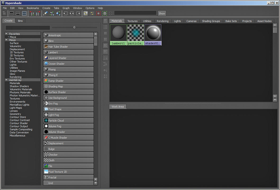
FIGURE 7.1 The Hypershade window in all its glory. The Create panel is on the left, displaying material nodes and many other nodes. The Bin is on the top right, and shows you the nodes you have created in your scene, arranged alphabetically by default. The Work Area is where you will connect nodes and build your shading networks.
Note: The Dependable Defaults
Notice that lambert1, particleCloud1, and shaderGlow1 are created by default in your scene. Lambert1 is applied to all geometry by default, just so that Maya can display the geometry in panel. ParticleCloud1 is a default particle shader, created for the same reason, and shaderGlow1 controls the glow on shaders. You can only have one shaderGlow node in your scene, so if you need more than one object to glow, you will have to use render layers.
The Main Menu
At the top of the Hypershade sits the main menu. This menu, shown in Figure 7.2, is not utilized too often because the most frequently used functions of the Hypershade are arranged in the form of buttons just below the main menu.
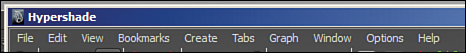
FIGURE 7.2 The main menu of the Hypershade is a necessary part of the UI, but you won’t be using it very much when creating networks.
The two items here you will use most frequently are the File and Edit menus. You can import and export shaders and shading networks from the File menu, and you can perform some useful tasks such as deleting unused nodes and duplicating shading networks from the Edit menu. Bookmarks are useful as well; you can create a bookmark that will save any view you are looking at in the Work Area. This is helpful if you are working on a complex network and need to work on something else for a while. The Create, Tabs, Graph, Window, and Options menus contain options and commands that are more easily accessed through other panels and buttons or are very infrequently needed. Therefore, we don’t even need to go through them to fully understand the Hypershade.
The Menu Bar
This collection of frequently used tools and commands will serve you very well when using the Hypershade, as seen in Figure 7.3.
You will find that most of the tools you need from the Hypershade menu are found in the menu bar. Let’s take a look across, from left to right, and see what each one does. Here are the icons and a brief explanation of their uses:
The first four buttons control how the Hypershade looks. You can hide the Create Panel, the Bins, or the Work Area.
These buttons show the previous graph and the next graph. Think of these almost as an undo and redo queue for views of your graphs—useful for when you have loaded many materials and are making changes to a few attributes on different materials in succession.
The next three buttons—Clear, Rearrange Graph, and Graph Selected—give you the main tools for sorting your Hypershade’s Work Area. Clear does just that. Rearrange will arrange the nodes nicely in your Work Area to give you a clean layout. Graph Selected graphs all shaders in the Work Area that are connected to the selected object or objects. A very common workflow is to select the object whose shader you want to examine and just click this last button rather than finding a shader in the Bin and graphing it.
These buttons—Input, Input and Output, and Output—determine whether the Work Area displays the nodes that affect the selected node, are affected by the selected node, or both.
These buttons are the controls for working with assets. We’ll come back to these tools in Hour 23, “Correct Project Management and Scene Workflow.”
Finally, this area is used to search the Hypershade. It is very powerful and can use wildcards (*). Remember, though, that Maya is always case sensitive. For example, searching for Blinn will not show the node blinn1. The left icon with the arrows will highlight if a filter is in place; clicking it clears the filter.
The Create Panel
On the left you will see the Create panel. We briefly discussed this panel last Hour, but now we’ll take an even closer look. At the top of this panel are two tabs: Create and Bins. The Bins panel is the area to the top right of the Hypershade, where your shading networks are displayed. The Create panel is used to create the nodes you will assemble together into complex shading hierarchies. To create any node listed in this menu, simply LMB click on it. The node will be created in the Work Area, and if it is a top-level material node such as Blinn or Lambert, it will appear in the Materials bin. Figure 7.4 shows blinn1 that just appeared after clicking the Blinn button in the Create panel.

FIGURE 7.4 Clicking on the Blinn button in the Create panel creates the node and loads it into the Materials bin and the Work Area.
The left side of the Create panel shows you the different categories of nodes you can create. Clicking any one or multiple filters will load them into the right side of the Create panel.
Note: All Displayed
Because Maya is so powerful, there’s an almost overwhelming number of different nodes you can create, all of which are displayed by default. Get used to the filters by clicking on them and trying them out a bit.
The Work Area
The Work Area is where we will create all of the shading networks, as well as some interesting other relationships. The window responds to all of the normal orthographic view camera controls (Alt+MMB for moving, Alt+RMB for zooming). Click on Blinn to create a new material node called blinn1. Double-clicking on any node will load that node in the Attribute Editor. Once the Attribute Editor is open, clicking on any node will load it into the Attribute Editor as well.
Right-Clicking
Most of the frequently used functionality of the Work Area is accessed by right-clicking on a node. Figure 7.5 shows the marking menu that appears.
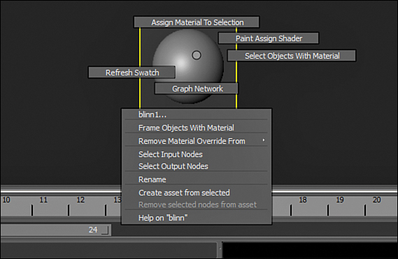
The common workflow is to create a node and then start right-clicking and applying attributes and connections to it. You then create more nodes, and connect more attributes. In this way, you create a web of interconnected nodes, otherwise known as a shading network. Let’s take a look at what that might look like.
Connecting Nodes
In the Create panel, click on the Checker button. It is in the list of nodes; you may have to scroll down to find it. Once you do, you will see the node has been created and loads into the Work Area. Remember, it won’t show in the Bin because this is not a top-level material like blinn1 is. Select the checker1 node and MMB drag it onto blinn1. In Figure 7.6, you see the marking menu that appears.
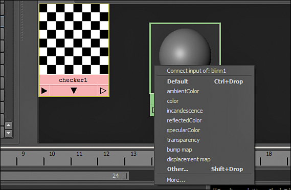
FIGURE 7.6 This marking menu gives you a lot of the common attributes; you can connect checker1 to blinn1.
The action of MMB dragging one node to another selects the default output of a node (in this case, the color) and gives you a selection of inputs to connect it to. The default input on blinn1 is also “color.” So if you choose default, the checker texture will be assigned as the color channel of the blinn1 material. Alternatively, you can choose any of the attributes shown to connect the checker to, or you can choose Other to bring up the Connection Editor.
Tip: Connecting Nodes Anywhere You Can
Maya does not care where you connect nodes, be it using the Hypershade, the Connection Editor, a script, or expressions. When you don’t choose a default connection, Maya brings up the Connection Editor and gives you the option of connecting any output and input available on the selected objects. You should just note that the actual connecting of attributes is the same no matter what method you use, and that the Hypershade is just another way of connecting nodes that is material centric and very visual.
Also, you can choose which output you want to connect on the checker node by right-clicking on the node’s output (arrow icon on the bottom right) and then choosing whichever output you want. A menu with a list of choices will appear like in Figure 7.7.
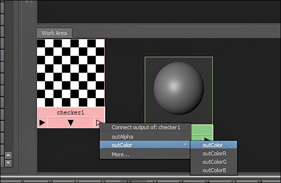
FIGURE 7.7 The other way to connect attributes; choose any output you like to connect to the input of blinn1.
Now that you know how to connect attributes, we will create a shading network in the next section. We are going to do some more complex arrangement of nodes that produces a simple result. We can attach almost any attribute to another attribute, provided that it produces the right type of data. For instance, we can connect the outColor attribute of checker1 to the Color attribute of blinn1, because it is looking for an RGB input. However, because the Reflectivity attribute is a single attribute that goes from 0 to 1, you could not connect the outColor to the reflectivity. You could, however, connect the outColorR (red) because this is a single channel. You could also connect the outAlpha; again, one channel. This will make more sense as we start creating multiple connections.
Creating a Simple Network
Let’s create a simple network for a cartoon eye material. It will need the iris and pupil color, it will need reflectivity and specular, and we’ll even create a faux highlight so that the eye always looks like it’s catching some of the light in the scene:
![]() We’ll start with a Blinn. Create a Blinn material and move it (LMB click and drag) to the side of the Work Area to make room for the next couple of nodes we will create.
We’ll start with a Blinn. Create a Blinn material and move it (LMB click and drag) to the side of the Work Area to make room for the next couple of nodes we will create.
![]() Create a ramp texture (scroll down the Create menu; it’s there).
Create a ramp texture (scroll down the Create menu; it’s there).
![]() MMB drag the ramp texture onto the blinn1 material and then choose color, as shown in Figure 7.8.
MMB drag the ramp texture onto the blinn1 material and then choose color, as shown in Figure 7.8.
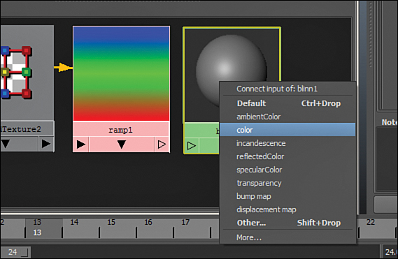
Now we have a connection. In the Attribute Editor, with the ramp1 node selected, you can see the many options for this texture:
![]() First, make sure the ramp’s Type is set to “V Ramp” so that the color will be aligned correctly on the eyeball.
First, make sure the ramp’s Type is set to “V Ramp” so that the color will be aligned correctly on the eyeball.
![]() Then click anywhere in the ramp’s color area to add a color handle. You can move the created handles around by adjusting the round handle on the left, and remove a color handle by clicking on the box on the right. Add five or six color handles and make yours look like mine in Figure 7.9.
Then click anywhere in the ramp’s color area to add a color handle. You can move the created handles around by adjusting the round handle on the left, and remove a color handle by clicking on the box on the right. Add five or six color handles and make yours look like mine in Figure 7.9.
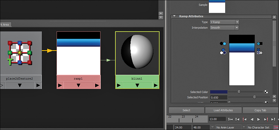
![]() To change the color, select a handle by clicking on the round icon and then click on the swatch that sits below the ramp’s color. In Figure 7.9, the dots are arranged to have a nice gradient in the iris color.
To change the color, select a handle by clicking on the round icon and then click on the swatch that sits below the ramp’s color. In Figure 7.9, the dots are arranged to have a nice gradient in the iris color.
Now we’ll add a little brightness to the edges of the material. Create another ramp shader and a samplerInfo node, as shown in Figure 7.10.

Now we will connect these two nodes in a unique way:
![]() MMB drag the samplerInfo node onto the ramp node.
MMB drag the samplerInfo node onto the ramp node.
![]() Choose Other.... The Connection Editor will open.
Choose Other.... The Connection Editor will open.
![]() Click on the samplerInfo node’s facingRatio attribute in the left column of the Connection Editor. Then expand the uvCoord attribute and click on the vCoord attribute on the ramp node (right side of the panel).
Click on the samplerInfo node’s facingRatio attribute in the left column of the Connection Editor. Then expand the uvCoord attribute and click on the vCoord attribute on the ramp node (right side of the panel).
You have just made it so that the amount a polygon faces the camera determines what position in the ramp Maya is going to use to display on that face. Figure 7.11 is a shot of the Connection Editor, and as you can see, connecting nodes is as simple as selecting them.
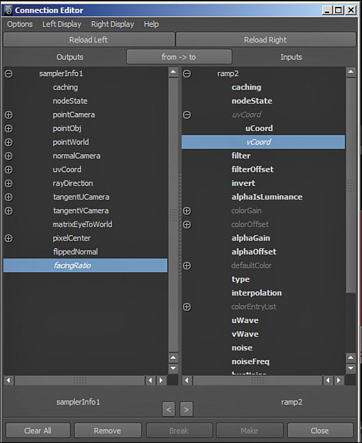
FIGURE 7.11 The samplerInfo node correctly connected to the ramp node. This creates an interesting effect we will tweak in a minute.
Keep in mind that Maya can connect attributes that read and write the same type of data. A samplerInfo returns a value between 0 and 1, depending on how much a face is turned toward the camera. It just so happens that the position of a color handle on a ramp can be any value between 0 and 1.
Now we will adjust the ramp’s colors to make it so that the more “away facing” a polygon is, the brighter it is rendered. This gives a faux light-absorption effect:
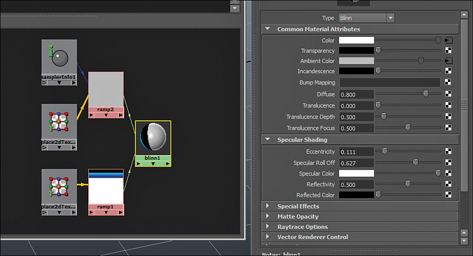
![]() Adjust your ramp to look like mine in Figure 7.12 and then MMB drag the ramp onto the Blinn.
Adjust your ramp to look like mine in Figure 7.12 and then MMB drag the ramp onto the Blinn.

FIGURE 7.12 The shading network is starting to form. It is not uncommon to have a material with dozens of nodes interconnecting to create complex effects.
![]() Choose the ambientColor attribute when the marking menu pops up.
Choose the ambientColor attribute when the marking menu pops up.
![]() RMB click and drag on the blinn1 node in the Work Area and choose Graph Network so that we can make sure your node network looks like mine in Figure 7.13.
RMB click and drag on the blinn1 node in the Work Area and choose Graph Network so that we can make sure your node network looks like mine in Figure 7.13.
Note: Graphing Networks and Clearing the Work Area
Be careful when using the Graph Selected button or the Rearrange Selected button in the Hypershade. The danger is that you will clear the Work Area unintentionally because either all your nodes are not selected or a new node you have created is not connected to a shading network yet.
There is just one more step to do: Add the faux highlight that we see in so many cartoon characters’ eyes. This is a faked effect; the real highlight we see on a character’s eye is the reflection of a light source. So although this method is not recommended for realistic materials, it gives us a good chance to look at the nodes a little closer and to give our eye a nice added effect:
![]() Create a new ramp by clicking the Ramp button in the Create panel of the Hypershade. It will load into the Work Area automatically.
Create a new ramp by clicking the Ramp button in the Create panel of the Hypershade. It will load into the Work Area automatically.
![]() RMB drag the ramp onto blinn1 and choose “incandescence,” as shown in Figure 7.14.
RMB drag the ramp onto blinn1 and choose “incandescence,” as shown in Figure 7.14.
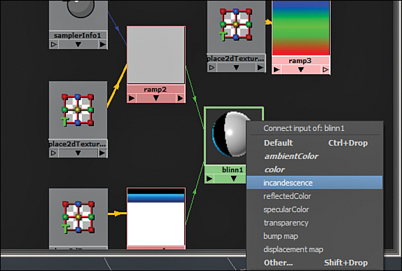
FIGURE 7.14 The incandescence attribute controls how much light appears to be coming out of a material.
We will now adjust the placement of the ramp and turn it into the correct shape so that it appears to be a highlight:
![]() Create a polygonal sphere by clicking Create, Polygon Primitives, Sphere or by clicking the sphere icon in the Polygons shelf. Any size will do.
Create a polygonal sphere by clicking Create, Polygon Primitives, Sphere or by clicking the sphere icon in the Polygons shelf. Any size will do.
![]() In the Hypershade, and with the sphere still selected, RMB click and drag upward to choose Assign Material to Selection.
In the Hypershade, and with the sphere still selected, RMB click and drag upward to choose Assign Material to Selection.
![]() Press the 6 key to make sure your panel is displaying textures.
Press the 6 key to make sure your panel is displaying textures.
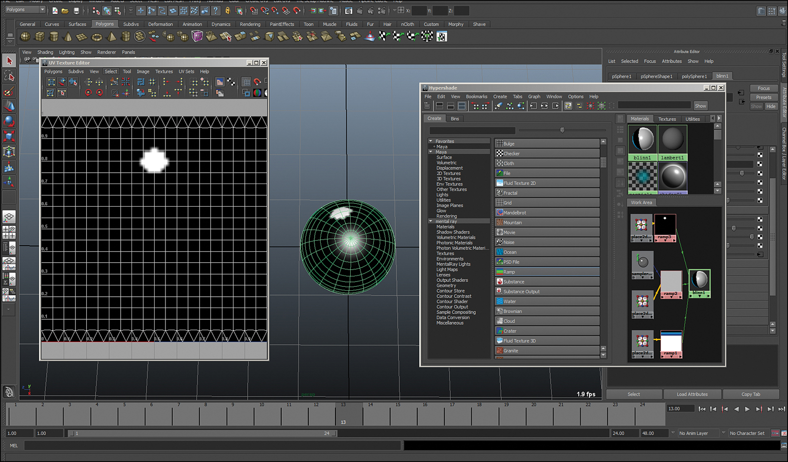
![]() Lastly, open up the UV Texture Editor by clicking on Window, UV Texture Editor. Your workspace should look something similar to mine, as shown in Figure 7.15.
Lastly, open up the UV Texture Editor by clicking on Window, UV Texture Editor. Your workspace should look something similar to mine, as shown in Figure 7.15.

FIGURE 7.15 We will use this workspace layout to accomplish the final task of adding the highlight to the eye.
![]() Click on the newly created ramp3 and go into the Attribute Editor.
Click on the newly created ramp3 and go into the Attribute Editor.
![]() Change the ramp type to Circular, change the interpolation to None in the drop-down box, and change the colors in the ramp to look like mine in Figure 7.16.
Change the ramp type to Circular, change the interpolation to None in the drop-down box, and change the colors in the ramp to look like mine in Figure 7.16.

![]() In the UV Texture Editor, go to Image and choose ramp3. It will load the ramp as the display image in the UV Texture Editor but also in the panel.
In the UV Texture Editor, go to Image and choose ramp3. It will load the ramp as the display image in the UV Texture Editor but also in the panel.
![]() Now in the Hypershade, choose the place2DTexture node that is connected to ramp3 and go into the Attribute Editor. Change the Y offset (second box next to the Offset attribute) to –0.3. You can also adjust the size of your highlight by moving the black color in the ramp3 node up or down in the ramp. If all goes well, your panel should look like mine in Figure 7.17.
Now in the Hypershade, choose the place2DTexture node that is connected to ramp3 and go into the Attribute Editor. Change the Y offset (second box next to the Offset attribute) to –0.3. You can also adjust the size of your highlight by moving the black color in the ramp3 node up or down in the ramp. If all goes well, your panel should look like mine in Figure 7.17.
Let’s take a look at how this looks in render:
![]() Click in your panel and press F to frame the sphere.
Click in your panel and press F to frame the sphere.
![]() Then press F6 to bring up the rendering menu set and click Render, Render Current Frame.
Then press F6 to bring up the rendering menu set and click Render, Render Current Frame.
As you see in Figure 7.18, the sphere renders with our eye texture nicely, complete with the rim light that comes from the samplerInfo node and the faux highlight we just made with the circular ramp.

Included in this Hour’s Bonus folder are a few Maya materials for you to import and apply to your objects. Graph the materials in your Hypershade and observe the connections that are being made to give you ideas on creating your own complex networks. You can open the .ma files to view the materials, or you can load them into your scenes by clicking in the Hypershade on File, Import and then choosing the material you would like to use.
Summary
The Hypershade offers Maya’s most visual way to connect nodes together. Because creating materials involves creating multiple connections, naturally the Hypershade is organized into multiple panes to help you keep the nodes organized. You saw how creating nodes moves them automatically into the Work Area so you can begin connecting them together. Graphing a network organizes the Work Area neatly. You saw how a ramp texture is versatile and can be used to create a variety of effects. We used the UV Texture Editor, Hypershade, and Attribute Editor in unison to get the results we desired out of the highlight effect added to the eye material.
Q&A
Q. I created a node and then graphed the network, which cleared the Work Area, but now I can’t see my node anymore. What happened?
A. The Graph Network command only arranges nodes that are connected in a network. The node you created still exists, but it might be in one of the other bins in the Hypershade. Look through the bins by clicking on the top tabs and see if you can find the node you are looking for. MMB drag it back into the Work Area to start connecting it to other nodes again.
Q. Why is my texture black in the panel?
A. To view textures in a panel, you press the 6 key. However, if the 7 key is pressed (lighting preview) and there are no lights, everything will be black. Press 5 to return the panel to smooth shading with no lights, then press 6 again and it should be fine.
Q. What are all these place2DTexture nodes that are generating automatically when I create any texture?
A. These nodes control the placement, orientation, scale, offset, and so on, of a 2D texture. As you can see in the UV Texture Editor in Figure 7.17, the offset value we put on the ramp3 node moved the circle from the center of the texture up toward the top. These are essential nodes that help you further define the placement of your textures on your objects.
Q. How do I save a material so I can put it in another scene? Shouldn’t I be saving all of my materials in some sort of “library”?
A. That’s a great idea. You can select a material in the Hypershade and click on File, Export Selected Network. Save them either to the Shaders folder in your project or to a new folder you create for the purpose of being your library. Note that there is no Material folder created in the default Maya project folder; this is one of the instances where terms are slightly confused.
Workshop
The workshop contains quiz questions and exercises to help you solidify your understanding of the material covered. Try to answer all questions before looking at the “Answers” section that follows.
Quiz
1. What is the difference between a material and a texture?
2. When you create a new node in the Hypershade, what panel does it show in immediately?
3. What are some of the different methods you can use to connect nodes?
4. When you want to see all of the connected nodes in a network, what do you do?
5. How do you only display a certain type of node in the Create panel?
Exercise
Create a small shader library using the skills you learned for connecting nodes in the Hypershade. You could make a themed library. For example, a city-themed library should contain some bricks, metals, old woods, and so on. We only have a few pages to explore the use of the Hypershade in this book, which is not enough to cover every single material and texture node. Therefore, you should create each material node one at a time and look at its attributes in the Attribute Editor. I also highly recommend you take a look at the Help for a node by clicking the Help menu at the top of the Attribute Editor. Choose the Help specifically for the node you are looking at. In other words, if you are looking at a lambert, choose “Help on Lambert.” After you create a few simple networks, be a little more adventurous and start creating some more complex effects. Start applying image textures as values in a ramp, for example, or use a checker texture as both a color and a reflected color attribute to get an interesting mirror effect.
Answers
1. A material is a top-level node that connects a shader with associated textures and other render nodes. A texture is any image or node that is used in a material’s attributes, such as color, transparency, and so on.
2. All newly created nodes appear in the Work Area immediately.
3. Middle mouse dragging one node on top of another in the Work Area allows you to connect the default output to a list of inputs. RMB clicking and dragging on the output (black arrow on the bottom right) of a node allows you to choose the output you would like to connect, and then LMB clicking on another node allows you to choose the input. You can also MMB drag a node right out of the Hypershade and drop it on any attribute in the Attribute Editor.
4. RMB click and drag down to choose Graph Network.
5. You can filter what types of nodes display in the Create panel by selecting the node type in the left of the panel. This filters the display in the right of the Create panel. You can also Shift-select multiple types or use the group filters (Favorites, Maya, and so on). To add a material to your favorites, just RMB click on the node in the Create panel and choose Add to Favorites.