
BIM
Abstract
This chapter introduces the concept of Building Information Modeling applications and their use in practice. It starts by presenting the history of BIM through to the modern way of work and describes the tools and processes used by architects and engineers of different design team disciplines. A breakdown of the UK government BIM direction and aims is also included. It then explains the processes and industry transfer standards involved with a modern way of working and the available information content. The chapter also includes the BIM process for three projects: The National Museum of Qatar; Leeds Arena in the UK; and the Alta Bates Summit Medical Centre in the US.
Keywords
Building Information Modeling; UK government BIM aims; BIM in practice; savings with BIM; Tekla Structures; Tekla BIMsight; industry transfer standards; nD information; reference models
Chapter Outline
How BIM Is Applied in Practice
Linking Systems through Open .NET Interfaces
Sample BIM Project – Alta Bates Summit Medical Centre - by DPR Construction Inc.
Sample BIM Project – The National Museum of Qatar (Arup)
Interoperability and Principle Industry Transfer Standards
Introduction
Technology to access and control construction information is constantly changing and the relevant information is required to be available on various devices and platforms. For example even preparing this chapter has involved storing information on the ‘Cloud’, interfaced from a smartphone, various laptops, and a PC, all on different platforms and this is just for controlling text. The construction industry is moving to digital integrated design team project delivery, with all of the necessary information being available at any stage of the contract and beyond. Each project design team can be formed from many different players depending on the actual work requirements and content. For example, a design team could include the client; architect; engineer; MEP (mechanical, electrical, and piping); contractors; etc. One of the processes that support these developments is Building Information Modelling (BIM). BIM is not a single 3D application; it is a process that streamlines the product model content and delivery.
It is worth concentrating on the ‘Information’ part of BIM before addressing the BIM process. Information always needs to be collected and contained in a physical object or system. In history this could have been on a stone tablet, or nowadays a book or ‘project library’ would be made available to the reader or viewer. This really is the same with BIM, however, the whole project information is not just available as a great volume, but broken down to object-level nuggets of information for ease of reference.
A product model can be built or defined with a 3D or 4D application, where the latter is the 3D information which also encapsulates the time information. This can also include manufacturing information, start and completion dates, maintenance information, and even the required special demolition procedures, as the model can support the full life cycle of the building or project. However, the BIM model is not limited to just 4D information, as costing can be included, which is sometimes referred to as 5D information, or really anything that the user wants to track (nD information) and control.
Sometimes BIM is thought to be just another service that provides users with instant online access to an ever-increasing stream of constantly evolving, instantly updating digital data. However, if the processes are in place then real project control is possible. Many times it is said that: ‘Nowadays to change a pump physically on a building site is relatively simple. However, changing all of the 3D models, drawings, sketches, specifications etc. is the hard and time-consuming part’. Adopting the BIM process will revolutionise this, as the information has only to be changed once, with the authoring application, after which the rest of the design team members can simply reinsert the new ‘reference model’, with all the latest information, ensuring all the models are up-to-date.
History of BIM
2D drawing systems have been used since the early 1990s and were really used only as ‘electronic drawing boards’, copying and pasting details or ‘blocks’ to reproduce drawings quicker than the older manual processes. However, as far as interoperability was concerned there were no advantages. Various applications allowed different drawings or blocks to be imported into the working drawing using some form of ‘X-Ref’ options, which really was the start of the reference model concept.
General Computer-Aided Design (CAD) tools were used for a while, leading to bespoke solutions which were developed to suit each industry or design team member’s requirement. For example, tools used by architects would require different functionality from the toolkit required by engineers. Also a structural engineering application would have different drawing requirements from a Mechanical Electrical and Piping (MEP) solution. It is interesting to note that in many companies the technicians will produce the drawings, with engineers just resolving typical project sections or sketches.
In the building and construction sector, ‘Information Modelling’, is normally defined as the computer representation of a building or structure, including all the relevant information required for the manufacture and construction of the modelled elements. The elements or objects are required to be intelligent and should therefore know what they are; how they should behave in different circumstances; and their own properties and valid relationships. A simple example of this would be the reinforcement in a pad foundation. If the foundation size is modified then the embedded reinforcement should update and reposition itself accordingly. This is very different from a computer-generated model, which has been constructed for purely visualization purposes, where every objected is a non-related element.
The structural steelwork industry is always recognised as the lead sector in 3D modelling solutions and their developments can be traced back over the last 20 years with applications such as the forerunner of Tekla Structures. This type of application allowed the 3D steel frame to be modelled and the connection applied by the use of user-defined macros, which allowed the automatic production of general arrangement drawings, fabrication details, and then, after a few more years, the development of links to CNC (computer numerically controlled) machines, for the cutting and drilling of steel sections and fittings.
Once the 3D modelling technology was extended to include Parametric Modelling (true solid objects) then clash detections systems were able to be developed. Hard or soft clash detection allows applications to identify any possible material overlapping conditions or objects existing in the same space.
Nowadays Globally Unique IDs or Globally Unique Identifiers (GUIDs) are available in most applications, which are unique strings usually stored as a 128 bit integer, which is associated with the objects. The GUID is used to track the objects between applications for change management. Some systems allow the support for internal and external GUIDs. The term GUID usually, but not always, refers to Microsoft’s Universally Unique Identifier (UUID) standard.
From the start of BIM, only drawings and reports were made available, as the actual BIM model was always confined to the office where the more powerful computers were situated. However, as computers have advanced, the models are now accessible on laptops and, over the last few years, even on tablets.
What Is BIM?
So what is BIM? It could simply be defined as rapidly evolving collaboration tools that facilitate integrated design and construction management. The importance of ‘I’ in BIM should never be underestimated, as this becomes a project or support for the company’s enterprise framework and not just a means for ‘building models’. This information means that more work is done earlier in the project to support green issue concepts, as less waste saves both materials and energy.
BIM enables multidimensional models including space constraints, time, costs, materials, design and manufacturing information, finishes, etc., to be created and even allows the support for information-based real-time collaboration. This information can be used to drive other recent technologies including city-sized models, augmented reality equipment used on site, radio-frequency identification (RFID) tags to track components from manufacture to site, and even the use of 3D printers.
It may be useful to consider the players who would want to have access to the BIM models. Not limiting the list they could include the clients, local authorities, architects, engineers (structural, civil, and MEP), main contractors, steelwork and concrete subcontractors, formwork contractors, and all site personnel. Until recent years BIM was only available as a solution for architects, engineers, and steelwork contractors, leaving everyone else just to work with 2D drawings that may be industry-specific but not totally readable without knowledge of that environment.
Various references have been made to the architects’ BIM model or the structural BIM. However, they really are the same, as the boundaries between their models and their content are lessening all of the time. Architects’ BIM models will include structural member sizes, but the models that they produce do not normally need to include the material grades, reactions, and finishes. Where the model is produced by the steelwork contractor, it will include at least the manufacturing details and all the information necessary to order, fabricate, deliver, and erect the members. The MEP contractor could also define the site fixings on his versions of the model, as the contractor will want to know when the member will be on site, where it will be fixed or poured, and how much the item costs. The client’s view of the same member would be for control and for possible site maintenance. For this reason various models are created in the ‘best-of-breed’ authoring applications and shared with other design-team members as reference models, which are normally in the form of Industry Foundation Class (IFC) files for all structures except the plant and offshore markets, where CIMsteel Integration Standards (cis/2) and dgn format files are the dominant interoperability formats.
It is so much easier to work with a BIM model and to explore the building in 3D with rich information, than looking at hundreds of drawings and having to understand the industry drawing conversions. Now users can simply click on an object and obtain all the information that they require either through the native object, if in the authoring application, or through the reference model or even from a viewer or collaboration tool.
UK Government Recommendations
The UK and other governments have expressed support for BIM over recent years. However, in March 2011 the UK government published a BIM Strategy Paper. In fact the UK government has made it clear that BIM needs to be adopted on all of their projects within the lifetime of the present parliament to save the model objects from being rebuilt many times within the same project by different design team members.
The aims and objectives of the working group were:
• Identify how measured benefits could be brought to the construction industry through the increased use of BIM methodologies
• Identify what the UK government as a client needs to do to encourage the widespread adoption of BIM
• Review the international adoption of BIM including the U.S. federal government
• Look into government BIM policy to assist the UK consultant and contractor base to maintain and develop their standing in the international markets
The general recommendations were:
• Leave complexity and competition in the supply chain
• Be very specific with supply-chain partners
• Measure and make active use of outputs
• Provide appropriate support infrastructure
• Have a clear target for the ‘trailing edge’ of the industry
The report also defines the project BIM maturity levels, from Level 0 to Level 3. As a quick summary Level 0 is where just CAD tools have been adopted; Level 1 is where 2D and 3D information is used to defined standards; Level 2 is where BIM applications are used with fully integrated model collaboration; and Level 3 is where BIM models are used for project/building lifecycle management. See Urn 11/948, which is a report commissioned by the Department of Business, Innovations and Skills, first published in July 2011, for further information.
What the UK government wants is:
How BIM Is Applied in Practice
If a BIM model is being enhanced on the authoring application, it is normally referred to as a physical or native model, which can be enhanced using normal authoring tools. If the model is to be fixed by one design team member, then an IFC file or other reference models are normally adopted where objects can be commented upon but not changed by other members of the design team.
Tekla Structures
Tekla Structures is a multi-material BIM software tool that streamlines the construction design and delivery process from the planning stage through to design and manufacturing, providing a collaborative solution for the cast-in-place (in-situ)/precast concrete, steelwork, engineering, and construction segments.
The structural BIM is the part of the BIM process where the majority of multi-material structural information is created and refined. These are normally created by the structural engineer as architects work with space, mass, texture, and shapes and do not work with building objects in the same way as defined in the structural BIM. However, the connection between the architects’ models and structural BIM is a very obvious way to help in the future development of intelligent integration, which should be always available in the form of reference models in the same way that the XREF function is used in a 2D drawing. These reference models could also be 2D information for collaboration with non-BIM applications.
The model starts to evolve during the engineering stage, where conceptual decisions of the structural forms are made. It is sometimes thought that the design portion of Analysis & Design (A&D) is just the pure physical sizing of the structural elements. It is in fact more than that, as it should also include the engineering and the ‘value engineering’ of the project, including all materials, their relationships, and their reference to the architectural and service objects, together with possible links to other design systems using .NET technology to form an Application Programming Interface, or API as it is more commonly known.
In its basic form, .NET is a flexible programming platform for connecting information, people, systems, and devices together using a modern programming environment and tools based upon the Microsoft® Visual Studio.NET developments. There are over 30 programming languages that are .NET enabled which allow true object information to be seamlessly transferred between systems. So for example element information and geometry can be passed from modelling applications to any other .NET-enabled system. These could be A&D systems, management information systems, cost control, or just systems used for internal bespoke company development.
One of the principal advantages of the structural BIM is that the project is built for the first time in the memory of the computer, before any physical materials are involved. This allows the scheme to be refined to a greater extent, allowing full clash checking facilities, automatic drawing, bar bending schedules, and report preparation. Modern applications also allow the drawings and reports to be automatically updated should the model be amended, thus allowing change management to be controlled and different design solution scenarios to be considered at any time together with having links back to the A&D systems if required.
For further information on the Tekla Corporation or Tekla Structures visit www.tekla.com. For Web tutorials on Tekla Structures or for general BIM lessons information see www.tekla.com/international/solutions/building-construction/videos/FirstSteps/index.html.
Linking Systems through Open .NET Interfaces
Sometimes using industry standard files is not appropriate when tight linking of applications is required. For example, a user may want to share design information between a modelling system and say A&D applications, management information systems (MIS), enterprise solutions, connection and fire design systems, project management systems, or planning systems.
In such a case the objects, a simplified form of the object, or just the object attributes, can be passed between systems using the Open .Net interface as defined above. This same interface could also be used for model transfer or for repetitive processes such as drawing and report creation.
Tekla BIMsight
Tekla BIMsight has been written by the Tekla Corporation, which is a Trimble company, and is a free BIM collaboration tool which is available for anyone to download and install. It is also an easy-to-access application that presents the complete project including all necessary building information from different construction disciplines. It is also much more than a viewer as one can communicate using the model with anyone, not just Tekla Structures or other BIM software users.
With Tekla BIMsight one can:
• Combine multiple models and file formats from a variety of BIM applications into one project
• Share building information for coordination between different trades and deliverables
• Identify and communicate problem areas, check clashes, manage changes, approve comments, and assign work in 3D by storing a history of different view locations and descriptions in the model
• Measure distances directly in the model to verify design requirements and construction tolerances
• Control the visualization and transparency of different types of parts in the model to make it easier to understand complex and congested areas of the project
• Query properties such as profile, material grade, length, and weight from parts
• Tekla BIMsight can be downloaded from www.TeklaBIMsight.com, which also includes video tutorials and a user forum
For interoperability the file formats supported by Tekla BIMsight currently are IFC (IFC, IFC XML, and IFC ZIP), dwg, dgn, and xml.
Savings with BIM
It is always hard to establish Return on Investment (ROI) and project savings with regards to any software systems. However, as the BIM project is created within the memory of the computer before any materials and site personnel’s time are involved change is cheap. Various report and white papers regarding the cost of change and constant remodelling was one of the reasons for the UK government’s BIM initiative.
Sample BIM Project – Alta Bates Summit Medical Centre - by DPR Construction Inc.
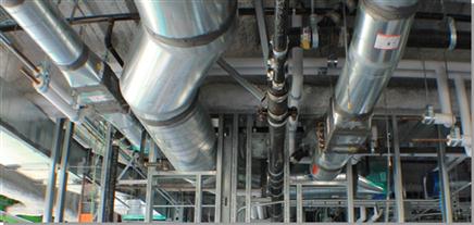
The addition to the Alta Bates Summit Medical Campus (ABSMC) is a $289 million, 13-storey patient care pavilion and future home of over 200 licensed beds and the facility is due to open in January 2014. DPR’s highly collaborative Integrated Project Delivery (IPD) team was faced with many challenges. The use of Tekla Structures and Tekla BIMsight has grown significantly since the start of construction in 2010. Modelling scopes within Tekla Structures includes Structural Steel, Cast-in-Place (CIP) Concrete, Reinforcing Bar, Miscellaneous Steel and Light Gauge Drywall Framing. See Figures 52.1 to 52.7.


Seismic design requirements set forth by the Office of Statewide Healthcare Planning and Development (OSHPD) in addition to a hybrid steel and concrete shear wall structure required in-depth coordination between rebar and steel fabrication models. This coordination effort between multiple trade partners would not have been achieved without the use of this highly collaborative and detailed BIM platform. Since subcontractors Herrick Steel and Harris Salinas Rebar were both detailing with Tekla, it was very useful to provide the rebar detailer with the steel model during detailing to identify constructability issues with anchor bolts, stiffener plates, and other connection details that were not shown in the engineering design model.
More recently, the ABSMC Project has implemented the concept of Dynamic Detailing within Tekla Structures on both the reinforcing steel and drywall framing. By referencing in the structural steel Tekla model along with IFC models of the MEP&FP systems, Harris Salinas rebar and DPR Self-Perform Drywall were able to identify conflicts during the process of modelling, as opposed to the traditional method of modelling in a silo and having to rework the modelling after clash detection. This workflow results in a more efficient, streamlined workflow with fewer chances for modelling errors (see Figures 52.1 and 52.2).
The DPR Self-Perform Drywall detailer, Robert Cook, has developed an efficient workflow to detail the rebar using multiple custom components. Robert Cook is also creating drywall framing assembly spool sheets that can be printed to 11” × 17” or viewed on an iPad to help the site team to increase efficiency and quality while reducing rework. As all the ductwork is fabricated and assembled directly from the model, DPR drywall is now able to install framing around the duct and pipe openings prior to MEP installation and be confident that the framing is in the right location to align with the prefabricated ductwork and piping.
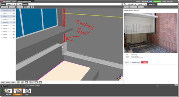
In addition to Tekla Structures, Tekla BIMsight has been used to convey differences between site conditions (see Figure 52.3), and the design model related to the exterior skin and expansion joint design. The Alta Bates project requires seismic expansion joints where surrounded on three sides by the existing hospital campus and around a five-storey pedestrian bridge. The comment tool, dimensioning tool, and photo attachments were used to convey coordination and constructability issues to the designer, fabricator, and installer.
Sample BIM Project – The National Museum of Qatar (Arup)
The National Museum of Qatar in Doha (see Figure 52.8) is the flagship project for an important series of cultural and educational projects which have being commissioned by the Qatari government. The project, which drew inspiration from the desert rose, has now started on site and has been in the planning phase since 2008. The desert rose is a crystalline formation found below-ground in saline regions of the desert. When imagined as a building, the result is a four-storey, 300 metre by 200 metre sculpture of intersecting discs that are up to 80 metres in diameter.
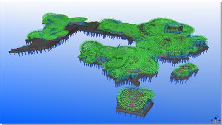
The evolved structural solution consists of radially and orthogonally framed steel trusses, supporting fibre-reinforced concrete cladding panels to create the required aesthetic and performance characteristics of the building envelope.
Challenges
The key challenge for the design was the highly complex geometry of the disc interactions. No two discs are the same and no two discs intersect each other in precisely the same way (see Figure 52.9). The galleries and other key spaces in the building are created by the interstices between the discs; any alteration to the architecture involves moving discs and thereby moving the structure within the discs. This has led to an evolution of systems and processes which were required to handle, manipulate, and develop geometric ideas from the architects, so that engineering solutions could be established before communicating these in their most useful form to the wider project community.

For this reason, the structural modelling (analysis, design, and manufacturing and construction) needed to address the following requirements:
• Position elements in the correct place in the 3D space within the cladding envelope
• Generate and model elements as efficiently and automatically as possible in order to keep up with iterations of the architectural arrangement
• Facilitate cross-discipline coordination, both with the Arup MEP design and 3D modelling teams in London, plus the architectural team based in Geneva and Paris together with the client in Qatar
Leeds Arena, UK. Fisher Engineering Limited
Leeds Arena is the United Kingdom’s first purpose-built fan-shaped arena (see Figures 52.10 to 52.15). Using this form of geometry allows every spectator to have a perfect view of the centre stage. The main facades are rounded and have a domed effect, which terminates with a flat roof. Formed with two columns, one sloping outwards and the second spliced to the top and cranked inwards, these curving elevations are clad with a honeycomb design of glazed panels that contain lights of changing colours.


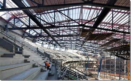
The steel-framed structure of the roof is supported by a series of 13 trusses spanning up to 70 meters across the auditorium with the five central trusses being supported over the stage area by a 170-tonne trussed girder and plated columns, which form the 54m long × 10.5m deep proscenium arch. The proscenium arch truss was delivered to site in 32 separate sections; a total of nine trailer loads. Assembling the truss took three weeks, using two large mobile cranes.
The bowl terraced seating is formed from precast concrete units supported on a radial steelwork structure, braced and tied into two main concrete stair cores that provide the required stability (see Figure 52.14). Acoustic resistance is a major design factor for a venue of this size, which is situated within a city centre, and required the structure to be shrouded in a skin of precast concrete wall panels and topped with a concrete roof topping on a metal deck.
A BIM strategy was essential for efficiency
With so many subcontractors providing major structural elements, all of which required prefabricated connections to interface with the complex geometry, it was clear from the start of the project that a BIM strategy was essential to obtain the necessary project efficiencies through the evolving design and collaboration process. The BIM model proved invaluable to all parties involved as it was passed between the design team and contractors for clash detection and for the resolution of incomplete design issues. This greatly assisted the project programming, sequencing, and general constructability.
Technical Detail
For readers who are interested in the more technical details, the following sections may be of interest and the various abbreviations and acronyms are explained below.
Interoperability and Principle Industry Transfer Standards
3D interoperability between various building and construction applications are generally achieved through industry standard formats such as dwg, DXF, SDNF, cis/2, and IFC with the older systems being listed first. Other bespoke links have been adopted in the past based upon XML (extended mark-up language), which is basically is an extension of HTML and which is used for creating websites) or special file formats. Excel sheets have also been used in the form of reports or to enhance the various applications. It is generally accepted to adopt the full BIM process and then only IFC files are advanced enough to support all of the objects that are in building models.
DXF, DWG, DWF, and DGN Formats
DXF (Drawing eXchange Format) was developed by Autodesk® for enabling data interoperability between AutoCAD® and other programs. As the file format does not contain any form of part ID, it is not possible to track changes between different physical objects contained within different versions of a file.
DWG is used for 2D and 3D CAD data and is the standard file format for Autodesk® products.
DWF (Design Web Format) is a secure file format developed by Autodesk® for efficient distribution and communication of rich design data, normally created with DWG drawings. However, it is rarely seen within the BIM environment.
DGN has been the standard reference file transfer between plant design programs. Originally developed by Microstation, which is now part of Bentley Systems Inc., it is similar to DWG in that it is only a graphical data format, but does contain part IDs unique for that given model.
IGES and STEP
The Initial Graphics Exchange Specification (IGES) defines a neutral data format that allows the digital exchange of information among CAD systems. It was defined by the U.S. National Bureau of Standards and has largely been replaced by the Standard for the Exchange of Product Model Data (STEP) over recent years.
The International Standardisation Organisation (ISO) is concerned with creating standards for the computer interpretable representation and exchange of product manufacturing information, so STEP files are available across many manufacturing industries. In the construction market it is normal to only see files relating to ISO 103003 AP230, and these are generally treated as reference files.
SDNF Format
The Steel Detailing Neutral File (SDNF) format was originally defined for electronic data exchange between structural engineers, A&D, and design systems to steelwork modelling systems. Version 3.0 is the latest format supported by the software industry, and this format has been used for many years for transferring even complex plant structures between system like Tekla Structures and plant design systems such as Intergraph’s PDS or Aveva’s PDMS applications.
As a quick overview the SDNF files are split into packets and records. The main packets are defined as follows and generally not all items are supported by all applications:
CIS/2 Format
The CIS (CIMsteel Integration Standards) is one of the results of the Eureka CIMsteel project, which dates back to the start of this millennium. The current version ‘cis/2’ is an extended and enhanced second-generation release of the format, which was developed to facilitate a more integrated method of working through the sharing and management of information within, and between, companies involved in the planning, design, analysis, and construction of steel-framed buildings and structures. There are a number of different format versions: analysis, physical, and manufacturing formats for steel structures. The physical format has been widely used in the steel sector in the past.
The only downside of this format is that multi-material objects can’t be defined as the standard just really concentrates on steel objects. For more information regarding this standard see www.cis2.org.
IFC Format
The latest and most complete transfer standard used within the BIM environment is the Industry Foundation Class (IFC) as defined by the buildingSMART organisation (www.buildingsmart.com), which was formally called the International Alliance of Interoperability. The buildingSMART organisation defines itself as ‘buildingSMART is all about the sharing of information between project team members and across the software applications that they commonly use for design, construction, procurement, maintenance and operations. Data interoperability is a key enabler to achieving the goal of a buildingSMART process. buildingSMART has developed a common data schema that makes it possible to hold and exchange relevant data between different software applications. The data schema comprises interdisciplinary building information as used throughout its lifecycle. The name of this format is IFC, it is registered by ISO as ISO/PAS 16739 and is currently in the process of becoming an official International Standard ISO/IS 16739.’ (http://www.buildingsmart.com)
The current version of the standard is 2x3, whilst the next version, IFC 4.0, is currently being defined.
With IFC true building objects as defined by architectural, engineering, MEP, and other systems can be shared. This allows the users to use the systems that they know, or that are best for creating the objects normally referred to as ‘best-of-breed’ systems. Adopting the IFC standard allows true object information to be shared between the major modelling applications. Different IFC formats and flavours are available including the ifcXML, ifcZIP, and standard IFC formats.