
What is OpenGL ES and Why Should I Care?
OpenGL ES is an industry standard for (3D) graphics programming. It is especially targeted at mobile and embedded devices. It is maintained by the Khronos Group, which is a conglomerate including ATI, NVIDIA, and Intel; together, these companies define and extend the standard.
Speaking of standards, there are currently three incremental versions of OpenGL ES: 1.0, 1.1, and 2.0. We are concerned with the first two in this book. All Android devices support OpenGL ES 1.0, and most also support version 1.1, which adds some new features to the 1.0 specification. OpenGL ES 2.0, however, breaks compatibility with the 1.x versions. You can use either 1.x or 2.0, but not both at the same time. The reason for this is that the 1.x versions use a programming model called fixed-function pipeline, while version 2.0 lets you programmatically define parts of the rendering pipeline via so-called shaders. Many of the second-generation devices already support OpenGL ES 2.0; however, the Java bindings are currently not in a usable state (unless you target the new Android 2.3). OpenGL ES 1.x is more than good enough for most games though, so we will stick to it here.
NOTE: The emulator only supports OpenGL ES 1.0. While OpenGL ES is a standard, different manufacturers interpret it differently and performance across devices varies greatly, so make sure to test on a variety of devices to ensure compatibility.
OpenGL ES is an API that comes in the form of a set of C header files provided by the Khronos group, along with a very detailed specification of how the API defined in those headers should behave. This includes things such as how pixels and lines have to be rendered. Hardware manufacturers then take this specification and implement it for their GPUs on top of the GPU drivers. The quality of these implementations varies slightly: some companies strictly adhere to the standard (PowerVR), while others seem to have difficulty sticking to it. This can sometimes result in GPU-dependent bugs in the implementation that have nothing to do with Android itself, but with the hardware drivers provided by the manufacturers. We'll point out any device-specific issues for you along your journey into OpenGL ES land.
NOTE: OpenGL ES is more or less a sibling of the more feature-rich desktop OpenGL standard. It deviates from the latter in that some of the functionality is reduced or completely removed. Nevertheless, it is possible to write an application that can run with both specifications, which is great if you want to port your game to your desktop as well.
So what does OpenGL ES actually do? The short answer is that it's a lean and mean triangle-rendering machine. The long answer is a little bit more involved.
The Programming Model: An Analogy
Generally speaking, OpenGL ES is a 3D graphics programming API. As such, it has a pretty nice and easy-to-understand programming model that we can illustrate with a simple analogy.
Think of OpenGL ES as working like a camera. To take a picture, you have to go to the scene you want to photograph. Your scene is composed of objects—say, a table with more objects on it. They all have a position and orientation relative to your camera as well as different materials and textures. Glass is translucent and reflective; a table is probably made out of wood; a magazine has the latest photo of a politician on it; and so on. Some of the objects might even move around (for example, a fruit fly you can't shoo). Your camera also has properties, such as focal length, field of view, image resolution, size of the photo that will be taken, and a unique position and orientation within the world (relative to some origin). Even if both objects and the camera are moving, when you press the shutter release, you catch a still image of the scene (for now, we'll neglect the shutter speed, which might cause a blurry image). For that infinitely small moment, everything stands still and is well defined, and the picture reflects exactly all those configurations of position, orientation, texture, materials, and lighting. Figure 7–1 shows an abstract scene with a camera, light, and three objects with different materials.

Figure 7–1. An abstract scene
Each object has a position and orientation relative to the scene's origin. The camera, indicated by the eye, also has a position in relation to the scene's origin. The pyramid in Figure 7–1 is the so-called view volume or view frustum, which shows how much of the scene the camera captures and how the camera is oriented. The little white ball with the rays is the light source in the scene, which also has a position relative to the origin.
We can directly map this scene to OpenGL ES, but to do so we need to define a couple of things:
- Objects (a.k.a. models): These are generally composed of four sets of attributes: geometry, color, texture, and material. The geometry is specified as a set of triangles. Each triangle is composed of three points in 3D space, so we have x-, y-, and z-coordinates defined relative to the coordinate system origin, as shown in Figure 7–1. Note that the z-axis points toward us. The color is usually specified as an RGB triple, which we are used to already. Textures and materials are a little bit more involved. We'll get to those later on.
- Lights: OpenGL ES offers a couple different light types with various attributes. They are just mathematical objects with positions and/or directions in 3D space, plus attributes such as color.
- Camera: This is also a mathematical object that has a position and orientation in 3D space. Additionally, it has parameters that govern how much of the image we see, similar to a real camera. All these things together define a view volume or view frustum (indicated by the pyramid with the top cut off in Figure 7–1). Anything inside this pyramid can be seen by the camera; anything outside will not make it into the final picture.
- Viewport: This defines the size and resolution of the final image. Think of it as the type of film you put into your analog camera or the image resolution you get for pictures taken with your digital camera.
Given all this, OpenGL ES can construct a 2D bitmap of our scene from the camera's point of view. Notice that we define everything in 3D space. So, how can OpenGL ES map that to two dimensions?
Projections
This 2D mapping is done via something called projection. We already mentioned that OpenGL ES is mainly concerned with triangles. A single triangle has three points defined in 3D space. To render such a triangle to the framebuffer, OpenGL ES needs to know the coordinates of these 3D points within the pixel-based coordinate system of the framebuffer. Once it knows those three corner-point coordinates, it can simply draw the pixels in the framebuffer that are inside the triangle. We could even write our own little OpenGL ES implementation by projecting 3D points to 2D, and simply draw lines between them via the Canvas.
There are two kinds of projections that are commonly used in 3D graphics.
- Parallel (or orthographic) projection: If you've ever played with a CAD application, you might already know about this. A parallel projection doesn't care how far an object is away from the camera; the object will always have the same size in the final image. This type of projection is typically used for rendering 2D graphics in OpenGL ES.
- Perspective projection: Your eyes use this type of projection every day. Objects further away from you appear smaller on your retina. Perspective projection is typically used when we do 3D graphics with OpenGL ES.
In both cases, you need something called a projection plane, which is nearly exactly the same as your retina—it's where the light is actually registered to form the final image. While a mathematical plane is infinite in terms of area, our retina is limited. Our OpenGL ES “retina” is equal to the rectangle at the top of the view frustum seen in Figure 7–1. This part of the view frustum is where OpenGL ES will project the points. This area is called the near clipping plane, and it has its own little 2D coordinate system. Figure 7–2 shows that near clipping plane again, from the camera's point of view, with the coordinate system superimposed.
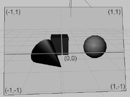
Figure 7–2. The near clipping plane (also known as the projection plane) and its coordinate system
Note that the coordinate system is by no means fixed. We can manipulate it so that we can work in any projected coordinate system we like; for example, we could instruct OpenGL ES to let the origin be in the bottom-left corner, and let the visible area of the “retina” be 480 units on the x-axis, and 320 units on the y-axis. Sounds familiar? Yes, OpenGL ES allows you to specify any coordinate system you want for the projected points.
Once we specify our view frustum, OpenGL ES then takes each point of a triangle and shoots a ray from it through the projection plane. The difference between a parallel and a perspective projection is how the directions of those rays are constructed. Figure 7–3 shows the difference between the two, viewed from above.
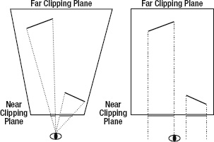
Figure 7–3. A perspective projection (left) and a parallel projection (right)
A perspective projection shoots the rays from the triangle points through the camera (or eye, in this case). Objects further away will thus appear smaller on the projection plane. When we use a parallel projection, the rays are shot perpendicular to the projection plane. In this scenario, an object will maintain its size on the projection plane no matter how far away it is.
Our projection plane is called a near clipping plane in OpenGL ES lingo, as pointed out earlier. All of the sides of the view frustum have similar names. The one furthest away from the camera is called the far clipping plane. The others are called the left, right, top, and bottom clipping planes. Anything outside or behind those planes will not be rendered. Objects that are partially within the view frustum will be clipped from these planes, meaning that the parts outside the view frustum get cut away. That's where the name clipping plane comes from.
You might be wondering why the view frustum of the parallel projection case in Figure 7–3 is rectangular. It turns out that the projection is actually governed by how we define our clipping planes. In the case of a perspective projection, the left, right, top, and bottom clipping planes are not perpendicular to the near and far planes (see Figure 7–3, which shows only the left and right clipping planes). In the case of the parallel projection, these planes are perpendicular, which tells OpenGL ES to render everything at the same size no matter how far away it is from the camera.
Normalized Device Space and the Viewport
Once OpenGL ES has figured out the projected points of a triangle on the near clipping plane, it can finally translate them to pixel coordinates in the framebuffer. For this, it must first transform the points to so-called normalized device space. This equals the coordinate system depicted in Figure 7–2. Based on these normalized device space coordinates, OpenGL ES calculates the final framebuffer pixel coordinates via the following simple formulas:
pixelX = (norX + 1) / (viewportWidth + 1) + norX

pixelY = (norY + 1) / (viewportHeight +1) + norY
Where norX and norY are the normalized device coordinates of a 3D point, and viewportWidth and viewportHeight are the size of the viewport in pixels on the x- and y-axes. We don't have to worry about the normalized device coordinates all that much, as OpenGL will do the transformation for us automatically. What we do care about, though, are the viewport and the view frustum.
Matrices
Later, you will see how to specify a view frustum, and thus a projection. OpenGL ES expresses projections in the form of matrices. We don't need to know the internals of matrices. We only need to know what they do to the points we define in our scene. Here's the executive summary of matrices:
- A matrix encodes transformations to be applied to a point. A transformation can be a projection, a translation (in which the point is moved around), a rotation around another point and axis, or a scale, among other things.
- By multiplying such a matrix with a point, we apply the transformation to the point. For example, multiplying a point with a matrix that encodes a translation by 10 units on the x-axis will move the point 10 units on the x-axis and thereby modify its coordinates.
- We can concatenate transformations stored in separate matrices into a single matrix by multiplying the matrices. When we multiply this single concatenated matrix with a point, all the transformations stored in that matrix will be applied to that point. The order in which the transformations are applied is dependent on the order in which we multiplied the matrices.
- There's a special matrix called an identity matrix. If we multiply a matrix or a point with it, nothing will happen. Think of multiplying a point or matrix by an identity matrix as multiplying a number by 1. It simply has no effect. The relevance of the identity matrix will become clear once you learn how OpenGL ES handles matrices (see the section “Matrix Modes and Active Matrices”)—a classic chicken and egg problem.
NOTE: When we talk about points in this context, we actually mean 3D vectors.
OpenGL ES has three different matrices that it applies to the points of our models:
- Model-view matrix: We can use this matrix to move, rotate, or scale the points of our triangles (this is the model part of the model-view matrix). This matrix is also used to specify the position and orientation of our camera (this is the view part).
- Projection matrix: The name says it all—this matrix encodes a projection, and thus the view frustum of our camera.
- Texture matrix: This matrix allows us to manipulate texture coordinates (which we'll discuss later). However, we'll avoid using this matrix in this book since this part of OpenGL ES is broken on a couple of devices thanks to buggy drivers.
The Rendering Pipeline
OpenGL ES keeps track of these three matrices. Each time we set one of the matrices, it will remember it until we change the matrix again. In OpenGL ES speak, this is called a state. OpenGL keeps track of more than just the matrix states though; it also keeps track of whether we want to alpha-blend triangles, whether we want lighting to be taken into account, which texture should be applied to our geometry, and so on; in fact, OpenGL ES is one huge state machine. We set its current state, feed it the geometries of our objects, and tell it to render an image for us. Let's see how a triangle passes through this mighty triangle-rendering machine. Figure 7–4 shows a very high-level, simplified view of the OpenGL ES pipeline.
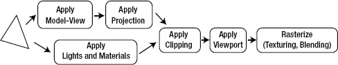
Figure 7–4. The way of the triangle
The way of a triangle through this pipeline looks as follows:
- Our brave triangle is first transformed by the model-view matrix. This means that all its points are multiplied with this matrix. This multiplication will effectively move the triangle's points around in the world.
- The resulting output is then multiplied by the projection matrix, effectively transforming the 3D points onto the 2D projection plane.
- In between these two steps (or parallel to them), the currently set lights and materials are also applied to our triangle, giving it its color.
- Once all that is done, the projected triangle is clipped to our “retina” and transformed to framebuffer coordinates.
- As a final step, OpenGL fills in the pixels of the triangle based on the colors from the lighting stage, textures to be applied to the triangle, and the blending state in which each pixel of the triangle might or might not be combined with the pixel in the framebuffer.
All you need to learn is how to throw geometry and textures at OpenGL ES, and to set the states used by each of the preceding steps. Before you can do that, you need to see how Android grants you access to OpenGL ES.
NOTE: While the high-level description of the OpenGL ES pipeline is mostly correct, it is heavily simplified and leaves out some details that will become important in a later chapter. Another thing to note is that when OpenGL ES performs projections, it doesn't actually project onto a 2D coordinate system; instead, it projects into something called a homogenous coordinate system, which is actually four dimensional. This is a very involved mathematical topic, so for the sake of simplicity, we'll just stick to the simplified premise that OpenGL ES projects to 2D coordinates.