
Now that we have a better understanding of the tool, we can create a definition of the sprint management process introduced in Chapter 3, Using BPMN 2.0 to Model Business Scenarios. To explain the biggest variety of elements, we will use the third version of the process we defined, which is the most complex. Please refer to Chapter 3, Using BPMN 2.0 to Model Business Scenarios, if you need to refresh any information about what the process definition contains. The idea is to know how to create the diagram shown in the following figure:

We'll continue working on the sprintManagement process definition. We will move the cursor over the predefined start node and select the Task option from its contextual menu (which should be the small rectangle with the rounded corners). This option will add a new task that is connected to the Start Event node in the editing canvas. We can repeat these steps, adding gateways (rhomboids) and sequence flows (arrows) when needed, by clicking on the rhomboid and rectangle icons on the context menu we previously described and by clicking-and-dragging on the arrow icon to create sequence flows connecting existing objects. Finally, we can create an End event node by clicking on the circle icon of the context menu with the thicker border.
When getting to the point where we need catching events and boundary events, we can search for them in Shape Repository by clicking on the left-hand side accordion panel, selecting from the different menus available (Tasks, Gateways, Intermediate Catch Events, and so on), and dragging-and-dropping a specific element into the editing canvas. We can drop the boundary events on the border of each task (you will see that the border of the task becomes green to indicate you can drop the catching event as a boundary event). Later on, selecting those intermediate events will allow us to continue adding components from their respective contextual menus of each element in the editing canvas.
We will start our process definition configuration by populating the mandatory attributes of the process itself. To do this, we have to click on the background of the editing canvas and go to the Properties panel, located at the right-hand side of the designer in an accordion panel. Each process definition has the following jBPM6-related properties:
Now that we have a clear idea of the properties a process has, we can see some extra details about some of them.
For example, the ID of the process has quite an important role. As it will identify the process definition inside a KIE base, we are going to depend on it to start a process or to define a Call Activity node (reusable subprocess). In our case, we will set the ID for this process as sprintManagement-V1.
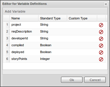
Finally, we need to define the process variables required by this definition by editing the Variable Definitions property of our process. When we click on the list box display of the property value, an editor will show us the dialog box as shown in the following screenshot, where we can add, remove, and define the name and type of our process variables. In the process we are designing, we need six variables: project, reqDescription, and developerId of type String; compiled and deployed of type Boolean; and storyPoints of type Integer. The final result should be as shown in the following screenshot:
Once we have the process configured, we need to review each of the nodes it has in order to configure their properties.
The Start Event node represents the beginning of the process. From all the different Start Event types that we can use, we will use the None Start Event node, because in jBPM6, you have to use this type of Start Event when your process is going to be explicitly started using its ID, as the following line of code does:
Ksession.startProcess("id.of.the.process");The properties present in this node relevant to the jBPM6 runtime are as follows:
Given that this None Start Event node doesn't have any properties that affect its behavior during execution, we are not going to modify any of them.
After the Start Event node is invoked, a process execution will be started. During the process execution, we might capture two other types of events, Signal Intermediate Catch events (the circle with a triangle inside it at the bottom of the diagram) and Error Boundary events (the two circles with the lightning-like icon, located at the border of two of the tasks we defined).
Intermediate Signal Event nodes have to wait for an event to arrive in order to continue their execution. Events can be broadcast from another process or from the Java application. Using them allows us to create more maintainable and robust processes. The properties we can configure a Signal Intermediate Catch event are as follows:
In our scenario, the event we are going to be waiting for is the manual cancellation of the requirement, which is why we need to change the SignalRef property to reqCancelled. To do so, we select the event and then click on the Properties panel, where we will see the properties of the event selected. In this case, we don't want to know anything else from the event, so we are not going to define any DataOutput or DataOutputAssociations property in this node. The only other change we are going to make to this node is to add a meaningful name to it so that users reviewing this process can easily understand what event the node is waiting for. The value we are going to set for the Name property is: Req. Cancelled.
The Error Boundary events that we defined for two of our tasks show that we want to handle exceptions being thrown inside the execution of said tasks as part of the sequence of steps in this process. Just like the Signal events, they have DataOutput and DataOutputAssociations to capture the event being sent. In them, you define a single variable with any name that you can map to a process variable to keep the exception as a variable in subsequent nodes. For our case, we are not going to configure those properties.
The one property we are going to configure is the
ErrorRef property. In it, you must write the fully qualified name of the exception you expect to capture. In jBPM6, it must be a single specific type (not a generic super class of the exception, but the actual exception), and it must have a fully qualified name even if you added the exception type to the Imports property in the process properties. For our case, we will type java.lang.RuntimeException in said property.
The last event nodes that we will configure in our process are the End Event nodes, which represent the end of the execution path on the process. We can configure them for many different purposes, but in our case, we will use only a type that will terminate the complete process instance (the Terminating End event), regardless of how many pending execution paths may still exist for both execution paths that diverge from the first parallel gateway.
The task nodes in BPMN 2.0 are where concrete actions take place. The steps that are required to achieve our process' goal are going to be defined using task nodes.
The BPMN 2.0 specification provides eight task types (Abstract task, Service task, Send task, Receive task, User task, Manual task, Business Rule task, and Script task), and jBPM6 supports all of them.
We will focus on the valid set of properties that affect each of the different tasks supported by jBPM6, but we are not going to cover the detailed behavior of the tasks at runtime.
In the Web Process Designer, all of the different types of tasks are implemented by just one element in the Shape Repository panel—Task. The TaskType property of each node is going to specify its concrete type. An empty value for TaskType (the default value in the Web Process Designer) identifies an abstract task.
Each task type has a different set of attributes that we can use to configure it. The Web Process Designer will automatically show only the valid attributes for each specific task type. The following table explains the valid properties for each type:
Abstract tasks are used by jBPM6 as an extension point for plugging in our business-related logic. DataInputSet, DataOutputSet, Assignments, On Entry Action, and On Exit Action are the properties common to all other types of tasks and have the same behavior for all of them. We will omit them in the next tables and concentrate exclusively on the extra properties that each task type has:
|
Business Rule task | |
|---|---|
|
Property |
Description |
|
|
This property is used to specify the group of rules that must be executed when the process execution reaches this node. |
In jBPM6, the Drools rule engine performs rule execution. These two frameworks, jBPM6 and Drools, are so well integrated that the switch from one engine to the other is seamless for the user. Actually, the switch has never existed since both engines share the same core.
The following table shows the Send task's special properties:
DataInputSet is especially important for the Send task, as it will map the message to be sent from the process variable.
The following table shows the Receive task's special properties:
DataOutputSet is especially important for the Receive task, as it will map the message received.
The following table shows the Script task's special properties:
Business users do not commonly use Script tasks, but they are really helpful for technical people. By adding Script tasks to a process, we can easily modify the behavior of our processes without modifying any Java class. We can use this type of task to add logs, messages, or to perform data transformation tasks in our processes. As a rule of thumb, Script tasks shouldn't contain business logic inside them. Abstract tasks, Human tasks, and Service tasks are better places to implement this kind of logic. Let's start with the Service tasks as shown in the following table:
User tasks are the ones that should be performed by humans:
The properties of the User task are tightly related to the default Human task implementation of jBPM6. This implementation is going to be introduced and explained in Chapter 6, Human Interactions.
Manual tasks have the same attributes explained for an Abstract task. The variables you can define in the DataInputSet and DataOutputSet properties depend on the handlers you register for Send, Receive, User, and Manual tasks. We have discussed work item handlers in Chapter 2, BPM Systems' Structure. User tasks will have work item handlers defined with the key Human Task, Manual tasks with the key Manual Task, Send tasks with the key Send Task, and Receive tasks with the key Receive Task—all configurable from the runtime configuration of the different WorkItemHandler implementations, which we have seen in Chapter 2, BPM Systems' Structure.
Going back to our process, we have six different tasks to define—one Business Rule task (assign story points), one User task (develop requirement code), and four Abstract tasks (notify developer of errors, notify developer of requirement changes, compile project to Maven, and deploy compiled project). Let's now configure this process definition to achieve the goal defined in Chapter 3, Using BPMN 2.0 to Model Business Scenarios.
For the first task, the first thing we need to do is change its TaskType property to a Business rule. A little icon similar to a table will appear in the node. We then need to change the Ruleflow Group property. This property defines the group of rules to be executed when this node is reached. The value we need for this property is assign-story-points. Finally, we will assign "story points" to the Name property.
Regarding the second task, we need to configure it as a User task using its TaskType property. A small icon of a person will appear in the node. The Name and Task Name properties for this task should be set to "Develop Requirement Code". For the Groups property, we will use "developers"; this represents the possible users that could own this task (the ones that belong to the developers group).
Now, it's time to configure the input and output variables for this task. As you may recall from the original definition in Chapter 3, Using BPMN 2.0 to Model Business Scenarios, this task has two input variables: complexity of type Integer and requirement of type String. With the DataInputSet property editor, we can define these input variables to look like the following screenshot:

The GroupId input is automatically generated by the editor when you fill the Groups property in the Properties panel for a User task. A similar thing is done for the Actors property with the ActorId input and output. We will use this to our advantage and define ActorId as a data output to obtain the actual user that performed the User task, as shown in the following screenshot:

Once we have defined all of our input and output variables, we need to make assignments between the process variables (or fixed values) and the input variables of the task as well as assignments between the output variables of the task and the process variables. This operation is performed in the editor available for the Assignments property of the task. Using this editor, try to create the configuration as shown in the next screenshot. You will find the From Object fields and the To Object fields that provide you with selectable options. To see all the options needed, you will need to complete the Variable Definitions property of the process, as we have seen in the Configuring the process properties section. Have a look at the following screenshot:

Before we continue, let's explore this editor in greater detail. An assignment is composed of three columns: From Object, Assignment Type, and either To Object or To Value.
For input assignments—which means the value we want to assign to one of the input variables of the task—we have to decide whether we want to assign a fixed value to it or if we want to map a process variable to it.
In the case of a fixed value, in the From Object column, we have to select the input variable that we want to assign from the drop-down list that contains all of the data input and output variables and process variables. The Assignment Type value required to assign a fixed value to a variable is is equal to. The third part of the assignment when we are assigning fixed values to an input variable is defined in the To Value column, where we have to enter the value we want to assign to the input variable. If what we want to do is map an existing process variable into one of the input variables of the task, we need to select the process variable first in the From Object column. Then, we have to select is mapped to for the next column, and finally, we have to select the task's input variable that we want to be assigned in the To Object column.
For output assignments, in the From Object column, we have to select the output variable we want as the source of the assignation. In the Assignment Type column, is mapped to is the only valid value, as we can't map an output variable to a fixed value. Because we can't use is equal to as the Assignment Type column, the only column we can use for the third part of the assignment is the To Object column, where we have to select the process variable we want to use as the target of the assignment.
All the other tasks in our process are Abstract tasks. We'll learn how jBPM6 uses these tasks as an extension point after we see another editor later in this chapter, so for the moment, we will only configure them as Script tasks, selecting that option in their Task Type property. For the properties of these tasks, we will edit the Script property and just write a simple piece of code to see whether the node is executed:
System.out.println(kcontext.getNodeInstance().getNodeName());
This will print out the node name through system output when the node is reached. This can be done quite fast if you select all the tasks where you want to edit the same property. The Properties panel will show only common properties between those tasks and allow you to change their values at the same time. Skip adding the boundary events until we explain custom task types.
In the case of gateways, there are not too many properties we can configure. The behavior of a gateway is determined by its type, which we have implicitly defined by selecting the specific gateway we want to use—XOR, also known as exclusive.
The Web Process Designer supports four types of gateway nodes, exclusive (XOR), parallel (AND), inclusive (OR), and event-based gateway nodes, and the properties they can have are as follows:
We are not going to set the value of any of those properties for our gateways, because they are there just to provide converging points, not to diverge flows. Configuring diverging flows from a gateway is done inside the sequence flows.
Sequence flows are the elements used to connect the Activities, Events, and Gateways in our processes. Only the following two sequence flows' properties have an impact on the jBPM6 engine:
As we are not using any diverging inclusive or exclusive gateway in the process that we are designing, there is no need to modify either of these properties in any of the sequence flows we have.
Before we can open an existing process in the KIE Workbench, we first need to find it. In the KIE Workbench, there are two different ways to search for an existing process: through the Project Explorer section in the Project Authoring perspective's left-hand side or through the Search… textbox on the right-hand side of the action toolbar.
The Project Explorer will give us (by default) an accordion-based view of all possible assets, split by asset type. Processes will reside in the Business Processes tab. We can change this by clicking on the gear button next to the Project Explorer title and selecting the Repository View option to see all files with their extension type and to browse subfolders.
If you're not sure where you stored the process you're searching for, you can use the Search… textbox to search by the name or part of the process name. A list with links to different matches will appear in the editor panel. Each one will have an Open button that we can use to open the desired process in the Web Process Designer.
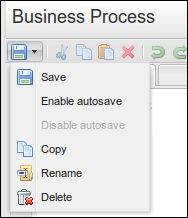
Once we have a process opened in the Web Process Designer, we can start working on it. For the rest of this chapter, we are going to cover the most important options and features to do this editing. When we want to save the changes we have made in a process, we have to use the disk icon that appears on the topmost bar of the process designer panel, and we can select Save to store changes, Enable autosave to continuously store any changes we make, or Delete to remove the process from the project (shown in the following screenshot):
By now we should have a process definition ready to be executed in the jBPM6 engine if we've correctly followed all of the steps so far. We should save the process by clicking on the Save button at the top-left corner of the designer screen and clicking on the Save option when the drop-down menu appears. We have two ways to test our processes: running process simulations in the designer or writing a unit test in Java code.
The Properties panel provides different sets of properties for different situations. By now, we are familiar with the core properties (the ones shown by default), but there are also extra properties for the least common core properties, graphics properties for color selections, and another set for statistical analysis of process models over time, the simulation properties. On these properties, we will define statistical information for our processes, tasks, and flows, which will later on allow us to determine the costs of our process executions, possible bottlenecks, statistical distribution, and likeliness of each path to execute.
We won't be able to get into the details of all of the simulation properties, but we will mention that they allow us to configure how much time each task can take with properties that will be determined by the statistical distribution of each task. Also, for diverging flows, they will allow us to determine the probability of following each different path. After that configuration is done for each task, we can execute simulations by clicking on the simulations icon shown in the following screenshot, and by configuring two parameters—the number of instances that will be simulated to run, and at an interval of time (specified by a number and a time unit).

The results of the simulations will be then shown in the Simulations tab, located in the top-left corner of the editing canvas. Simulation results include graphics and tables, with probabilities of each path, associated costs for each task, and resource utilization and idle times.
If we look for a project called process-examples inside the chapter-05 folder, we'll see that it contains a test file called SprintManagementV1Test.java. It uses a file called sprintManagementV1.bpmn2 that contains the definition of the process. So, basically, the test will execute the process definition to check that everything is working as expected. If you want, you can take a look at the source code of the test. We will now look at the important parts of the SprintManagementV1Test class, where we test how the process we just defined executes in the following code:
KieSession ksession = createKieSession();
TestAsyncWorkItemHanlder h1 = new TestAsyncWorkItemHandler();
TestAsyncWorkItemHanlder h2 = new TestAsyncWorkItemHandler();
TestAsyncWorkItemHanlder h3 = new TestAsyncWorkItemHandler();
ksession.getWorkItemManager().registerWorkItemHandler(
    "Human Task", h1);
ksession.getWorkItemManager().registerWorkItemHandler(
    "compiler", h2);
ksession.getWorkItemManager().registerWorkItemHandler(
    "deployer", h3);
Map<String, Object> params = new HashMap<String, Object>();
params.put("project", "MyProject");
params.put("reqDescription", "My new Requirement");
ProcessInstance instance = ksession.startProcess(
    "sprintManagement-V1", params);
In the preceding code, we first created our session (using the APIs we saw in Chapter 2, BPM Systems' Structure), named ksession, and we registered work item handlers for it. The main process activity starts when we call the startProcess method, which receives the process ID we defined and a map of parameters (whose keys, you might notice, were described in the Variable Definitions property of our process). This is the most basic API we will need on the runtime to start a process instance.
Up to this point, we have learned to create and manage process definitions in the KIE Workbench. We have also covered the steps required to design a process from scratch using the elements available in the Web Process Designer's palette. We have covered the most frequently used elements that jBPM6 supports, but we still might need to get a better understanding of the rest of the nodes. I strongly recommend reading the jBPM6 user guide, especially the chapter on the Web Process Designer. It can be found at http://docs.jboss.org/jbpm/v6.0.1/userguide/.
Also, for a full reference of all the designer features, you should refer to its documentation at http://docs.jboss.org/jbpm/v6.0.1/userguide/chap-designer.html.