
After learning about the BPM discipline, we understand that we need to have a formal language to express our business processes. This language will help us in defining a well-established sequence for the decisions our organization makes. We want to make sure such definitions are as powerful as possible, so we want the formal language to be extensible. We also want the freedom to choose our BPM system regardless of our definitions as much as possible, so we want the formal language to follow widely accepted standards. For all these reasons, in this chapter we focus on BPMN 2.0, a standard, flexible language that is supported by jBPM6 and many other providers as the current de facto language for executable business processes.
We will introduce a real-life use case to demonstrate best practices and design strategies based on managing requirements in a Sprint Development use case, where we will perform the following operations:
- Introduce the BPMN 2.0 standard specification
- Model different elements of our business processes
- Create an example to run our processes
We will be covering most of the most common constructs required to model and build real-life processes. You might already have a particular use case, so if you do, try to use such constructs and best practices for your particular scenario. The concepts we'll learn in this chapter apply for virtually any domain.
The idea behind BPMN Version 2.0 is to provide a standard way to both represent the visual structure of a business process and its execution semantic, all in the same file, while also providing a mapping between both. This way, the gap between business analysts drawing a new business process and the business process actually running in an execution environment is significantly reduced. This also provides a common ground for technical people and business people to share ideas. The purpose of this chapter, and of the BPMN standard, is to make process diagrams (such as the following diagram), something that can be easily read and understood by different groups of people:

The standard was formally released in January 2011, and it is a result of the collaboration between companies such as Oracle, IBM, Red Hat, Intalio, and many others within the Object Management Group (OMG). They combine almost 20 years of business process standardization experience in this standard. This specification (Version 2.0) is divided into four sections that allow different vendors to comply with one or more of the following compliance types:
- Process modeling
- Process execution
- Collaboration modeling
- Choreography modeling
In this book, we will cover only process modeling and process execution because jBPM6 focuses only on those areas.
Process modeling only needs to worry about the visual representation of the business process to comply with that part of the BPMN 2.0 standard. This usually provides graphical tools to draw/model business processes and collaboration diagrams. The specification defines two types of business processes:
- Non-executable
- Executable
Modeling tools only need to model non-executable processes, but they can also add all the details necessary to make the process definitions they create executable in different environments.
Non-executable processes are something to still take into account. In a sense, all processes start as non-executable processes until all the details necessary for their proper execution are added in a BPMS environment. Non-executable processes can also be very useful for documentation, sketching, and as common ground to discuss the internal processes of an organization.
If we want to model executable processes, the specification creates a subcategory (such as a subclass) of this compliance type called Common Executable Conformance, covering the minimum requirements for an execution environment for executable business processes. These requirements are as follows:
Of course, different vendors can decide how to cover these requirements—by changing technology stacks on different points or adding new possible implementations. It is a good point of comparison between vendors to see what features each vendor implements and how they implement them.
Now, we will explain all the different components that the BPMN 2.0 standard defines for process modeling and execution. We will also mention how jBPM6 adheres to this standard. For the full specification of BPMN Version 2.0, you can visit http://www.omg.org/spec/BPMN/2.0.
In the next section, we will use those concepts to define example processes that will help us fully understand how all the concepts work together.
The specification divides elements in the process definition as follows:
- Flow elements
- Connecting elements
- Data
- Swimlanes
- Artifacts
Flow elements are one of the most important elements, as they are in charge of defining behavior. The specification defines three types of different flow elements: events, activities, and gateways. Each is in charge of very different kinds of steps, and therefore all very necessary to define a complete business process.
Events
Events represent a capture of a particular occurrence that interests the process. They are usually caused by an external cause or trigger. They're represented with a circle and, depending on the type of the border and its contents, the behavior that events expect to trigger. In the following diagram, we see an example of different BPMN events with types and subtypes:
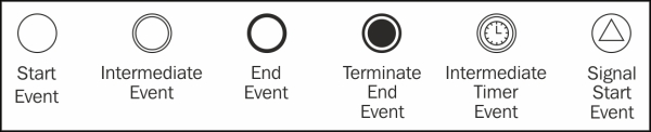
There are three main types of events:
- Start events: These events are drawn with a single, thin border line. They represent an external interaction that causes the beginning of a business process instance.
- Intermediate events: These events are drawn with double, thin border line. They are in charge of catching external events or throwing events, even outside the process instance scope. They can influence the flow of the process, but they cannot start it nor end it.
- End events: These events represent the end of a process instance or the end of an execution path inside a process instance. It is always sent and never received from outside the process instance scope.
For each main type of event (start event, intermediate event, and end event), there are many subtypes defined by the specification. For example, the last three events in the previous diagram are specific subtypes. The terminate end event marks that all the active execution paths in the process instance must finish, as long as one path reaches said node. The intermediate timer event will wait for a given amount of time before continuing with the execution flow. Finally, the start signal event will start a new process instance when an external signal of a specific kind is sent to the runtime environment. There are many more; but for the first examples we'll see, these will suffice. Support for a wide variety of all three main types of events is provided by jBPM6.
Activities
Activities define a piece of work that is being done inside the process scope. They could be atomic or nonatomic activities, depending on whether they can be further divided into more activities or not. For such purposes, the standard defines three different types of activities: tasks, subprocesses, and call activities. These are represented as boxes in the following diagram:

As seen in the preceding diagram, a rounded rectangle defines a task, which can have different subtypes. An icon on the top-left corner can define different types of atomic activities, such as User tasks (a human should provide a specific input in these kind of tasks), a Script task (when a particular piece of script needs to be executed), a generic task (it will have no icon and is thought to be defined in runtime), or many more.
When the rounded rectangle has a particular sign on the bottom, the activity is considered as a subprocess, which means that it can be decomposed into different activities. Depending on the sign, it can mean that the round rectangle will contain many subactivities that are just not relevant to the current process definition's scope. This can be executed once (when it is a plus sign) or many times (when three parallel lines are on the bottom). Usually, these subactivities are embedded inside the subprocess activity box.
Finally, if we want to invoke a process definition defined outside the scope of the current process, we use call activities. This encourages reutilization and transfers the control of the execution to the activity being called. Call activities are defined by a thicker border line, like the third rectangle from left in the previous diagram.
All of these types of activities, tasks, subprocesses, and call activities are supported by the jBPM6 process designer at runtime.
Gateways
Gateways control the divergence and convergence of sequence flows in a process. They are represented by a rhombus, and the drawing inside the rhombus determines the different types. The following diagram shows examples of different BPMN gateways:

BPMN2 gateways have one outgoing connection and many incoming connections (when a gateway is diverging), or many outgoing connections and one incoming connection (when a gateway is diverging). The most commonly used gateways are as follows:
- Exclusive (or XOR-based) gateway: This is marked with an X sign and it allows only one outgoing execution path to be executed, depending on conditions defined in the outgoing flows. When converging, it carries on whichever path reached it, because it expects one flow to be executing only.
- Parallel (or AND-based) gateway: This is marked with a plus sign and allows us to define concurrent paths. When diverging, it creates a new execution path for each outgoing connection; when converging, it waits for all connections to finish and carry on with one execution path.
- Inclusive (or OR-based) gateway: This is a less restrictive version of the exclusive gateway. It allows one or more paths to continue when diverging, depending on conditions defined in the outgoing flows. When converging, it should wait for all active paths to finish before continuing with a single execution path.
- Event-based gateway: This defines a branching point in the process where we should wait for one of many different events before continuing with the process execution. Event-based gateways allow the process to make a decision on which path to follow based on the event received first.
- Complex gateway: This allows us to define a more complex condition, where 1 to n branches should be able to continue. When joining branches, we can also decide whether to wait for one or more execution paths before continuing with the next activity of the process.
Complex gateways are the only ones not supported by jBPM6. Also, for converging gateways, only exclusive and parallel gateways are supported.
To define the sequence between flow objects, we use sequence flows. They are represented as arrows, and the specification defines three types of sequence flows to specify different behaviors to propagate the execution. The following diagram shows different sequence flows:

The different sequence flows are defined as follows:
- Uncontrolled sequence flow: This is the most common sequence flow. It represents a connection between two flow objects, with an origin and a destination.
- Conditional sequence flow: This evaluates an expression to determine whether it should continue to the next flow object or not. The expression is evaluated at runtime when the process is being executed, usually involving a check on a process variable.
- Default sequence flow: This is used in inclusive/exclusive/complex gateways. It determines the flow that will be selected if no other path matches the specific criteria.
Sequence flows are the standard way of providing a sequence in business processes, and they are fully supported by jBPM6.
Finally, the relationship between these data components, the process, and its flow objects is done using message flows. They represent an association between a data object and a flow object. The specification mandates that message flows don't affect the process execution flow, and they only provide a way to share information between a source and a target. The specification also allows transformations to be applied by using expressions, as shown in the following diagram:

Data elements represent information that will be manipulated by the process instance during its execution. BPMN 2.0 allows us to define this information graphically and to specify where the data will be used. Data objects can be divided into the following:
- Data objects
- Data inputs and data outputs
- Data stores
- Properties (no visual representation)
Data objects are the most basic representation of a piece of information used in a process. They can be added to processes and subprocesses and can be associated with their life cycle. That means, when our processes are instantiated, we can instantiate our data objects as well. We can mark data objects to be a single instance or a collection, as shown in the following diagram:

The other two types in the preceding diagram are also data objects, but they are called data inputs and data outputs. They map specifically to inputs or outputs of a specific activity.
Data stores are used to interact with information outside the scope of the process. They represent external sources of information that are not instanced by the process, but that the process execution can access nonetheless, that is, a database. The following diagram shows the Data Store:

Properties include data objects, but those that have no visual representation. They are pieces of information that can be associated with processes and flow objects. Depending on where the properties are defined, some parts of the process can or cannot access said properties. Process properties can be made accessible to all the activities inside the said process. Activity properties can only be accessed inside the same activity.
Data stores and data objects are supported by the jBPM6 parser, but no runtime configuration is provided for them. Data objects are mapped in jBPM6 as process variables. Activities' inputs, outputs, and process variables, are usually represented as properties, mainly because jBPM6 doesn't support message flows to correlate specific data objects to inputs or outputs of a specific component.
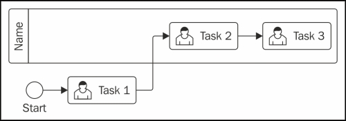
Swimlanes are defined to organize and categorize the activities that belong to a process. Using swimlanes, we can denote responsibility from a role or a business unit to a set of activities. Most of the time, they are used to improve process readability.
From the jBPM6 implementation, swimlanes are used to define a particular group of User tasks (see the Task types in jBPM6 section later in this chapter) that should be performed by the same user. In the following example, Task 3 has to be performed by the same user who executed Task 2:
Artifact elements add additional information to diagrams. They're used to improve documentation aspects and the specification defines two types of artifacts: Groups and Text annotations.
Groups are used to encapsulate a group of tasks together by any sort of criteria. They don't affect the flow of the process. Text annotations allow us to add notes to our process diagrams, such as comments inside our process, as shown in the following diagram:
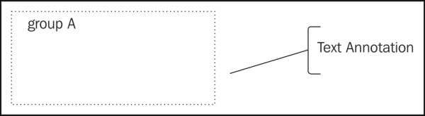
Since they don't affect process execution, jBPM6 skips them from its internal parsing.
As we previously mentioned, one of the most important types of flow objects is the activity. Each activity will represent a task related to our business scenario. The specification provides a set of specific tasks that can be used to define different behaviors. This section covers the most commonly used tasks that we need to know in order to start modeling our business scenario. The task types shown in the following diagram will be described in this section:

The tasks in the preceding diagram are defined as follows:
- Abstract task: This is the base type of all the other tasks in BPMN 2.0. According to the specification, this task is abstract and we should never use it in our processes. However, jBPM6 uses it as an extension point to introduce new task definitions. We will see how this is achieved in more detail in Chapter 5, Creating a Process Project in the KIE Workbench.
- Service task: This allows us to represent interactions with external automated systems. Each time our business process needs to interact with a service or procedure, we will use a service task. The service task element defines an attribute called implementation, which is used to specify the underlying implementation of the service that we are calling.
- User task: This represents a human interaction. Each time we want to represent a person doing an activity, we use a User task to model this situation. Because User tasks represent a human interaction, we need to provide a way to assist the performer during this interaction. The jBPM6-based BRMS provides a task list-oriented user interface that assists each user during these interactions. We will take a close look at this approach in Chapter 6, Human Interactions.
- Business Rule task: This allows us to interact with a Business Rule Engine (BRE) to do some business logic evaluation. The interaction with the BRE usually involves sending information to the Engine, which will be evaluated by a set of business rules and a result will be returned. In the case of jBPM6, integration with a business rule engine is already part of the process engine, so this integration becomes simple.
- Script task: This allows us to execute a script that can be specified in various languages. A script basically represents a set of actions that we can code using a scripting language. For jBPM6, the supported languages are Java and MVEL (http://mvel.codehaus.org).
Activities can represent aggregations of multiple other flow paths, called subprocesses. The reason behind grouping particular parts of a process together could be hiding or grouping additional levels of a business process in detail or specifying a completely different way to manage those paths. In the following diagram, we can see different icons that are used to define some of these subprocess types:

A basic subprocess (in its collapsed view) will be marked by a plus sign at the bottom. This is just to define that there is a different process definition inside this box. This type alone gives us a lot of power, because it lets us define a process definition hierarchy to define from the most atomic activities of our company to the general company drivers, all with different levels of processes.
Alongside the basic subprocess, there are other types of subprocesses. The most common ones are as follows:
- Multiple instance (MI) subprocesses: They define a subprocess that should be instantiated and executed multiple times from the external process instance. It comes in two flavors: Parallel (marked by three vertical lines at the bottom) and Sequential (marked by three horizontal lines instead). The iteration is done over a collection-based process variable in the external process instance. Both types are supported by jBPM6, but they are both treated as sequential.
- Ad-hoc subprocesses: This type of subprocesses is peculiar as it only contains activities, and there is no sequence defined. Every activity included in the subprocess can be executed in any order as long as specified completion conditions are fulfilled. Actually, the internal activities of an ad hoc subprocess might not even have to be executed at all to fulfill said conditions, making the whole subprocess optional. They are represented with a tilde (
~) marker at the bottom and are supported by jBPM6 through the dynamic node utilities://We need to start with a KieSession: KieSession ksession = ... //We start a specific process instance: ProcessInstance pI = ksession.startProcess( "dynamic-process"); //If the first node we wait at is an ad hoc subprocess, //the following code will return a node for it: DynamicNodeInstance node = (DynamicNodeInstance) ((WorkflowProcessInstance) pI). getNodeInstances().iterator().next(); DynamicUtils.addDynamicWorkItem(node, ksession, "Human Task", null);In the previous example, we used the
DynamicUtilsclass to generate an execution of one of the tasks in the ad hoc process called"dynamic-process". - Loop subprocesses: Similar to multiple instance subprocesses, the loop subprocesses will repeat themselves over and over again in sequence until a condition is met that stops the loop. The main difference with multiple instance subprocesses is that this type of subprocess is not dependent on a collection-based variable, but only on a specific finish condition. It is not supported by jBPM6.
- Compensation subprocesses: This is a specialized version that only happens when a specific kind of event called compensation is triggered. Compensation events are thrown when a process has done something that it shouldn't, but still has a chance of completing successfully. Compensation subprocesses are related to undoing steps that were already successfully completed, because their results and possibly side effects are no longer needed and need to be reversed. They are supported by jBPM6.
Events, as we saw earlier in this chapter, trigger or capture situations of special interest to our process, depending on their type (start, end, or intermediate catch or throw). Depending on what the situation is, we need to define specific subtypes of events that define different situations. There are too many subtypes to explain them all in this book. In the following diagram, we see a few of the most commonly used event subtypes:

Among the subtypes that we can distinguish in the previous diagram, the following events are present:
- Signal events: These events are used to send and receive signals. Signals are generic, simple forms of communication. They can be sent between activities and even be shared between different process definitions. They don't have a specific recipient, so any other component in the same runtime can receive a signal by just defining that they are listening. The jBPM6 API can send signals to a process from outside its scope using the
signalEventmethod:KieSession ksession = ...; ksession.signalEvent("signalName", null); - Timer events: These events are triggered by a defined timer. They must have exactly one element of the type
timeDate(to determine the specific date at which the event should be triggered),timeDuration(to specify after how much time it should trigger the event), ortimeCycle(to specify intervals at which the event should repeatedly fire). All three are supported by jBPM6. - Message events: They are similar to a signal event, except they are directed to a single receiver. It has an attribute called
messageRefthat defines a message to be sent. From the jBPM6 perspective, however, it can be received by any number of listeners, and handles itself through thesignalEventmethod as well. The code is as follows:KieSession ksession = ...; ksession.signalEvent("Message-messageRefName", null); - Error events: These events are prepared to handle specific errors that occur in a process execution. They can be used as end events to terminate a flow indicating an error occurred or used to catch specific errors. They can even be used to start a subprocess.
- Compensation events: These events are used to compensate for errors that occurred in the flow of a process. If you find yourself in a situation that shouldn't be happening, you can trigger a compensation event to notify the specific compensation handler (a catching compensation event) that an action should be taken to amend the execution somehow.
- Escalation events: These events are similar in implementation to compensation events. They mark a situation that cannot be handled anymore by the current process execution. The only difference with escalation events is that some higher scope of process execution (that is, a parent process) should handle the specific situation that fired the escalation event. That is why they can only use start and throw escalation events inside subprocesses.
- Terminate events: Processes can have multiple flows running in the same process definitions. The process instance is not considered completed until all active execution flows reach an end event. Terminate events are used to avoid this, since process instances are completed as soon as any of the execution paths of a process reach a terminate end event.
There are a few more that aren't covered by jBPM6 much or very widely used, so we skipped them from this book. We encourage you to look into the specification if you're interested in other types of events.
Boundary events are a very practical combination of two flow objects, activities, and events. When you assign an intermediate catch event to the border of an activity box, you determine events specific for that activity only. They are very useful for controlling the flow of tasks and subprocesses alike. The following diagram shows a few examples:

As the preceding diagram shows, you can capture escalations, errors, signals, and many other types of events being sent from an activity and divert flow accordingly. You can even have multiple boundary events on a single activity box. In the case of the preceding diagram, depending on whether Activity C sends a signal before or after a specific amount of time passes since the activity started, the flow might be diverted to two different steps.
The activity can still have a regular outgoing flow. For the first case in the preceding diagram, if no escalation is sent from Activity A, the process could continue through a sequence flow attached to the activity box directly.
Boundary events are a good way to manage alternate flows. Like all other components that add complexity to our processes, we must make sure that we don't make the process too complicated to be easily maintained.
Now that we had a brief overview of the different elements that compose the BPMN 2.0 specification, we can start seeing how they can be combined to define our own business processes. To do so, we have a couple of scenarios to analyze where we will see the different modeling options we have to execute them. We will also take a look at the XML generated by the modeler tool.