
The direct editing set of tools in SolidWorks enables you to change a part without the knowledge of how it was originally created. Direct editing works on both native and imported geometry by simply moving faces. There are two things to consider with direct editing: First is how direct edit tools work in SolidWorks, which is the main focus of this chapter; and second is how direct edit tools compare to the tools in history-free CAD software, which is a side issue but addressed as well.
This chapter exists partially because of recent direct editing developments in the CAD world and partially in honor of the new Direct Editing tab SolidWorks added to the CommandManager in the 2010 release, which is shown in Figure 30.1.
The new tab has the following tools on it, listed from left to right from Figure 30.1:
Additional direct edit tools exist in SolidWorks that should possibly be added to the Direct Edit tab:
Flex
Deform
Freeform
Combining these tools with some of the new Instant 3D functionality gives direct editing tools in SolidWorks many of the advantages of the direct edit—only CAD software. Before a discussion of direct editing will make sense, you need to know a little bit about imported geometry.
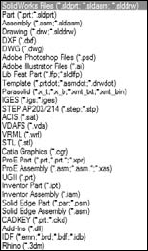
Geometry that is transferred between CAD packages is called imported geometry. The transfer usually happens through IGES (Integrated Geometry Exchange Standard; pronounced eye-jess), STEP (Standard for the Exchange of Product), Parasolid, or ACIS (named for the initials of three people from one company who created the standard: Alan, Charles, Ian, and Spatial) formats. SolidWorks also reads some native CAD data directly. For example, SolidWorks can read data directly from versions of Pro/ENGINEER, Unigraphics, Inventor, Solid Edge, CADKEY, and Rhino, as Figure 30.2 shows. In almost all cases, features are not transferred between CAD packages. The geometry that you wind up with is called "dumb" geometry because the smart parametrics and design intent that the model had in its parent software is no longer there.

You can use the new Data Migration tab in the CommandManager to find tasks that support imported geometry. The tools on this tab are shown in Figure 30.4.
Figure 30.4. SolidWorks 2010's new Data Migration tab on the CommandManager help you find import tools.
The tools on the tab, listed in order from left to right are
Open
Imported Geometry
Import Diagnosis
Check
Draft Analysis
Recognize Features (FeatureWorks)
Heal Edges
Knit
Move/Copy Bodies
Move Face
Delete Face
Replace Face
Split
Combine
Rip (sheet metal)
Insert Bends (sheet metal)
Many of these tools are not directly related to imports, but may be frequently used with imports. FeatureWorks is also a part of the SolidWorks Professional bundle, and as such is beyond the scope of this book; however, it is mentioned as part of one possible workflow for editing imported geometry toward the end of this chapter.
When SolidWorks imports data from another CAD program, the result is an Imported feature in the FeatureManager. The example shown in Figure 30.3 is the situation you are typically looking for: the result as a single solid body. Frequently, imports do not come in this clean. When imports start giving you trouble, you will see errors on a single body, or possibly multiple bodies, or even surface bodies. SolidWorks can address some types of errors automatically, you can address some manually, and you will probably want to avoid doing anything for some altogether.
The best way to start to feel comfortable with imported data is to be exposed to a wide range of files, some that work and some that don't. This chapter is not intended to be a short course on import repair, but repair is certainly part of the reality of working with imported data. When imports fail, it is not often because of SolidWorks; it is often because the parent software fails. SolidWorks import tools are very good and have improved over time.
When you import geometrical data into SolidWorks, you can get a number of different types of results:
Single solid body in a part file
Assembly of multiple parts
Multiple solid bodies in a part file
Surface bodies in a part file
Combination of solid and surface bodies in a part file
When you get an assembly of parts, SolidWorks uses the default template that you have designated in Tools
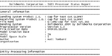
Some imports also create a report file with the extension *.rpt or *.err. This file includes statistics about the entities and precision of the data, filename, units, the originating system, and also some information about errors that occurred during the import.
Figure 30.5 shows the first section of a report written for the import of an IGES file.
I am going to import a few parts that don't come in perfectly and ask you to follow along with the files on your CD-ROM. This is not so much a click-by-click tutorial as a "watch over my shoulder" demonstration with commentary.
After you open the file, you will notice a couple of things. The first thing that stands out to me is that the model displays in Shaded mode, regardless of how you have the display set. For example, I like to use Shaded With Edges, but imports always set it back to Shaded.
In this case, the model really is clean. Running Import Diagnosis is the only way you can really know this. Figure 30.6 shows the FeatureManager, the Import Diagnosis, and the part itself.

Next, open the Parasolid file called bad face.x_t. This one also imports without an error or warning on the Import feature, but there is clearly a missing face. It is easier to visualize the separate faces of the part if you change the display mode to Shaded With Edges. If you examine the part closely, you can see that several faces are not lined up square with the rest of the part. Notice also that there are small sliver faces. This may be intentional, or it may be part of the problem. Triangular faces and sliver faces (with very sharp corners, usually long and narrow) are often the source of errors in translated parts.
Right-click the Import feature and run the Import Diagnosis; you will see the faulty face listed. Click the Attempt to Heal All button to fix the faulty face. Figure 30.7 shows the part with the faulty face.

Now open the Pro/ENGINEER file called bad face 2.prt.29. Pro/ENGINEER files often end with version numbers as the extension of the file. You need to be careful if you see a file that looks like a Pro/ENGINEER file with no version extension. SolidWorks used the *.prt extension for the first couple of years, and you may still find some of those parts in circulation.
Open the file using the Import Geometry Directly option, and switch the display to Shaded With Edges, and run an Import Diagnosis. The part has a bad face. If you click on the face in the Faulty Faces list, you can see that the face is next to a small, pointy triangular face, shown in Figure 30.8. The Attempt to Heal All option takes care of it.

Import the same file, but this time choose the Analyze the Model Completely option. It should tell you that it recognizes 13 out of 13 features. Click the Features button and watch the part rebuild. Notice that this time the part comes up with a feature error. The error is on a fillet. It is not an accident that the previous error was on a face next to a fillet face.
Notice that the Parasolid parts came up almost immediately, but the Pro/ENGINEER parts take several seconds to process the data. As the imported files become larger and larger and branch into assemblies, this difference becomes more and more pronounced.
The sheet metal features are added to the part, but notice in Figure 30.9 that they have failed. A close inspection of the part reveals that there is a small ledge between the big flat face and the inside bend on both ends. This was probably a modeling error rather than a translation error. You might be able to fix this to make it usable as a sheet metal part, but for imported geometry editing, you'll need to go to the end of this chapter. Here I cover the results of attempting to repair this model.

Figure 30.9. Very small errors can cause special functionality in SolidWorks not to work, and repairing it is not always straightforward.
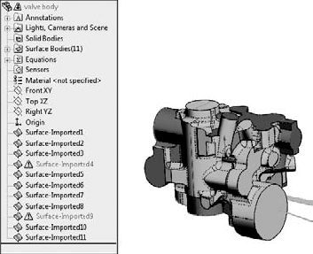
The last part I want to show in this "watch over the shoulder" demonstration is a part that I consider to be a complete loss. This is an IGES file that came from an Autodesk Mechanical product. In the CD-ROM, open the file called valve body.igs. This part takes several seconds to import. When it does import, it has 11 surface bodies, 2 of those with errors, and some obvious problems with a couple of faces that somehow became out of control. This is one of the reasons so many users do not recommend using IGES files. This type of error is more prevalent with IGES files than other formats. Figure 30.10 shows the FeatureManager and the part on the screen. Again notice that the location where the huge problem faces come off the model are pointy triangular faces.
Note
If you get an error that says "There are no points that exist in this file" when importing an IGES file, it is probably because you have Scan To 3D selected in your add-ins list. IGES is one of the accepted file types for bringing in point cloud data, and Scan To 3D assumes you are trying to use the IGES for that. Scan To 3D is an add-in that comes with SolidWorks Premium, not with SolidWorks Standard, so it is beyond the scope of this book. To disable it, choose Tools
If you get a part that is this bad, your first move should be to try to get better data from the source. If that isn't available, you are going to have an uphill battle trying to make this part work. Automatic healing with the Import Diagnosis isn't going to touch this part. Repair is going to be an exercise in manual surface modeling. If you don't have the patience for that, you could try solid modeling from the reference faces on the part. If you look closely at the interaction of some of the fillets, it is no surprise that the translation failed so badly. Many of the fillets are badly hacked together. In addition, if this is a casting, someone is going to need to apply draft to the part, and with all the fillets on it, this part is not going to lend itself to that very well.
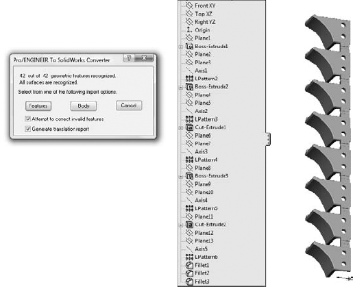
SolidWorks contains some direct converters that either extract the kernel data (Parasolid information) or read the actual feature data and rebuild feature-based parts. The direct converter for Pro/ENGINEER data is probably the most widely used. Figure 30.11 shows the dialog box for the Pro/ENGINEER to SolidWorks Converter.
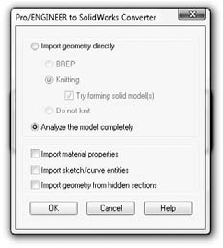
If you use the Import geometry directly option, you just get the dumb solid. Pro/ENGINEER uses its own "kernel," or underlying geometry engine, called Granite. SolidWorks shares its kernel with NX and Solid Edge (a Parasolid). To read the geometry directly, SolidWorks has to read the Granite data stored inside the Pro/ENGINEER file and translate it to Parasolid geometry.
If you choose the Analyze Model Completely option, you get a dialog box similar to the one shown in Figure 30.12. In this case, the Pro/ENGINEER part had 42 features, and the SolidWorks converter can read them all. Here too, you are given the option to take the features or the body. It is not clear that the Body option is the same as the Import geometry directly option, but they both result in the import of the dumb solid.
You would want to click the Body option if the percentage of recognized features was low, or if you didn't really need the parametric features that much. Sometimes, even if it doesn't recognize all the features, you might still get all the sketches you need to re-create the part.
Note
When parts are re-created in this way, sketches are not made dependent on faces of the model; instead every sketch will lie on a reference plane. This is very similar to the Wide Tree approach discussed in Chapter 11.
If you choose the Features option, SolidWorks rebuilds each sketch and feature to build a history-based model. This is not usually what people mean when they talk about imported geometry. Many CAD neophytes assume that features just automatically transfer from one CAD system to another, but this is by far the exception rather than the norm.
Figure 30.12 shows the Pro/ENGINEER to SolidWorks Converter dialog box and the finished imported model.
This translation depends on the version of the Pro/ENGINEER file. Check the SolidWorks documentation to see what versions of Pro/ENGINEER are supported.
Import errors are usually caused by differences between the exporting and importing CAD software vendors. Some imports are more prone to errors than others. For example, the IGES format is interpreted different ways by different software vendors, and is, therefore, very prone to errors.
Another type of error is the error due to tolerance or accuracy issues. Catia is notorious for having very large tolerances on exported data. This is to enable Catia to work with large data sets more easily, but it means that when the geometry is read into SolidWorks, which typically requires more accurate data, you can see a lot of errors. The fact that the Catia to SolidWorks translation is one of the most problematic in the CAD industry seems odd because SolidWorks and Catia are both owned by Dassault Systemmes, but the difficulties have persisted for more than a decade, so it is not a technological difficulty, it is a business decision.
SolidWorks has a tool called Import Diagnostics. Import Diagnostics can run automatically or manually to find the errors in imported data and to make repairs if possible. You can access Import Diagnostics by right-clicking an imported feature in the FeatureManager, as long as there are no native SolidWorks features that follow the imported feature. Figure 30.13 shows typical results from a faulty import.
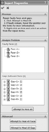
Sometimes the errors Import Diagnostics finds are things you can see, like missing faces, and sometimes they are things you can't see, like the edges of a face that don't intersect or inconsistent face normals. When errors can be found and repaired by Import Diagnostics, it is the best way to go. In fact, whenever I import a model, I always run Import Diagnostics on it to make sure everything is good.
Some errors are so big that the Import Diagnostics cannot fix them. An example of this type of error would be when a face is missing altogether from the imported data. When something like this happens, the only thing you can do is resort to surface modeling. If the import leaves you with surface bodies, and it cannot repair them automatically, you have to be able to remove the bad faces and replace them with new faces that you construct. This is all about using surface tools to create the new face, extending and possibly trimming the new face to fit into the gap caused by the bad face or faces, and then knitting everything together back into a solid. This may be an oversimplification of the workflow for manual import repair, but it is essentially the big-picture steps that you have to go through to get the task done.
There is such a thing as models that are so bad that you can't fix them, or that would not be worth your time to fix. If automatic repairs don't work, and simple manual repairs don't work, the next thing to do would be to go back to the source of the file and ask for better data.
When ever you export data to another CAD system, it is considered best practice (and professional courtesy) to "round trip" (save out, then read back in) the data to make sure that you can accurately read the data that you wrote out. You should not send someone else data that you cannot read back into the CAD system that created it. This may be of little comfort to you when you are the one receiving the bad data, but if you receive bad data, you have every right to go back to the creator and ask if he can round trip his data. It might be that he can adjust tolerance or accuracy settings to give you better data, or possibly that his model had some problems that he didn't know about when he exported it out to you.
If you get bad data and you do not have access to the source, and automatic and manual errors prevent you from using the data, then the next best thing is to rebuild the part using the error filled data as a reference. This is never a pretty thing, but if you really need the data to be clean, and there is no other way, this is what you need to do.
You can take measurements in one file and build a new part in another file, build one file in the context of an assembly directly over the problem file, or even rebuild it as a multi-body part.
Occasionally you can employ tricks to heal problem imports. Simply saving out of SolidWorks as Parasolid and reading back in repeatedly can sometimes heal troublesome imported geometry. I frequently use Rhino to import problem files, then export from Rhino as a Parasolid. Rhino is an inexpensive surfacing application. You can read more about it at www.rhino3d.com. You can download and install a trial version that allows you to save 25 times. Rhino works great as a translator because it reads and writes many file types that SolidWorks does not read. Sometimes when I get a very bad IGES file, I read it into Rhino, and save it out as Parasolid, then read the Parasolid into SolidWorks. Sometimes this will repair the data to the point that SolidWorks can deal with it more effectively.
This is not to say that Rhino is a better file translator than SolidWorks, because this workaround does not always improve things. It is sometimes effective, and because it is free, the only thing it will cost you to try it is time.
You can use the same trick with other CAD packages. For example, if you know that you have an IGES file from VX, and you are having difficulty reading it into SolidWorks, it might pay to download a trial version of VX (www.vx.com) and see if it can import the data and re-export. It is best to use the source program to read and re-export when possible.
If you can't get a SolidWorks file from someone who needs to send you data, the type of translation file that you get has a huge influence on the likelihood that your translation will be successful. Ask for data in this order:
Parasolid (including native formats that use Parasolid, such as NX, Unigraphics, and Solid Edge). Parasolid can come in text format (
*.x_t) or binary format (*.x_b). You may also see file extensions such as.xmttxtfrom older versions of Unigraphics. Of these, the binaries are smaller, but the text files have WordPad readable and editable headers that can be useful in various situations, such as correcting units or part scaling, as well as telling what the parent CAD program was.STEP (AP 214 or AP 203; Standard for the Exchange of Product model data). The AP stands for application protocol. Most mechanical CAD programs use these two protocols, which were developed for automotive and configuration controlled design (read more at
www.steptools.com/library/standard/step_2.html).ACIS (named for the initials of the three people and one company who created the standard: Alan, Charles, Ian, and Spatial). ACIS creates
*.satfiles.*.VDAFS, *.VDA (Verband der Automobilindustrie Flächenschnittstelle). A German automotive geometry transfer format.
IGES (Integrated Geometry Exchange Standard; pronounced eye-jess). Because of the age and lack of clear definition in the IGES format, there is little that is truly standard about it any more, and many geometry creation software packages export data that SolidWorks cannot read correctly. While this format is an old standby for old timers, it is one you probably want to avoid unless you are getting data from someone you know will give you something usable.
Another advantage of the Parasolid data is that SolidWorks reads it so quickly. A large IGES or STEP file can take minutes to read in, where SolidWorks can read equivalent Parasolid data in a couple of seconds. Once the data is read into SolidWorks, it should all be the same, with no difference between data from Parasolid and any other source, because it is all converted to Parasolid to be stored inside the SolidWorks file; but because it's now all Parasolid, you save time on the initial read.
Whether or not the data you receive is of value to you depends in part on what you want to do with it. If your data only has to be a visual representation, and not a CAD-accurate NURBS (Non Uniform Rational B Spline) model, you may be able to accept a wider range of data types. If you are looking for manufacturing quality data, some formats are simply not worth your time to deal with. These file types are mesh data that SolidWorks can read and are useful for visual data, but useless for clean NURBS data:
*.stl. Stereolithography, typically used for rapid prototypes*.vrml. Virtual reality markup language, typically used for games, an old format that allowed color to be transmitted with the mesh geometry*.cgr. Catia graphics
One of the most common import questions is how to import data from file formats such as *.obj or *.3ds, among others. These file types are mesh files, which means they are simply point cloud data. SolidWorks and most other CAD programs create data that is based on NURBS data, where the surfaces are represented by very accurate mathematics. Mesh data is represented by points in space, which is much faster to work with because it is similar to the data used by graphics cards and drivers to display curvy shapes. Mesh data is used by Hollywood and video game computer graphics studios, and NURBS data is used by engineering and manufacturing companies. It is easy to convert NURBS to mesh, but more difficult to convert mesh to NURBS. The mesh to NURBS conversion can be done, but complex software and specialized expertise is needed for it to happen correctly.
Note
SolidWorks can make the mesh to NURBS conversion with the Scan To 3D software that is part of the Premium package. Because this is not included in the Standard package, it is beyond the scope of this book and will not be covered here.
What I call "direct editing" is also known by other names. You may hear it referred to as direct modeling explicit modeling, or history-free modeling. I call it direct editing because the way the geometry is created is all approximately the same and the difference is in the way edits are made. In fact, one of the claims to fame of direct editing software tools is that it is the only system that deals effectively with imported geometry, because "geometry is geometry," regardless of its source — native or imported. This is the reason why I cover imported geometry and direct edit tools together in this chapter.
Traditionally, direct editing CAD software has lived by the rule that how you create geometry should not affect how you edit the geometry. Therefore, direct edit CAD packages still use functions like extrude and revolve to build parts, but they would not return to those functions to edit the part; they would instead directly manipulate faces of the part by moving, offsetting, and rotating.
CAD software that depends on direct editing tools has existed for a long time: it has been around longer than parametric history-based CAD software. In the last several years, some new direct edit CAD products (Sketchup and Spaceclaim) have appeared on the scene and have renewed an interest in direct edit techniques. Until this recent resurgence, the direct edit programs were seen as old-fashioned and inferior to parametric history-based programs.
Part of the charm of the direct edit scheme was that the software didn't add any information to the model. The model could be transferred between direct edit CAD packages without losing any information. This is clearly not the case with parametric history-based CAD software, where you basically lose the ability to edit the existing model when you transfer it from one parametric history-based program to another. You can add new features, but you can't change what originally appears.
But direct edit CAD software has not taken over the market, even with all of the recent hype. History-based modelers still dominate. There must be more to this story: the direct edit scheme does have some weaknesses. While making individual changes is easy and intuitive, making conceptual changes (changes to the design intent) is just like starting over again with direct edit. There are also situations in which certain edits cannot be made, or reversing a set of edits does not result in the original configuration. People who are used to the control and power of history-based systems are not going to relinquish that control for simple ease of use.
It turns out that the simplified capabilities of direct edit tools are more suited to non-CAD specialists who still need to work with geometrical data either upstream or downstream from the main production modeling. This means that a non-specialist can do the equivalent of a 3D napkin sketch in Sketchup and hand it off to a specialist to add the details. It means that an FEA (Finite Element Analysis) analyst can make simple edits to a model given to her by a specialist. A machinist can add stock to a finished detail model without being highly CAD proficient. I don't see CAD power users or production modelers giving up history-based CAD software and changing over to direct edit tools any time soon.
As a part of the direct edit resurgence, CAD companies have figured out how to apply the concept of parametrics (driving dimensions and geometrical relationships) directly to the solid model. Also, the history-based modelers are adding some direct-editing functionality. This cross-pollination helps bridge the gap that is now becoming mainly a discussion about history-based and history-free CAD systems. In this chapter, I do not cover the details of how each CAD company has implemented the direct editing scheme, I just want to help you understand where SolidWorks is today in the direct edit spectrum, and what you might have to look forward to as the comparison between the history-based and history-free worlds continues to take shape.
This background information is important as a part of the overall discussion of the place of these tools within the SolidWorks software. Adding direct edit tools to SolidWorks is not an earth shattering change, but of secondary importance. Notice that the topic of direct edit does not dominate this book, just one chapter out of 33. SolidWorks includes the tools because they are useful, not because they are necessary.
Some of the selling points for the direct edit CAD tools are that you don't have to worry about how a part was made (you just make the changes you want to make), and that feature trees with "history" always include feature rebuilds (which users tend to complain about taking a long time, especially for large parts and assemblies).
Without a doubt, grappling with feature order and feature rebuild times are problems that SolidWorks users face daily and often complain about.
Direct edit strengths include:
Avoid feature order problems
Avoid rebuild time
Changes are more intuitive
Concept of moving faces directly is very intuitive
Probably the most serious limitation of direct edit tools is that once a face has been eliminated from the model, you cannot bring it back using more direct edit tools. For example, take the part in Figure 30.14.

If you change the bottom square area such that the flat face between the bottom square and the arc disappears, you cannot get it back. This limitation is less serious when the direct edit tool is just another tool within a history-based modeler, because you can resort to the more powerful history-based tools to compensate, but with a dedicated direct edit–only tool, you will be up against a more difficult task.
So how does SolidWorks, a history-based system, incorporate the advantages of direct editing, which is not history-based? What does it look like when contradictory regimes collide and start sharing ideas? SolidWorks has taken ideas from a history-free scheme and incorporated them into a history-based scheme.
First, I will show you how this works in a simple example. Using the part from Figure 30.14, Figure 30.15 shows the FeatureManager and the original sketch. Notice that the original sketch has not changed, but the part itself has. Rolling back eliminates the Move Face features, and making changes to the original sketch changes the starting points for the Move Face features when they are unrolled.
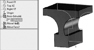
You may be able to imagine that in a part with a much longer feature tree, where the relationships between the faces and the features are more complex, overriding that complexity by editing a face directly could have some appeal.
SolidWorks has several features that do not create new geometry, but edit existing geometry only, whether it is native or imported. These include the following:
Move Face
Delete Face
Freeform
Flex
Deform
Scale
I'll show you a slightly more complex example. In traditional SolidWorks usage, if you wanted to move the face indicated in Figure 30.16, you would go back and edit the sketch or feature that was used to create it. That would be easy enough, and the fillets would update to match the new geometry.
The direct edit salesmen would say that first finding the feature you need to change is difficult, then waiting for the change to rebuild all the features, and last dealing with the downstream features like fillets that might fail due to the changes is frustrating, and he would be right. The problem is that the part, as shown in Figure 30.16, cannot be changed at all in direct edit software. In the direct edit scheme, the fillets are just faces; they are not intelligent features. If you move faces they are attached, you have to also explicitly tell the fillet faces what to do as well.
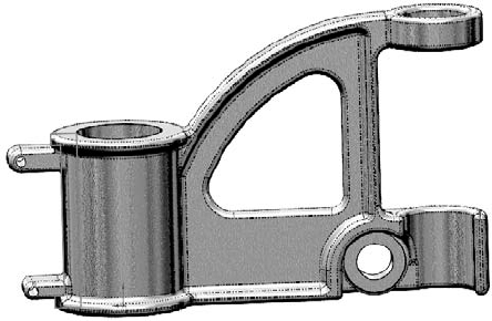
Here's how to simplify the part by suppressing fillets and using the Move Face feature to change the part (see Figure 30.17). Here, I've moved the ring around the top of the barrel as well as the mounting boss. In order to make this move, I had to select seven faces:
Top of ring
Bottom of ring on left
Bottom of ring on right
Top of boss
Bottom of boss
Full round on end of boss
Hole in the mounting boss
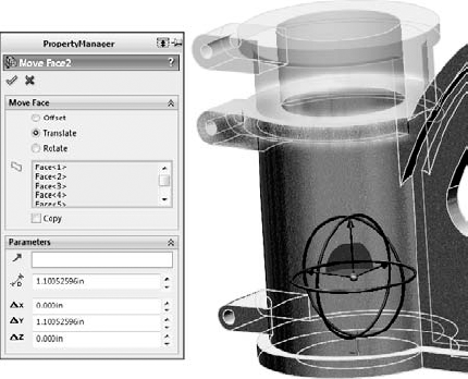
Figure 30.17. Using Move Face to extend the length of the barrel of the cast part after the fillets have been removed
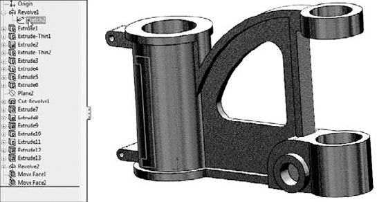
Notice how the Web now extends up the side of the barrel. This is the type of edit that would be clumsy in SolidWorks if it were what you wanted to do. In direct edit, it is the kind of edit that would be clumsy if it were not what you wanted to do.
This is one of the limitations of direct edit techniques in general — not a limitation of SolidWorks, but a limitation of the concept. Direct edit cannot make new faces without adding another feature, and has problems with the intelligent type of face creation that you find in history-based systems. Direct edit programs are certainly not more powerful than SolidWorks or any other history-based CAD program. They have weaknesses in different areas, and the weaknesses are more limiting than SolidWorks history-based weaknesses.
Figure 30.18 shows where the weakness of using the direct edit tools within SolidWorks begins to show up. The first feature in the part is a revolve that uses a sketch. The last feature in the part is a Move Face feature that moves the faces created by the revolve. So if you want to change the geometry of the barrel, it is controlled by two different features. If you make the sketch a specific size, the Move Face feature will change it. Move Face can only change relative to a starting point; it cannot make something a specific dimension.
Some SolidWorks power users consider this double-jeopardy condition sloppy design or bad practice. You can make a strong case that the direct edit tools should not be used on native SolidWorks parts, and that you should edit the feature the way it was created. There is certainly a place for that argument. But I know from my own modeling work that sometimes changing a feature way back in the tree can have unintended repercussions later in the tree, so using a Move Face feature late in the tree avoids fixing a lot of propagated errors. Is that a cheap, sleazy cheat? You will have to decide that for yourself.
Regardless of any argument against using direct edit tools on native SolidWorks data, there can be no such argument against using them on imported data. Direct edit tools may have their limitations, but when dealing with imported geometry in SolidWorks, your choices are limited as you see from the following:
When faced with these options, direct edit tools look like the safe choice. The big problem will be that if the part is covered with fillets, you may not be able to change much. In cases like that, you might use a combination of tools, such as FeatureWorks to remove fillets, and then direct edit to make changes.
FeatureWorks works by deconstructing, or "unbuilding," the part, removing faces of features that would be applied last. For example, first it will try to recognize fillets, and removes them from the model. Then it recognizes other types of features, including holes, and then finally it recognizes the base extrude or revolve feature.
You can use this as part of your process, but only deconstructing the part partially, leaving the portion of the part that is not assigned to a feature as an imported body. If you remove the fillets and the holes, you might be able to do the edits that remain using direct edit tools. This will leave you with a partially imported part with some parametric features and some direct edit features. Some folks might consider this a sloppy mess, but getting work done on schedule does count for something; if that is what it takes, then it removes the sting to some extent. The FeatureWorks PropertyManager is shown in Figure 30.19.

This tutorial walks you through the button-clicks to import CAD data from IGES and make some edits.
From the CD-ROM, open the file called
cover.igs. You can open this file by selecting it in the Open dialog box (File
Right-click -the Imported1 feature and run the Import Diagnosis. Notice that Import Diagnosis finds no errors on the part.
Look at the inside of the part, in the area near the part origin. Notice on one end of the tab, all the fillets come to a point, as shown in Figure 30.20. This is clearly not right, although Import Diagnosis did not identify it as a problem.


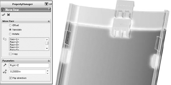
This tutorial steps you through importing and editing geometry using the Move Face, Flex, and Freeform features in SolidWorks.


Select the body in the graphics window in the top selection box.
Select Bending option in the Flex Input section.
Select Hard edges in the Flex Input section.
Select 190deg for the angle.
In Trim Plane 1, set the distance to 1.9 inch.
In Trim Plane 2, set the distance to 4.5 inches.
Accept the feature when you are done.


Note
The Split Line will split the outside and the inside of the curved face. If you select Shaded With Edges, you will be able to see the split on both sides.

Click the Direction 1 Symmetry option, and a gray plane should appear along the Right (YZ) plane.
Click the Add Curves button, and then snap the cursor to the symmetry plane and click to add a curve. The symmetry plane will highlight orange when it is selected. Add a second curve parallel to the first one about one-third of the way from the symmetry plane to the edge of the split.
Click the Add Points button, and place a point approximately, as shown in Figure 30.24.
Place a point on the second curve in approximately the same location as the first point. Figure 30.24 shows one point on each curve.
Click the Add Points button to deselect it when you are done.
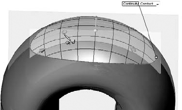
Change the Continuity flag pointing to the edge of the split from Contact to Curvature.
Click on the curve on the symmetry plane, then click on the point on that curve. Drag the arrow handle to pull the point away from the part approximately, as shown in Figure 30.25.
Click on the second curve, and then click and move the second point in a way similar to the first point. When you are done, the part should look similar to Figure 30.26.
Save the file as a different name.


In recent years direct edit tools have received a lot of hyped press and marketing attention. However, CAD tools dedicated to working primarily as direct edit tools are not going to overtake the tools used by professionals who design and model for production. If anything, they will be used primarily by non-CAD specialists for simple editing and simple concept development, and possibly by downstream data consumers like FEA analysts or CNC (Computer Numerical Control) machinists.
The direct edit tools available within SolidWorks are powerful, and are becoming more powerful with each release. While they might be best applied to imported data, they can also be applied to native SolidWorks data. This brings up questions of best practice and duplication of effort. Sometimes the changes involved in editing a feature that is near the top of a long feature tree can be time-consuming compared to simply moving a couple of faces.