
The Hole Wizard and Toolbox are two applications that go together because they both work from a single database of matching hole and fastener sizes. One of the most useful examples of combining these two applications is the capability to automatically place holes through multiple parts and put appropriately sized screws and hardware into the holes, all in one step. The hole knows which fastener, or stack of fasteners, needs to go together.
Many automatic aspects of Toolbox exist, and the concept behind the combination of Toolbox and the Hole Wizard is compelling due to the level of shared information and automation. This chapter aims to give you the information you need to decide how to implement and use Toolbox in your work.
Pre-select the face to put the holes on, although this is not required. SolidWorks 2010 no longer requires pre-selection to avoid 3D placement sketches; the Hole Wizard now used 2D sketches by default.
Select the type of hole; for example, counterbored, countersunk, drilled hole, tapped hole, pipe tap, or legacy.
Set the standard to be used, such as ANSI (American National Standards Institute) inch, ANSI metric, or ISO (International Organization for Standardization).
Select the type of screw. For example, a counterbored hole can accommodate a socket head cap screw or a hex head screw, among others.
Select the size of the screw.
Select the fit of the screw into the hole, such as normal, loose, or close.
Select the end condition of the hole.
Select options for clearance and countersinks or edge breaks.
Alternatively, you can use or assign a favorite. A favorite is a hole with settings that you use frequently and want to save. I discuss these later in this chapter.
You can use Custom Sizing when you need a hole with non-standard dimensions.
Locate the center of the hole or holes. You can place multiple holes in a single Hole Wizard feature, even on different faces and curved faces. I address the specifics of this step later in this chapter.
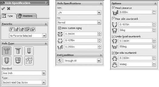
Click OK to accept the type, size, and placement of the hole. Figure 17.1 shows the Hole Wizard PropertyManager interface.
Hole Wizard holes are made of two sketches: a center placement sketch and a revolved cut profile. Figure 17.2 shows a simple part with an expanded Hole Wizard feature. Notice that the feature is named for the size and type of the hole.
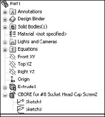
The placement sketch is listed first under the Hole Wizard feature. It contains one or more sketch points marking the hole centers. It may also contain construction geometry with relations and dimensions to parametrically locate the hole centers. I discuss placement sketches in more detail in the next section.
The revolve profile sketch is not on an identifiable sketch plane that you can reuse for other features, although that would be useful. You can change the sketch dimensions outside of the wizard interface, and if you later use the wizard to edit it, then the changes appear in the Custom Sizing panel. Figure 17.3 shows the Custom Sizing panel with the changed counterbore diameter highlighted.

If you select any of the choices from the Options panel, the revolved sketch profile is altered to accommodate the change. For example, if you select the check box for a near side countersink, the sketch changes to add a line for the countersink; a separate chamfer feature is not added.
In SolidWorks 2010, SolidWorks changed the Hole Wizard so that it defaults to a 2D sketch. Pre-selection of a plane or planar face is still recommended because it eliminates a step later on, but it is no longer required in order to avoid being forced into a 3D placement sketch. 3D placement sketches are still available and still useful, but because they are so much more difficult to use and rarely truly needed, SolidWorks decided to change the default to a 2D sketch.
3D placement sketches are needed for Hole Wizard holes if you have a set of similar holes that are placed on different levels or are always perpendicular to non-planar surfaces. If you need 3D placement sketches, they are still available, but they are no longer the default.
For most people who have learned to pre-select a face before opening the Hole Wizard, this change will have no effect. It will have a positive effect on new users and those who frequently forget to pre-select.
The main advantages of the 2D sketch method are the simplicity and completeness of the available tools. Everyone knows how to manage 2D sketches, sketch planes, dimensions, and construction geometry.
A limitation of the 2D sketch is that the holes that you create through this method are limited to a single planar face, and the holes will all be perpendicular to that face. Sometimes this creates a great limitation, while other times it does not matter.
The obvious advantage of the 3D placement sketch is that it can put a set of holes on any set of solid faces, regardless of whether they are at different levels, are non-parallel, or are even non-planar. This function offers multiple holes, multiple faces, and multiple directions. In situations where that is what you need, nothing else will do.
A limitation of the 3D sketch is that it can be fairly cumbersome. Dimensions work very differently in 3D sketches compared to 2D sketches. For example, to create and place a hole in a specific position on a cylinder, you need to follow these steps:
Begin with a circle with a diameter of one inch, drawn on the Top plane and extruded using the Mid-plane option one inch.
Start the Hole Wizard without any pre-selection, either through the Features toolbar or by choosing Insert
Features HoleWizard.
Set the interface to use an ANSI inch, one-quarter-inch, and counterbored hole for a socket head cap screw. Use a Normal fit and Through All for the End Condition, with a .100-inch head clearance (in the Options panel) and no custom sizing changes. These settings are shown in Figure 17.4.
Click the Positions tab, which is located at the top of the PropertyManager window. The interface asks you to select a face where you would like to put the holes or to select the 3D sketch option. In this case, click the 3D Sketch button.
Note
Be careful with clicking when the Point tool is turned on. For example, if you click in a blank space, the Point tool places a point off the part. SolidWorks will try to use the point later to create a hole in empty space, which usually causes an error.

Click the cylindrical surface of the part. The surface appears orange when you move the cursor over it to indicate that an OnSurface sketch relation will be created between the sketch point and the cylindrical surface.
The hole should be positioned from one end of the cylinder. Using the SmartDimension tool, click one flat end face of the cylinder and the sketch point. Place the dimension and give it a value of .300 inches, as shown in Figure 17.5.
Locating the point angularly around the cylinder is more difficult. You can use several methods to do this, but this example shows one using construction sketch geometry.
Tip
To force a 3D dimension to have a certain orientation, dimension from a plane or planar face rather than from an edge, vertex, or sketch entity. A dimension from a plane is always measured in a direction perpendicular to the plane, but a dimension from a line or point is always measured by the shortest distance between the entities. Two-dimensional sketches can force dimensions to be horizontal or vertical, but 3D sketches cannot.
With the Line tool activated while still in the 3D sketch, Ctrl+click the flat end face that the previous dimension referenced. This moves the red "space handle" origin to the selected face and constrains any new sketch entities to that face. You are still in the 3D sketch, but are constrained to the selected plane and still must play by all the 3D sketch rules. The elements of 3D sketches are described in detail in Chapter 31.
Select the Temporary Axes view by choosing View
Temporary Axes.Place the cursor near the center of the activated end face; a small, black circle appears, indicating that the end point of the line will pick up a coincident relation to the temporary axis. Draw the line so that it picks up an AlongX sketch relation. The cursor shows the relations about to be applied, just like in a 2D sketch.
Draw a second line again from the center, but this time do not pick up any automatic relations. This line should also be on the flat end face.

Note
Although you can set these lines to display as construction lines if you like, this is not required for the feature to work; the lines also work as regular solid lines.
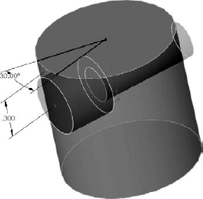
Put an angle dimension between the lines and change the angle to 30 degrees. To be thorough (which is always recommended in 3D sketches, which have a tendency to handle underconstrained sketch geometry unpredictably), constrain the ends of the lines to the circular edge of the cylinder. At this point, the part looks like Figure 17.6.
Create an AlongY sketch relation between the points indicated in Figure 17.7. The hole centerpoint on the cylindrical face is one of the points, as well as the endpoint of the angled line. Change the angle dimension to ensure that it is controlling the sketch point as expected. Click the green check in the upper-right corner of the graphics window to accept the result and exit the command.

On the CD-ROM
You can find the finished part from this example on the CD-ROM named Chapter 17 3D Hole Placement.sldprt.
Hole Wizard Favorites store types of holes that you use frequently so that you can simply recall a favorite, rather than manually making all the changes every time you use the same hole. Favorites are saved to a database named Default.mdb as you create them, and are immediately available from all other part documents. You can also save favorites to a special file type with the extension *.sldhwfvt. Other users can then load these files and add your favorites to their Default.mdb databases. This is a convenient way to create company standards for hole features.
Shared Toolbox installations share a SWBrowser.mdb between several users, making Hole Wizard Favorites available to everyone. I cover how to set up shared Toolbox installations later in this chapter.
To create a Hole Wizard Favorite, set up a Hole Wizard hole as you normally would, and then use the Add Favorite button to add it to the Favorites database. The Hole Wizard Favorite panel contains five buttons:
You can use Hole Wizard Favorites to store custom holes. Create the hole with its custom sizes, and then add the favorite and give it a recognizable name. The custom hole will now be available to anyone who connects to the same database file.
The database file is typically found in the Data subdirectory of the SolidWorks installation directory, but an option in Tools
Further, the *.sldhwfvt files do not have an entry in the File Locations list, but seem to always default to the langenglish subdirectory of the SolidWorks installation directory. Neither this location nor the Data directory makes sharing among multiple users very convenient, but both file types can be copied to other installations. You may want to read through Chapter 18 to learn about setting up libraries for all file types.
Best Practice
It is a best practice to create a folder for library type files that you want to save and use with a future version of SolidWorks. You can specify the locations for these files by choosing Tools
Hole Wizard Favorites seem to have a couple of quirks that are possibly "sub-optimal," as they say. First, you can only see the favorites for a specific type of hole when that type of hole is activated in the interface. For example, if you have a number of favorites for countersunk holes, but you currently have the counterbored hole icon activated, you will not be able to see the countersunk favorites until you switch to the countersunk icon.
If you have a lot of favorites, this may be beneficial, but if you have only a few favorites, or you do not use favorites frequently, it may be confusing and can create some unnecessary steps to find all your favorites.
A second quirk occurs when you allow SolidWorks to name the favorites and you have fractional values such as ¼ — which happens now and then in hole sizes — and then try to save the favorites. Each favorite is saved as a separate file, using the name that was automatically assigned to it by SolidWorks as the filename. Unfortunately, the character "/" is not allowed in a filename, so it fails.
The Hole Series used to be part of the Hole Wizard, but has since been exported as a separate tool. It is now a five-step, wizard-based feature, ending with populating the new hole with a fastener using Smart Fasteners functionality. The Toolbox add-in is required to use Smart Fasteners. Figure 17.8 shows the interface for the various steps.
When using the Hole Series feature, you must follow these basic steps:
Have an assembly open with two or more parts in it that need to be fastened together.
Initiate the Hole Series tool by choosing Insert
Assembly FeaturesHoleHole Series. It is also available as a toolbar button, but it is not on the toolbar by default.If the Hole Series is to be started from an existing hole, then select it in the Hole Position panel. If not, then use sketch points, construction geometry, dimensions, and sketch relations to locate the hole centerpoints.
Use the tabs at the top of the PropertyManager to advance from one panel to the next.
The Start Hole Specification refers to the part where the series of holes starts.
The Middle Hole Specification is for all parts between the first part and the last part.
The End Hole Specification is the last part and is either a through clearance hole or a threaded hole.

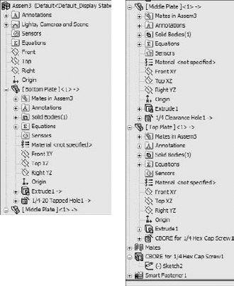
The finished feature leaves an in-context feature in each part, with the Hole Series part in the assembly, as shown in Figure 17.9.
The Hole Series feature also has some quirks that you should know about so you don't spend too much time trying to verify that things are not working as you would expect. The first is that if you start the Hole Series without preselection, the cursor that comes up initially is a 3D sketch cursor, but once you click the cursor to place a point on a face, the Hole Series tool creates a 2D sketch feature.
The second example is actually from a tutorial in Chapter 16, and is where the Hole Series drills multiple holes and the holes will not all go through the same parts. This is like the example shown in Figure 17.10, where a hole drilled down from the top of plate 1 might drill into plate 5 or plate 6. In this case, you would have to create holes that drill into different parts separately, as was done in Chapter 16.
Also, you may find that the Hole Series does not retain the information you give it for "End Part," or the depth of the tapped hole at the end of the series. Behavior like this makes the Hole Series difficult to use reliably, so make sure to double-check any data created with the Hole Series feature. It is a highly convenient feature, but may also be flawed.

If you are an individual user who is using Toolbox on your own and not sharing data with others, the default Toolbox settings should be fine. But if you are one among a large group of users, a dedicated implementation effort is needed.
This book primarily covers Toolbox for the end user perspective. If you are looking for information from the administrative perspective, I recommend the SolidWorks Administration Bible (Wiley, 2009). That book covers various schemes for implementing Toolbox.
Warning
Improper installation, maintenance, or management of Toolbox can cause the loss of all useful information about fasteners and hardware in your assemblies.
Toolbox creates fasteners and other hardware components on the fly or reuses existing parts when possible. Technically, it is not a library, but a configurator. Libraries store existing components, while configurators build them on the fly from information supplied by the user.
One advantage of configurators is that the parts start out very compact because there is only the default size, and the sizes are efficiently stored in a database and created as needed.
The advantage of a library is that it enables you to simply plug in the parts to make them work. All Toolbox really needs to do for users is provide a library of parts. Anything more than that is only beneficial if it offers some improvement over a simple library of existing parts without introducing any risks or setbacks.
No one asks how a staircase works, because it does not work; it simply exists and people use it. An escalator, however, is a different issue. With an escalator, there is a complex installation, and then to use it, you have to know how to get on and get off and what to do if it stops working. The end results of using the staircase and using the escalator are the same (you start at the bottom and arrive at the top), but the complex automation is supposed to save you some effort.
That is one way you can look at Toolbox. The end product is supposed to be the same as using a static library of parts, but there is some mechanism behind the scenes that has to be set up and maintained properly in order for it to work in the way you expect. Most SolidWorks books, tutorials, or training materials are going to ask you to accept what happens inside Toolbox as a "black box" and to just assume that the end results are exactly what you need and intend. Here, I supply you with information about how it works, so you can decide how useful it will be for you.
Toolbox has three major components:
Default parts of one size, with named dimensions and features
A database containing all size information for all parts and Hole Wizard holes
A software application with settings and an interface
When Toolbox is installed, it starts as a set of SolidWorks parts with named features and dimensions, some suppressed features (depending on settings), some dlls (executable programs), and a database. The parts have a single Default configuration, which is typically one of the size extremities, either the largest or smallest. The database starts out about 87MB and includes all the size information for all the parts, as well as all the standards information.
If you create a custom standard in Toolbox, it actually replicates a section of the database. By doing this, the database file can easily double in size.
Later, you will see that a network installation of Toolbox requires the database to be on the network, and every time you create a new fastener, it has to open the database. As a result, simply placing a screw in an assembly can mean that even if your assembly is located on your local hard drive, you still have to open a very large database file across the network. The first rule about performance with SolidWorks is to work locally rather than across a network.
By default, the database is located at C:Solidworks DatalangEnglish. You can open this file with Microsoft Access or Excel.
Note
When specifying network paths, it is best to specify a Universal Naming Convention, or UNC, path rather than a mapped address. A UNC address follows the format, \ServerShared Folder. The advantage of the UNC over the mapped drive is that mapped drives can vary from one computer to another, but the UNC is always the same.
If you have just installed Toolbox the way that most, if not all, new users do, then you will accept all defaults and trust the software that you just purchased to not give you bad advice. In this situation, the database is installed locally and Toolbox is set to use configurations for sizes.
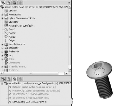
When you put a Toolbox part into an assembly, you do not even notice anything other than the part going into the assembly, although it may hesitate while the large database is opened. If you check the part configurations, you may notice that there is a Default config and a new config that represents the size that you just created. Every new size that you create makes another new configuration. Figure 17.11 shows a Toolbox part with the FeatureManager and ConfigurationManager open, showing several configurations that Toolbox created in this particular fastener.
Next, you may receive an assembly from a client. Often, because Toolbox parts are located in an area where you would not necessarily look for parts, users send assemblies and parts, but do not send Toolbox parts. You may think that this is okay; after all, you have Toolbox on your system; therefore, it should pick up your toolbox parts. The truth is that when receiving an assembly from someone else, you are better off if one of the parties does not have Toolbox on their system.
If both you and the client who sent the assembly have Toolbox, then you should be okay, right? Well, yes and no. Yes, your client's assembly will pick up your Toolbox parts, but no, it will not work properly because you do not have all the same configurations and sizes that your client has. In cases like this, you will experience what I have come to refer to as the Huge Screws syndrome. When SolidWorks finds the right file but cannot find the right configuration, it uses another configuration, usually the Default, which is generally the biggest size. This is where the Huge Screws name came from.
Part of the really bad news is that if you save your assembly with the Huge Screws, SolidWorks has no way of knowing that the huge screws are not the correct screws, and you can only solve the problem manually by going through the assembly and reassigning sizes to the huge screws.
You can work around this by opening an assembly that has not yet been saved with the Huge Screws, using the Advanced option in the Open dialog box (you can find this in the Configurations list), and then selecting the New configuration showing assembly structure only option. With this option, all components are suppressed. You can unsuppress any non-Toolbox parts and continue working. Ask your client to send you his Toolbox parts and then unsuppress those parts in the assembly, making sure that it finds the right parts; this is best done by having the correct parts already open before you open the assembly. These options are shown in Figure 17.12.
If you replace your Toolbox parts with the Toolbox parts from the client, you may experience the same problem in reverse if you had configs that your client did not. In the end, it would be great to be able to merge the two parts to combine all the available sizes into a single file. There is a way of doing that, which I will describe later, but it is a convoluted work-around. Files that have the same names and different content are at the top of the list of things you shouldn't do in file management, and yet the SolidWorks Toolbox system frequently creates this very situation.
To be fair, SolidWorks fixed the Huge Screws problem in the 2007 version by coming up with a clever method for figuring out which size is missing and building it on the fly when the assembly is opened. Additional information about the Toolbox parts is now stored in the assembly, which helps identify the missing parts. Unfortunately, the fix only works for assemblies that use the parts from the 2007 or later library and assemblies that have been built in SolidWorks 2007 or later. To sum up, if you have assemblies built in an older version of SolidWorks and your Toolbox library becomes corrupted or lost or you are sent an assembly that uses a different Toolbox library, even if you are working in a version later than SolidWorks 2007, you cannot benefit from this fix.

This is disappointing in many respects because if you have existing Huge Screws problems, you will continue to have them until you rebuild the assembly or manually repair the configurations. It is doubly disappointing because the information needed to re-create the correct configuration has always been stored in the assembly — the filename and the configuration name are enough — but SolidWorks has missed an opportunity to really fix this problem.
I provide some recommendations before the tutorial at the end of this chapter if you are still interested in using Toolbox.
Toolbox parts can be organized in a number of ways. The raw parts are organized as follows:
Standard and Units (for example, ANSI Inch or ANSI Metric; most standards do not include multiple units, they assume metric).
Hardware Type (such as bearings, bolts, and bushings).
Each type is organized differently, but bolts and screws are organized by drive or head type. (For example, you have socket head screws, hex head, and thumb screws.)
Filenames look like
Socket Button Head Cap Screw_AI.SLDPRT, where theAIrepresents ANSI Inch.
Figure 17.13 shows this organization in part.
By now you might be unsure about using configurations in general. If so, that is not the message I am trying to convey. Configurations in themselves are not the problem; the problem here is in the file management practice of having files with the same names but different content. Mixing that with the practice of trying to treat "configurator" software like a "library" exacerbates the problem.
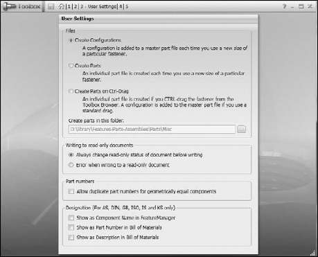
That said, you have two options regarding how you create different sizes. The default option is that sizes are created as configurations within a single part. The other option is that sizes are created as individual files.
The best time to make this choice is before you install SolidWorks. Unfortunately, before you install SolidWorks, you probably do not have any idea that these issues exist. The reason for making this decision not just early, but immediately, is that if you start using the default setting (configurations), and make a few configurations for some parts and then switch to using the Save Parts setting, the parts that are saved out will all have the pre-existing configurations and thus different sizes.
If you find yourself in this situation, it is better to reinstall Toolbox or simply to copy over a new default set of parts with no configurations.
You can access the Create Configurations and Create Parts options by choosing Toolbox
The following list contains some pros and cons for each option.
Configurations are better for:
Controlling data across several sizes. For example, a design table can drive custom properties that are added to all configurations. Doing this with many individual parts would be very messy.
The interface to select configurations from a list is easier to work with than the interface to select a part from a list.
File management organization is somewhat easier for configured parts.
Separate parts are better for:
Keeping the file size small.
Replacing all of one size part with another.
Guaranteeing that you will never have the Huge Screws problem.
Toolbox has two components: Toolbox and Toolbox Browser. In practice, the Toolbox component is often ignored, and the Toolbox Browser component is generally referred to as Toolbox.
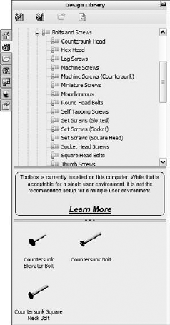
The Toolbox Browser is the Task Pane interface and is found on the Design Library tab, as shown in Figure 17.15. The Toolbox component is found in the Toolbox drop-down menu. It includes structural steel shapes, grooves, cams, and beam and bearing calculators.

You can turn on Toolbox and the Toolbox Browser through the Tools

Once the Toolbox Browser is turned on, you can use it by expanding the Task Pane at the right of the SolidWorks graphics window and clicking the Design Library, which looks like a stack of books. In this panel, you will see the Toolbox screw symbol. Expand icons until you find the fastener or other hardware that you are looking for, and then drag the part into the assembly.
Holes can be populated in several ways, such as dragging-and-dropping, populating multiple holes at once, using the right mouse button (RMB) menu, and using feature-driven component patterns. I discuss manual and patterning options here, and Smart Fasteners in the next section.
The simplest way to bring Toolbox parts into an assembly is to drag-and-drop them. Position the part that the fastener goes into so that you can see the edge of the hole where the screw head will go. Then browse to the correct fastener and drop the fastener onto the edge, as shown in Figure 17.17.

Toolbox parts will even automatically size themselves based on the hole. It is best to use Hole Wizard holes if you are going to use this function of Toolbox parts. Hole Wizard and Toolbox are meant to work together.
When you place the fastener, a PropertyManager appears that enables you to select various properties of the part, including the length, if you want to override the automatically selected size, the thread representation, and if you want the fastener to change in size when the hole changes. Also after placing the fastener, a handle at the end of it enables you to drag the length of the fastener, which will snap to predetermined lengths. You can also drag the arrow that appears at the end of the fastener to graphically select the length.
Figure 17.18 shows the progression from a plate with holes in an assembly. In this example, you would Ctrl+select the edges of the holes, then select a fastener, and then choose Insert Into Assembly from the RMB menu to populate multiple holes.

Chapter 15 covers Feature Driven component patterns (also known as derived patterns), where a pattern of parts in an assembly is driven by a feature pattern in a part. You can find this assembly feature by choosing Insert
One way to use Smart Fasteners is in conjunction with Hole Wizard Hole Series. Hole Series creates the holes through multiple parts at once, creating the appropriate type of hole through each part, and then Smart Fasteners automatically places fasteners in the holes, even including nuts and washers. To do this, you can select the option on the last panel of the Hole Series PropertyManager interface, as shown in Figure 17.19. If you are planning on using Smart Fasteners, using them in conjunction with the Hole Series holes is your best bet.

The Smart Fasteners with Hole Series is a function that you should be careful with. It is very effective, but it may cost you some performance (speed). The Hole Series is an assembly feature that drives several in-context features, and then parts are mated to those in-context features (fasteners).
Smart Fasteners functionality has an even more automatic component. Once an assembly has parts mated into place, you can place fasteners into parts with appropriate holes by face, by part, or for the entire assembly at once.
Warning
You may not want to spend a lot of time trying to use this type of the Smart Fasteners functionality. I have tried to find examples where Smart Fasteners works well and predictably, but with limited success. I have searched through training examples, through tutorial files from SolidWorks, and have even made some of my own example files. I have looked for presentations from user groups and SolidWorks World that use Smart Fasteners, but no one appears to be talking about this functionality. Although in theory, it offers interesting functionality, in reality, it receives very little attention — definitely a warning sign.
The one assembly that I did find where Smart Fasteners worked surprisingly well (in fact, almost perfectly) was from the sample files that installed with SolidWorks. Upon closer examination, the reason this worked well was because it used assembly features for the holes, and so the holes did not appear in the individual parts. If that is the price that you have to pay just to get fasteners to populate automatically, then you will probably rather put them all in manually.
Smart Fasteners have some documented limitations where you should not expect them to work:
Holes in single parts
Holes created by extruding a nested loop
A mirrored hole or cut features
Holes in mirrored, imported, or derived parts
Misaligned holes
Holes with a large difference in diameter
Holes with large gaps between them (a large gap in the axial direction)
Holes made using different techniques (such as sketch pattern versus feature pattern)
If you would like to try out Smart Fasteners, then you can use the assembly included on the CD-ROM called Chapter 17 Smart Fasteners.sldasm. In this assembly, half of the holes are done correctly and the other half are not: the screws are put in either backward or headfirst. The documented method for flipping the fasteners is to expand the Smart Fastener, right-click the series, and choose Flip. In this case, my attempts resulted in success about half of time, which was somewhat higher than my attempts with other assemblies. In some cases, screws were put in the ends of shafts without holes, on filleted edges, and unfortunately missed most of the places that I did want the screws to go.
Assembly FeatureManagers are hard enough to manage when they become full of parts; they become even more unmanageable when they also need to include the many types of fastener parts. As a result, I recommend organizing fasteners, as well as any other type of part that is found in large quantity in the assembly, into folders, as shown in Figure 17.20. You should also group parts of the same size or function together.
After spending almost an entire chapter saying what you should not do, it is finally time to say what you should do. Toolbox can be downright dangerous if you install and use it improperly; however, the following recommendations work in most situations.
Just to be clear about this, the most serious file management problems with Toolbox show up when you use configurations, which just happens to be the default option. Still, I'm a big fan of using configurations in general, and especially with library parts, but a Toolbox implementation with configurations is challenging. Again, this is because of the file management issue of different users having the same part names with different content (Toolbox parts with or without certain configurations created).

If you are a single user who does not share files over a network with other users, then installing SolidWorks and Toolbox with the default settings should work for you. This appears to be the arrangement that the developers had in mind when they programmed the tool, because it is the only scenario in which it works as expected.
Be careful if you ever receive an assembly from another Toolbox user, because this is the one situation that can cause immediate trouble. If the user also sends his Toolbox parts, then I recommend that you open all his Toolbox parts before you open his assembly so that the assembly is certain to access his Toolbox parts instead of yours.
If you need to include materials and mass-populate custom properties, then I recommend that you go through the exercise of building all the configurations of all the parts, and then use an auto-created design table to drive the properties. If you have more than one user, then this technique will not work for you, unless both users work independently from one another.
If you have multiple users that share assemblies, then you need to also share the Toolbox library. If you share assemblies only among yourselves, meaning only with other users who are also sharing Toolbox, then sharing Toolbox should be good enough. However, if you share assemblies with Toolbox users who do not share your Toolbox library, then you should probably go through the exercise of populating all your parts with all the available configurations. If you do not receive assemblies from outside of your group with Toolbox parts in the assembly and you have network performance problems, it may be a good idea to install Toolbox locally, but to set it to use the Create Parts setting, where the parts are on a shared network location.
If you use a Product Data Management (PDM) system, then I would definitely install Toolbox locally and use the Create Parts setting. The sharing occurs through the PDM system. Library parts should be non-revision managed parts, but you may want to have a representation of the fasteners so you can do where-used searches and BOMs.
The least problematic technique is to turn Toolbox off altogether and either buy or make your own library of static parts. You can then distribute these files internally in your organization, as well as to any other people upstream or downstream from you who also share files with you. You can build this type of library by using Toolbox's config population tool; materials or other custom properties are then dealt with the way you want, likely using auto-created design tables.
Of course, there is a downside to this too, and it is that you lose all the nice automation features available with Toolbox. The best option if you want to keep Toolbox is to use the Copy Parts option, install locally, use a PDM system, and if you get assemblies from Toolbox users who aren't part of your network, insist that they either use your parts or send you their parts.
For a more complete discussion of the administration issues surrounding SolidWorks Toolbox, please refer to the SolidWorks Administration Bible (Wiley, 2009).
Figure 17.21 shows a section view of the assembly used for this tutorial. Notice that there is a gasket under the Sensor part.
This tutorial assumes that you have a working copy of Toolbox running on your computer. If you do not have Toolbox, then you can proceed to the next chapter. This tutorial also assumes that your Toolbox is using the default Create Configurations setting, although it can also work with the Create Parts setting. To get some experience using this tool, follow these steps:

Open the assembly from the CD-ROM called Chapter 17
Tutorialstart.sldasm.Make sure that the Toolbox Browser is turned on by choosing Tools
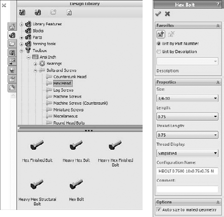
Expand the Task pane, found on the right side of the graphics window, and display the Design Library panel, which contains the Toolbox icon. Expand the ANSI Inch standard, and the Bolts and Screws folder, and finally click the Hex Head bolt, as shown on the left in Figure 17.22. Drag-and-drop the Hex bolt into any hole. It snaps into place because of the Mate Reference that is used on the Toolbox part. Toolbox should automatically size the bolt correctly. Click the green check when you are done, then click the red X to finish placing bolts.
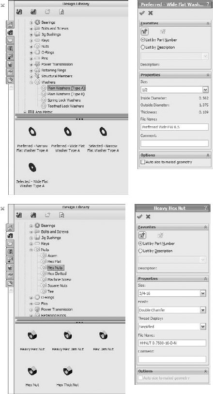
Add a flat washer and nut to the bolt, as shown in Figure 17.23. The washer is Plain Washer Type A, Preferred - Wide Flat Washer. The nut used is Hex Nut, Heavy Hex Nut.
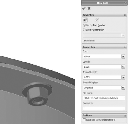
Right-click the bolt, either in the graphics window or in the FeatureManager, and select Edit Toolbox Definition, toward the bottom of the menu. Notice that the bolt is too short, as shown in Figure 17.24. Change the length of the fastener to 1.625 inches. You can change this in the PropertyManager or by dragging the green arrow placed on the bolt.
Note
If you try to apply Smart Fasteners to the hole, you will notice that the fastener is placed incorrectly, and changing fastener types is not simple.
Create a Feature Driven component pattern (Insert
Component PatternFeature Driven) using the circular pattern of holes on either the Top or Base parts. Pattern the bolt, washer, and nut all in the same component pattern.Zoom in on the sensor on the top of the assembly. There is a gray gasket between the orange sensor and the blue top parts. Click one of the flat ends of the sensor part and then click the Hole Series toolbar button, or choose Insert
Make sure that you select the Place Fastener option on the final tab when you get there, as well as the Create New Hole option. This workflow is different from previous versions. Be aware also that Toolbox may delay several seconds as you initiate these features.
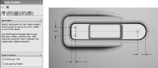
Make three sketch points and use construction geometry and dimensions to locate the holes, as shown in Figure 17.25. The size and types of holes are determined in a later step. (This is the reverse of the normal Hole Wizard, where you first determine the type and size of hole, and then you establish the positions.)
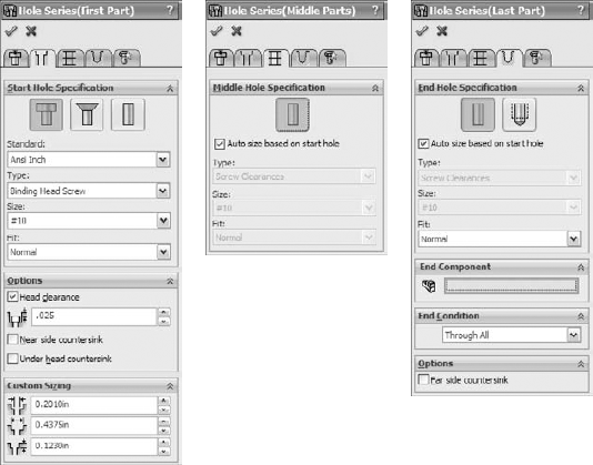
Click the Next button (the blue arrow pointing right) to move to the First Part hole specification. Set it to a counterbored hole, for a #10 binding head screw, with a head clearance of .025 inches, as shown in Figure 17.26 in the image to the left. Click the Next button to advance to the Middle Parts hole sizing.
In the Middle Parts PropertyManager, make sure that the Auto size based on start hole option is selected, as shown the middle image in Figure 17.26. This creates a normal fit clearance hole for the gasket part. Click Next to advance to the hole definition for the Last Part.
In the End Hole Specification panel, make sure that you select the Hole rather than the Tap option, as well as the Auto size based on start hole option. This is shown to the right in Figure 17.27.
Proceed to the Smart Fasteners tab. Make sure the Place Fastener option is selected, along with the Auto size option.
Add a washer and a nut to the bottom stack of the binding head screws. Using the Stack Components panel of the final tab of the Hole Series/Smart Fastener interface, add a washer and a nut to the bottom stack.
A dialog box appears, enabling you to add a washer and a nut, as shown in Figure 17.28. You may want to roll the model over so that you can see the components being added to the underside of the screw. You can add other properties to the parts by clicking the Properties button. Notice that the screw has been lengthened to accommodate the added components.
Note
If you add a washer to the top stack, the hole does not automatically become larger, and it may cause interference. Be careful about your choice of top-stack washers.
Note
You may have noticed that this time, Smart Fasteners worked almost flawlessly and certainly saved you some time. Although this tool is not applicable to other purposes, when used with the Hole Series, it is quite useful.
Warning
The final version of the assembly on the CD-ROM may open up on your computer with Huge Screws if you open it before completing the tutorial. This is because the configurations used in the assembly are on my computer. Although you have the same parts, before doing this tutorial, you may not have the same configurations; therefore, they cannot be found and come in Huge instead. This was intentional; it is a practical reminder of this problem and how easily it can happen to you.
You may want to group the fasteners and even the fasteners' mates into folders, as shown in Figure 17.29.


The Hole Wizard can make holes based on 2D or 3D sketches. The type of hole that you create is up to you. Two-dimensional sketches are far easier to use than 3D sketches.
I have met people who claim to have had good success with Toolbox even in a shared environment, but given that the problems with the tool are so easy to demonstrate, these people are either extremely disciplined or extremely lucky. For all users except those who work alone and do not share files with other Toolbox users, Toolbox can cause a number of major problems. You can develop techniques to prevent you from experiencing Huge Screws; for example, either not sharing assemblies with other Toolbox users or pre-populating all your configurable parts with all possible configurations. Further, Smart Fasteners that you use in conjunction with Hole Series violate any best practice guidelines that you could name when it comes to assembly performance and circular references; however, if you can work with that, then it is a really sophisticated technique.