
IN THIS CHAPTER
Using Pull functions
Using Push functions
Tutorial: Working with master model techniques
The term master model may be used in several different ways. In this book, it is used to refer to a technique where an entire assembly is laid out or has its major faces constructed by a single part, and that part is then placed into other files from which the individual parts are created. Master model techniques are usually used in situations that are beyond the ability of in-context design to deal with, or where in-context design is cumbersome.
You can use in-context techniques with a master model concept, especially when you use the skeleton concepts discussed in Chapter 16. These concepts are used primarily to centralize driving geometry, minimize errors, and prevent circular references.
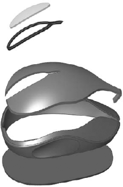
As an example of a multibody master model technique, a computer mouse is a complex shape, and the shape flows smoothly between parts. This is not conducive to in-context design, but works perfectly as a multibody master model. In-context design works best for replicating the locations of edges and holes, not the flow of a face. The multibody master model technique entails building the entire mouse as a single part, and then splitting it up into bodies that are in turn sent to different part files to have the detail features added.
Master model techniques are a product of four separate features or functions that have some similarities and some differences, and rely heavily on your knowledge of multiple bodies and surface functions. The four features are Split, Save Bodies, Insert Part, and Insert Into New Part. In turn, these four features can be categorized into Push and Pull type functions.
As an example of master model technique, consider the mouse model shown in Figure 28.1 which should be familiar by now. The overall shape is modeled as a single part, and is split into several bodies using multibody methods. Then, using these master model techniques, the individual bodies are used to create individual part files where detail features are added.
Pull functions are initiated from the child document and pull data from the master model (parent document) into the child. These functions insert a feature into the child that points to the parent, but do not insert a feature into the parent that points to the child.
The features that fall into this category are Insert Part and Insert Into New Part.
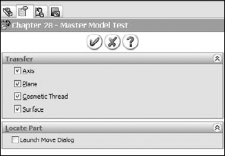
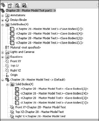
Figure 28.3 shows the FeatureManager of a part where the first feature is an Insert Part feature. All of the solid bodies are listed both under the normal Solid Bodies folder, and also under a second Solid Bodies folder under the inserted part icon. Other inserted items, such as surface bodies, planes, and axes, are also listed under the inserted part icon.
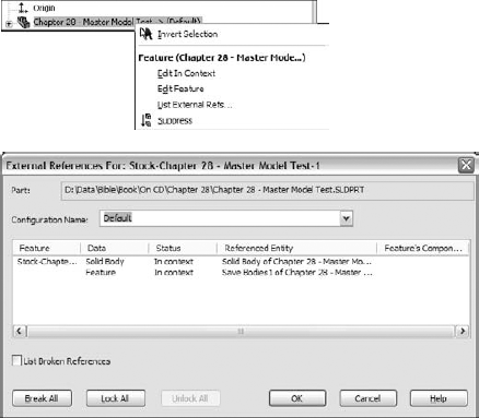
You cannot be selective about which bodies are pulled forward, but you can delete unwanted bodies once they have all been brought in. You can set configurations of the parent document in the External References dialog box, which is available through the RMB menu of the feature that is inserted into the child document FeatureManager. The External References dialog box is shown in Figure 28.4. If the overhead of bringing many bodies forward only to be deleted is an issue for you, then you can use parent part configurations to delete the bodies first; then, from the child using List External References, you can select which configuration to insert.
As the original inserted bodies are modified, and the names change, they are removed from the folder under the inserted part, and only appear in the body folders under the top level.
File management is a real issue with all of these master model functions; in fact, it may not be an exaggeration to say that it is the biggest problem that arises with them, although you could say the same thing about overall body management (for example, what happens when the number of bodies increases or decreases, when the bodies are split differently or change names, and so on).
One of the issues caused by not having some sort of a marker in the parent document is that if the parent is renamed, there is no way of knowing whether any children will be affected by the change. Further, a very dangerous situation exists when the child cannot find the parent (because the parent has been renamed or moved), the List External References dialog box cannot help you locate references. At that point, the parent cannot find the child (because of the way the feature works), and the child cannot find the parent (because of a user file management error combined with a bug); as a result, you do not even know where to look to fix the problem unless you just happen to know what went wrong.
Insert Into New Part qualifies as a Pull function because it does not create a feature in the FeatureManager of the parent file, even though it is actually initiated from the parent rather than from the child. This function does not have a drop-down menu location, nor does it have a toolbar button. You can initiate it from the RMB menu from either the Solid or Surface Bodies folders or from the individual bodies within the folders.
This gives Insert Into New Part both advantages and disadvantages over Insert Part. The advantages are that it can selectively insert either solid or surface bodies, or even selections of both types. You can Ctrl-select multiple bodies (solid or surface) to bring only the bodies forward that you need. However, it cannot bring forward planes or axes, or change the selection of what is brought forward after the feature is created. This is definitely a good news/bad news situation, but with this information, you can make a more informed decision about which function to use.
When Insert Into New Part is used to place bodies into a part, the bodies are not shown in the same way that the Insert Part function shows them. Figure 28.5 shows that the Stock feature symbols are used rather than the Inserted Part symbol since individual bodies are being placed rather than entire parts.
Push functions are initiated from the master model (parent document) and push data from the parent part out to a child part. The parent part is the master model, and the child part is the detail part file. A feature in the tree of the parent identifies the point at which the model is pushed out to the child, and the child file can be found from the parent.
The first feature in the child part is a Stock feature, and contains a reference back to the parent, so that the parent can be found from the child. The features that fall into this category are Split and Save Bodies.

The primary function of the Split feature is to split a single body into multiple bodies. This can be done with sketches, planes, or surface bodies, and is discussed in depth in Chapter 26.
There is not really an official name for this function, and so the name of the button, Save All Bodies, will do for our purposes. The Split feature can save both the pre-existing bodies and any bodies that result from the split as individual part files, using the Stock feature as the initial feature in the part.
The ability to save bodies out from the Split feature is a very convenient option, but there are some major drawbacks to working this way. If the number of bodies changes, or the method of creating those bodies changes, and the Split feature is edited, then the list of names of all of the files being saved to is reset. If the same names are entered into the PropertyManager, then the existing files are overwritten when you click the green check mark icon. This is not a problem if the overwritten parts do not have any dependent features within the part. However, it is a huge problem if there are dependent features. Dependent features are part of the end goal of using the Save All Bodies function, saving out the unfinished bodies, and finishing them with additional dependent features in their own files.
Fortunately, there is a workaround. It is clumsy, but so is redoing a lot of modeling work. The workaround involves temporarily moving the affected files to another folder before redefining the files in the Split feature's Save All Bodies function, and then moving the files back to overwrite the overwritten files. This retains all of the dependent features, and allows the Split feature to update.
After the Split feature has been created and you have saved bodies out of the Split feature, the RMB menu displays an option, Create Assembly, which puts all of the parts created from the bodies in the original part back together in the correct positions. Parts within the assemblies created this way are fixed in space with the same relationship to the assembly origin that they originally had as bodies to the part origin.
The Save Bodies feature is another function in SolidWorks that does not have a menu location, or toolbar button, but is accessed only from the RMB menu from the bodies folders. Save Bodies works similarly to giving path and filename information in the Resulting Bodies selection box of the Split feature. However, Save Bodies enables you to create an assembly right in the PropertyManager for the feature, rather than as a hidden feature with no record of the assembly name created by the feature. The PropertyManager for Save Bodies is shown in Figure 28.7.

Some of the concepts presented in this chapter may not make much sense until you see them applied to a specific situation. The goal of this tutorial is to demonstrate the strengths and weaknesses of the various functions, as well as to give you some practical experience with the file management issues that you will encounter. The mouse multibody part is used by each of the four tools so that you can become familiar with the differences in functionality by using the same starting point for each. To get some experience with these techniques, follow these steps:
To work with the Insert Part function, follow these steps:
Make sure that you have access to the material from the CD-ROM for Chapter 28. Create a new part, and insert the part named Chapter 28 – Mouse Base Part.SLDPRT. You can access Insert Part through the menus at Insert

Once the feature is accepted and in the tree, RMB click it and select List External Refs from the menu. The External References dialog box is shown in Figure 28.8, with the list of configurations displayed.
Select the Wheel configuration from the list.
Save and name the part file in such a way that it has the name of the technique used to create it (Insert Part) and the name of the body that it represents (such as Wheel).
Note
A little bit of preparation work has been done on your behalf to make this tutorial flow more smoothly. If you ever choose to do modeling in this way, then you will need to know what this preparation work entails.
In the mouse master model, a separate configuration was made for each body, and in that configuration, a Delete Body feature was created that deleted all of the bodies except one.
The alternative to this approach is to bring all of the bodies into each new part, and use a Delete Body feature in each child part that deletes all but the one body that is needed. The advantage to using configurations is that bringing in a single body theoretically decreases the overhead for the individual part files.
Repeat steps 1 through 4 for each of the five bodies in the master model.
If the mouse master model (Chapter 28 – Mouse Base Part) is open, then close it. In any of the child parts, the inserted part feature shown in the tree should have the Out Of Context symbol on it (- >?). RMB click the inserted part feature and select Edit In Context, which opens the master model.
Notice that from the master model, you have no way of knowing where the child parts are or even if any child parts exist. Notice also that there is no easy way to create an assembly.
Create a new assembly document.
Drop all of the individually created parts into the assembly by selecting them in Windows Explorer and dragging them onto the assembly Origin. This is probably the easiest way to create an assembly using the Insert Part feature.
Note
There is no link from the parent to the child, and so if the child part is renamed, the parent will not lose track of it. However, there is a link from the child to the parent, and so if the parent is renamed without the child being open at the same time, the child loses track of the parent.
If the parent is changed, the child does not update unless the symbol is showing In Context (->). If it is out of context, broken, or locked, the child does not update with the parent. Both documents need to be open at the same time to make the update happen (although they do not both need to be open when the original edit happens to the parent master model).
Save and close all of the parts and assemblies.

To work with the Insert Into New Part function, follow these steps:
For this feature, start from the master model. Open the part Chapter 28 – Mouse Base Part.SLDPRT. Make sure that the part is set to the Default configuration. If it is set to a different configuration, the insertion of bodies will not go as smoothly as it could.
Expand the Solid Bodies folder in the FeatureManager. RMB click the first body in the list (Wheel), and select Insert Into New Part from the menu.
Note
You could select multiple bodies and even combine solid and surface bodies to insert using this technique.
When prompted, name the new part using the same convention used in the previous tutorial, which was to use the name of the technique (Insert Into New Part) and the name of the body. In this part, leave the configuration setting in the External References dialog box to the Default configuration.
Repeat steps 1 through 3 for each of the bodies.
Right-click the Stock feature in the tree, and select Edit In Context. SolidWorks opens the master model part.
Note
Once again, there is no way back to the child document from the master model using the Insert Into New Part feature.
Create a new assembly document and use the same technique from the previous tutorial to put all of the parts in the assembly located from the Origin. Again, no automated assembly creation tool exists for this method.
Save all documents and close them.
To work with the Split function, follow these steps:
This time, start from a copy of the master model part. The Split feature makes additions to the model, and because you have already created assemblies based on the original, any additional features should be created using a copy of the part rather than the original. Copy it using the Copy and Paste feature in Windows Explorer, and rename the copy as Chapter 28 – Split Tutorial.
Note
It is best to copy and rename this document before continuing with the rest of the tutorial. Otherwise, you may encounter problems with the file references, from which it is difficult to recover.
With the newly copied and renamed document open, initiate the Split feature from Insert
Because the bodies already exist, there is no need for the Trim tools or Cut Part functions in the Split feature, only for the resulting bodies. To save the bodies to individual files, you must give each one a unique name. You can click the Save All Bodies button to automatically name them with generic names. The callout flags have a tendency to be difficult to discern where they are pointing. Once the names are all satisfactory, click OK to accept the feature.
Note
The Consume Cut Bodies option deletes the bodies of any bodies involved in the Split feature. For most purposes, you should turn this option off.
To automatically create an assembly with all of the components located in the proper location, right-click the Split feature in the Master Model FeatureManager, and select Create Assembly. Multiple Split features can be included in this command if bodies have been created by multiple Split features. Use the Browse button to locate and name the assembly. Click OK when you are done. Completing this step opens the assembly that you just named and located.
RMB click one of the parts in the assembly to open it. Notice that a Stock feature is used in the tree, and so it is possible to access the parent part and to change the parent part configuration used in the current part. RMB click the Stock feature and select Edit In Context.
With the master model open, RMB click the Split feature and select Edit Feature. From here, it is possible to see where each of the child parts is located.
If you rename any of the documents, then you should do this either by using SolidWorks Explorer or the Save As command with the other documents open as well. If you want to rename the parent part (master model), then make sure that all of the child parts are open as well (you can easily do this by opening the assembly; although the assembly was created from the master model, there is no direct link between the Split feature and the assembly).
Note
If the scheme by which the bodies are split changes in such a way that additional bodies are created, the Split feature may fail and need to be redefined. When this happens, the parts that were previously created will be overwritten. If features of the detail parts have been created within those files, then they will be overwritten as well. As mentioned earlier, the best workaround for this problem is to copy the files with the detail features in them out to another location, allow the Split feature to overwrite the files, and then move the copied files back to the original directory. This essentially overwrites the overwritten files, and all is well again.
You can also try this by rolling back before the final split and splitting another body off.
Save and close all of the files before proceeding.
To work with the Save Bodies function, follow these steps:
As before, create a copy of the original master model part and rename the copy Chapter 28 – Save Bodies Tutorial.
Open the renamed copy, and RMB click the Solid Bodies folder. Select Save Bodies from the menu. This function does not appear on a drop-down menu or toolbar, although it is slightly different from the other functions that do not appear on a toolbar or drop-down menu (Save Bodies does have its own icon that is used to denote the placeholder feature in the FeatureManager).
The Save Bodies PropertyManager is nearly identical to the lower section of the Split PropertyManager. The major addition in the Save Bodies dialog box is that of the Create Assembly function directly within the PropertyManager. The primary benefit of this addition is that it retains the name and path of the assembly in this interface so you can look it up later if necessary, remedying one of the weaknesses in the Split feature.
Note
In both the Split/Create Assembly and Save Bodies features, when an assembly is created, SolidWorks may rebuild the tree of the part as many times as you have bodies to save out. This may take some time for a complex model with a lot of bodies.
After finishing step 3, you are left in the reconstructed assembly. RMB click one of the parts and select Open Part to open it in its own window. Notice that the Stock feature has again been used to push a single body into the part.
RMB click the Stock feature, and select Edit In Context, which takes you back to the master model.
Save and close all of the files.
Each of these four functions has strengths and weaknesses. Because of this, there is no one feature that is clearly superior to the others. Most of the weaknesses have to do with file management, the types of data that they can work with, the ease of creating an assembly, and access to children from the parents. Unfortunately, I cannot offer a single solution that addresses all of the problems and retains each of the strengths.
I look to this area of the software being improved in a future release. If I were responsible for the functionality, I would consolidate the four flawed functions into a single feature that would be primarily used as a Push type master model function. This feature would have the ability to pre-select which bodies, reference geometry, and even sketches would be pushed out to the child part, and it would make every piece of it redefinable without losing existing data.