
IN THIS CHAPTER
Controlling layers
Controlling line format
Hiding and showing edges
Tutorial: Using drawing display tools
Most SolidWorks users have used AutoCAD at some point in their careers. AutoCAD is the Microsoft of CAD. Regardless of what you think of the company, the software, or the 2D world in general, AutoCAD has left its mark on CAD users of all kinds in the form of certain default expectations that people have about CAD software. A few common preconceptions are that layers, the Command Line, paper space/model space, and printing should be really difficult.
Given the ubiquity of AutoCAD in the market, it is not surprising that a few AutoCAD-like functions have found their way into the SolidWorks software. SolidWorks users, and even the SolidWorks Corporation, become a little defensive when you start talking about AutoCAD, or AutoCAD-like functionality. Maybe that is because we consider ourselves more highly evolved, having understood that 3D parametric design is a more sophisticated plane of existence than flatland 2D design.
When former AutoCAD users make the switch to SolidWorks, the questions start: Where is the Command Line, How do I put parts on layers, How do I change the background color to black, and my personal favorite, Where is the zero-radius trim?
This chapter addresses a couple of AutoCAD-like functions in the SolidWorks drawing environment. The goal is not to make the functions look or work or compare in any way to AutoCAD, but to simply to make them useful in the context of SolidWorks.
When you import data through DXF or DWG format files, the layers that exist in the original data are brought forward into SolidWorks, and you can use them in a similar way to the original AutoCAD usage. For example, you can turn layers on or off (visible or hidden), and you can change layer names, descriptions, color, line thickness, and line style.
The way you intend to use the imported data determines how you should open the file. If you only intend to view and print the drawing, then I would suggest using DWG Editor, which is installed with SolidWorks and enables you to do almost anything you can do with basic AutoCAD. It also has the advantage of having a familiar interface for the AutoCAD user (it even has a black background!). DWG Editor is available from the Start menu, by selecting Programs
If you need to integrate data from the imported document into a native SolidWorks drawing, then you can open the DWG file from the normal Open dialog box in SolidWorks.
Tip
If you want to make a 3D part from the 2D data in the DWG file, then you may want to import the drawing into the part sketch environment. This usually leads to some speed issues. If you prefer, sketch entities can also be copied from the drawing to the model sketch. You can even copy entities from DWG Editor to the SolidWorks part sketch. The sketch needs to be open in order to paste the sketch entities. In the case where imported 2D data is brought into the model sketch, you lose all of the layer information, because part and assembly documents do not allow layers.
The colors assigned to layers are often based on a black background, and so they can be difficult to see on a white background. The two ways of dealing with this are to change the SolidWorks drawing sheet color to something dark or to change the individual layer colors to something dark. Either method is easy, although if you have to send the 2D data back to its source, it may be best to temporarily change the drawing sheet color.
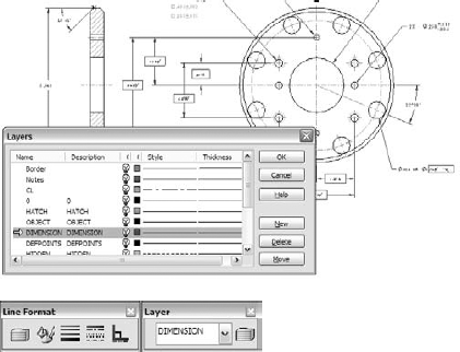
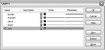
Figure 25.1 shows the layer interface with an imported drawing in the background. The colors have been changed here to improve visibility. The Layers dialog box is activated by the Layer Properties toolbar button, which is found on both the Layer and Line Format toolbars.
Be aware that many items in an imported drawing may come into SolidWorks as blocks. These items may need to be exploded before you can work with them. This is often the case with the drawing border, title block, or format.
One of the most obvious uses of layers is on the sheet format. The sketch lines used to create the border often have a heavier line weight and a different color that easily distinguishes them from model geometry.
You can assign layers in one of three ways:
Select existing items, and then select a layer from the drop-down list on the Layer toolbar.
Set the active layer and create new items.
While creating items such as sketch entities and annotations, select the layer for the new entity directly from the PropertyManager.
To set a layer to the active layer, double-click it from the Layers dialog box, as shown in Figure 25.1, or change it from the drop-down list on the Layer toolbar. When you assign an active layer, other newly created entities are also placed on the layer, not just sketch entities. Symbols, annotations, blocks, and other elements can also be put onto layers. If you are not particular about the layering scheme on a drawing, then it may be advisable to set the active layer to None, which is a valid option in the Layer toolbar drop-down list.
Another option when building a sheet format, or any other drawing function that requires sketching, is to use a special layer for construction geometry. This enables you to hide the layer when it is not being used, but it still maintains its relations. Hidden layers can be used in several other ways, for example, as standard notes on the drawing, and they can be easily turned on or off.
SolidWorks drawings have a tendency to be drab black-and-white drawings, in contrast to AutoCAD drawings, which often seem to take on a plethora of contrasting colors. Still, drawings do seem a little easier to comprehend when different types of items are colored differently, but in order for this to work, you must apply the coloring scheme consistently. Dimensions and annotations can also be placed on layers in the three ways described in the previous section (active layer, from the PropertyManager during creation, and through the drop-down list on the Layer toolbar). However, the line styles do not affect dimensions and notes, only the color and visibility settings.
Assembly drawings probably suffer the most from the monochromatic nature of most SolidWorks drawings because individual components can be difficult to identify when everything is the same color. This is why SolidWorks users typically color parts in the shaded model assembly window. It only makes sense that as users, we would want to do the same thing on the drawing.
An intuitive and easy workaround for this problem would seem to be to simply turn the drawing view to a wireframe mode in the same way that changing a drawing view to a shaded mode shows the parts in color. Unfortunately, wireframe on drawings always defaults to black edges. Even if you set a Display State using some wireframe parts where the wireframe displays in the same color as the shaded part in the assembly window, this still appears in black and white on the drawing.
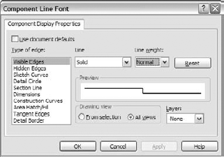
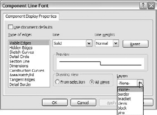
All that is left to display the components of an assembly in different colors while using a wireframe display mode is to set the Component Line Font options. (Line Fonts are covered in the next section.) The Component Line Font dialog box contains a Layer setting, which you can use to put a part on a layer. If the layer is set up with a color, then the part displays with that color in all views of the drawing, or in just the current view, depending on your settings. While it does take a little time to set up the individual layers for each part and then to set the parts to the layers, it is better than the alternative, which is to do nothing.
You can access the Component Line Font dialog box by right-clicking a component in a drawing view. The Component Line Font dialog box is shown in Figure 25.2.
In normal use, the Use Document Defaults option is selected and all of the settings in the dialog box are grayed out. To gain access to these settings, you must deselect the Use Document Defaults option, as shown in Figure 25.2.
Note
For more information on using line styles in the model, see Chapter 6.
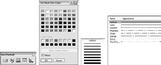
Figure 25.3 shows the Line Format toolbar along with the interfaces for Line Color, Line Thickness, and Line Style.
Note
The term line font refers to a combination of style, end cap, and thickness. Line fonts are set in the document-specific settings at Tools
You can specify the Line Format settings using two different methods. In the first method, you can set them with nothing selected, in which case they function like System Options (the new setting takes effect for all documents that are opened on the current computer). In the second method, if they are set with sketch entities or edges selected, then the settings apply only for the selected entities.
Note
If you change these settings with nothing selected, then the Line Format settings for color, thickness, and style function as system options.
Another option for the Line Font settings is the End Cap Style. This offers an important option, especially for thick lines. The three options are flat, round, and square, although the square style is usually appropriate. In the past, flat was the default setting, and there were no other options.
Note
The End Cap Style settings in Tools
Figure 25.4 shows the difference between the three options of End Cap Style.
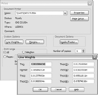
The Line Thickness settings are thin, normal, thick, and thick (2) to (6). Figure 25.5 shows the Line Weights dialog box, and the Print dialog box.
This is an area where the Help file will not only be little actual help, but may also steer you in the wrong direction. The Help does not appear to point to a location where you can set up the actual dimensional widths of printed lines assigned to the 9 thicknesses. The easiest to find direct mention of "line thickness" points to an obscure PhotoWorks setting. Other mentions of "line thickness" point to either the Layers or Line Format functions.
The correct information in the help is cleverly hidden, listed under "lines, weights." The settings for the line widths used to be on the Page Setup dialog box—the help for Page Setup still has a line thickness entry, even though the setting is no longer found there—but are now found in the Print dialog box.
Figure 25.5 shows the Print dialog box and the Line Weights dialog box.
Note
The Line Weights settings are system options, and are not document-specific. As a result, if drawings are printed from two different computers, and one of them has been customized, then the drawings may look different.
You can create custom line styles using the syntax shown on the Tools, Options, Document Properties, Line Style page. This is a document-specific setting, and so if you make a custom line style and want to use it in another document, then you have to save it out (as a *.sldlin file) and load it into the other document. Also, if you save your templates with this line style loaded, then you will not have to load the styles for any document made from that template. For more information about line styles, see Appendix B.
To use the Hide Edge tool, simply select the edges that you would like to hide, and click the Hide Edge toolbar button. To show the edges, click the Show Edge toolbar button; the cursor will now be able to select the hidden edges.
Some of the functions described in this chapter are difficult to understand until you actually use them. This tutorial guides you through the functions step by step so that you can see them in action. Start here:
From the CD-ROM, open the drawing called Chapter 25 – Tutorial.slddrw. Make sure that the Layer and Line Format toolbars are active and that the Hide Edge and Show Edge buttons are available on the Line Format toolbar.
RMB click a blank space and select Edit Sheet Format from the menu.
Window-select everything on the format and use the drop-down list on the Layers toolbar to assign the selection to the Border layer. Notice that this changes the color and the thickness of the sketch lines.
Note
Selection filters are inactive when you are editing drawings or formats; they are active only at odd times, such as when you edit a note.
RMB click a blank space and select Edit Sheet.
Click the Layer Properties button on either the Layer or Line Format toolbar. Add new layers for each of the part groups, bracket, clevis, pins, and blocks, assigning different colors to each layer. Figure 25.6 shows the Layers dialog box with these layers created.
Note
Be aware that creating new layers leaves the last layer that you created active, as indicated by the yellow arrow in Figure 25.6. There is no way to set the active layer to None from the Layers dialog box, and so this has to be done using the drop-down list in the Layer toolbar.
Set the active layer to None in the Layer toolbar drop-down list.
RMB click the Bracket part in one of the views and select Component Line Font. Deselect the Use Document Defaults option, and select the Bracket layer from the drop-down list in the lower-right corner of the dialog box, as shown in Figure 25.7. Make sure that the Drawing View option is set to All Views.
Repeat Step 7 for all of the components, assigning each component to its own layer. Notice how this makes the parts easier to identify.
Note
Alternatively, you could simply change the line style and weight (thickness—note the terminology inconsistencies here) for each component. This saves you creating the layers, but you lose the color settings.
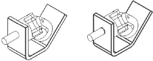
Open the Component Line Font dialog box for the Bracket part again. This time, set the Line Weight to Thick (6), and then click OK. You may have to rebuild the drawing to show the change (Ctrl+B or Ctrl+Q). Figure 25.8 shows a detail of the corners that are created by the thick lines. Notice the notches created at the corners.
These notches are supposed to be fixed using a new setting in SolidWorks 2007. In the menus, go to Tools

The image to the left in Figure 25.8 is the old setting with the draft quality view, and the image to the right is the new setting with the high quality view.
In the Component Line Font dialog box, set the Line Weight setting back to Default for the Bracket part, but keep it on the Bracket layer.
In the isometric view, Ctrl-click all of the tangent edges on the Bracket part, as shown in Figure 25.9. Click the Hide Edge toolbar button on the Line Format toolbar.
Click the Show Edge toolbar button. The PropertyManager message changes to indicate that you can now select hidden edges, and the hidden edges are shown. Ctrl-select the hidden edges and RMB click when you are done.

While SolidWorks is not primarily built around the strength of its 2D drawing functionality, it offers more capabilities than most users take advantage of. Layers in SolidWorks offer adequate functionality, but could be improved by some automation to put parts on layers automatically; this would enable SolidWorks to show the parts in wireframe with the same colors assigned to the solid.
Other line and edge display functionality is sometimes difficult to find or access, or may have obscure functions. Creating drawings that use color to make them easier to read should be easier in SolidWorks than it is in AutoCAD.