
Chapter 14. Depth Textures and Shadows
WHAT YOU’LL LEARN IN THIS CHAPTER:

Shadows are an important visual cue, both in reality and in rendered scenes. At a very basic level, shadows give us information about the location of objects in relation to each other and to light sources, even if the light sources are not visible in the scene. When it comes to games, shadows can make an already immersive environment downright spooky. Imagine turning the corner in a torch-lit dungeon and stepping into the shadow of your worst nightmare. Peter Pan had it easy.
In Chapter 5, “Color, Materials, and Lighting: The Basics,” we described a low-tech way of projecting an object onto a flat plane, in effect “squishing” it to appear as a shadow. Another technique utilizing the stencil buffer, known as shadow volumes, has been widely used, but it tends to require significant preprocessing of geometry and high fill rates to the stencil buffer. OpenGL 1.4 introduced a more elegant approach to shadow generation: shadow mapping.
The theory behind shadow mapping is simple. What parts of your scene would fall in shadow? Answer: The parts that light doesn’t directly hit. Think of yourself in the light’s position in your virtual scene. What would the light see if it were the camera? Everything the light sees would be lit. Everything else falls in shadow. Figure 14.1 will help you visualize the difference between the camera’s viewpoint and the light’s viewpoint.
Figure 14.1. The camera and the light have different perspectives on the scene.

When the scene is rendered from the light’s perspective, the side effect is a depth buffer full of useful information. At every pixel in the resulting depth buffer, we know the relative distance from the light to the nearest surface. These surfaces are lit by the light source. Every other surface farther away from the light source remains in shadow.
What we’ll do is take that depth buffer, copy it into a texture, and project it back on the scene, now rendered again from the normal camera angle. We’ll use that projected texture to automatically determine which parts of what objects are in light, and which remain in shadow. Sounds easy, but each step of this technique requires careful attention.
Be That Light
Our first step is to draw the scene from the light’s perspective. We’ll use several built-in GLUT objects to show off how well this technique works, even when casting shadows on nonplanar surfaces, such as other objects in the scene. You can change the viewpoint by manually setting the modelview matrix, but for this example, we use the gluLookAt helper function to facilitate the change:
gluLookAt(lightPos[0], lightPos[1], lightPos[2],
0.0f, 0.0f, 0.0f, 0.0f, 1.0f, 0.0f);
Fit the Scene to the Window
In addition to this modelview matrix, we also need to set up the projection matrix to maximize the scene’s size in the window. Even if the light is far away from the objects in the scene, to achieve the best utilization of the space in our shadow map, we would still like the scene to fill the available space. We’ll set up the near and far clipping planes based on the distance from the light to the nearest and farthest objects in the scene. Also, we’ll estimate the field of view to contain the entire scene as closely as possible:
GLfloat sceneBoundingRadius = 95.0f; // based on objects in scene
// Save the depth precision for where it's useful
lightToSceneDistance = sqrt(lightPos[0] * lightPos[0] +
lightPos[1] * lightPos[1] +
lightPos[2] * lightPos[2]);
nearPlane = lightToSceneDistance - sceneBoundingRadius;
// Keep the scene filling the depth texture
fieldOfView = (GLfloat)m3dRadToDeg(2.0f * atan(sceneBoundingRadius /
lightToSceneDistance));
glMatrixMode(GL_PROJECTION);
glLoadIdentity();
gluPerspective(fieldOfView, 1.0f, nearPlane, nearPlane + (2.0f *
sceneBoundingRadius));
Given our knowledge of the scene, we can determine a rough bounding radius for all objects. Our scene is centered around the origin at (0,0,0) with objects no more than 95 units away in any direction. Note that since the base plane won’t cast shadows on any of our other objects, we don’t need to render it into our shadow map. It was therefore not considered when choosing our bounding radius, either. Knowing the position of the light, which will be our eye position when rendering the light’s view of the scene, we choose near and far planes to be the distance in eye space from the light to the front and back of the scene’s bounding radius, respectively. Finally, the field of view can be estimated by taking twice the inverse tangent of the ratio between the scene’s bounding radius and the light-to-scene distance. For a thorough treatment of how to position and orient your shadow frustum to get best shadow map utilization, check out Robust Shadow Mapping with Light Space Perspective Shadow Maps by Michael Wimmer and Daniel Scherzer, which can be found in Section 4 of Shader X4, edited by Wolfgang Engel.
No Bells or Whistles, Please
When we draw the first pass of the scene, the light’s viewpoint, we don’t actually want to see it. We just want to tap into the resulting depth buffer. So we’ll draw to the back buffer and never bother swapping. We can further accelerate this pass by masking writes to the color buffer. And because all we care about is the depth values, we obviously don’t care about lighting, smooth shading, or anything else that isn’t going to affect the result. Shut it all off. In this sample, we don’t have any fixed functionality texture mapping or fragment shading in use. If we did, we would disable those as well for this depth pass. All we need to render is the raw geometry:
glShadeModel(GL_FLAT);
glDisable(GL_LIGHTING);
glDisable(GL_COLOR_MATERIAL);
glDisable(GL_NORMALIZE);
glColorMask(0, 0, 0, 0);
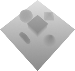
The output from drawing the scene from the light’s perspective is invisible, but Figure 14.2 illustrates via grayscale what the depth buffer contains.
Figure 14.2. If we could see the depth buffer, this is what it would look like.
A New Kind of Texture
We want to copy the depth values from the depth buffer into a texture for use as the shadow map. OpenGL allows you to copy color values directly into textures via glCopyTexImage2D. Until OpenGL 1.4, this capability was possible only for color values. But now depth textures are available.
Depth textures simply add a new type of texture data. We’ve had base formats with red, green, and blue color data and/or alpha, luminosity, or intensity. To this list, we now add a depth base format. The internal formats that can be requested include GL_DEPTH_COMPONENT16, GL_DEPTH_COMPONENT24, and GL_DEPTH_COMPONENT32, each reflecting the number of bits per texel. Typically, you’ll want a format that matches the precision of your depth buffer. OpenGL makes it easy by letting you use the generic GL_DEPTH_COMPONENT internal format that usually adopts whichever specific format matches your depth buffer.
After drawing the light’s view into the depth buffer, we want to copy that data directly into a depth texture. This saves us the trouble, and potential performance reduction, of using both glReadPixels and glTexImage2D:
glCopyTexImage2D(GL_TEXTURE_2D, 0, GL_DEPTH_COMPONENT,
0, 0, shadowWidth, shadowHeight, 0);
Note that drawing the light’s view and regenerating the shadow map needs to be done only when objects in the scene move or the light source moves. If the only thing moving is the camera angle, you can keep using the same depth texture. Remember, when only the camera moves, the light’s view of the scene isn’t affected. (The camera is invisible.) We can reuse the existing shadow map in this case. The only other time we regenerate the depth texture is when the window size changes, affording us the opportunity to generate a larger depth texture.
Size Matters
When it comes to depth textures, size matters. Earlier we discussed the importance of choosing a projection matrix that maximizes the scene’s size in the depth texture. A higher resolution depth texture will also yield more precise shadow results. Because we’re rendering the light’s viewpoint to our window’s back buffer as the basis for our depth texture, that limits its size. With a 1024×768 window, the biggest power-of-two size texture we can create is 1024×512:
void ChangeSize(int w, int h)
{
GLint i;
windowWidth = shadowWidth = w;
windowHeight = shadowHeight = h;
if (!npotTexturesAvailable)
{
// Find the largest power of two that will fit in window.
// Try each width until we get one that's too big
i = 0;
while ((1 << i) <= shadowWidth)
i++;
shadowWidth = (1 << (i-1));
// Now for height
i = 0;
while ((1 << i) <= shadowHeight)
i++;
shadowHeight = (1 << (i-1));
}
RegenerateShadowMap();
}
However, if GL_ARB_texture_non_power_of_two is supported (or OpenGL 2.0 is supported, which includes this extension), then we can create a texture that is the same size as the window. To generate a depth texture larger than the window size, an offscreen drawable, such as a Frame Buffer Object (FBO), is required. See Chapter 18, “Advanced Buffers,” where we add FBO support to our shadow mapping sample code. Adding FBO support to our sample code is left as an exercise for the reader!
Draw the Shadows First?!
Yes, we will draw the shadows first. But, you ask, if a shadow is defined as the lack of light, why do we need to draw shadows at all? Strictly speaking, you don’t need to draw them if you have a single spotlight. If you leave the shadows black, you’ll achieve a stark effect that may suit your purposes well. But if you don’t want pitch-black shadows and still want to make out details inside the shadowed regions, you’ll need to simulate some ambient lighting in your scene:
GLfloat lowAmbient[4] = {0.1f, 0.1f, 0.1f, 1.0f};
GLfloat lowDiffuse[4] = {0.35f, 0.35f, 0.35f, 1.0f};
glLightfv(GL_LIGHT0, GL_AMBIENT, lowAmbient);
glLightfv(GL_LIGHT0, GL_DIFFUSE, lowDiffuse);
// Draw objects in the scene, including base plane
DrawModels(GL_TRUE);
We’ve added a bit of diffuse lighting as well to help convey shape information. If you use only ambient lighting, you end up with ambiguously shaped solid-colored regions. Figure 14.3 shows the scene so far, entirely in shadow. Note that you won’t see this intermediate stage because we won’t swap buffers yet.
Figure 14.3. The entire scene is in shadow before the lit areas are drawn.

Some OpenGL implementations support an extension, GL_ARB_shadow_ambient, which makes this first shadow drawing pass unnecessary. In this case, both the shadowed regions and the lit regions are drawn simultaneously. More on that optimization later.
And Then There Was Light
Right now, we just have a very dimly lit scene. To make shadows, we need some brightly lit areas to contrast the existing dimly lit areas, turning them into shadows. But how do we determine which areas to light? This is key to the shadow mapping technique. After we’ve decided where to draw, we’ll draw brighter simply by using greater lighting coefficients, twice as bright as the shadowed areas:
GLfloat ambientLight[] = { 0.2f, 0.2f, 0.2f, 1.0f};
GLfloat diffuseLight[] = { 0.7f, 0.7f, 0.7f, 1.0f};
...
glLightfv(GL_LIGHT0, GL_AMBIENT, ambientLight);
glLightfv(GL_LIGHT0, GL_DIFFUSE, diffuseLight);
Projecting Your Shadow Map: The “Why”
The goal here is to project the shadow map (the light’s viewpoint) of the scene back onto the scene as if emitted from the light, but viewed from the camera’s position. We’re projecting those depth values, which represent the distance from the light to the first object hit by the light’s rays. Reorienting the texture coordinates into the right coordinate space is going to take a bit of math. If you care only about the “how” and not the “why,” you can safely skip over this section. We don’t blame you. Math is hard.
In Chapter 4, “Geometric Transformations: The Pipeline,” we explained the process of transforming vertices from object space to eye space, then to clip space, on to normalized device coordinates, and finally to window space. We have two different sets of matrices in play performing these transformations: one for the light view and the other for the regular camera view. Figure 14.4 shows the two sets of transformations in use.
Figure 14.4. The large arrow in the center shows the transformations we need to apply to our eye linear texture coordinates.

Any texture projection usually begins with eye linear texture coordinate generation. This process will automatically generate the texture coordinates. Unlike object linear texture coordinate generation, the eye linear coordinates aren’t tied to the geometry. Instead, it’s as if there is a film projector casting the texture onto the scene. But it doesn’t just project onto flat surfaces like a movie screen. Think about what happens when you walk in front of a projector. The movie is projected onto your irregularly shaped body. The same thing happens here.
We need to end up with texture coordinates that will index into our shadow map in the light’s clip space. We start off with our projected eye linear texture coordinates in the camera’s eye space. So we need to first backtrack to world space and then transform to the light’s eye space and finally to the light’s clip space. This transformation can be summarized by the following series of matrix multiplications:
M = Plight * MVlight * MVcamera-1
But wait, there’s more. The light’s clip space doesn’t quite bring us home free. Remember that clip space is in the range [–1,1] for each of the x, y, and z coordinates. The shadow map depth texture, like all standard 2D textures, needs to be indexed in the range [0,1]. Also, the depth texture values against which we’re going to be comparing are in the range [0,1], so we’ll also need our z texture coordinate in that range. A simple scale by one-half (S) and bias by one-half (B) will do the trick:
M = B * S * Plight * MVlight * MVcamera-1
If you’re unfamiliar with OpenGL matrix notation, you’re probably asking why these matrices are in reverse order. After all, we need to apply the inverse of the camera’s modelview first, and the bias by one-half translation is the last transformation we need. What’s the deal? It’s really simple, actually. OpenGL applies a matrix (M) to a coordinate (T) in a seemingly backward way, too. So you want to read everything right to left when thinking about the order of transformations being applied to your coordinate:
![]()
This is standard representation. Nothing to see here. Move along.
Projecting Your Shadow Map: The “How”
We understand what matrix transformations need to be applied to our eye linear-generated texture coordinate to have something useful to index into our shadow map texture. But how do we apply these transformations?
We’ll set up a texture matrix responsible for achieving the necessary texture coordinate manipulation. Then we’ll use the plane equations associated with eye linear texture coordinate generation to put that texture matrix to work. An alternative would be to establish a true texture matrix by calling glMatrixMode(GL_TEXTURE) followed by glLoadIdentity, glTranslatef, glScalef, glMultMatrixf, and so on; but that would incur an extra matrix multiply, whereas the eye linear plane equations will get applied regardless, so we may as well make full use of them!
To set up the texture matrix, we’ll start with an identity matrix and multiply in each of our required transformations discussed in the preceding section:
glGetFloatv(GL_PROJECTION_MATRIX, lightProjection);
...
glGetFloatv(GL_MODELVIEW_MATRIX, lightModelview);
...
// Set up texture matrix for shadow map projection,
// which will be rolled into the eye linear
// texture coordinate generation plane equations
M3DMatrix44f tempMatrix;
m3dLoadIdentity44(tempMatrix);
m3dTranslateMatrix44(tempMatrix, 0.5f, 0.5f, 0.5f);
m3dScaleMatrix44(tempMatrix, 0.5f, 0.5f, 0.5f);
m3dMatrixMultiply44(textureMatrix, tempMatrix, lightProjection);
m3dMatrixMultiply44(tempMatrix, textureMatrix, lightModelview);
// transpose to get the s, t, r, and q rows for plane equations
m3dTransposeMatrix44(textureMatrix, tempMatrix);
When setting our light’s projection and modelview matrices before drawing the light’s view, we conveniently queried and saved off these matrices so we could apply them later to the texture matrix. Our scale and bias operations to map [–1,1] to [0,1] are easily expressed as scales and translations.
But where’s the multiplication by the inverse of the camera’s modelview matrix? Glad you asked. OpenGL anticipated the need for this transformation when using eye linear texture coordinate generation. A post-multiply by the inverse of the current modelview matrix is applied automatically to the eye plane equations we provided. All you have to do is make sure your camera’s modelview is installed at the time you call glTexGenfv:
glMatrixMode(GL_MODELVIEW);
glLoadIdentity();
gluLookAt(cameraPos[0], cameraPos[1], cameraPos[2],
0.0f, 0.0f, 0.0f, 0.0f, 1.0f, 0.0f);
...
// Set up the eye plane for projecting the shadow map on the scene
glEnable(GL_TEXTURE_GEN_S);
glEnable(GL_TEXTURE_GEN_T);
glEnable(GL_TEXTURE_GEN_R);
glEnable(GL_TEXTURE_GEN_Q);
glTexGenfv(GL_S, GL_EYE_PLANE, &textureMatrix[0]);
glTexGenfv(GL_T, GL_EYE_PLANE, &textureMatrix[4]);
glTexGenfv(GL_R, GL_EYE_PLANE, &textureMatrix[8]);
glTexGenfv(GL_Q, GL_EYE_PLANE, &textureMatrix[12]);
...
glTexGeni(GL_S, GL_TEXTURE_GEN_MODE, GL_EYE_LINEAR);
glTexGeni(GL_T, GL_TEXTURE_GEN_MODE, GL_EYE_LINEAR);
glTexGeni(GL_R, GL_TEXTURE_GEN_MODE, GL_EYE_LINEAR);
glTexGeni(GL_Q, GL_TEXTURE_GEN_MODE, GL_EYE_LINEAR);
The Shadow Comparison
We have rendered our light view and copied it into a shadow map. We have our texture coordinates for indexing into the projected shadow map. The scene is dimly lit, ready for the real lights. The moment is near for completing our scene. We just need to combine the ingredients. First, there’s some important state we can “set and forget” during initialization.
// Hidden surface removal
glEnable(GL_DEPTH_TEST);
glDepthFunc(GL_LEQUAL);
We set the depth test to less than or equal so that we can draw the lit pass on top of the dim pass. Otherwise, because the geometry is identical, the lit pass would always fail the depth test, and nothing would show up after the dimly lit shadow pass.
// Set up some texture state that never changes
glGenTextures(1, &shadowTextureID);
glBindTexture(GL_TEXTURE_2D, shadowTextureID);
glTexParameteri(GL_TEXTURE_2D, GL_TEXTURE_WRAP_S, GL_CLAMP_TO_EDGE);
glTexParameteri(GL_TEXTURE_2D, GL_TEXTURE_WRAP_T, GL_CLAMP_TO_EDGE);
Then we generate and bind to our shadow map, which is the only texture used in this demo. We set our texture coordinate wrap modes to clamp to edge texels. It makes no sense to repeat the projection. For example, if the light affects only a portion of the scene, but the camera is zoomed out to reveal other unlit parts of the scene, you don’t want your shadow map to be repeated infinitely across the scene. You want your texture coordinates clamped so that only the lit portion of the scene has the shadow map projected onto it.
Depth textures contain only a single source component representing the depth value. But texture environments expect four components to be returned from a texture lookup: red, green, blue, and alpha. OpenGL gives you flexibility in how you want the single depth component mapped. Choices for the depth texture mode include GL_ALPHA (0,0,0,D), GL_LUMINANCE (D,D,D,1), and GL_INTENSITY (D,D,D,D). We’re going to need the depth broadcast to all four channels, so we choose the intensity mode:
glTexParameteri(GL_TEXTURE_2D, GL_DEPTH_TEXTURE_MODE, GL_INTENSITY);
Obviously, we need to enable texturing to put the shadow map into effect. We set the compare mode to GL_COMPARE_R_TO_TEXTURE. If we don’t set this, all we’ll get is the depth value in the texture. But we want more than that. We want the depth value compared to our texture coordinate’s R component:
// Set up shadow comparison
glEnable(GL_TEXTURE_2D);
glTexParameteri(GL_TEXTURE_2D, GL_TEXTURE_COMPARE_MODE,
GL_COMPARE_R_TO_TEXTURE);
The R component of the texture coordinate represents the distance from the light source to the surface of the object being rendered. The shadow map’s depth value represents the previously determined distance from the light to the first surface it hits. By comparing one to the other, we can tell whether the surface we are rendering is the first to be hit by a ray of light, or whether that surface is farther away from the light, and hence is in the shadow cast by the first, lit, surface:
D’ = (R <= D) ? 1 : 0
Other comparison functions are also available. In fact, OpenGL 1.5 enables you to use all the same relational operators that you can use for depth test comparisons. GL_LEQUAL is the default, so we don’t need to change it.
Another two settings we need to consider are the minification and magnification filters. Some implementations may be able to smooth the edges of your shadows if you enable bilinear filtering. On such an implementation, multiple comparisons are performed and the results are averaged. This is called percentage-closer filtering.
glTexParameteri(GL_TEXTURE_2D, GL_TEXTURE_MIN_FILTER, GL_LINEAR);
glTexParameteri(GL_TEXTURE_2D, GL_TEXTURE_MAG_FILTER, GL_LINEAR);
Great. We have a bunch of 0s and 1s. But we don’t want to draw black and white. Now what? Easy. We just need to set up a texture environment mode, GL_MODULATE, that multiplies the 0s and 1s by the incoming color resulting from lighting:
glTexEnvi(GL_TEXTURE_ENV, GL_TEXTURE_ENV_MODE, GL_MODULATE);
Finally, we’re done, right? We have drawn our lit areas now. But wait. Where shadows appear, we just drew black over our previous ambient lighting pass. How do we preserve the ambient lighting for shadowed regions? Alpha testing will do the trick. We asked for intensity depth texture mode. Therefore, our 0s and 1s are present in the alpha component as well as the color components. Using an alpha test, we can tell OpenGL to discard any fragments in which we didn’t get a 1:
// Enable alpha test so that shadowed fragments are discarded
glAlphaFunc(GL_GREATER, 0.9f);
glEnable(GL_ALPHA_TEST);
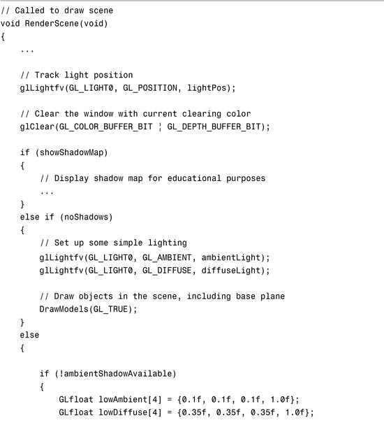
Okay. Now we’re done. Figure 14.5 shows the output from Listing 14.1, shadows and all.
Figure 14.5. A brightly lit pass is added to the previous ambient shadow pass.

Listing 14.1. Drawing the Ambient Shadow and Lit Passes of the Scene


Two Out of Three Ain’t Bad
In Listing 14.1, you’ll notice code hinging on the ambientShadowAvailable variable. The minimum requirement for the rest of this example is OpenGL 1.4 support, or at least support for the GL_ARB_shadow extension. If, however, your implementation supports the GL_ARB_shadow_ambient extension, you can cut down on the amount of work significantly.
Currently, we’ve described three rendering passes: one to draw the light’s perspective into the shadow map, one to draw the dimly lit ambient pass, and one to draw the shadow-compared lighting. Remember, the shadow map needs to be regenerated only when the light position or objects in the scene change. So sometimes there are three passes, and other times just two. With GL_ARB_shadow_ambient, we can eliminate the ambient pass entirely.
Instead of 0s and 1s resulting from the shadow comparison, this extension allows us to replace another value for the 0s when the comparison fails. So if we set the fail value to one-half, the shadowed regions are still halfway lit, the same amount of lighting we were previously achieving in our ambient pass:
if (ambientShadowAvailable)
glTexParameterf(GL_TEXTURE_2D, GL_TEXTURE_COMPARE_FAIL_VALUE_ARB,
0.5f);
This way, we also don’t need to enable the alpha test.
A Few Words About Polygon Offset
Even on a surface closest to the light source, you will always discover minor differences in the values associated with the R texture coordinate, representing the surface to light distance, and the shadow map’s depth value. This can result in “surface acne,” whereby the projection of a discretely sampled shadow map onto a continuous surface leads to the surface shadowing itself. You can mitigate this problem by applying a depth offset (a.k.a. polygon offset) when rendering into the shadow map:
// Overcome imprecision
glEnable(GL_POLYGON_OFFSET_FILL);
...
glPolygonOffset(factor, 0.0f);
Although the polygon offset will help guarantee that surfaces that shouldn’t be shadowed won’t be, it also artificially shifts the position of shadows. A balance needs to be struck when it comes to polygon offset usage. Figure 14.6 illustrates what you’ll see if you don’t use enough polygon offset.
Figure 14.6. “Shadow acne” can be cleared up with liberal application of polygon offset.

For an in depth discussion of shadow acne, refer to Eliminate Surface Acne with Gradient Shadow Mapping by Christian Schüler, published in Shader X4, edited by Wolfgang Engel.
Summary
Shadow mapping is a useful technique for achieving realistic lighting without a lot of additional processing. The light’s viewpoint can be used to determine which objects are lit and which remain in shadow. Depth textures are special textures designed to store the contents of your depth buffer for use as a shadow map. Eye linear texture coordinate generation is the basis for projected textures. A texture matrix encoded into the eye linear plane equations can be used to reorient the texture coordinates back into the light’s clip space. Shadow comparison can be used to make the distinction between shadowed and lit regions. The GL_ARB_shadow_ambient extension can be used to reduce the number of passes that must be rendered.