
8
![]()
Nonlinear Fiber Ring Lasers
![]()
Le Nguyen Binh
Hua Wei Technologies, European Research Center, Munich, Germany
CONTENTS
8.3 Active Mode-Locked Fiber Ring Laser by Rational Harmonic Detuning
8.3.1 Rational Harmonic Mode Locking
8.4 Repetition-Rate Multiplication Ring Laser Using Temporal Diffraction Effects
8.4.2 Uniform Lasing Mode Amplitude Distribution
8.4.3 Gaussian Lasing Mode Amplitude Distribution
8.4.4 Effects of Filter Bandwidth
![]()
8.1 Overview
This chapter presents the operational principles and implementation of mode-locked fiber lasers operating in the nonlinear region, whether via the optical saturated amplification or the photonic interactions of the pump sources and generated lightwaves. Harmonic and regenerative mode-locked types for 10 and 40 G-pulse/s employing the harmonic detuning technique for generating up to 200 G-pulses/s, and harmonic repetition multiplication using temporal diffraction are described. An ultrastable mode-locked laser operating at 10 GHz repetition rate has been designed, constructed, and tested. The laser generates an optical pulse train of 4.5 ps pulse width when the modulator is biased at the phase quadrature quiescent region. Long-term stability of amplitude and phase noise indicates that the optical pulse source can produce an error-free pattern in a self-locking mode for more than 20 hours, the most stable photonic fiber ring laser reported to date.
The repetition rate is demonstrated up to 200 G-pulse/s using the harmonic detuning mechanism in a nonlinear fiber ring laser. In this system, the system operation under the rational harmonic mode-locking is analyzed using the phase plane technique in control engineering. Furthermore, we examine the harmonic distortion contribution to this system performance. The multiplication factor of 660× and 1230× of the fundamental rate of a 100 MHz pulse train can be achieved, hence 66 GHz and 123 GHz pulse rate. The system behavior of group velocity dispersion repetition rate multiplication is proven as one of the principal mechanisms. Stability and the transient response of the multiplied pulses are studied using the phase plane technique.
Nonlinear fiber lasers can be used to generate bistable operations and multibound solitons based on the nonlinearity in the ring cavity. Experimental and theoretical generation of multisoliton bound states in an active frequency modulation (FM) mode-locked fiber laser will be described in Chapter 3 in which not only bound soliton pairs but also triple- and quadruple-soliton bound states can be generated.
![]()
8.2 Introduction
Generation of ultrashort optical pulses with a multiple gigabits repetition rate is critical for ultrahigh bit rate optical communications, particularly for the next generation of terabits/sec optical fibers systems. As the demand for the bandwidth of the optical communication systems increases, the generation of short pulses with an ultrahigh repetition rate becomes increasingly important in the coming decades.
The mode-locked fibers laser offers a potential source of such a pulse train. Although the generation of ultrashort pulses by mode locking of a multimodal ring laser is well known, the applications of such short pulse trains in multigigabits/sec optical communications challenges its designers on its stability and spectral properties. Recent reports on the generation of short pulse trains at repetition rates in order of 40 Gb/s, possibly higher in the near future [1], motivates us to design and experiment with these sources in order to evaluate whether they can be employed in practical optical communications systems.
Further, the interest of multiplexed transmission at 160 Gb/s and higher in the foreseeable future requires us to experiment with an optical pulse source having a short pulse duration and high repetition rates. This report describes laboratory experiments of a mode-locked fiber ring laser (MLFRL), initially with a repetition rate of 10 GHz and preliminary results of higher multiple repetition rates up to 40 GHz. The mode-locked ring lasers reported hereunder adopt an active mode-locking scheme whereby partial optical power of the output optical waves is detected and filtered and a clock signal is recovered at the desired repetition rate. It is then used as a radio-frequency (RF) drive signal to the intensity modulator incorporated in the ring laser. A brief description on the principle of operation of the MLFRL is given in the next section followed by a description of the mode-locked laser experimental setup and characterization.
Active mode-locked fiber lasers remain as a potential candidate for the generation of such pulse trains. However, the pulse repetition rate is often limited by the bandwidth of the modulator used or the RF oscillator that generates the modulation signal. Hence, some techniques have been proposed to increase the repetition frequency of the generated pulse trains. Rational harmonic mode locking is widely used to increase the system repetition frequency [1–3]. A 40 GHz repetition frequency has been obtained with fourth-order rational harmonic mode locking at 10 GHz base band modulation frequency [2]. Wu and Dutta [3] reported 22nd-order rational harmonic detuning in the active mode-locked fiber laser, with 1 GHz base frequency, leading to 22 GHz pulse operation. This technique is simple and achieved by applying a slight deviated frequency from the multiple of fundamental cavity frequency. Nevertheless, it is well known that it suffers from inherent pulse amplitude instability as well as poor long-term stability. Therefore, pulse amplitude equalization techniques are often applied to achieve better system performance [3–5].
Other than this rational harmonic detuning, other techniques have been reported and used to achieve the same objective. The fractional temporal Talbot-based repetition rate multiplication technique [6,7] uses the interference effect between the dispersed pulses to achieve the repetition rate multiplication. The essential element of this technique is the dispersive medium, such as linearly chirped fiber grating (LCFG) [6,8] and dispersive fiber [9–11]. Intracavity optical filtering [12,13] uses modulators and a high finesse Fabry–Perot filter (FFP) within the laser cavity to achieve a higher repetition rate by filtering out certain lasing modes in the mode-locked laser. Other techniques used in repetition rate multiplication include higher-order FM mode locking [14], optical time domain multiplexing [15], and so forth.
The stability of a high repetition rate pulse train generated is one of the main concerns for practical multi-Giga bits/sec optical communications system. Qualitatively, a laser pulse source is considered as stable if it is operating at a state where any perturbations or deviations from this operating point are not increased but suppressed. Conventionally the stability analyses of such laser systems are based on the linear behavior of the laser in which we can analyze the system behavior in both time and frequency domains. However, when the mode-locked fiber laser is operating under a nonlinear regime, none of these standard approaches can be used, because the direct solution of a nonlinear different equation is generally impossible, hence frequency domain transformation is not applicable. Some inherent nonlinearities in the fiber laser may affect its stability and performance, such as the saturation of the embedded gain medium, nonquadrature biasing of the modulator, nonlinearities in the fiber, and so forth, hence, a nonlinear stability approach should be used in any laser stability analysis.
In the next section, we focus on the stability and transient analyses of the rational harmonic mode locking in the fiber ring laser system using the phase plane method, which is commonly used in nonlinear control systems. This technique was previously used in [11] to study the system performance of the fractional temporal Talbot repetition rate multiplication systems. It has been shown that it is an attractive tool in system behavior analysis. However, it has not been used in the rational harmonic mode-locking fiber laser system. In the next section, the rational harmonic detuning technique is briefly discussed.
Rational harmonic detuning [3,16] is achieved by applying a slight deviated frequency from the multiple of fundamental cavity frequency. A 40 GHz repetition frequency has been obtained by [3] using a 10 GHz base band modulation frequency with fourth-order rational harmonic mode locking. This technique is simple in nature. However, this technique suffers from inherent pulse amplitude instability, which includes both amplitude noise and inequality in pulse amplitude; furthermore, it gives poor long-term stability. Hence, pulse amplitude equalization techniques are often applied to achieve better system performance [2,4,5]. The fractional temporal Talbot-based repetition rate multiplication technique [4–8] uses the interference effect between the dispersed pulses to achieve the repetition rate multiplication. The essential element of this technique is the dispersive medium, such as linearly chirped fiber grating (LCFG) [8,16] and single-mode fiber [8,9]. This technique will be discussed further in Section 8.2. Intracavity optical filtering [13,14] uses modulators and a high finesse Fabry–Perot filter (FFP) within the laser cavity to achieve a higher repetition rate by filtering out certain lasing modes in the mode-locked laser. Other techniques used in repetition rate multiplication include higher-order FM mode locking [13], optical time domain multiplexing, and so forth.
Although Talbot-based repetition rate multiplication systems are based on the linear behavior of the laser, there are still some inherent nonlinearities affecting its stability, such as the saturation of the embedded gain medium, nonquadrature biasing of the modulator, nonlinearities in the fiber, and so forth; hence, a nonlinear stability approach must be adopted. In Section 8.3, we focus on the stability and transient analyses of the group velocity dispersion (GVD) multiplied pulse train using the phase plane analysis of nonlinear control analytical technique [2]. This section uses the phase plane analysis described in Chapter 2 to study the stability and transient performances of the GVD repetition rate multiplication systems. In Section 8.2, the GVD repetition rate multiplication technique is briefly given. Section 8.3 describes the experimental setup for the repetition rate multiplication. This section also investigates the dynamic behavior of the phase plane of the GVD multiplication system, followed by some simulation results. Finally, some concluding remarks and possible future developments for this type of laser are given.
![]()
8.3 Active Mode-Locked Fiber Ring Laser by Rational Harmonic Detuning
In this section we investigate the system behavior of rational harmonic mode-locking in the fiber ring laser using the phase plane technique of the nonlinear control engineering. Furthermore, we examine the harmonic distortion contribution to this system performance. We also demonstrate 660× and 1230× repetition rate multiplications on 100 MHz pulse train generated from an active harmonically mode-locked fiber ring laser, hence achieving 66 GHz and 123 GHz pulse operations by using rational harmonic detuning, which is the highest rational harmonic order reported to date.
8.3.1 Rational Harmonic Mode Locking
In an active harmonically mode-lock fiber ring laser, the repetition frequency of the generated pulses is determined by the modulation frequency of the modulator, fm = qfc, where q is the qth harmonic of the fundamental cavity frequency, fc, which is determined by the cavity length of the laser, fc = c/nL, where c is the speed of light, n is the refractive index of the fiber, and L is the cavity length. Typically, fc is in the range of kHz or MHz. Hence, in order to generate a GHz pulse train, mode locking is normally performed by modulation in the states of q >> 1 (i.e., q pulses circulating within the cavity), which is known as harmonic mode locking. By applying a slight deviation or a fraction of the fundamental cavity frequency, Df = fc/m, where m is the integer, the modulation frequency becomes
![]()
This leads to an m-times increase in the system repetition rate, fr = mfm, where fr is the repetition frequency of the system [2]. When the modulation frequency is detuned by an m fraction, the contributions of the detuned neighboring modes are weakened, only every mth lasing mode oscillates in phase and the oscillation waveform maximums accumulate, hence achieving m times higher repetition frequency. However, the small but not negligible detuned neighboring modes affect the resultant pulse train, which leads to uneven pulse amplitude distribution and poor long-term stability. This is considered as harmonic distortion in our modeling, and it depends on the laser linewidth and amount detuned (i.e., a fraction m). The amount of the allowable detunable range or rather the obtainable increase in the system repetition rate by this technique is very much limited by the amount of harmonic distortion. When the amount of frequency detuned is too small relative to the modulation frequency, that is very high m, contributions of the neighboring lasing modes become prominent, thus reducing the repetition rate multiplication capability significantly. In other words, no repetition frequency multiplication is achieved when the detuned frequency is unnoticeably small. Often the case, it is considered as the system noise due to improper modulation frequency tuning. In addition, the pulse amplitude fluctuation is determined by this harmonic distortion.
8.3.2 Experimental Setup
In general, the experimental setup of the active harmonically mode-locked fiber ring laser is similar to Figure 8.1. The principal element of the laser is an optical open loop with an optical gain medium, a Mach–Zehnder amplitude modulator (MZM), an optical amplifier to supply sufficient energy of photons, an optical polarization controller (PC), an optical bandpass filter (BPF), optical couplers, and other associated optics.
The gain medium used in our fiber laser system is an erbium-doped fiber amplifier (EDFA) with the saturation power of 16 dBm. A polarization-independent optical isolator is used to ensure unidirectional lightwave propagation as well as to eliminate back-reflections from the fiber splices and optical connectors. A free space filter with 3 dB bandwidth of 4 nm at 1555 nm is inserted into the cavity to select the operating wavelength of the generated signal and to reduce the noise in the system. In addition, it is responsible for the longitudinal modes selection in the mode-locking process. The birefringence of the fiber is compensated by a polarization controller, which is also used for the polarization alignment of the linearly polarized lightwave before entering the planar structure modulator for better output efficiency. Pulse operation is achieved by introducing an asymmetric coplanar traveling wave 10 Gb/s lithium niobate, Ti:LiNbO3 Mach–Zehnder amplitude modulator into the cavity with half-wave voltage, Vp of 5.8 V and insertion loss of £7 dB. The modulator is DC biased near the quadrature point and not more than the Vp such that it operates around the linear region of its characteristic curve. The modulator is driven by a 100 MHz, 100 ps step recovery diode (SRD), which is in turn driven by an RF amplifier (RFA), a RF signal generator. The modulating signal generated by the step recovery diode is a ~1% duty cycle Gaussian pulse train. The output coupling of the laser is optimized using a 10/90 coupler. Then 90% of the optical field power is coupled back into the cavity ring loop, while the remaining portion is taken out as the output of the laser and is analyzed.

FIGURE 8.1
Setup of a THz regenerative mode-locked fiber ring laser using nonlinear effects such as parametric amplification sequence incorporating the proposed controller.
8.3.3 Phase Plane Analysis
A nonlinear system frequently has more than one equilibrium point. It can also oscillate at a fixed amplitude and fixed period without external excitation. This oscillation is called the limit cycle. However, limit cycles in nonlinear systems are different from linear oscillations. First, the amplitude of self-sustained excitation is independent of the initial condition, while the oscillation of a marginally stable linear system has its amplitude determined by the initial conditions. Second, marginally stable linear systems are very sensitive to changes, while limit cycles are not easily affected by parameter changes [31].
As described in Chapter 2, phase plane analysis is a graphical method of studying second-order nonlinear systems. The result is a family of system motion of trajectories on a two-dimensional plane, which allows us to visually observe the motion patterns of the system. Nonlinear systems can display more complicated patterns in the phase plane, such as multiple equilibrium points and limit cycles. In the phase plane, a limit cycle is defined as an isolated closed curve. The trajectory has to be both closed, indicating the periodic nature of the motion, and isolated, indicating the limiting nature of the cycle [17–31].
The system modeling of the rational harmonic mode-locked fiber ring laser system is implemented on the following assumptions: (1) detuned frequency is perfectly adjusted according to the fraction number required, (2) there is small harmonic distortion, (3) no fiber nonlinearity is included in the analysis, (4) no other noise sources are involved in the system, and (5) there is Gaussian lasing mode amplitude distribution analysis.
The phase plane of a perfect 10 GHz mode-locked pulse train without any frequency detune is shown in Figure 8.2 and the corresponding pulse train is shown in Figure 8.3a. The shape of the phase plane exposes the phase between the displacement and its derivative. From the phase plane obtained, one can easily observe that the origin is a stable node and the limit cycle around that vicinity is a stable limit cycle, hence leading to stable system trajectory. The 4× multiplication pulse trains (i.e., m = 4) without and with 5% harmonic distortion are shown in Figures 8.3b and 8.3c. Their corresponding phase planes are shown in Figures 8.4a and 8.4b. For the case of zero harmonic distortion, which is the ideal case, the generated pulse train is perfectly multiplied with equal amplitude and the phase plane has stable symmetry periodic trajectories around the origin. However, for the practical case (i.e., with 5% harmonic distortion), it is obvious that the pulse amplitude is unevenly distributed, which can be easily verified with the experimental results obtained in [3]. Its corresponding phase plane shows more complex asymmetry system trajectories.

FIGURE 8.2
Phase plane of a 10 GHz mode-locked pulse train. (Solid line, real part of the energy; dotted line, imaginary part of the energy; x-axes, E(t); and y-axes, E′(t))
One may naively think that the detuning fraction, m, could be increased to a very large number, so a very small frequency deviated, Δ f, so as to obtain a very high repetition frequency. This is only true in the ideal world, if no harmonic distortion is present in the system. However, this is unreasonable for a practical mode-locked laser system.
We define the percentage fluctuation, %F as follows:
![]()

FIGURE 8.3
Normalized pulse propagation of original pulse (a) detuning fraction of 4, with 0%, (b) 5%, (c) harmonic distortion noise.

FIGURE 8.4
Phase plane of detuned pulse train, m = 4, 0% harmonic distortion (a), and 5% harmonic distortion (b) (solid line, real part of the energy; dotted line, imaginary part of the energy; x-axes, E(t); and y-axes, E′(t)).

FIGURE 8.5
Relationship between the amplitude fluctuation and the percentage harmonic distortion (diamond, m = 2; square, m = 4; triangle, m = 8).
where Emax and Emin are the maximum and minimum peak amplitudes of the generated pulse train. For any practical mode-locked laser system, fluctuations above 50% should be considered as poor laser system design. Therefore, this is one of the limiting factors in a rational harmonic mode-locking fiber laser system. The relationships between the percentage fluctuation and harmonic distortion for three multipliers (m = 2, 4, and 8) are shown in Figure 8.4. Thus, the obtainable rational harmonic mode-locking is very much limited by the harmonic distortion of the system. For 100% fluctuation, it means no repetition rate multiplication, but with additional noise components (see Figure 8.5); a typical pulse train and its corresponding phase plane are shown in Figure 8.6 (lower plot) and Figure 8.7 with m = 8 and 20% harmonic distortion. The asymmetric trajectories of the phase graph explain the amplitude unevenness of the pulse train. Furthermore, it shows a more complex pulse formation system. Thus, it is clear that for any harmonic mode-locked laser system, the small side pulses generated are largely due to improper or not exact tuning of the modulation frequency of the system. An experimental result is depicted in Figure 8.10 for a comparison.
8.3.4 Demonstration
By careful adjustment of the modulation frequency, polarization, gain level, and other parameters of the fiber ring laser, we managed to obtain the 660th and 1230th order of rational harmonic detuning in the mode-locked fiber ring laser with a base frequency of 100 MHz, hence achieving 66 GHz and 123 GHz repetition frequency pulse operation. The autocorrelation traces and optical spectrums of the pulse operations are shown in Figure 8.8. With Gaussian pulse assumption, the obtained pulse widths of the operations are 2.5456 ps and 2.2853 ps, respectively. For the 100 MHz pulse operation (i.e., without any frequency detune), the generated pulse width is about 91 ps. Thus, we achieved not only an increase in the pulse repetition frequency, but also a decrease in the generated pulse widths. This pulse narrowing effect is partly due to the self-phase modulation effect of the system, as observed in the optical spectrums. Another reason for this pulse shortening is stated by Haus in [18], where the pulse width is inversely proportional to the modulation frequency as follows:
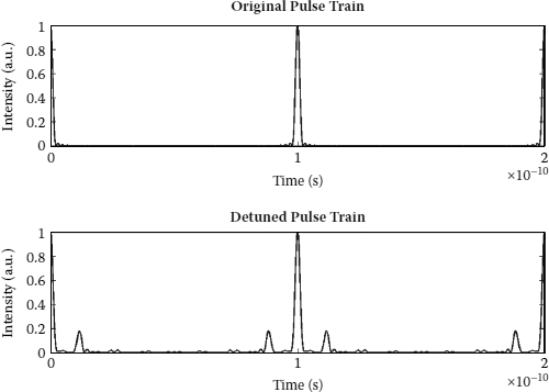
FIGURE 8.6
10 GHz pulse train (upper plot); pulse train with m = 8 and 20% harmonic distortion (lower plot).

FIGURE 8.7
Phase plane of the pulse train with m = 8 and 20% harmonic distortion.
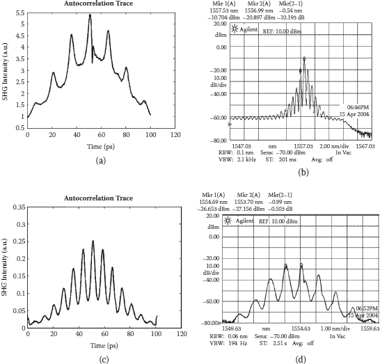
FIGURE 8.8
Autocorrelation traces of 66 GHz (a) and 123 GHz (c) pulse operation; optical spectrums of 66 GHz (b) and 123 GHz (d).
![]()
where t is the pulse width of the mode-locked pulse, wm is the modulation frequency, g is the gain coefficient, M is the modulation index, and wg is the gain bandwidth of the system. In addition, the duty cycle of our Gaussian modulation signal is ~1%, which is very much less than 50%, this leads to a narrow pulse width, too. Besides the uneven pulse amplitude distribution, a high level of pedestal noise is also observed in the obtained results.
For 66 GHz pulse operation, a 4 nm bandwidth filter is used in the setup, but it is removed for the 123 GHz operation. It is done so to allow more modes to be locked during the operation and, thus, to achieve better pulse quality. In contrast, this increases the level of difficulty significantly in the system tuning and adjustment. As a result, the operation is very much determined by the gain bandwidth of the EDFA used in the laser setup.
The simulated phase planes for the above pulse operation are shown in Figure 8.9. They are simulated based on the 100 MHz base frequency, 10 round-trips condition, and 0.001% of harmonic distortion contribution. There is no stable limit cycle in the phase graphs obtained; hence, the system stability is hardly achievable, which is a known fact in the rational harmonic mode locking. Asymmetric system trajectories are observed in the phase planes of the pulse operations. This reflects the unevenness of the amplitude of the pulses generated. Furthermore, more complex pulse formation process is also revealed in the phase graphs obtained.
By a very small amount of frequency deviation, or improper modulation frequency tuning in the general context, we can generate a pulse train with ~100 MHz modulation frequency with very short adjacent side pulses as shown in Figure 8.10. It is rather similar to Figure 8.6 (lower plot) despite the level of pedestal noise in the actual case. This is mainly because we do not consider other sources of noise in our modeling, except the harmonic distortion.

FIGURE 8.9
Phase plane of the 66 GHz (a) and 123 GHz (b) pulse train with 0.001% harmonic distortion noise.
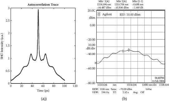
FIGURE 8.10
Autocorrelation trace (a) and optical spectrum (b) of slight frequency detune in the mode-locked fiber ring laser.
8.3.5 Remarks
We demonstrated a 660th and 1230th order of rational harmonic mode locking from a base modulation frequency of 100 MHz in the erbium-doped fiber ring laser, hence achieving 66 GHz and 123 GHz pulse repetition frequency. To the best of our knowledge, this is the highest rational harmonic order obtained to date. Besides the repetition rate multiplication, we also obtain a high pulse compression factor in the system, ~35× and 40× relative to the nonmultiplied laser system.
In addition, we use phase plane analysis to study the laser system behavior. From the analysis model, the amplitude stability of the detuned pulse train can only be achieved under a negligible or no harmonic distortion condition, which is the ideal situation. The phase plane analysis also reveals the pulse-forming complexity of the laser system.
![]()
8.4 Repetition-Rate Multiplication Ring Laser Using Temporal Diffraction Effects
The pulse repetition rate of a mode-locked ring laser is usually limited by the bandwidth of the intracavity modulator. Hence, a number of techniques have to be used to increase the repetition frequency of the generated pulse train. Rational harmonic detuning [3,16] is achieved by applying a slight deviated frequency from the multiple of a fundamental cavity frequency. A 40 GHz repetition frequency has been obtained by [3] using a 10 GHz base band modulation frequency with fourth-order rational harmonic mode locking. This technique is simple in nature. However, this technique suffers from inherent pulse amplitude instability, which includes both amplitude noise and inequality in pulse amplitude, furthermore, it gives poor long-term stability. Hence, pulse amplitude equalization techniques are often applied to achieve better system performance [2,4,5]. The fractional temporal Talbot-based repetition rate multiplication technique [4–8] uses the interference effect between the dispersed pulses to achieve the repetition rate multiplication. The essential element of this technique is the dispersive medium, such as linearly chirped fiber grating (LCFG) [8,16] and single-mode fiber [8,9]. This technique is discussed further in Section 8.2. Intracavity optical filtering [13,14] uses modulators and an FFP within the laser cavity to achieve a higher repetition rate by filtering out certain lasing modes in the mode-locked laser. Other techniques used in repetition rate multiplication include higher-order FM mode-locking [13], optical time domain multiplexing, and so forth.
The stability of a high repetition rate pulse train generated is one of the main concerns for practical multi-Giga bits/sec optical communications systems. Qualitatively, a laser pulse source is considered as stable if it is operating at a state where any perturbations or deviations from this operating point is not increased but suppressed. Conventionally the stability analyses of such laser systems are based on the linear behavior of the laser in which we can analytically analyze the system behavior in both time and frequency domains. However, when the mode-locked fiber laser is operating under a nonlinear regime, none of these standard approaches can be used, because the direct solution of a nonlinear different equation is generally impossible, hence frequency domain transformation is not applicable. Although Talbot-based repetition rate multiplication systems are based on the linear evolution of the laser, there are still some inherent nonlinearities affecting its stability, such as the saturation of the embedded gain medium, nonquadrature biasing of the modulator, nonlinearities in the fiber, and so forth; hence, a nonlinear stability approach must be adopted.
We investigate the stability and transient analyses of the GVD multiplied pulse train using the phase plane analysis of the nonlinear control analytical technique [2]. This is the first time, to the best of our knowledge, that the phase plane analysis in the field of digital control can be used to analyze the stability and transient performances of the GVD repetition rate multiplication systems.
The stability and the transient response of the multiplied pulses are studied using the phase plane technique of nonlinear control engineering. We also demonstrated a four times repetition rate multiplication on a 10 Gbits/s pulse train generated from the active harmonically mode-locked fiber ring laser, hence achieving a 40 Gbits/s pulse train by using the fiber GVD effect. It has been found that the stability of the GVD multiplied pulse train, based on the phase plane analysis, is hardly achievable even under perfect multiplication conditions. Furthermore, uneven pulse amplitude distribution is observed in the multiplied pulse train. In addition to that, the influences of the filter bandwidth in the laser cavity, nonlinear effect, and the noise performance are studied in our analyses.
When a pulse train is transmitted through an optical fiber, the phase shift of a kth individual lasing mode due to group velocity dispersion (GVD) is
![]()
where λ is the center wavelength of the mode-locked pulses, D is the fiber’s GVD factor, z is the fiber length, fr is the repetition frequency, and c is the speed of light in a vacuum. This phase shift induces pulse broadening and distortion. At Talbot distance, zT = 2/Δλ fr½D½ [6] the initial pulse shape is restored, where Δλ = frλ2/c is the spacing between Fourier-transformed spectrum of the pulse train. When the fiber length is equal to zT/(2m), (where m = 2,3,4,…), every mth lasing mode oscillates in phase and the oscillation waveform maximums accumulate. However, when the phases of other modes become mismatched, this weakens their contributions to pulse waveform formation. This leads to the generation of a pulse train with a multiplied repetition frequency with m-times. The pulse duration does not change that much even after the multiplication, because every mth lasing mode dominates in pulse waveform formation of m-times multiplied pulses. The pulse waveform therefore becomes identical to that generated from the mode-locked laser, with the same spectral property. Optical spectrum does not change after the multiplication process, because this technique utilizes only the change of the phase relationship between lasing modes and does not use the fiber’s nonlinearity.
The effect of higher-order dispersion might degrade the quality of the multiplied pulses (i.e., pulse broadening, appearance of pulse wings, and pulse-to-pulse intensity fluctuation). In this case, any dispersive media to compensate the fiber’s higher-order dispersion would be required in order to complete the multiplication process. To achieve higher multiplications the input pulses must have a broad spectrum, and the fractional Talbot length must be very precise in order to receive high-quality pulses. If the average power of the pulse train induces the nonlinear suppression and anomalous dispersion is experienced along the fiber, solitonic dynamics would occur and prevent the linear Talbot effect from occurring.
The highest repetition rate obtainable is limited by the duration of the individual pulses, as pulses start to overlap when the pulse duration becomes comparable to the pulse train period (i.e., mmax = ΔT/Δt, where ΔT is the pulse train period and Δt is the pulse duration).

FIGURE 8.11
Experimental setup for group velocity dispersion repetition rate multiplication system.
GVD repetition rate multiplication is used to achieve a 40 Gbits/s operation. The input to the GVD multiplier is a 10.217993 Gbits/s laser pulse source, obtained from an active harmonically mode-locked fiber ring laser, operating at 1550.2 nm.
The principal element of the active harmonically mode-locked fiber ring laser is an optical closed loop with an optical gain medium, that is the erbium-doped fiber under a 980 nm pump source, an optical 10 GHz amplitude modulator, optical bandpass filter, optical fiber couplers, and other associated optics. The generic schematic construction of the active mode-locked fiber ring laser is shown in Figure 8.1 and now in Figure 8.11. In this case the active mode-locked fiber laser design is based on a fiber ring cavity where the 25 meter EDF with Er3+ ion concentration of 4.7 × 1024 ions/m3 is pumped by two diode lasers at 980 nm: SDLO-27-8000-300 and CosetK1116 with maximum forward pump power of 280 mW and backward pump power of 120 mW. The pump lights are coupled into the cavity by the 980/1550 nm wavelength division multiplexing (WDM ) couplers; with insertion loss for 980 nm and 1550 nm signals are about 0.48 dB and 0.35 dB, respectively. A polarization-independent optical isolator ensures the unidirectional lasing. The birefringence of the fiber is compensated by a polarization controller (PC). A tunable FP filter with 3 dB bandwidth of 1 nm and wavelength tuning range from 1530 nm to 1560 nm is inserted into the cavity to select the center wavelength of the generated signal as well as to reduce the noise in the system. In addition, it is used for the longitudinal mode selection in the mode-locking process. Pulse operation is achieved by introducing a JDS Uniphase 10Gb/s lithium niobate, Ti:LiNbO3 Mach–Zehnder amplitude modulator into the cavity with half-wave voltage, Vp of 5.8 V. The modulator is DC biased near the quadrature point and not more than the Vp such that it operates on the linear region of its characteristic curve and is driven by the sinusoidal signal derived from an Anritsu 68347C Synthesizer Signal Generator. The modulating depth should be less than unity to avoid signal distortion. The modulator has an insertion loss of £7 dB. The output coupling of the laser is optimized using a 10/90 coupler. Then 90% of the optical field power is coupled back into the cavity ring loop, while the remaining portion is taken out as the output of the laser and is analyzed using a New Focus 1014B 40 GHz photodetector, Ando AQ6317B Optical Spectrum Analyzer, Textronix CSA 8000 80E01 50 GHz Communications Signal Analyzer, or Agilent E4407B RF Spectrum Analyzer.
One rim of about 3.042 km of a dispersion compensating fiber (DCF), with a dispersion value of –98 ps/nm/km was used in the experiment; the schematic of the experimental setup is shown in Figure 8.11. The variable optical attenuator used in the setup is to reduce the optical power of the pulse train generated by the mode-locked fiber ring laser, hence to remove the nonlinear effect of the pulse. A DCF (i.e., fiber of negative dispersion factor length for 4× multiplication factor on the ~10 GHz signal) is required and estimated to be 3.048173 km. The output of the multiplier (i.e., at the end of DCF) is then observed using the Textronix CSA 8000 80E01 50 GHz Communications Signal Analyzer.
8.4.1 Phase Plane Analysis
A nonlinear system frequently has more than one equilibrium point. It can also oscillate at a fixed amplitude and fixed period without external excitation. This oscillation is called the limit cycle. However, limit cycles in nonlinear systems are different from linear oscillations. First, the amplitude of self-sustained excitation is independent of the initial condition, while the oscillation of a marginally stable linear system has its amplitude determined by the initial conditions. Second, marginally stable linear systems are very sensitive to changes, while limit cycles are not easily affected by parameter changes [26–31].
Phase plane analysis is a graphical method of studying second-order nonlinear systems. The result is a family of system motion of trajectories on a two-dimensional plane, which allows us to visually observe the motion patterns of the system. Nonlinear systems can display more complicated patterns in the phase plane, such as multiple equilibrium points and limit cycles. In the phase plane, a limit cycle is defined as an isolated closed curve. The trajectory has to be both closed, indicating the periodic nature of the motion, and isolated, indicating the limiting nature of the cycle.
The system modeling for the GVD multiplier is done based on the following assumptions: (1) perfect output pulse from the mode-locked fiber ring laser without any timing jitter, (2) multiplication achieved under ideal conditions (i.e., exact fiber length for a certain dispersion value), (3) no fiber nonlinearity included in the analysis of the multiplied pulse, (4) no other noise sources involved in the system, and (5) uniform or Gaussian lasing mode amplitude distribution.
8.4.2 Uniform Lasing Mode Amplitude Distribution
Uniform lasing mode amplitude distribution is assumed at the first instance (i.e., ideal mode-locking condition). The simulation is done based on the 10 Gbits/s pulse train, centered at 1550 nm, with fiber dispersion value of –98 ps/km/nm, 1 nm flat-top passband filter is used in the cavity of mode-locked fiber laser. The estimated Talbot distance is 25.484 km.
The original pulse (direct from the mode-locked laser) propagation behavior and its phase plane are shown in Figure 8.12a and Figure 8.13a. From the phase plane obtained, one can observe that the origin is a stable node and the limit cycle around that vicinity is a stable limit cycle. This agrees with our first assumption of an ideal pulse train at the input of the multiplier. Also, we present the pulse propagation behavior and phase plane for 2×, 4×, and 8× GVD multiplication system in Figures 8.12 to 8.16. The shape of the phase graph exposes the phase between the displacement and its derivative.
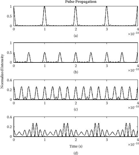
FIGURE 8.12
Pulse propagation of (a) original pulse, (b) 2× multiplication, (c) 4× multiplication, and (d) 8× multiplication with 1 nm filter bandwidth and equal lasing mode amplitude analysis.
As the multiplication factor increases, the system trajectories are moving away from the origin. As for the 4× and 8× multiplications (see Figures 8.18 to 8.21), there is neither a stable limit cycle nor a stable node on the phase planes even with the ideal multiplication parameters. Here we see the system trajectories spiral out to an outer radius and back to an inner radius again. The change in the radius of the spiral is the transient response of the system. Hence, with the increase in the multiplication factor, the system trajectories become more sophisticated. Although GVD repetition rate multiplication uses only the phase change effect in multiplication process, the inherent nonlinearities still affect its stability indirectly. Despite the reduction in the pulse amplitude, we observe uneven pulse amplitude distribution in the multiplied pulse train. The percentage of unevenness increases with the multiplication factor in the system.
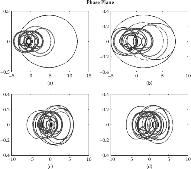
FIGURE 8.13
Phase plane of (a) original pulse, (b) 2x multiplication, (c) 4x multiplication, and (d) 8x multiplication with 1 nm filter bandwidth and equal lasing mode amplitude analysis (solid line, real part of the energy; dotted line, imaginary part of the energy; x-axes, E(t); and y-axes, E′(t)).
8.4.3 Gaussian Lasing Mode Amplitude Distribution
This set of the simulation models the practical filter used in the system. It gives us a better insight on the GVD repetition rate multiplication system behavior. The parameters used in the simulation are the same except the filter of the laser has been changed to a 1 nm (125 GHz at 1550 nm) Gaussian-profile passband filter. The spirals of the system trajectories and uneven pulse amplitude distribution are more severe than those in the uniform lasing mode amplitude analysis.
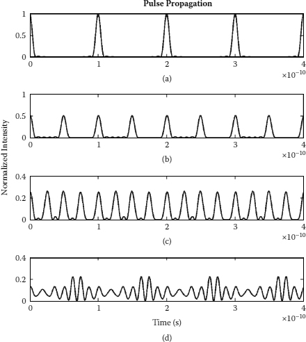
FIGURE 8.14
Pulse propagation of (a) original pulse, (b) 2x multiplication, (c) 4x multiplication, and (d) 8x multiplication with 1 nm filter bandwidth and Gaussian lasing mode amplitude analysis.
8.4.4 Effects of Filter Bandwidth
Filter bandwidth used in the mode-locked fiber ring laser will affect the system stability of the GVD repetition rate multiplication system as well. The analysis done above is based on 1 nm filter bandwidth. The number of modes locked in the laser system increases with the bandwidth of the filter used, which gives us a better quality of the mode-locked pulse train. The simulation results shown below are based on the Gaussian lasing mode amplitude distribution, 3 nm filter bandwidth used in the laser cavity, and other parameters that remain unchanged.
With wider filter bandwidth, the pulse width and the percentage pulse amplitude fluctuation decrease. This suggests a better stability condition. Instead of spiraling away from the origin, the system trajectories move inward to the stable node. However, this leads to a more complex pulse formation system.

FIGURE 8.15
Phase plane of (a) original pulse, (b) 2x multiplication, (c) 4x multiplication, and (d) 8x multiplication with 1 nm filter bandwidth and Gaussian lasing mode amplitude analysis (solid line, real part of the energy; dotted line, imaginary part of the energy; x-axes, E(t), and y-axes, E′(t)).
8.4.5 Nonlinear Effects
When the input power of the pulse train enters the nonlinear region, the GVD multiplier loses its multiplication capability as predicted. The additional nonlinear phase shift due to the high-input power is added to the total pulse phase shift and destroys the phase change condition of the lasing modes required by the multiplication condition. Furthermore, this additional nonlinear phase shift changes the pulse shape and the phase plane of the multiplied pulses.
8.4.6 Noise Effects
The above simulations are all based on the noiseless situation. However, in the practical optical communication systems, noises are always sources of nuisance that can cause system instability; therefore, it must be taken into consideration for system stability studies.

FIGURE 8.16
Pulse propagation of (a) original pulse, (b) 2x multiplication, (c) 4x multiplication, and (d) 8x multiplication with 3 nm filter bandwidth and Gaussian lasing mode amplitude analysis.
Because the optical intensity of the m-times multiplied pulse is m-times less than the original pulse, it is more vulnerable to noise. The signal is difficult to differentiate from the noise within the system if the power of the multiplied pulse is too small. The phase plane of the multiplied pulse is distorted due to the presence of the noise, which leads to poor stability performance.
8.4.7 Demonstration
The obtained 10 GHz output pulse train from the mode-locked fiber ring laser is shown in Figure 8.22. Its spectrum is shown in Figure 8.23. This output was then used as the input to the dispersion compensating fiber, which acts as the GVD multiplier in our experiment. The obtained 4× multiplication by the GVD effect and its spectrum are shown in Figures 8.24 and Figure 8.25. The spectra for both cases (original and multiplied pulse) are the same because this repetition rate multiplication technique utilizes only the change of phase relationship between lasing modes and does not use the fiber’s nonlinearity.
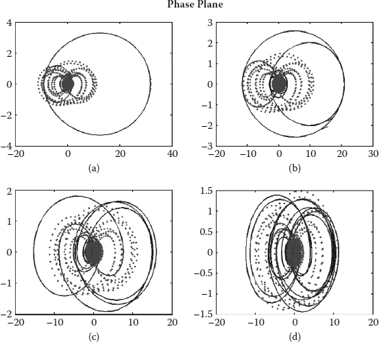
FIGURE 8.17
Phase plane of (a) original pulse, (b) 2x multiplication, (c) 4x multiplication, and (d) 8x multiplication with 3 nm filter bandwidth and Gaussian lasing mode amplitude analysis (solid line, real part of the energy; dotted line, imaginary part of the energy; x-axes, E(t); and y-axes, E′(t)).
The multiplied pulse suffers an amplitude reduction in the output pulse train; however, the pulse characteristics should remain the same. The instability of the multiplied pulse train is mainly due to the slight deviation from the required DCF length (0.2% deviation). Another reason for the pulse instability, which derived from our analysis, is the divergence of the pulse energy variation in the vicinity around the origin, as the multiplication factor gets higher. The pulse amplitude decreases with the increase in, multiplication factor, as the fact of energy conservation; when it reaches a certain energy level, which is indistinguishable from the noise level in the system, the whole system will become unstable and noisy.

FIGURE 8.18
Pulse propagation of (a) original pulse, (b) 2x multiplication, (c) 4x multiplication, and (d) 8x multiplication with 3 nm filter bandwidth, Gaussian lasing mode amplitude analysis and input power = 1 W.
8.4.8 Remarks
In this section, 4× repetition rate multiplication by using the fiber GVD effect is demonstrated; hence, a 40 GHz pulse train can be obtained from 10 GHz mode-locked fiber laser source. However, its stability is of great concern for practical use in optical communications systems. Although the GVD repetition rate multiplication technique is linear in nature, the inherent nonlinear effects in such a system may disturb the stability of the system. Hence, any linear approach may not be suitable in deriving the system stability. Stability analysis for this multiplied pulse train has been studied by using the nonlinear control stability theory, which is the first time, to the best of our knowledge, that phase plane analysis is being used to study the transient and stability performance of the GVD repetition rate multiplication system. Surprisingly, from the analysis model, the stability of the multiplied pulse train can hardly be achieved even under perfect multiplication conditions. Furthermore, we observed uneven pulse amplitude distribution in the GVD multiplied pulse train, which is due to the energy variations between the pulses that cause some energy beating between them. Another possibility is the divergence of the pulse energy variation in the vicinity around the equilibrium point that leads to instability.

FIGURE 8.19
Phase plane of (a) original pulse, (b) 2x multiplication, (c) 4x multiplication, and (d) 8x multiplication with 3 nm filter bandwidth, Gaussian lasing mode amplitude analysis and input power = 1 W (solid line, real part of the energy; dotted line, imaginary part of the energy; x-axes, E(t); and y-axes, E′(t)).

FIGURE 8.20
Pulse propagation of (a) original pulse, (b) 2x multiplication, (c) 4x multiplication, and (d) 8x multiplication with 3 nm filter bandwidth, Gaussian lasing mode amplitude analysis, and 0 dB signal-to-noise ratio.
The pulse amplitude fluctuation increases with the multiplication factor. Also, with the wider filter bandwidth used in the laser cavity, better stability conditions can be achieved. The nonlinear phase shift and noises in the system challenge the system stability of the multiplied pulses. They not only change the pulse shape of the multiplied pulses, they also distort the phase plane of the system. Hence, the system stability is greatly affected by the self-phase modulation as well as the system noises.
This stability analysis model can further be extended to include some system nonlinearities, such as the gain saturation effect, nonquadrature biasing of the modulator, fiber nonlinearities, and so forth. The chaotic behavior of the system may also be studied by applying different initial phase and injected energy conditions to the model.

FIGURE 8.21
Phase plane of (a) original pulse, (b) 2x multiplication, (c) 4x multiplication, and (d) 8x multiplication with 3 nm filter bandwidth, Gaussian lasing mode amplitude analysis, and 0 dB signal-to-noise ratio (solid line, real part of the energy; dotted line, imaginary part of the energy; x-axes, E(t); and y-axes, E’(t)).
![]()
8.5 Conclusions
We have successfully demonstrated a mode-locked laser operating under the open-loop condition and with optical to electrical (O/E) RF feedback providing regenerative mode locking. The O/E feedback can certainly provide a self-locking mechanism under the condition that the polarization characteristics of the ring laser are manageable. The regenerative MLFRL can self-lock even under the DC drifting effect of the modulator bias voltage (over 20 hours)*. The generated pulse trains of 4.5 ps duration can be, with minimum difficulty, compressed further to less than 3 ps for 160 Gb/s optical communication systems.

FIGURE 8.22
10 GHz pulse train from mode-locked fiber ring laser (100 ps/div, 50 mV/div).
We also demonstrated 660th and 1230th orders of rational harmonic mode locking from a base modulation frequency of 100 MHz in the optically amplified fiber ring laser, hence achieving 66 GHz and 123 GHz pulse repetition frequency. Besides the repetition rate multiplication, we obtained a high pulse compression factor in the system, ~35× and 40× relative to the nonmultiplied laser system. In addition, we use phase plane analysis to study the laser system behavior. From the analysis model, the amplitude stability of the detuned pulse train can only be achieved under negligible or no harmonic distortion condition, which is the ideal situation. The phase plane analysis also reveals the pulse-forming complexity of the laser system.

FIGURE 8.23
10 GHz pulse spectrum from mode-locked fiber ring laser.

FIGURE 8.24
40 GHz multiplied pulse train (20 ps/div, 1 mV/div).
Furthermore, the N-times, multiplication of the repetition rate can be achieved by using the fiber, GVD effect, which is a linear diffraction mechanism; hence, a 40 GHz pulse train is obtained from a 10 GHz mode-locked fiber laser source. Stability analysis for this multiplied pulse train has been studied by using the nonlinear control stability theory in which a phase plane analysis is being used to study the transient and stability performance of the GVD repetition rate multiplication system. Surprisingly, from the analysis model, the stability of the multiplied pulse train can hardly be achieved even under perfect multiplication conditions. Furthermore, we observed uneven pulse amplitude distribution in the GVD multiplied pulse train, which is due to the energy variations between the pulses that cause some energy beating between them. Another possibility is the divergence of the pulse energy variation in the vicinity around the equilibrium point that leads to instability.
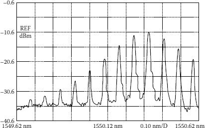
FIGURE 8.25
40 GHz pulse spectrum from group velocity dispersion multiplier.
The pulse amplitude fluctuation increases with the multiplication factor. Furthermore, with wider filter bandwidth used in the laser cavity, better stability condition can be achieved. The nonlinear phase shift and noises in the system challenge the system stability of the multiplied pulses. They not only change the pulse shape of the multiplied pulses, they also distort the phase plane of the system. Hence, the system stability is greatly affected by the self-phase modulation as well as the system noises. This stability analysis model can be extended to include some system nonlinearities, such as the gain saturation effect, nonquadrature biasing of the modulator, fiber nonlinearities, and so forth. The chaotic behavior of the system may also be studied by applying different initial phase and injected energy conditions to the model.
Currently the design and demonstration of multiwavelength mode-locked lasers to generate ultrashort and ultrahigh repetition-rate pulse sequences are under consideration by employing a multispectral filter demultiplexer and multiplexer incorporated within the fiber ring. Furthermore, the locking in the THz region will also be reported. The principal challenge is the conversion from the THz photonic to electronic domain for stabilization. This can be implemented in either electronic or photonic sampling.
![]()
References
1. K. Kuroda and H. Takakura, Mode-Locked Ring Laser with Output Pulse Width of 0.4 ps, IEEE Trans. Inst. Meas., 48, 1018–1022, 1999.
2. G. Zhu, H. Chen, and N. Dutta, Time Domain Analysis of a Rational Harmonic Mode-Locked Ring Fiber Laser, J. Appl. Phys., 90, 2143–2147, 2001.
3. C. Wu and N.K. Dutta, High Repetition Rate Optical Pulse Generation Using a Rational Harmonic Mode-Locked Fiber Laser, IEEE J. Quantum Electron., 36, 145–150, 2000.
4. K. K. Gupta, N. Onodera, and M. Hyodo, Technique to Generate Equal Amplitude, Higher-Order Optical Pulses in Rational Harmonically Mode Locked Fiber Ring Lasers, Electron. Lett., 37, 948–950, 2001.
5. Y. Shiquan, L. Zhaohui, Z. Chunliu, D. Xiaoyi, Y. Shuzhong, K. Guiyun, and Z. Qida, Pulse-Amplitude Equalization in a Rational Harmonic Mode-Locked Fiber Ring Laser by Using Modulator as Both Mode Locker and Equalizer, IEEE Photonics Technol. Lett., 15, 389–391, 2003.
6. J. Azana and M.A. Muriel, Technique for Multiplying the Repetition Rates of Periodic Trains of Pulses by Means of a Temporal Self-Imaging Effect in Chirped Fiber Gratings, Opt. Lett., 24, 1672–1674, 1999.
7. S. Atkins and B. Fischer, All Optical Pulse Rate Multiplication Using Fractional Talbot Effect and Field-to-Intensity Conversion with Cross Gain Modulation, IEEE Photonics Technol. Lett., 15, 132–134, 2003.
8. J. Azana and M. A. Muriel, Temporal Self-Imaging Effects: Theory and Application for Multiplying Pulse Repetition Rates, IEEE J. Quantum Electron., 7, 728–744, 2001.
9. D. A. Chestnut, C. J. S. de Matos, and J. R. Taylor, 4× Repetition Rate Multiplication and Raman Compression of Pulses in the Same Optical Fiber, Opt. Lett., 27, 1262–1264, 2002.
10. S. Arahira, S. Kutsuzawa, Y. Matsui, D. Kunimatsu, and Y. Ogawa, Repetition Frequency Multiplication of Mode-Locked Using Fiber Dispersion, J. Lightwave Technol., 16, 405–410, 1998.
11. W. J. Lai, P. Shum, and L. N. Binh, Stability and Transient Analyses of Temporal Talbot-Effect-Based Repetition-Rate Multiplication Mode-Locked Laser Systems, IEEE Photonics Technol. Lett., 16, 437–439, 2004.
12. K. K. Gupta, N. Onodera, K. S. Abedin, and M. Hyodo, Pulse Repetition Frequency Multiplication via Intracavity Optical Filtering in AM Mode-Locked Fiber Ring Lasers, IEEE Photonics Technol. Lett., 14, 284–286, 2002.
13. K. S. Abedin, N. Onodera, and M. Hyodo, Repetition-Rate Multiplication in Actively Mode-Locked Fiber Lasers by Higher-Order FM Mode-Locking Using a High Finesse Fabry Perot Filter, Appl. Phys. Lett., 73, 1311–1313, 1998.
14. K. S. Abedin, N. Onodera, and M. Hyodo, Higher Order FM Mode-Locking for Pulse-Repetition-Rate Enhancement in Actively Mode-locked Lasers: Theory and Experiment, IEEE J. Quantum Electron., 35, 875–890, 1999.
15. W. Daoping, Z. Yucheng, L. Tangjun, and J. Shuisheng, 20 Gb/s Optical Time Division Multiplexing Signal Generation by Fiber Coupler Loop-Connecting Configuration, presented at Fourth Optoelectronics and Communications Conference, 1999.
16. D. L. A. Seixasn and M. C. R. Carvalho, 50 GHz Fiber Ring Laser Using Rational Harmonic Mode-Locking, presented at Microwave and Optoelectronics Conference, Nis, Yugoslav, 2001.
17. R. Y. Kim, Fiber Lasers and Their Applications, presented at Laser and Electro-Optics, CLEO/Pacific Rim ’95, Jeju, Korea, 1995.
18. H. Zmuda, R. A. Soref, P. Payson, S. Johns, and E. N. Toughlian, Photonic Beamformer for Phased Array Antennas Using a Fiber Grating Prism, IEEE Photonics Technol. Lett., 9, 241–243, 1997.
19. G. A. Ball, W. W. Morey, and W. H. Glenn, Standing-Wave Monomode Erbium Fiber Laser, IEEE Photonics Technol. Lett., 3, 613–615, 1991.
20. D. Wei, T. Li, Y. Zhao, et al., Multi-Wavelength Erbium-Doped Fiber Ring Laser with Overlap-Written Fiber Bragg Gratings, Opt. Lett., 25, 1150–1152, 2000.
21. S. K. Kim, M. J. Chu, and J. H. Lee, Wideband Multi-Wavelength Erbium-Doped Fiber Ring Laser with Frequency Shifted Feedback, Opt. Commun., 190, 291–302, 2001.
22. Z. Li, L. Caiyun, and G. Yizhi, A Polarization Controlled Multi-Wavelength Er-Doped Fiber Laser, presented at APCC/OECC99, Wuhan, China 1999.
23. R. M. Sova, C. S. Kim, and J. U. Kang, Tunable Dual-Wavelength All-PM Fiber Ring Laser, IEEE Photonics Technol. Lett., 14, 287–289, 2002.
24. I. D. Miller, D. B. Mortimore, P. Urquhart, et al., A Nd3+-Doped CW Fiber Laser Using All-Fiber Reflectors, Appl. Opt., 26, 2197–2201, 1987.
25. X. Fang and R. O. Claus, Polarization-Independent All-Fiber Wavelength-Division Multiplexer Based on a Sagnac Interferometer, Opt. Lett., 20, 2146–2148, 1995.
26. X. Fang, H. Ji, C. T. Aleen, et al., A Compound High-Order Polarization-Independent Birefringence Filter, IEEE Photonics Technol. Lett., 19, 458–460, 1997.
27. X. P. Dong, Li, S., K. S. Chiang et al., Multi-Wavelength Erbium-Doped Fiber Laser Based on a High-Birefringence Fiber Loop, Electron. Lett., 36, 1609–1610, 2000.
28. D. Jones, H. Haus, and E. Ippen, Subpicosecond Solitons in an Actively Mode Locked Fiber Laser, Opt. Lett., 21(22), 1818–1820, 1996.
29. X. Zhang, M. Karlson, and P. Andrekson, Design Guideline for Actively Mode Locked Fiber Ring Lasers, IEEE Photonics Tech. Lett., 1103–1105, 1998.
30. A. E. Siegman, Laser. University Press, Mill Valley, CA, 1986.
31. J. J. E. Slotine and W. Li, Applied Nonlinear Control. Prentice Hall, Englewood Cliffs, NJ, 1991.
* Typically the DC bias voltage of a LiNbO3 intensity modulator is drifted by 1.5 volts after 15 hours of continuous operation.