
![]()
Appendix C: Simulink® Models
![]()
C.1 MATLAB ® and Simulink ® Modeling Platforms
A modeling and simulation platform for optical fiber transmission systems has been developed using MATLAB and Simulink, an environment for simulation and model-based design [1]. There are some advantages of the Simulink modeling platform:
• Subsystem blocks for a complicated transmission system can be set up from the basic blocks available in the toolboxes and block-sets of Simulink. It is noted that there are no block-sets for optical communication in Simulink. Therefore, the main functional blocks of the optical communication system in the Simulink platform have been developed for years. Details of operational principles as well as examples of the optical components and transmission systems can be found in Binh [1].
• Signals can be easily monitored at any point along the simulation system by available scopes in Simulink block-sets.
• Numerical data can be stored for postprocessing in MATLAB to estimate the performance of the system.
An example of an optical fiber transmission system is shown in Figure C.1. Depending on different problems or targets, various Simulink models are set up for investigation in this thesis.
![]()
C.2 Wavelength Converter in Wavelength-Division Multiplexing System
See Figures C.2 and C.3.

FIGURE C.1
An example of an optical fiber transmission system consisting of main blocks: optical transmitter, fiber transmission link, and optical receiver.
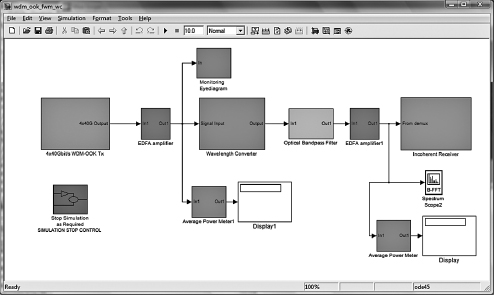
FIGURE C.2
The Simulink model of optical parametric amplifier used as a wavelength converter in the wavelength-division multiplexing system.
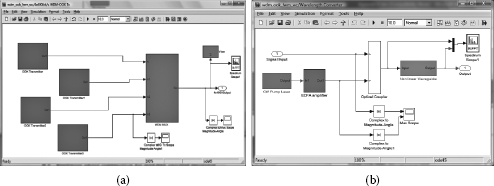
FIGURE C.3
(a) Simulink model of wavelength-division multiplexing (WDM) transmitter consisting of four optical transmitters at different wavelengths and a wavelength multiplexer. (b) Simulink setup of the parametric amplifier using the model of nonlinear waveguide used for wavelength conversion in a WDM system.
![]()
C.3 Nonlinear Phase Conjugation for Mid-link Spectral Inversion
See Figures C.4 through C.7.

FIGURE C.4
Simulink setup of a long-haul 40 Gbit/s transmission system using nonlinear phase conjugation for distortion compensation.

FIGURE C.5
(a) Simulink model of an intensity optical modulator driven by data. (b) Simulink model of an optical pulse carver driven by a sinusoidal signal for RZ pulse generation.

FIGURE C.6
(a) Simulink model of an optical transmitter for RZ-OOK modulation scheme. (b) Simulink model of an optical receiver for on-off keying signal.
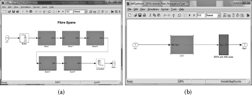
FIGURE C.7
(a) Simulink model of each fiber transmission section consisting of 5 spans. (b) Simulink model of each span consisting of one single-mode fiber and one erbium-doped fiber amplifier for loss compensation.

FIGURE C.8
Simulink setup of a short pulse generator at 40 GHz based on the parametric amplifier.
![]()
C.4 Pulse Generator
See Figures C.8 and C.9.

FIGURE C.9
Simulink blocks inside the 40 GHz short-pulse generator to demonstrate ultra-high-speed switching based on parametric amplification.

FIGURE C.10
Simulink setup of the 160 Gbit/s optical time-division multiplexing system using four-wave mixing process for demultiplexing.
![]()
C.5 Optical Time-Division Multiplexing (OTDM) Demultiplexer
For the OTDM system using an on-off keying (OOK) scheme, the Simulink models of the transmitter and receiver are similar to those shown in Figure C.6 with using a mode-locked fiber laser (MLFL) instead of a carver. Figure C.12 shows the Simulink models of the transmitter and receiver in the OTDM system using the differential quadrature phase shift keying (DQPSK) modulation scheme. (See Figures C.10 through C.13.)
![]()
C.6 Triple Correlation
Figure C.14 shows the Simulink model for the triple correlation based on four-wave mixing (FWM) in the nonlinear waveguide. The structural block consists of two variable delay lines to generate delayed versions of the original signal as shown in Figure C.15 and frequency converters to convert the signal into three different waves before combining at the optical coupler to launch into the nonlinear waveguide. (See Figures C.14 through C.18.)
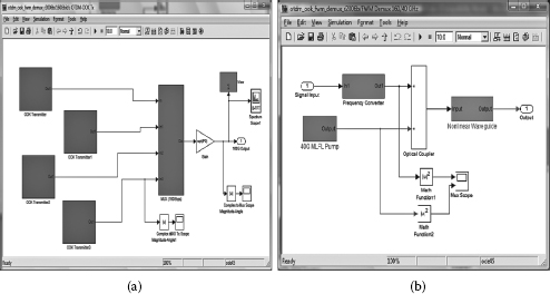
FIGURE C.11
(a) Simulink model of optical time-division multiplexing (OTDM) transmitter consisting of four optical transmitters and an OTDM multiplexer. (b) Simulink model of the four-wave mixing (FWM)-based demultiplexer.

FIGURE C.12
(a) Simulink model of an optical transmitter for differential quadrature phase shift keying (DQPSK) modulation scheme. (b) Simulink model of an optical balanced receiver for DQPSK signal.

FIGURE C.13
Time traces of (a) the 160 Gbit/s optical time-division multiplexing signal, (b) the control signal, and (c) the 40 Gbit/s demultiplexed signal.

FIGURE C.14
Simulink setup for investigation of the triple correlation based on the four-wave mixing process.

FIGURE C.15
(a) Simulink setup of the four-wave mixing (FWM)-based triple-product generation. (b) Simulink setup of the theory-based triple-product generation.

FIGURE C.16
The variation in time domain of the time delay variable, the original signal, and the delayed signal.

FIGURE C.17
(a) Spectrum with equal wavelength spacing at the output of the nonlinear waveguide. (b) Spectrum with unequal wavelength spacing at the output of the nonlinear waveguide.
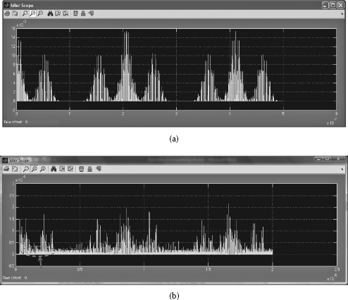
FIGURE C.18
Generated triple-product waves in time domain of the dual-pulse signal based on (a) theory and (b) four-wave mixing in a nonlinear waveguide.
![]()
Reference
1. L. N. Binh, Optical Fiber Communications Systems: Theory and Practice with MATLAB® and Simulink® Models, CRC Press, Boca Raton, FL, 2010.