22 3. TILTING VEHICLE DYNAMICS
3.4 SUSPENSION DESIGNS FOR NTV STABILITY
Among the three major tilting mechanisms reviewed in Chapter 2, the suspension tilting sys-
tem has a great potential to be adopted for NTVs due to their compact size and re-use of the
suspension mechanism which helps to reduce system weight and cost. However, generating
pure asynchronous motions of the suspension mechanism along with wheel assemblies are more
complicated than visualized in Figure 2.4. Due to manufacturing and maintenance difficulties, a
guide-rail structure allowing wheel assemblies to move along its rail (a.k.a. sliding pillar mecha-
nism [48]) is rarely seen on modern automobiles. Instead, various suspension mechanisms have
been proposed which introduce lateral and longitudinal wheel motions as the suspension struts
are driven for tilting. When suspension motions are relatively large for NTVs during harsh cor-
nering, the impact of suspension kinematics on dynamical behavior is no loner negligible. In this
section, a trailing-arm mechanism is adopted as an example for the analysis, and the demon-
strated procedure can be implemented on suspension mechanisms for similar NTV applications.
3.4.1 ROLL ANGLE ANALYSIS
is subsection focuses on the kinematics perspectives of additional roll angle changes consider-
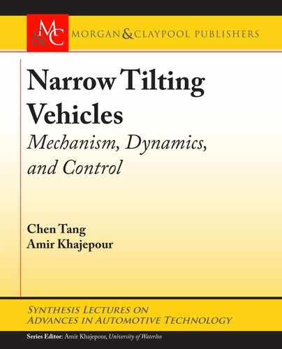
ing the suspension mechanism during tilting. A tadpole-configured NTV with the trailing arm
mechanism is adopted, as shown in Figure 3.3.
Instead of analyzing the vehicle in a tilted position, it would be much easier to visualize
and study NTV kinematics with its cabin in an upright pose and a “rotating” ground plane. e
plane can be constructed, for any cabin pose, using contact points at three wheels. By comparing
the angle between normal vectors of the new contact plane with the original (un-tilted) one, the
vehicle rotation as a consequence of suspension movements can then be analyzed [24].
e original ground plane OXYZ is adopted as the global coordinate system with OZ point-
ing upward. e un-tilted pose of the NTV can be defined with OXZ be the symmetrical plane
of the vehicle; OX pointing forward; and OZ across the CoG of the vehicle. e contact points
are assumed to be located at the bottom of wheels. Points A, B, C denote the nominal contact
points at front-left, front-right, and rear wheels for the un-tilted pose, while A
0
, B
0
, C
0
denotes
their new positions after enforcing suspension movements for tilting. e normal directions of
the original and new ground planes are denoted as On
1
0 0 1
T
and On
2
accordingly.
Given the nominal track width at front axle T
w0
, and axle to CG distances (a; b), position
vectors for the original contact points A, B, C are

3.4. SUSPENSION DESIGNS FOR NTV STABILITY 23
b
B’
A’
Y
Z
X
O
n
n
∆Z
∆Z
a
+
∆X
a
+
∆
X
C(C’)
Figure 3.3: Kinematic analysis of NTV with trailing arm mechanisms [24]. (Image used with
permission.)
!
OA D
a C
T
w0
2
0
T
!
OB D
a
T
w0
2
0
T
!
OC D
b 0 0
T
:
(3.16)
For a general tilting scenario, z
1
and z
2
are applied, respectively, as the vertical dis-
placements of the two front wheels. Since the wheels are constrained by the trailing arm mech-
anism, no lateral displacement is produced, but both wheels move x
1
and x
2
, respectively,
in the longitudinal direction. e global position vectors of the new contact points A
0
, B
0
, C
0
are written as
!
OA
0
D
!
OA C
x
1
0 z
1
T
!
OB
0
D
!
OB C
x
2
0 z
2
T
!
OC
0
D
!
OC:
(3.17)

24 3. TILTING VEHICLE DYNAMICS
Computational geometry approach could be adopted to solve the normal vector of the
new ground plane On
2
as
On
2
D
!
C
0
B
0
!
C
0
A
0
!
j
C
0
B
0
j
!
j
C
0
A
0
j
D
1
q
n
2
21
C n
2
22
C n
2
23
2
6
6
4
n
21
n
22
n
23
3
7
7
5
; (3.18)
where n
21
; n
22
; n
23
are the components of the cross product
!
C
0
B
0
!
C
0
A
0
. From position vec-
tors solved from Eqs. (3.16) and (3.17), this leads to
n
21
D
T
w0
2
.
z
1
C z
2
/
n
22
D
.
a C b C x
2
/
z
1
C
.
a C b C x
1
/
z
2
n
23
D
T
w0
2
.
2a C 2b C x
1
C x
2
/
:
Rotational motion () of the NTV, with the proposed “rotation ground” formulation, can
be determined by the angle between normal vectors On
1
and On
2
as
D arccos
.
On
1
On
2
/
D arctan
s
n
2
21
C n
2
22
n
2
23
!
: (3.19)
e instantaneous rotation axis Oe
r
is found by the cross product of normal vectors as
Oe
r
D On
2
On
1
D
1
q
n
2
21
C n
2
22
C n
2
23
2
4
n
22
n
21
0
3
5
: (3.20)
It is shown in Eq. (3.20) that the rotation axis has zero component in the global coordinate
system, which indicates no yaw motion can be generated by arbitrary movements of trailing
arm suspensions [24]. e projected rotation along OX and OY directions can be interpreted
as the tilting and pitch motion, respectively. To eliminate the undesired pitch, the term n
21
in
Eq. (3.20) has to be zero, which leads to
z
1
C z
2
D 0: (3.21)
It is suggested in Eq. (3.21) that, for trailing arm mechanisms to generate a pure tilting
motion without introducing pitch, asynchronous motions (same magnitudes but reverse direc-
tions) of wheel modules in the vertical direction are desired. is agrees with the intuition that
any synchronous wheel movement will lift the front axle and end up with pitch motion of the
full vehicle.
Imposing this condition in the rotation angle solved from Eq. (3.19) leads to a simplified
pure tilting angle
x
as
..................Content has been hidden....................
You can't read the all page of ebook, please click here login for view all page.