
18 3. TILTING VEHICLE DYNAMICS
where
F
xij max
D
x
F
zij
F
yij max
D
y
F
zij
and
x
;
y
are the friction coefficients in longitudinal and lateral directions, respectively.
3.2 ROLL DYNAMICS AND ROLLOVER INDEX
Roll dynamics is crucial to the operational safety of any NTVs. is section derives a vehicle
roll model considering active tilting actuators. Apart from that, as a measure of the rollover
tendency, a rollover index based on lateral load transfer (LTR) is also developed.
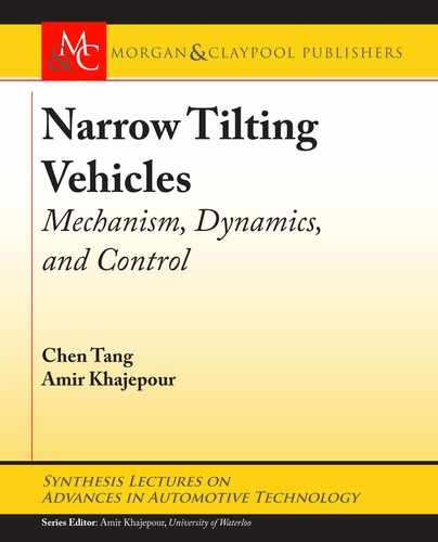
A generic vehicle roll model is adopted and illustrated in Figure 3.2. e suspension system
is approximated using an equivalent rotational spring .K
/ and damper .C
/ connecting the
sprung .m
s
/ and un-sprung mass .m
u
/ at vehicle roll center (RC). e lateral acceleration .a
y
/
is treated as a disturbance to the roll model, and the tilting actuator generates an active control
moment .T
x
/ to regulate vehicle roll motions. e net forces at left- and right-side wheels are
written as .F
zl
; F
zr
/ and .F
yl
; F
yr
/, respectively, for their vertical and lateral components.
Geometrical parameters like the distance between sprung mass CoG to roll center .h
s
/, CoG
height of the un-sprung mass .h
u
/, roll center height .h
rc
/, and track width .T
w
/ are illustrated
in the figure.
e roll dynamics equation can then be derived as,
R
D
1
I
x
T
x
m
s
h
s
cos
.
/
mI
x
a
y
K
m
s
gh
s
sin./
I
x
C
I
x
P
; (3.8)
where I
x
denotes the roll inertia of the vehicle.
By defining the roll rate and roll angle as the states
ŒX
r
D
P
T
, tilting mo-
ment as the control input .U
r
D
Œ
T
x
/, and maneuver-induced lateral acceleration as distur-
bances .W
r
D
a
y
/, roll dynamics in Eq. (3.8) under the small angle assumption can be written
in the state-space form as
P
X
r
D A
r
X
r
C B
r
U
r
C E
r
W
r
; (3.9)
where
A
r
D
"
C
I
x
m
s
gh
s
K
I
x
1 0
#
; B
r
D
"
1
I
x
0
#
; E
r
D
"
m
s
h
s
I
x
0
#
:
For the rollover mitigation control, LTR index [41, 42] is widely adopted as the evaluation
metric for vehicle rollover tendency. Compared with the SSF index discussed in Section 1.2
which considers only geometrical aspects, the LTR is a more proper index to quantify the vehicle

3.2. ROLL DYNAMICS AND ROLLOVER INDEX 19
y
z
φ
RC
K
φ
C
φ
m
u
a
y
m
u
g
m
u
a
y
m
s
a
y
m
s
a
y
m
u
g
m
s
g
m
s
g
F
yl
F
zl
F
zr
F
yr
F
yr
F
zr
F
zl
F
yl
T
w
T
x
T
x
T
x
K
φ
φ+C
φ
φ̇
K
φ
φ+C
φ
φ̇
h
RC
h
u
h
s
Figure 3.2: Vehicle roll model for NTV.
dynamical stability under active tilting control. By definition [43], LTR can be written by vertical
tire forces as
LTR
D
F
zl
F
zr
F
zl
C F
zr
: (3.10)
Intuitively, the vehicle rollover can be defined as a situation when one of the wheels lifts
off the ground. In other words, it happens when the vertical load on any of the wheels drops
to zero. According to the definitions in Eq. (3.10), LTR index could vary from Œ1; 1. For an
ideally balanced vehicle with no lateral load transfer, LTR D 0.
Since vertical tire forces are not directly measurable on mass-produced vehicles, it is de-
sirable to rewrite the LTR index in terms of measurable parameters and states for control pur-
poses [44, 45]. From the roll model derived in Eq. (3.9), the normal load difference can be
written as
F
zl
F
zr
D
2
T
w
I
x
R
C m
u
h
u
a
y
C m
s
h
0
s
a
y
m
s
gh
s
; (3.11)
where h
0
s
D h
s
C h
rc
is the CoG height of the sprung mass.
..................Content has been hidden....................
You can't read the all page of ebook, please click here login for view all page.