
Hour 10. Basic Rigging: Preparing Objects for Animation
What You’ll Learn in This Hour:
![]() What a rig is and what should be rigged
What a rig is and what should be rigged
![]() How to prepare an object to be rigged
How to prepare an object to be rigged
![]() How to create a simple hierarchy
How to create a simple hierarchy
![]() What a rig’s functionality should be
What a rig’s functionality should be
The objects that you’ve modeled so far have been at their very simplest polygonal and NURBS objects—basically, shape nodes contained in a transform node. Remember that a transform node is almost like an invisible box that holds the geometry and moves it around in space. For the purposes of animating objects, we have to create at the very least a simple hierarchy, and at most a fully deforming rig.
Caution: Setting the Project Before Starting
When we start working with rigs, no matter how simple they are, it is important to set your Maya project correctly. Without properly setting your project, you may run into many problems later referencing your files. Set your project to this Hour’s files by going to File, Set Project... and then choose the folder where you’ve saved this Hour’s files.
In this hour, you find out how to correctly set up an object with a simple rig. It will contain some interesting features even though it is still very basic. The most important thing to learn from this Hour is the steps you must take to make sure an object is ready for animation. Quite often, CG artists get lazy by the end of a project and just import geometry and try to move it around. This can lead to many headaches and having to redo work. Let’s learn to avoid these problems.
What Is a Rig?
A rig is a control and deformation system created from curves, joints, groups, and other nodes to give animators the tools they need to create the movement desired. A rig is a complete system that contains all of the functionality that object will require. For instance, a very common rig is a “bouncing ball” rig. This rig needs to have movement controls for the ball mesh, squash, and stretch controls so that when the ball bounces, it looks realistic, rotation controls that allow the ball to roll along the ground, and perhaps even some extra added deformation controls so that an animator can make the ball look like it is performing anthropomorphized actions (looking, breathing, and so on). The most common rigs use NURBS curves exclusively for their controls systems. We will be looking at basic rigging principles in this Hour, and next Hour we’ll rig the character we modeled in Hour 8, “Character Modeling.”
Note: Environment Objects vs. Props
Not everything needs a rig to be used in a scene. You do not have to rig objects that are unmoving or are placed once in an environment. For instance, it is probably a good idea to have a chandelier model be separate from a living room model so you can work on them separately, and neither needs a rig if you are just going to be placing the chandelier in position when it’s done. However, if a character in the scene is going to swing from the chandelier, now you need a rig for it as well.
Why We Rig
The most basic question about the necessity of creating rigs even for simple objects has many answers. Here are a few:
![]() Creating a rig for an object allows you to give an animator greater control over how the object moves.
Creating a rig for an object allows you to give an animator greater control over how the object moves.
![]() Creating a rig commonly entails adding extra deformation to an object, giving animators the ability to manipulate the geometry.
Creating a rig commonly entails adding extra deformation to an object, giving animators the ability to manipulate the geometry.
![]() Using a rig with common naming conventions allows for animation to be copied or retained from scene to scene.
Using a rig with common naming conventions allows for animation to be copied or retained from scene to scene.
![]() Geometry can be added or subtracted from a good rig, making it so that the modeling and the rigging can frequently occur at the same time by different artists.
Geometry can be added or subtracted from a good rig, making it so that the modeling and the rigging can frequently occur at the same time by different artists.
![]() In order to create some complex systems such as constraints in the animation scene, it is necessary for an object to have more than one point of control, so we add them as we rig.
In order to create some complex systems such as constraints in the animation scene, it is necessary for an object to have more than one point of control, so we add them as we rig.
![]() Having one set rig for an object means that you do not have to redo work each time you start a new animation scene.
Having one set rig for an object means that you do not have to redo work each time you start a new animation scene.
![]() Rigging an object signifies it is ready to be animated.
Rigging an object signifies it is ready to be animated.
There are some other reasons, but these are the most common and important reasons to create rigs for objects you want to move and deform. Sure, you can add deformations in your animation files later, but you wouldn’t want to re-create all of the controls on an object each time you want to animate it.
Preparing Your Mesh
The first thing we need to do is prepare the mesh to be rigged. Open hammer_Prep.ma in this Hour’s folder. Frame the hammer in the Persp panel and change to the Persp/Outliner saved layout, like in Figure 10.1.

FIGURE 10.1 The Outliner is an essential window for creating rigs, because it shows the scene objects in hierarchy format.
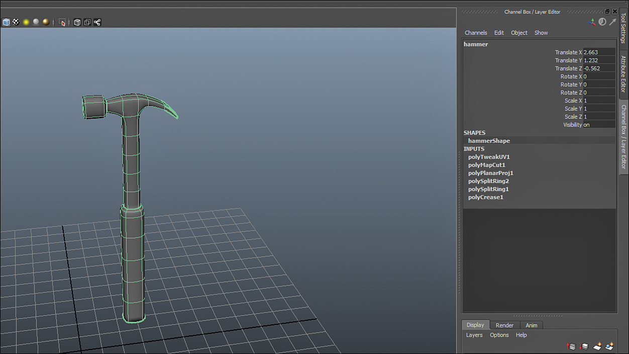
Now select the hammer model. In the Channel Box, you will see some history and some transformations on the model, like in Figure 10.2.
Delete the history by going to Edit, Delete by Type, History, or by pressing Ctrl+Shift+D. Before we remove the transformations on the model, we should center its pivot. The advantage to centering the pivot of an object is that the transform handles always center themselves at the pivot, which is more convenient. Because we are not going to ever animate the hammer model directly anymore (only using the controls we will set up now), the fact that an object also rotates and scales from its pivot doesn’t affect the hammer. However, we will be making sure pivots are where we want them to be for our controls as we build our rig. Center the pivot of the hammer by going to Modify, Center Pivot. The pivot snaps to the average center of the vertices in the object. It should be in the middle of the handle of the hammer, as shown in Figure 10.3.

Now let’s place the object at the world origin. Select the hammer, switch to the Move tool, and while holding down the X key (default for snapping to grid line), MMB drag the hammer to the center line in the grid, like in Figure 10.4.

FIGURE 10.4 The hammer has been moved to the world origin. This is helpful because now at a glance we can see if the hammer has transformations on it or not, which is essential for proper rigging.
This is important because we always want a value of 0,0,0 for the position of an object and a scale of 1. Objects that are scaled and transformed within a rig are considered messy and can misbehave when we try to animate or apply constraints to them. We now remove transformations by clicking on Modify, Freeze Transformations. After that is done, the Channel Box should have no transformations showing, as in Figure 10.5.

FIGURE 10.5 The channels are all zeroed, signifying the hammer now has its origin at the world origin. Again, this is all good workflow for rigging.
The steps we’ve taken to conform the mesh to a good start for rigging are the minimum that may be required. There may be multiple errors in the model itself—from flipped normal, open edges, and multiple faces on top of each other, to name a few. The steps to center the pivot, remove transformations, and return an object to the world origin should be done after you are sure your mesh doesn’t contain any other errors. The hammer model we are using is free from errors. To see if your model is suffering from some of the errors I mentioned, you can switch to the Polygons menu set by pressing F3 and clicking on Mesh, Cleanup.... This tool will diagnose your mesh, but know that there are many errors beyond what this tool can diagnose. Maya gives you immense freedom and power when creating objects, but that comes with the possibility to create some messy geometry. Work methodically and carefully to avoid most problems.
Simple Hierarchy
Now that the mesh is conformed, we are ready to build some controls into it. Notice in the Outliner that the hammer doesn’t have any hierarchy; it exists in world space on its own. Figure 10.6 shows the Outliner of our scene and the lone hammer mesh like I described.

A good prop rig starts with creating a few nested groups. This simple hierarchy is in place to separate the geometry and the control system of a rig. Follow the next few steps to get this hierarchy started:
![]() Select the hammer and press Ctrl+G.
Select the hammer and press Ctrl+G.
![]() This creates a group holding the hammer.
This creates a group holding the hammer.
![]() Rename the group to hammer_Geo_GRP by double-clicking on the name in the Outliner or in the Channel Box.
Rename the group to hammer_Geo_GRP by double-clicking on the name in the Outliner or in the Channel Box.
![]() In the Outliner, select hammer_Geo_GRP and press Ctrl+G again.
In the Outliner, select hammer_Geo_GRP and press Ctrl+G again.
![]() Rename the new group hammer_Rig.
Rename the new group hammer_Rig.
Now you should have a hierarchy that looks like the one in Figure 10.7.

FIGURE 10.7 The beginnings of a hierarchy. The geo group provides us some very useful functionality, described in the next section of this Hour.
The Geo Group
The purpose of creating the hammer_Geo_GRP is two-fold. First and most simply, a geo group organizes your objects into categories. It is a good idea to keep your scene organized, and even if you were not creating a rig, it is recommended that you use groups to do so. Secondly, one of the most advantageous benefits of rigging even simple props is that you can often apply modifications to the entire group itself. Doing so makes it so that if you want to add or remove geometry from a rig, you need only place the object into the group. Of course, some functionality is more complex than this, but for simple, non-deforming rigs this is actually enough to get the functionality you need.
Adding Controls
Now that we have the basic hierarchy, let’s add a control. Follow these next steps to get a NURBS circle in position to act as a control:
![]() Create a NURBS circle by clicking Create, NURBS Primitives, Circle.
Create a NURBS circle by clicking Create, NURBS Primitives, Circle.
![]() Create the circle by clicking and dragging anywhere on the grid near the hammer, releasing when the circle is about three times the diameter of the handle.
Create the circle by clicking and dragging anywhere on the grid near the hammer, releasing when the circle is about three times the diameter of the handle.
![]() Rename the circle to hammer_CTRL.
Rename the circle to hammer_CTRL.
![]() Move the circle to the origin by switching to the Move tool (w) and holding down the X key as you MMB drag the circle to the world origin.
Move the circle to the origin by switching to the Move tool (w) and holding down the X key as you MMB drag the circle to the world origin.
![]() Move the circle downward until it sits in the middle of the hammer’s handle.
Move the circle downward until it sits in the middle of the hammer’s handle.
![]() Click on Modify, Freeze Transforms to remove all transform information from the NURBS circle.
Click on Modify, Freeze Transforms to remove all transform information from the NURBS circle.
![]() Press Ctrl+G to make a group containing this circle.
Press Ctrl+G to make a group containing this circle.
![]() In the Outliner, rename this group to hammer_Ctrl_GRP.
In the Outliner, rename this group to hammer_Ctrl_GRP.
![]() In the Outliner, select hammer_Ctrl_GRP and Ctrl+click on hammer_Rig, and press P. This parents the new group under the rig group. Alternatively, you can MMB drag a group onto another to parent it.
In the Outliner, select hammer_Ctrl_GRP and Ctrl+click on hammer_Rig, and press P. This parents the new group under the rig group. Alternatively, you can MMB drag a group onto another to parent it.
Your Outliner should now look like the one in Figure 10.8.

FIGURE 10.8 Our Outliner is starting to fill up. The control group holds rig controllers we will use to manipulate the geometry.
With the control group created and parented underneath the main rig group, it is now time to make sure the control is actually controlling the motion of the geometry. Follow the next few steps to create this relationship:
![]() In the Outliner, select hammer_CTRL and Ctrl-click on the hammer_Geo_GRP.
In the Outliner, select hammer_CTRL and Ctrl-click on the hammer_Geo_GRP.
![]() Press F2 to change to the Animation Menu set.
Press F2 to change to the Animation Menu set.
![]() Click on Constrain, Parent. The default options will suffice.
Click on Constrain, Parent. The default options will suffice.
![]() Click on Constrain, Scale. The default options will suffice.
Click on Constrain, Scale. The default options will suffice.
![]() Save your scene.
Save your scene.
Test your new functionality. Select the hammer_CTRL and move, rotate, and scale it. You now have a control that is easy to see, easy to manipulate, and can transform anything that is placed inside the geo group. Let’s test that theory:
![]() Return the control back to its starting position by clicking on Modify, Reset Transformations.
Return the control back to its starting position by clicking on Modify, Reset Transformations.
![]() Create a primitive sphere anywhere near your hammer.
Create a primitive sphere anywhere near your hammer.
![]() Select the sphere and the hammer_Geo_GRP by Ctrl-clicking in the outliner.
Select the sphere and the hammer_Geo_GRP by Ctrl-clicking in the outliner.
![]() Press P to parent the sphere in the geo group.
Press P to parent the sphere in the geo group.
![]() Move and rotate the hammer_CTRL and see the sphere “riding” around with the hammer, as in Figure 10.9.
Move and rotate the hammer_CTRL and see the sphere “riding” around with the hammer, as in Figure 10.9.
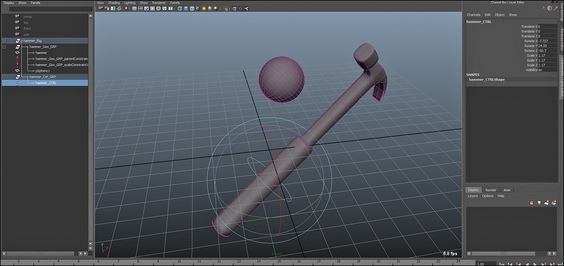
FIGURE 10.9 The sphere “rides” around in the geometry group nicely. We will take advantage of geometry groups frequently with character rigging.
Reset Transformations on your hammer_CTRL once again and select and delete the sphere; we no longer need the sphere because it won’t be a part of our actually hierarchy.
Adding Functionality
We now need to decide what the functionality of this rig should be. Should the hammer be able to squash and stretch, should it be able to bend and twist? All of these questions should be answered by what you need the hammer to do in the animation scenes you have planned. The determining factors will be:
![]() Is the animation cartoony or realistic?
Is the animation cartoony or realistic?
![]() Is the object going to be picked up and passed around a lot?
Is the object going to be picked up and passed around a lot?
![]() Is the object going to attach to several different things over the course of a single shot?
Is the object going to attach to several different things over the course of a single shot?
And many more. For our purposes, let’s assume that our scenes are going to be slightly cartoony, and so we’ll want to add a little bit of bending to the hammer so that as a character swings the hammer, it can bend a little bit in air. This effect will give more impact to a fast swing, and is easy to set up.
Creating the Bend
Maya is packed with powerful deformation tools. Creating a bend control for the hammer is actually quite easy. Follow these steps to do so:
![]() Select the hammer geometry.
Select the hammer geometry.
![]() Switch to the Animation menu set by pressing F2.
Switch to the Animation menu set by pressing F2.
![]() Click on Create Deformers, Non Linear, Bend.
Click on Create Deformers, Non Linear, Bend.
![]() Move the bend so that its center is at the point where the top of the hammer handle meets the shaft.
Move the bend so that its center is at the point where the top of the hammer handle meets the shaft.
![]() In the Channel Box, click on “bend1” under Inputs.
In the Channel Box, click on “bend1” under Inputs.
![]() Change Low Bound to 0.
Change Low Bound to 0.
![]() In the Outliner, select bend1Handle and Ctrl-click on hammer_Geo_GRP.
In the Outliner, select bend1Handle and Ctrl-click on hammer_Geo_GRP.
![]() Press P to parent the bend handle under the geo group. The bend will now follow the movements of the group.
Press P to parent the bend handle under the geo group. The bend will now follow the movements of the group.
We’re almost done. We want to control the amount of bend with the one control we’ve created. These next steps will make it so our hammer_CTRL will control the amount of bend in the hammer:
![]() Select the hammer_CTRL.
Select the hammer_CTRL.
![]() In the Channel Box, click on Edit, Add Attribute.
In the Channel Box, click on Edit, Add Attribute.
![]() Make the long name “Bend,” make the Minimum –8, the Maximum 8, and the default 0. Leave everything else the same and click Add.
Make the long name “Bend,” make the Minimum –8, the Maximum 8, and the default 0. Leave everything else the same and click Add.
![]() Click on Windows, General Editors, Connection Editor.
Click on Windows, General Editors, Connection Editor.
![]() The control’s attributes will load on the left automatically. Click on bend1 in the Channel Box, and in the Connection Editor, click on Load Right.
The control’s attributes will load on the left automatically. Click on bend1 in the Channel Box, and in the Connection Editor, click on Load Right.
![]() In the left pane of the Connection Editor, scroll to the bottom and click on “bend.”
In the left pane of the Connection Editor, scroll to the bottom and click on “bend.”
![]() Scroll down in the right pane of the Connection Editor until you find the “curvature” attribute and then click on it.
Scroll down in the right pane of the Connection Editor until you find the “curvature” attribute and then click on it.
Now the hammer_CTRL’s “bend” attribute actually controls the amount of bend in the hammer. Test it out by selecting hammer_CTRL and MMB dragging the “bend” attribute back and forth in the Channel Box. You should get results like Figure 10.10.

FIGURE 10.10 The bend deformer being controlled by the hammer_CTRL. Everything is working as expected. You now have a bending hammer rig!
![]() Video: Good Prop Rigging Workflow
Video: Good Prop Rigging Workflow
In this bonus video, I demonstrate rigging a prop for animation. We will walk through all of the important steps, and you will get to see a good workflow in practice. In particular, note how meticulously I pay attention to issues such as freezing transforms, making neatly organized groups, and using a naming convention.
Summary
It is highly recommended you put the time in to create controls rigs for your animated objects. A rig will give you many added benefits over simply manipulating the geometry—most notably the ability to reuse modifications to a mesh across multiple scene files. You must first prepare your mesh for rigging, by removing history and centering the object in the scene. Next, create a few nested groups that will contain the different types of objects contained in a rig. This is done for organization, as well as for the functionality of being able to freely add objects to the geometry group. Last, add your controls in the form of NURBS curves and set up the relationships. Decide on extra functionality you need and add this functionality in the form of extra attributes to your rig.
Q&A
Q. Why is my pivot outside my object when I center it?
A. When you center your pivot, Maya averages the position of all of the vertices and places the pivot where that average is. For some meshes, that means it will be outside the shell of the polygons. A torus, or donut shape, for example, has a pivot centered where there is no geometry encasing it.
Q. I have seen NURBS curves in very different shapes on rigs in the past. How do I make those?
A. Any NURBS curve is acceptable for a controller. You can download many tools online that provide free controllers for use in rigging, or you can create them yourself. Using the EP Curve tool, you can try drawing some shapes in panel that indicate what a controller is used for. For instance, it’s common that eye controllers are shaped like eyeballs.
Q. Why do we need so many groups?
A. Three groups is nothing! Groups offer a lot of functionality. First, they let you organize your objects. They also act as “containers” for your objects, allowing you to manipulate more than one object at a time. Complex rigs might have dozens of groups for the sole purpose of giving fine control over objects.
Q. I can scale both the hammer_Rig and the hammer_CTRL. Which one should I use to scale the hammer?
A. You have stumbled across a common issue in rigging. Sometimes more than one control offers the same functionality. If it is a good rig, you need only choose the control that makes sense to you and stick with it. Most often, though, you want to do all of your animation with the controls that have been specifically created to perform a function; look for NURBS curves provided for you and use those over using groups in the Outliner.
Workshop
The workshop contains quiz questions and exercises to help you solidify your understanding of the material covered. Try to answer all questions before looking at the “Answers” section that follows.
Quiz
1. What is the hotkey for creating a group?
2. Clearing transforms and setting an object’s current position to 0,0,0 and scale to 1 is called doing what?
3. All controls on a proper rig are made from what type of geometry?
4. What group would you add an object to in order for it to be moved by the hammer_CTRL?
5. Adding an attribute to a controller is best achieved through which panel?
Exercise
Try creating a rig for another prop you have modeled. Don’t forget to spend a little time preparing the model for rigging by removing history, centering the object, and freezing transforms. Follow the same protocol we used to rig this hammer, and think ahead in terms of what kind of functionality your object will need. Should it squash, stretch, twist? Start simple and don’t get ahead of yourself; we’ll move onto more complex rigs in the next Hour.
Answers
1. Ctrl+G creates a group, and will place selected objects into that group. If no objects are selected, Maya creates an empty group (which is just a transform node).
2. This is called “freeze transformations,” and is accessible by clicking Modify, Freeze Transformations.
3. A good rig has only NURBS curves as controllers. They are easy to see, do not render, and are simple to manipulate.
4. “hammer_Geo_GRP” is constrained to the control, so all objects within this group move with it.
5. The Channel Box is the simplest panel to use. Click on Edit, Add Attribute to add any custom attribute to any selected object.