
Hour 11. Character Rigging: Articulating Characters
What You’ll Learn in This Hour:
![]() How to create skeleton systems for characters
How to create skeleton systems for characters
![]() How to use curves as controls
How to use curves as controls
![]() How to connect the curves to your skeleton
How to connect the curves to your skeleton
![]() What other types of controls there are on a character rig
What other types of controls there are on a character rig
To create realistic and engaging character performances, 3D artists must first create all of the articulation in the model. The limbs must be able to bend, the body must be able to deform, the mouth must open and close, and so on. We’ve created a simple rig for your hammer prop; now it’s time to see how skeleton systems work. We will use a combination of joints and deformers to make a rig for our character.
Tip: Track Your Progress
Rigging can be finicky in Maya. It is also cumbersome to remember the steps you have taken in your rigging process, no matter what program you are using. Especially if you are taking multiple work sessions to complete a rig, you should keep a log of what you have done. Then, when you sit down to work further on your rig, you will not be lost as you stare at a half-completed rig. Also, this log will serve as a record of what is working and what is not, allowing you to troubleshoot the rig as it is created.
In this hour, you will create a character rig for our character, Sam. In doing so, you will be exposed to skeleton systems in Maya and how to correctly place and order joints. When you are finished with the joints, you will create controllers and deformers that give the character extra articulation, which in turn allows an animator to create richer, more entertaining performances.
Joints
Skeleton systems in Maya are made up of connected objects called joints. It can be a little confusing at first to say “joint” when you mean a bone, but the confusion quickly subsides when you realize that the only information that is really essential to a joint is the rotation of its pivot. Therefore, we are really only concerned with the actual joint itself, because it tells us the orientation of the bone it is connected to. Don’t worry if it still seems hard to grasp because we’ll create some joints and see exactly what it means to connect them. Do as follows:
![]() Create a new scene in Maya.
Create a new scene in Maya.
![]() Switch to the Animation menu set (F2).
Switch to the Animation menu set (F2).
![]() Click on Skeleton, Joint Tool.
Click on Skeleton, Joint Tool.
![]() In the Persp panel, click anywhere on the grid to place your first joint; then click two more times to create a simple skeleton, like in Figure 11.1
In the Persp panel, click anywhere on the grid to place your first joint; then click two more times to create a simple skeleton, like in Figure 11.1
![]() Exit out of the Joint tool by pressing E to switch to the rotate tool; we’ll rotate the joints later on, but for now let’s discuss what was created.
Exit out of the Joint tool by pressing E to switch to the rotate tool; we’ll rotate the joints later on, but for now let’s discuss what was created.

FIGURE 11.1 A simple skeleton containing three joints. It sort of resembles an elbow, doesn’t it? These joints contain rotational information that will be used to deform our character later.
Our simple skeleton contains three joints. If you look in the Outliner (Window, Outliner), you will see that the joints are automatically created in a hierarchy according to the order they were created. That’s because a skeleton is, by definition, a hierarchy—joints that rotate their children, which rotate their children, and so on. Think of your arm: Your shoulder rotates your whole arm, the elbow rotates just the forearm, the wrist rotates just the hand. Just like in real life, a joint in Maya rotates all of the joints below it. This relationship is called Forward Kinematics.
Forward Kinematics Versus Inverse Kinematics
Any simple joint chain is considered an “FK Chain.” Forward Kinematics (FK) means that each joint moves and rotates its children. In our case, Joint 1 rotates Joints 2 and 3, Joint 2 only rotates itself and Joint 3, and so on. The other type of motion you can apply to a skeleton system is called inverse kinematics (IK). This type of motion allows a child joint to dictate the orientation of the parent joints. However, this type of motion also requires a solver (a small calculation running in the background of Maya) to work correctly. To see the difference between FK and IK, follow these simple steps. (Make sure there is nobody standing next to you, or they might get whacked!)
![]() Hold your right arm out to your side.
Hold your right arm out to your side.
![]() Place your left finger in the bend of your right elbow, and bend just your elbow. Imagine that in Maya you have selected the elbow joint and are rotating it.
Place your left finger in the bend of your right elbow, and bend just your elbow. Imagine that in Maya you have selected the elbow joint and are rotating it.
![]() Notice that when you bend just your elbow, your hand moves with your forearm. This is Forward Kinematics. All of the child joints of the elbow are “along for the ride.”
Notice that when you bend just your elbow, your hand moves with your forearm. This is Forward Kinematics. All of the child joints of the elbow are “along for the ride.”
![]() Now grab your right wrist with your left hand.
Now grab your right wrist with your left hand.
![]() Relax your right hand so that the left hand is holding 100% of the weight of the arm.
Relax your right hand so that the left hand is holding 100% of the weight of the arm.
![]() Move your right wrist around with your left hand.
Move your right wrist around with your left hand.
![]() Notice how your shoulder and elbow both bend so that you are able to move your wrist where you want it.
Notice how your shoulder and elbow both bend so that you are able to move your wrist where you want it.
![]() Imagine in Maya you are grabbing the wrist controller and are placing it where you want it to be, and the elbow and shoulder joints are automatically “solving” to give you the result you want. This is Inverse Kinematics.
Imagine in Maya you are grabbing the wrist controller and are placing it where you want it to be, and the elbow and shoulder joints are automatically “solving” to give you the result you want. This is Inverse Kinematics.
We will build a skeleton that can utilize both FK and IK in our rig, as certain character movements require access to either FK or IK motion.
Starting a Rig
A little bit of cleanup is necessary before you start a rig. Open sam_Rig_Start.ma in this Hour’s source files. As you can see in Figure 11.2, Sam has been positioned so he is “standing” on the ground, and his pivot repositioned to the world origin. This makes things easy to see if you are creating the rig in the correct position.
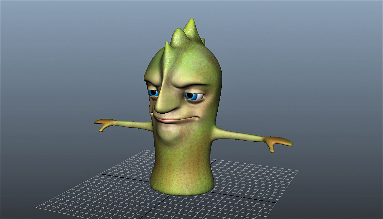
I have also deleted history on the model and created a simple texture for our character. Texturing can be done at any point after UVs are created.
Caution: Changing the Model
It is quite cumbersome to change topology of a character after it is skinned (attached to a rig). However, at this point, the position of the model is all that we are concerned with. It is typical for riggers to start a rough rig at the same time modeling is being completed, all while the texture artists are developing the look.
![]() Activate the Joint tool by going to Skeleton, Joint Tool.
Activate the Joint tool by going to Skeleton, Joint Tool.
![]() In the front panel, press and hold the X key to snap to grid lines and then click on the world origin. A joint will appear.
In the front panel, press and hold the X key to snap to grid lines and then click on the world origin. A joint will appear.
![]() Still holding X, place two more joints above the first, spaced every other grid line, as in Figure 11.3.
Still holding X, place two more joints above the first, spaced every other grid line, as in Figure 11.3.
![]() When you are done, press Enter.
When you are done, press Enter.

FIGURE 11.3 The three joints of the spine. We snapped to the grid lines because we want our skeleton directly in the middle of the rig.
Let’s keep going:
![]() Select the Joint tool again or press Y to activate the last tool.
Select the Joint tool again or press Y to activate the last tool.
![]() In the front panel, click on the top spine joint to connect newly placed joints to this chain. Place a joint just to the right of the top spine joint. This joint will be connected to spine4.
In the front panel, click on the top spine joint to connect newly placed joints to this chain. Place a joint just to the right of the top spine joint. This joint will be connected to spine4.
![]() Click again at the root of the shoulder to place a joint there.
Click again at the root of the shoulder to place a joint there.
![]() Place a joint at the center of the elbow.
Place a joint at the center of the elbow.
![]() Place joints on the wrist, the first knuckle, and the second knuckle. When you are done, press Enter, and your joints should look like Figure 11.4.
Place joints on the wrist, the first knuckle, and the second knuckle. When you are done, press Enter, and your joints should look like Figure 11.4.
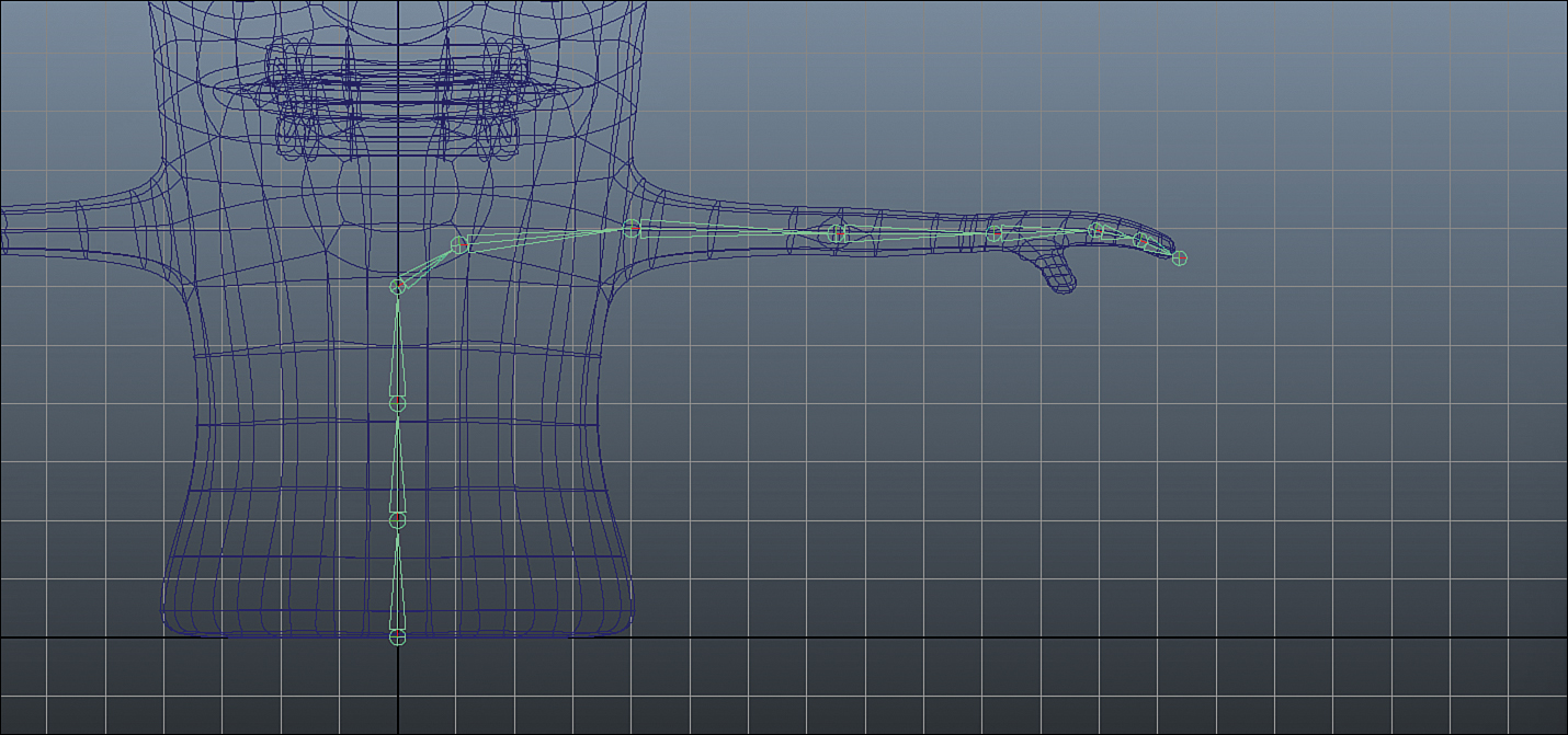
FIGURE 11.4 The arm joints are placed in the front panel. We only need two knuckles in a “mitten” type of hand because it doesn’t have the resolution or detail of a realistic hand.
![]() Starting with the first bone, select the bones you’ve created, one at a time, and in the Channel Box, rename them to Spine1, Spine2, Spine3, l_Spine4, l_Shoulder, l_UpperArm, l_ForeArm, l_Wrist, l_Knuckle1, and l_Knuckle2, respectively.
Starting with the first bone, select the bones you’ve created, one at a time, and in the Channel Box, rename them to Spine1, Spine2, Spine3, l_Spine4, l_Shoulder, l_UpperArm, l_ForeArm, l_Wrist, l_Knuckle1, and l_Knuckle2, respectively.
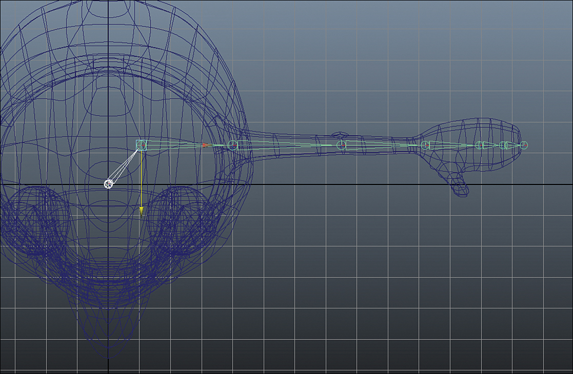
![]() In the top panel, move the arm joints into correct position, as shown in Figure 11.5.
In the top panel, move the arm joints into correct position, as shown in Figure 11.5.
![]() Choose the Joint tool again or press Y. In the top panel, click on the l_Wrist bone to connect newly place joints to this chain.
Choose the Joint tool again or press Y. In the top panel, click on the l_Wrist bone to connect newly place joints to this chain.
![]() Create three joints that represent the thumb, as in Figure 11.6.
Create three joints that represent the thumb, as in Figure 11.6.

FIGURE 11.6 The thumb joints are added. Do not rotate the joints when placing them; instead, use the Move tool. The reason is you want your joints to have zero rotations when you attach the geometry (skinning).
![]() Remember to use the Move tool and not the Rotate tool when positioning the joints.
Remember to use the Move tool and not the Rotate tool when positioning the joints.
![]() Press Enter when you are done and then rename the joints l_Thumb1 and l_Thumb2.
Press Enter when you are done and then rename the joints l_Thumb1 and l_Thumb2.
Tip: Joint Display
Joints have their own scale that is separate from their display size. Maya does this so that you can make joints of any length and not be confused as to the scale of the joint when looking at a skeleton. To make our joints an appropriate size for the model we are using, go to Display, Animation, Joint Size.... In the dialog box that opens, change the size to .5 and press Enter.
Mirroring Joints
We do not want to attempt to re-create the arm joint chain on the other side of our character’s skeleton. Fortunately, Maya has simple commands that allow you to mirror a joint across the world center axis. We will do this to get his right arm joints in place, as follows:
![]() Select the l_Shoulder joint. In the Animation menu set, click on Skeleton, Mirror Joint and the options box
Select the l_Shoulder joint. In the Animation menu set, click on Skeleton, Mirror Joint and the options box ![]() .
.
![]() In the options box, choose the YZ.
In the options box, choose the YZ.
![]() Mirroring has the option to rename joints based on a search string. This is handy so you don’t have to spend a lot of time renaming joints. In the top field, enter l_ and in the bottom field, enter r_.
Mirroring has the option to rename joints based on a search string. This is handy so you don’t have to spend a lot of time renaming joints. In the top field, enter l_ and in the bottom field, enter r_.
![]() Click on Mirror.
Click on Mirror.
![]() You will see your left arm joints are now mirrored into the right arm, as in Figure 11.7.
You will see your left arm joints are now mirrored into the right arm, as in Figure 11.7.

FIGURE 11.7 The arm joints have been mirrored across the center axis. You will also note that the joints have been renamed with the corresponding right-side prefix of “r_”.
Finishing the Joint Chain
We will now place the last few joints to complete this skeleton. Follow these steps:
![]() Load the Joint tool again and in the front panel, while holding X, click on the spine4 joint.
Load the Joint tool again and in the front panel, while holding X, click on the spine4 joint.
![]() Click and place a joint on the center axis one gridline upward in Y.
Click and place a joint on the center axis one gridline upward in Y.
![]() Place another joint one more gridline upward in Y.
Place another joint one more gridline upward in Y.
![]() Place a final joint on the gridline that intersects the top of his head and then press Enter.
Place a final joint on the gridline that intersects the top of his head and then press Enter.
![]() In the Persp panel, move the joints back in Z until they are relatively centered in the character’s head, as shown in Figure 11.8.
In the Persp panel, move the joints back in Z until they are relatively centered in the character’s head, as shown in Figure 11.8.
![]() Rename the two new joints “neck” and “skull.”
Rename the two new joints “neck” and “skull.”
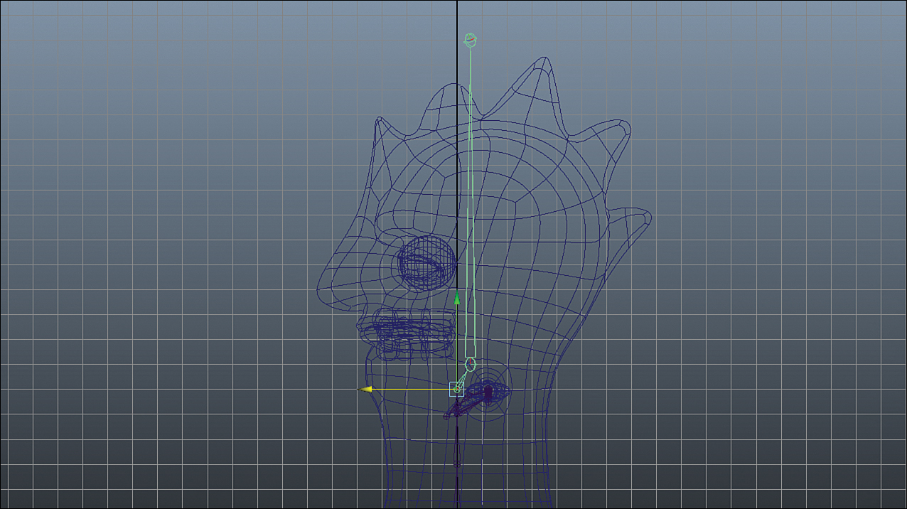
FIGURE 11.8 The rest of the spine (neck and head joints are considered part of the spine) added and moved into the center of the character’s head.
Caution: Extra Joints
Maya draws a visual helper (“bones”) between two joints, so the result of creating a single visual “bone” is actually two joints—one that is the joint you are actually rotating and another to determine the length of the “bone.” Even though for visual reference it is nice to have a “bone” that goes through the geometry, in reality, the very last joint you create will always be useless. Take a look at the joints at the end of the fingers, the thumb, and the head. They all will be excluded from our deformations. Rename all of them to nullJNT1, nullJNT2, and so on.
Jaw Joint
The ideal placement for the jaw is such that the point of rotation will mean that the chin and lower lip geometry won’t shear or intersect into the body too quickly. On a human character, the rotation point would be in front of the ear. On our character, the rotation point should be lower down so that the jaw doesn’t rotate into the body very much. Don’t forget to rename the end joints on the jaw and the head to “null.”
Add the jaw joints, as shown in Figure 11.9.

Joint Orientation
It is good to be in control of the orientation of your joints (in other words, the axes that each joint will use to rotate locally). Selecting the spine1 joint and switching to rotate (press E) shows that locally, the joint wishes to rotate in its Y axis when in actuality it is rotating in the world X axis. This may differ slightly from what you have created, because Maya chooses orientation at creation based on factors such as if the child joint is lined up perfectly along an axis with its parent. It is generally accepted that Y should always point “down” the bone. In Maya, we call this the “primary axis.” We will reorient the joints we’ve created to make sure they have the correct axes. Do as follows:
![]() Shift-select all of the joints in the spine, starting with spine1 and going all the way up to the null joint on top of the head.
Shift-select all of the joints in the spine, starting with spine1 and going all the way up to the null joint on top of the head.
![]() Go to Skeleton, Orient Joint and click the options box
Go to Skeleton, Orient Joint and click the options box ![]() .
.
![]() In the box that opens, choose Orient Joint to World and then click Apply.
In the box that opens, choose Orient Joint to World and then click Apply.
![]() The joints in the spine should be oriented to the world axis now.
The joints in the spine should be oriented to the world axis now.
Because many factors affect the orientation of your joints, the rest of the joints you’ve created may not look like the ones created for this book. Therefore, it will take some experimentation with the Orient tool to make sure your joints are oriented properly. To fast forward to a finished, oriented joint chain, open sam_Rig_Orient.ma. You will see the joints have been all oriented so that the Y axis points “down” the joint and that the most common axis of rotation is the X axis. We can add some controls to this chain.
Adding IK to the Arms
We will add an IK handle to the arms to allow you to move them using an IK solver. Therefore, instead of having to rotate the shoulder, elbow, and wrist in that order to attain a certain arm pose, you can simply position the wrist, and the elbow and shoulder will rotate to compensate.
We first need to make sure the arms are going to give the IK solver the correct start orientation. The IK solver will make the elbow bend in the direction that is parallel to the alignment of the joints. Therefore, because we want it to bend in Y, the joints need to be aligned in Y. Do these steps:
![]() Select the shoulder, elbow, and wrist joints in both arms.
Select the shoulder, elbow, and wrist joints in both arms.
![]() In the front panel, hold down X and translate them in Y to the nearest gridline to snap them all to the same Y height.
In the front panel, hold down X and translate them in Y to the nearest gridline to snap them all to the same Y height.
![]() Let go of X and move just the shoulder joints back into position in the middle of the arms.
Let go of X and move just the shoulder joints back into position in the middle of the arms.
![]() Now in the top panel, select both of the elbow joints and move them slightly backward in Z. A tiny little bit will do.
Now in the top panel, select both of the elbow joints and move them slightly backward in Z. A tiny little bit will do.
Follow these few steps to add the IK handle:
![]() In the Animation menu set, click on Skeleton, IK Handle Tool, and the options box
In the Animation menu set, click on Skeleton, IK Handle Tool, and the options box ![]() .
.
![]() In the Tool Settings, under Current Solver, choose ikRPsolver. This is a solver that allows you to create a “pole vector,” or an object that the elbow points at.
In the Tool Settings, under Current Solver, choose ikRPsolver. This is a solver that allows you to create a “pole vector,” or an object that the elbow points at.
![]() Click on the joint l_UpperArm and then click on the joint l_Wrist.
Click on the joint l_UpperArm and then click on the joint l_Wrist.
![]() Maya will create an IK handle on the wrist and exit the tool.
Maya will create an IK handle on the wrist and exit the tool.
![]() Press Y to activate the last tool again, and repeat the process on the right side of the character rig.
Press Y to activate the last tool again, and repeat the process on the right side of the character rig.
![]() With both IK handles created, your rig should look like the one in Figure 11.10.
With both IK handles created, your rig should look like the one in Figure 11.10.

![]() Select the IK handles and move them to test the motion you are getting. Press Z (or undo) to reset their positions back when you are done moving them.
Select the IK handles and move them to test the motion you are getting. Press Z (or undo) to reset their positions back when you are done moving them.
![]() Now we will create the pole vector objects. Click on Create, Locator.
Now we will create the pole vector objects. Click on Create, Locator.
![]() Move the locator while holding down the V key so it will snap to the center of the left elbow joint. Once it is in position, press Ctrl+D to duplicate this locator.
Move the locator while holding down the V key so it will snap to the center of the left elbow joint. Once it is in position, press Ctrl+D to duplicate this locator.
![]() Repeat on the right side. Select both locators and move –5 units in Z, like in Figure 11.11.
Repeat on the right side. Select both locators and move –5 units in Z, like in Figure 11.11.
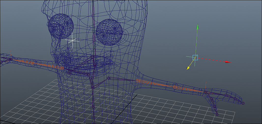
FIGURE 11.11 These locators will be our elbow pole vectors. Here, they are positioned directly behind the elbows so that when they are constrained, the joints will not reorient in any way.
![]() Click Modify, Freeze Transformations.
Click Modify, Freeze Transformations.
![]() Name them l_Elbow_PV and r_Elbow_PV, respectively.
Name them l_Elbow_PV and r_Elbow_PV, respectively.
![]() Select l_Elbow_PV and Shift-select the left wrist’s IK handle. Click on Constrain, Pole Vector. The elbow will now point toward this locator so you may use it to adjust the angle of the arm pose.
Select l_Elbow_PV and Shift-select the left wrist’s IK handle. Click on Constrain, Pole Vector. The elbow will now point toward this locator so you may use it to adjust the angle of the arm pose.
![]() Repeat the constraint on the other side of the mesh.
Repeat the constraint on the other side of the mesh.
![]() Test the results by moving the IK handles, and subsequently moving the pole vector locators.
Test the results by moving the IK handles, and subsequently moving the pole vector locators.
Adding Controls
We will add NURBS curves to our character to serve as controllers on this rig. Commonly the controls will move the joints using constraints. Sometimes controls will be added to edit attributes on nodes connected to the rig. They may even control deformers added on top of the skeleton system.
Open sam_Rig_Controls.ma. This scene has some NURBS controls created for you, as you can see in Figure 11.12.
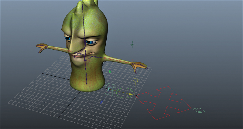
FIGURE 11.12 I’ve gone ahead and loaded some controls into the scene so you do not have to spend time creating these shapes out of NURBS curves.
We now will position the main controller for our character, normally referred to as the “Master”:
![]() Move the large four-pointed arrow object to the world origin by moving it while holding down X.
Move the large four-pointed arrow object to the world origin by moving it while holding down X.
![]() Rename it master_Control.
Rename it master_Control.
![]() Click on Modify, Freeze Transformations.
Click on Modify, Freeze Transformations.
Note: Freezing Everything
When you are creating controls for a rig, you want to freeze transformations on all controls when you have sized and positioned them correctly. This is because you want to be sure if an animator selects all of the controls and resets the transformations to zero, that the rig will be in its “start” position.
![]() Select the circle NURBS object that is on the ground.
Select the circle NURBS object that is on the ground.
![]() Press Ctrl+D to duplicate it.
Press Ctrl+D to duplicate it.
![]() Move the new circle to the spine2 joint by holding down V as you move it. It will snap to vertices as well as joints, so take care in making sure you are snapping it to the right one.
Move the new circle to the spine2 joint by holding down V as you move it. It will snap to vertices as well as joints, so take care in making sure you are snapping it to the right one.
![]() Scale it up so that the curve is a good size outside the mesh of the character.
Scale it up so that the curve is a good size outside the mesh of the character.
![]() Duplicate this curve again by pressing Ctrl+D and position the new curve on the spine3 joint. Size it accordingly.
Duplicate this curve again by pressing Ctrl+D and position the new curve on the spine3 joint. Size it accordingly.
![]() Repeat duplicating, positioning, and scaling until you have controls for all of the joints of the spine (including the head and neck).
Repeat duplicating, positioning, and scaling until you have controls for all of the joints of the spine (including the head and neck).
![]() Once you have positioned (don’t forget to snap by holding down V) and scaled the controls, select them all and click on Modify, Freeze Transformations.
Once you have positioned (don’t forget to snap by holding down V) and scaled the controls, select them all and click on Modify, Freeze Transformations.
![]() Rename these curves to their respective joints. For instance, the curve position at the spine2 joint would be called spine2_CTRL. The abbreviated, uppercase suffix is a good way to distinguish your controls from other NURBS curves you may have in the scene (for modeling purposes or other reasons).
Rename these curves to their respective joints. For instance, the curve position at the spine2 joint would be called spine2_CTRL. The abbreviated, uppercase suffix is a good way to distinguish your controls from other NURBS curves you may have in the scene (for modeling purposes or other reasons).
![]() When you are done, your scene should look like Figure 11.13.
When you are done, your scene should look like Figure 11.13.

![]() Now move the cube control that is on the ground to the lWrist joint by holding V while moving. (You generally want to use different control shapes for different functionalities. In this case, the circle represents FK rotations, and the cube represents IK movement.)
Now move the cube control that is on the ground to the lWrist joint by holding V while moving. (You generally want to use different control shapes for different functionalities. In this case, the circle represents FK rotations, and the cube represents IK movement.)
![]() Scale it to be an appropriate size.
Scale it to be an appropriate size.
![]() Freeze Transformations on the cube.
Freeze Transformations on the cube.
![]() Duplicate it by pressing Ctrl+D.
Duplicate it by pressing Ctrl+D.
![]() Move it to the rWrist joint by holding down V while moving.
Move it to the rWrist joint by holding down V while moving.
![]() Freeze Transformations on this new cube.
Freeze Transformations on this new cube.
![]() Rename the two cubes lWrist_CTRL and rWrist_CTRL, respectively.
Rename the two cubes lWrist_CTRL and rWrist_CTRL, respectively.
![]() Select lWrist_CTRL, duplicate it, and move it to the position of lElbow_PoleVector.
Select lWrist_CTRL, duplicate it, and move it to the position of lElbow_PoleVector.
![]() Scale it down, freeze transforms, and then repeat the duplicate+freeze process for the right pole vector. (We want all controls to be NURBS curves, remember? We’ll have to replace the locator with this cube.) It should look like Figure 11.14.
Scale it down, freeze transforms, and then repeat the duplicate+freeze process for the right pole vector. (We want all controls to be NURBS curves, remember? We’ll have to replace the locator with this cube.) It should look like Figure 11.14.

Remember, Forward Kinematics means that a parent joint will move its child joints, which in turn will move its child joints, and so on. We added an IK handle to our character’s arms. Therefore, the arms will be controlled by translating the wrist controls and then positioning the elbow using the elbow pole vector.
Note: FK/IK Switches
Commonly, rigs are made so that you can switch between FK and IK control on the limbs. Although this is a great trick to know, it would take too many pages to include in this hour. The basic concept is you use the ikBlend attribute on an ikhandle to change between FK and IK on an IK chain. You need to constrain controls for FK rotations to each joint in addition to constraining an IK control for the IK movement. You can give it a try if you’d like, and look at the finished rig included with this Hour’s extra files to see this switch in action.
I have taken the liberty of adding the controls on the fingers. I did this because we needed to parent the finger controls under a group that has been rotated to be aligned with the joints of the fingers. In the next section, you will start from this file.
Connecting Controls
The final step of adding controls is connecting them to the joints. In most cases, we will use constraints to connect the controls. Open sam_Rig_Controls_Done.ma and see the controls in the correct positions. There is also a world_Mover_CTRL that is added to give us the ability to position and scale the entire rig before creating animation. Follow these steps to connect the controls:
![]() We first need our controls to be in the correct hierarchy before we connect the joints. Select head_CTRL, Shift-select neck_CTRL, and then press P. The head is now a child of the neck.
We first need our controls to be in the correct hierarchy before we connect the joints. Select head_CTRL, Shift-select neck_CTRL, and then press P. The head is now a child of the neck.
![]() Select neck_CTRL, Shift-select spine4_CTRL, and then press P.
Select neck_CTRL, Shift-select spine4_CTRL, and then press P.
![]() Repeat these steps until you have created the hierarchy of the spine all the way down to master_CTRL, which should be the uppermost parent node.
Repeat these steps until you have created the hierarchy of the spine all the way down to master_CTRL, which should be the uppermost parent node.
![]() Don’t forget to add jaw_CTRL by parenting it to head_CTRL.
Don’t forget to add jaw_CTRL by parenting it to head_CTRL.
Normally, IK hands stay completely independent of the spine hierarchy so they can be placed on an object and stay still as the rest of the body moves. We’ll leave them out of the spine hierarchy, but we’ll make them part of world_Mover_CTRL’s hierarchy so they scale and move with the entire rig if you want to position Sam in your scene. Select both instances of wrist_CTRL and both instances of elbow_PoleVector and then Shift-select world_Mover_CTRL and press P. Parent eye_Target_CTRL to world_Mover_CTRL as well. Now we’ll connect the joints to these controls:
![]() Select master_CTRL and Shift-select the spine1 joint.
Select master_CTRL and Shift-select the spine1 joint.
![]() In the Animation menu set (F2), click on Constrain, Parent, and the options box
In the Animation menu set (F2), click on Constrain, Parent, and the options box ![]() .
.
![]() In the options box, click on Edit, Reset Settings and then click Add.
In the options box, click on Edit, Reset Settings and then click Add.
![]() With the control and the joint still selected, click on Constrain, Scale and the options box
With the control and the joint still selected, click on Constrain, Scale and the options box ![]() .
.
![]() In the options box, click on Edit, Reset Settings. Then click on Maintain Offset. Click Add.
In the options box, click on Edit, Reset Settings. Then click on Maintain Offset. Click Add.
![]() You do not need to change these settings anymore; once will do.
You do not need to change these settings anymore; once will do.
![]() One by one, select a control in the spine and then Shift-select its corresponding joint. Create a parent constraint and then a scale constraint.
One by one, select a control in the spine and then Shift-select its corresponding joint. Create a parent constraint and then a scale constraint.
![]() Move all the way up the spine to the jaw creating these constraints.
Move all the way up the spine to the jaw creating these constraints.
![]() When you get to spine4_CTRL, you should create the parent and scale constraint for not only the spine4 joint, but also both the left and right shoulder.
When you get to spine4_CTRL, you should create the parent and scale constraint for not only the spine4 joint, but also both the left and right shoulder.
![]() You should also parent and scale constrain the null joints on the top of the spine and the end of the jaw to their respective controls. This solves common scaling issues.
You should also parent and scale constrain the null joints on the top of the spine and the end of the jaw to their respective controls. This solves common scaling issues.
The arm joints are always going to get their position information from the IK Solver, but they need scale information from somewhere if they are going to scale with the rest of the rig correctly. Use the Connection Editor to connect the scale of the lShoulder joint to the scale of the lUpperArm and lLowerArm joints, and the same for the right side. You have to create each connection individually; you cannot batch-create these connections. Remember to load the shoulder joints on the left side of the Connection Editor because they are the nodes “driving” the attributes on the right.
Connecting the IK Hand Controls
Now we connect the controls for the arms to the IK handles and pole vectors. Follow these steps:
![]() Select lWrist_CTRL and Shift-select the left IKHandle.
Select lWrist_CTRL and Shift-select the left IKHandle.
![]() Click Constrain, Parent. (IKHandles do not need scale information.)
Click Constrain, Parent. (IKHandles do not need scale information.)
![]() Click lElbow_PoleVector_CTRL and Shift-select the locator called lElbow_PV.
Click lElbow_PoleVector_CTRL and Shift-select the locator called lElbow_PV.
![]() Click Constrain, Parent. (Pole vectors do not need scale information.)
Click Constrain, Parent. (Pole vectors do not need scale information.)
![]() Repeat these constraints on the right side.
Repeat these constraints on the right side.
![]() I created groups to hold the finger controls, so these need to be parented to the wrist controls. In the Outliner, select the group lFinger_Ctrl_GRP, Shift-select lWrist_CTRL, and press P.
I created groups to hold the finger controls, so these need to be parented to the wrist controls. In the Outliner, select the group lFinger_Ctrl_GRP, Shift-select lWrist_CTRL, and press P.
![]() Repeat the same on the right side.
Repeat the same on the right side.
![]() Parent and scale constrain the controls of the hand to the joints of the hand, starting with the wrist and going to the ends of the fingers and thumb. Remember to parent and scale constrain the null joints as well.
Parent and scale constrain the controls of the hand to the joints of the hand, starting with the wrist and going to the ends of the fingers and thumb. Remember to parent and scale constrain the null joints as well.
Other Controls
So far, our controls are primarily translation and rotation controls. These controls are essential to make the character move, but what about making the character change facial expressions, employing extra articulation, or simply looking at the control we built for him already? There are other categories of controls than the simple transformation controls. Primarily, these controls edit other attributes such as BlendShapes, material attributes, dynamic channels, and so on. We will first create a control that will house all of our BlendShape channels so they are easily accessed when we’re working with the character in panel. We will then create an Aim Constraint for Sam’s eyeballs to eye_Target_CTRL so an animator will be able to control the direction of his eyes.
As mentioned before, most production rigs allow the animator to switch between FK and IK movement on certain parts of the character—normally the arms, legs, and spine. You would normally place the switch close to the limb that is being switched, but it is also common for there to be a single master switch control that holds all of the channels for switches in the rig. Either is fine, but make sure the control shape is unique to the switch so you do not visually clutter your rig with controls that are indistinguishable from each other.
BlendShape Control
Sam will have facial performance animated via BlendShapes. This deformer type in Maya allows the animator to blend between different poses of the face (covered fully in Hour 15, “Making Diverse Shapes with BlendShapes”). However, like most deformers, the attributes for a BlendShape node are difficult to access while performing other animation tasks such as transforming controls and editing keyframes. It is therefore very common to create a control that has attributes connected to the BlendShape attributes. Follow along to create this control:
![]() Import the face control by clicking File, Import. Navigate to this Hour’s files, choose face_CTRL.ma, and then import.
Import the face control by clicking File, Import. Navigate to this Hour’s files, choose face_CTRL.ma, and then import.
![]() The face_CTRL loads into the scene next to Sam’s head. You will notice the transforms are locked.
The face_CTRL loads into the scene next to Sam’s head. You will notice the transforms are locked.
![]() Select the face_CTRL curve (the one that is the shape of the head). Shift-select Sam’s skull_CTRL and press P.
Select the face_CTRL curve (the one that is the shape of the head). Shift-select Sam’s skull_CTRL and press P.
![]() Now the control is parented under the skill control.
Now the control is parented under the skill control.
![]() We will be using the curves in this control group to manipulate the BlendShape attributes.
We will be using the curves in this control group to manipulate the BlendShape attributes.
Eye Target
The eye_Target_CTRL is present and accounted for, but it does not control his eyes yet. To make this connection, we are going to use a type of constraint we never have before, called an “aim constraint.” This type of constraint does exactly what the name says: It makes one object “aim” at another, by rotating the object to face the other along a certain axis. Follow these instructions to get the aim constraint set up:
![]() Select lEye_CTRL (the eye-shaped curve that is within the box-shaped curve floating in front of Sam’s face).
Select lEye_CTRL (the eye-shaped curve that is within the box-shaped curve floating in front of Sam’s face).
![]() Now Shift-select Sam’s l_Eye_GEO.
Now Shift-select Sam’s l_Eye_GEO.
![]() In the Animation menu set, click Constrain, Aim and the options box
In the Animation menu set, click Constrain, Aim and the options box ![]() .
.
![]() In the settings box that opens, click on Edit, Reset Settings.
In the settings box that opens, click on Edit, Reset Settings.
![]() Now make sure Maintain Offset is checked on.
Now make sure Maintain Offset is checked on.
![]() Click on Apply.
Click on Apply.
![]() Now select rEye_CTRL and Shift-select r_Eye_GEO.
Now select rEye_CTRL and Shift-select r_Eye_GEO.
![]() In the settings window for the aim constraint that is still open, click on Add.
In the settings window for the aim constraint that is still open, click on Add.
![]() The settings box will close and you will be able to check to make sure it worked by selecting eye_Target_CTRL and moving it around and seeing if the eyes follow the movement, as in Figure 11.15.
The settings box will close and you will be able to check to make sure it worked by selecting eye_Target_CTRL and moving it around and seeing if the eyes follow the movement, as in Figure 11.15.

Final Cleanup
There are just a few tasks to complete before this rig is ready for skinning. We should make groups for the different objects, make display layers, and hide objects we are not going to ever touch. To do so, follow these steps:
![]() Select both IK handles and both pole vector locators.
Select both IK handles and both pole vector locators.
![]() Press Ctrl+G to group these objects. Rename the group sam_DNT_GRP. (DNT stands for do not touch.)
Press Ctrl+G to group these objects. Rename the group sam_DNT_GRP. (DNT stands for do not touch.)
![]() Select this new group and then Ctrl-select the group sam_Rig_GRP in the Outliner.
Select this new group and then Ctrl-select the group sam_Rig_GRP in the Outliner.
![]() Press P. The DNT group is parented under the main rig group.
Press P. The DNT group is parented under the main rig group.
![]() Select joint1. Press Ctrl+G to group the joint, and then rename the new group sam_Skeleton_GRP.
Select joint1. Press Ctrl+G to group the joint, and then rename the new group sam_Skeleton_GRP.
![]() Parent this under the main rig group as well.
Parent this under the main rig group as well.
![]() Select world_Mover_CTRL. Create a new group for this as well, rename it sam_Ctrl_GRP, and parent it under the main rig group.
Select world_Mover_CTRL. Create a new group for this as well, rename it sam_Ctrl_GRP, and parent it under the main rig group.
![]() Hide the DNT group. Your Outliner should look like Figure 11.16.
Hide the DNT group. Your Outliner should look like Figure 11.16.

![]() Select the group sam_geo_GRP and in the Channel Box, Layer Editor (at the bottom right of your screen), click on Layers, Create Layer from Selected.
Select the group sam_geo_GRP and in the Channel Box, Layer Editor (at the bottom right of your screen), click on Layers, Create Layer from Selected.
![]() Rename this new layer sam_Geo_LAYER.
Rename this new layer sam_Geo_LAYER.
![]() Select the group sam_Ctrl_GRP and click on Layers, Create Later from Selected.
Select the group sam_Ctrl_GRP and click on Layers, Create Later from Selected.
![]() Rename this new layer sam_Ctrl_LAYER.
Rename this new layer sam_Ctrl_LAYER.
![]() Create another layer from sam_Skeleton_GRP and name it accordingly.
Create another layer from sam_Skeleton_GRP and name it accordingly.
![]() Your Layer Editor should resemble the one in Figure 11.17.
Your Layer Editor should resemble the one in Figure 11.17.
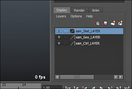
FIGURE 11.17 The Layer Editor properly configured with our display layers. Now we can move on to skinning!
This file has been saved for you as sam_Rig_Final.ma.
Now that we have cleaned up our scene, we are ready to make our rig deform our geometry using the Skin deformer. We are going to have a lot of fun attaching Sam’s geo to this rig, especially when we are able to start animating him around and bringing him to life!
![]() Video: Advanced Rigging Techniques
Video: Advanced Rigging Techniques
In this video, I show off some of the more advanced features of the Sam 2.0 rig, which also ships with this book, and how to create some of these features, such as FK/IK switches, deformation in the spine controls, and more.
Summary
Simple object rigs are a combination of groups, constraints, and controls. When you start creating character rigs, joints are added into the mix. You should be aware that joints are not used solely for organic characters. In fact, car rigs, spaceship rigs, and many other mechanical or non-living objects typically make use of joints in production. We created a skeleton and took advantage of mirroring. We set up the controls in the right place and then created the hierarchy and constraints to make them move correctly. We then added a few extra controls to round out our character rig.
Q&A
Q. I’m creating a character with legs. Is the IK solver still the right way to go?
A. Yes, you will mainly be using IK with legs. However, some of the properties of a foot need to be worked out in advance, such as the ability to lift from the toe. Google “reverse foot rig” to find out more.
Q. I can’t seem to create joints that start from the end of my last joint. Maya just creates a new joint on top of the old one. What’s wrong?
A. Most problems in Maya are resolved by a restart of the program. This is one that pops up sometimes.
Q. Why use constraints for making the joints follow the controls instead of parenting?
A. We will go over constraints in detail in Hour 13, “Animation: Adding Movement to Your Scene.” The short answer is that parenting the joints under the controls would change the hierarchy of the joints, which we do not want to do. Also, constraints can be dynamic, meaning in advanced rigging we can adjust how the controls actually move the joints.
Q. When I tried to orient my joints, I did not come up with the nicely oriented joints that you did. Why?
A. As mentioned, orienting your joints is a trial-and-error process, and you may not get the results you are looking for on the first try. Also, be careful; there is an option to reorient the child joints of the selected joint when you orient. This can mess up correctly oriented joints easily.
Workshop
The workshop contains quiz questions and exercises to help you solidify your understanding of the material covered. Try to answer all questions before looking at the “Answers” section that follows.
Quiz
1. Why are the “bones” in Maya called joints?
2. What do FK and IK stand for?
3. What type of movement did we create in our character spine: FK or IK?
4. What do we call the extra joint at the very end of a joint chain?
5. What is the name of the constraint that makes an object rotate to face another object?
Exercise
Take a look at the Maya file sam_Rig_v2.0.ma. This rig has some cool additions to the rig we created in this Hour. Although rigging to this level is outside the scope of this book, you should be able to open up the Outliner and Hypergraph and see how the objects are connected. After watching Video 11.1, see if you can reconstruct some of the more advanced rigging concepts we went over in the video. In particular, you might want to try making an FK/IK switch on your version of Sam’s rig. Create circle controls on his shoulder, elbow, and wrist, and constrain the joints to these controls in addition to the IK wrist and pole vector controls you’ve already made. Adjusting the IKBlend attribute on the IKHandles will make the bones either snap to the IK solver position or back to the position of the FK controls you’ve made. Giving good switches on rigs is a top priority for most animators.
You may even want to try creating a rig for a very simple character such as a flour sack using the concepts we talked about in this Hour. Just remember to work slowly and log your progress.
Answers
1. Simply because we are constantly using the rotational information from a bone; therefore, the pivot point, or “joint,” is the logical choice.
2. FK stands for “Forward Kinematics” and IK stands for “Inverse Kinematics.” FK is when the parent joint controls the child’s movement, and IK is when you position the child and the parent joints rotate to accommodate, or “solve,” this new position.
3. We used an FK spine for Sam.
4. We rename those to Null so that when skinning, we can disregard their influence on the geometry. You should always remember to include them, however, in the constraining of controls so that scale works properly.
5. An aim constraint makes an object rotate to face, or point at, another object. We used this constraint on the eyes of Sam.