
Hour 12. Skinning: Attaching Geometry to a Rig
What You’ll Learn in This Hour:
![]() How to attach geometry to joints using skin deformers
How to attach geometry to joints using skin deformers
![]() How to decide on rigid binding or smooth binding
How to decide on rigid binding or smooth binding
![]() How to paint weights and refine your smooth bind
How to paint weights and refine your smooth bind
![]() How to add more deformations to your skinned model
How to add more deformations to your skinned model
After your joints and controls have been created, the task of “skinning” your character may begin. Although it sounds like the opposite, skinning is the act of applying the mesh to the rig you have created so it can move along with the controls you have created.
Note: Sam 2.0
In this Hour, we will continue with our character Sam. However, we will start from the 2.0 version of the character rig I created and not the simpler rig you made in the last Hour. If you like, however, you can still use your rig to follow along in this Hour. I recommend that you use the Sam 2.0 rig to see some more dynamic rigging and skinning techniques in action.
In this Hour, you find out how to make your models deform using joints by investigating Rigid Binds and Smooth Binds. We will then attach our character Sam to the control rig we created last Hour. You will see how to clean up the blending between the joints by painting weights, as well as some good methods for smoothing out problem areas in our rig. We will also look at some helpful deformers that provide us with added versatility in the function of our rig.
The Skin Nodes
Maya deforms meshes to move with joints with two different types of “binds”: Rigid Binds and Smooth Binds. Rigid Binds make your geometry behave almost like it is parented to the joint. Smooth Binds make your geometry bend smoothly across joints. Whichever skin node you are using, first it is important to realize the distinction between parenting and skinning. Parenting means that the transform node of an object is a child of the joint, and therefore actually moves with the joint through space. The object’s position changes with the parent’s position. Skinning, on the other hand, is actually a deformer, meaning the object being skinned technically does not move. The vertices of the object deform as the joints move, but if you select the mesh even after doing complex adjustments to its rig, you will see the object’s transforms are still all at 0. This distinction is good for us because it allows us to layer deformers on top of each other without worrying about multiple transformations affecting the object itself. The ordering of the deformers is important, though, and in Hour 15, “Making Diverse Shapes with BlendShapes,” we will make some adjustments to the order of deformers.
Rigid Bind
The first type of bind is called a Rigid Bind. The way Rigid Bind works is that a certain joint can only influence a vertex 100% or 0%—meaning there is no real blending of the influence, or “weight” of a joint on a mesh. Why would you use a deformer that has no weights? Rigid Binds are commonly compatible with most game engines, and sometimes offer a better alternative to parenting for rigid objects. As you will see as we add deformers to a skinned mesh, keeping mesh transformations and deformations separated is important to keep things from getting overly complex; you can quickly create some very undesirable results if you are not careful mixing deforms and transforms.
Open rigid_Skin.ma in this Hour’s files. This is a basic file that has some geometry positioned over joints, much akin to a robot arm. Rigid Binds are commonly used for skinning rigid objects such as robots and cars (yes, even cars have rigs).
As you can see in Figure 12.1, the geometry is placed exactly where it should be. Rigid Binds are much like parent constraints in that the position of the mesh relative to the joint cannot be changed once it is skinned. If you are looking for additional control over the position of the mesh relative to the joint, perhaps a constrained group (as in Hour 9, “Relationships and Making Nodes Work Together”) or a parent relationship is more appropriate.

Using Rigid Bind means that the joints will actually deform the vertices of the mesh that is bound to them. Remember this important distinction: An object that is transformed has a position that changes in world space, found at that object’s pivot point. On the other hand, an object that is skinned will seem to move through space as the joints move, but its pivot will not move at all. Only the vertices will move. Let’s Rigid Bind this arm and test this theory:
![]() Select the joint labeled upper_Arm. Shift-select the mesh labeled upper_Arm_GEO.
Select the joint labeled upper_Arm. Shift-select the mesh labeled upper_Arm_GEO.
![]() Press F2 to switch to the Animation menu set.
Press F2 to switch to the Animation menu set.
![]() Click on Skin, Bind Skin, Rigid Bind and then choose the options box
Click on Skin, Bind Skin, Rigid Bind and then choose the options box ![]() .
.
![]() Change the Bind To option to Selected Joints and click Bind Skin.
Change the Bind To option to Selected Joints and click Bind Skin.
![]() Repeat this process for the forearm joint and forearm geometry.
Repeat this process for the forearm joint and forearm geometry.
Once the meshes have been skinned using Rigid Bind, select and move the IK handle around in the scene. The meshes follow the movement of the joints. But let’s see the difference between parenting and binding geometry. Select the hand geometry. You will see the hand geometry’s pivot point moves along with the wrist joint. This is because the object’s transform node is being moved as a child of the joint. Now select the forearm geometry. Notice how the pivot point is always at the world origin, no matter what pose the arm skeleton takes. As in Figure 12.2, no matter how you manipulate the IK handle or rotate the joints, the forearm and upper arm geometry will have a pivot that remains still.

FIGURE 12.2 Because the geometry is bound, and not parented, the vertices are being “deformed” into position by the joints, not translated. Notice the pivot is still in place because the transform node hasn’t moved.
Imagine the vertices are being glued to the joint, but the transform node that acts as a container does not move at all. Remember, Rigid Bind is useful for game engines and rigid geometry.
Flexors
If you need extra deformation, Flexors allow you to create custom shapes at the intersections of joints, leading to more smooth transitions between joints. Flexors are easy to create. Follow these steps to add one:
![]() Open flexor.ma in this Hour’s files.
Open flexor.ma in this Hour’s files.
![]() We have a tube that is skinned to the joints using Rigid Bind. Select the joints and rotate them a bit to see the harsh, jagged bind.
We have a tube that is skinned to the joints using Rigid Bind. Select the joints and rotate them a bit to see the harsh, jagged bind.
![]() Click undo to get the joints back to their start position.
Click undo to get the joints back to their start position.
![]() Switch to the Animation menu set by pressing F2.
Switch to the Animation menu set by pressing F2.
![]() Select the forearm joint.
Select the forearm joint.
![]() Click on Skin, Edit Rigid Bind, Create Flexor....
Click on Skin, Edit Rigid Bind, Create Flexor....
The three different types of Flexors are Lattice, Sculpt, and Joint Cluster. The Lattice type creates a lattice around the joint that will allow for smoother blending. The Sculpt type creates a manipulator that will affect the geometry by scaling and bulging. The Joint Cluster type creates a cluster at the joint that has a falloff allowing for smooth bends, much like the Lattice.
![]() Make sure the type is set to Lattice and click Create.
Make sure the type is set to Lattice and click Create.
![]() Bend the joints again and see how the Flexor makes it so there is a smooth transition between the joints.
Bend the joints again and see how the Flexor makes it so there is a smooth transition between the joints.
Deform vs. Transform
We’ve brought up the importance of distinguishing between deforming and transforming a few times. The main reason we should be careful is because of the way that Maya handles adding more than one deformation to the same model. The order of the deformations makes a big difference. For instance, in Figure 12.3, you can see the difference between first applying a Twist and then a Bend deformer, and the result if the order is switched.

FIGURE 12.3 On the left is a tube that has a Twist and then a Bend deformer applied. On the right is the same tube with the deformer order switched. Deformer order matters, and mixing transforms and deforms together can have even more unpredictable results.
As you can clearly see, the order of deformations makes a huge difference. This is pertinent to the discussion of deform versus transform because when you transform geometry, you are effectively moving the “container” (transform mode) that holds the shape. Moving this container also moves the vertices in the shape node, and can result in very undesirable results. In Hour 15, we will go over BlendShapes, the most common deformer used in conjunction with skinning. Deformation order will play a big role there as well, and we will show how mixing transforms and deforms can get messy.
Smooth Bind
The other type of bind is called a Smooth Bind. When it comes to characters, you will use the Smooth Bind tool to get your meshes skinned to your rigs. Remember, we are going to be using the Sam 2.0 rig that I’ve created so as to have even better control than the basic rig created in the last Hour.
When you create a Smooth Bind, you are essentially creating a Skincluster deformer. This deformer allows you to bind the vertices of a mesh to a joint or group of joints. The weight of the bind is controlled by painting the weight in panel, with zero being zero influence, and white being full influence. Let’s get started on Sam.
Skinning Sam
Open sam_Skin_Start.ma in this Hour’s files. This file contains the final Sam model and the final Sam Rig v2.0. We will skin this mesh and adjust the skin weights once finished. Actually applying the Smooth Bind is a simple process. Follow these steps to get the initial bind:
![]() Select Sam’s body geometry.
Select Sam’s body geometry.
![]() Switch to the Animation menu set by pressing F2.
Switch to the Animation menu set by pressing F2.
![]() Click on Skin, Bind Skin, Smooth Bind and the options box
Click on Skin, Bind Skin, Smooth Bind and the options box ![]() .
.
![]() For the options, match my settings as shown in Figure 12.4.
For the options, match my settings as shown in Figure 12.4.

Note: Null Joints and Skinning
Because we are going to only use “Selected Joints” for our skinning, we need to select all of the joints that are going to be used for the skin weights. This is why it is important to know about, label, and keep track of the Null joints in a rig. They are included in the skin weights if you simply select the root joint and choose Hierarchy in the Smooth Bind options. Having these null joints interfere with the skinning is problematic.
![]() Select the following joints by holding Shift while you LMB click on them. We select them in reverse hierarchical order because when you select a parent, the child joints are drawn as selected, too. This way, we can see exactly which joints we’ve selected: lKnuckle2, lKnuckle1, lThumb2, lThumb1, lWrist, lForearm, lUpperArm, lShoulder, rKnuckle2, rKnuckle1, rThumb2, rThumb1, rWrist, rForearm, rUpperArm, rShoulder, skull_JNT, jaw_JNT, neck_JNT, spine4, upperSpine_Shaper_JNT, lowerSpine_Shaper_JNT, and Spine1.
Select the following joints by holding Shift while you LMB click on them. We select them in reverse hierarchical order because when you select a parent, the child joints are drawn as selected, too. This way, we can see exactly which joints we’ve selected: lKnuckle2, lKnuckle1, lThumb2, lThumb1, lWrist, lForearm, lUpperArm, lShoulder, rKnuckle2, rKnuckle1, rThumb2, rThumb1, rWrist, rForearm, rUpperArm, rShoulder, skull_JNT, jaw_JNT, neck_JNT, spine4, upperSpine_Shaper_JNT, lowerSpine_Shaper_JNT, and Spine1.
![]() In the Smooth Bind options box, click Smooth Bind.
In the Smooth Bind options box, click Smooth Bind.
![]() A skincluster node is added to the geometry, the transformations are locked, and the controls will now move the character, albeit roughly.
A skincluster node is added to the geometry, the transformations are locked, and the controls will now move the character, albeit roughly.
![]() Select some of the controls and make sure they are moving the character.
Select some of the controls and make sure they are moving the character.
Painting Weights
If the act of skinning a character seemed too easy, that’s because the work has just begun. We now have to make sense of the skin weights and start smoothing them out. We achieve this by doing what is called “painting weights.” This is the process of using a brush to paint values of color on the surface of the model to distinguish which areas are affected by the joints in our skeleton. Carefully painting smooth values in turn gives us smooth deformation in our model. Painting skin weights is as much an art as a science. Let’s take a look at a few techniques.
Painting
Select Sam’s body geometry and click on Skin, Edit Smooth Skin, Paint Skin Weights Tool. The resulting box looks very similar to all of Maya’s painting windows. The simple workflow is to select a joint in the Tool Settings box and then use the paintbrush to paint the influence of that joint on the body mesh. The whiter the mesh is, the higher the influence. Because Maya creates a default weight mapping for you when it creates a smooth bind, the majority of your time when skinning is spent fixing weights. Let’s put this to practice:
![]() In the Paint Skin Weights tool settings, scroll down in the Influences box until you find Jaw_JNT and select it.
In the Paint Skin Weights tool settings, scroll down in the Influences box until you find Jaw_JNT and select it.
![]() Notice how, like in Figure 12.5, the mesh displays the weight of the joint on the skinned mesh.
Notice how, like in Figure 12.5, the mesh displays the weight of the joint on the skinned mesh.

FIGURE 12.5 The selected joint displays its influence on the skinned geometry. The default skinning of the jaw joint has far too much weight on the head.
![]() We need to move the joint to see just how much weight smoothing needs to be done, so select jaw_CTRL and rotate it down in X about 35 degrees.
We need to move the joint to see just how much weight smoothing needs to be done, so select jaw_CTRL and rotate it down in X about 35 degrees.
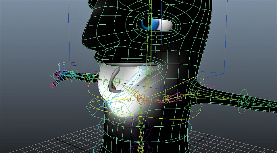
![]() As you can see from Figure 12.6, the jaw JNT is influencing the geometry of the head far too much.
As you can see from Figure 12.6, the jaw JNT is influencing the geometry of the head far too much.
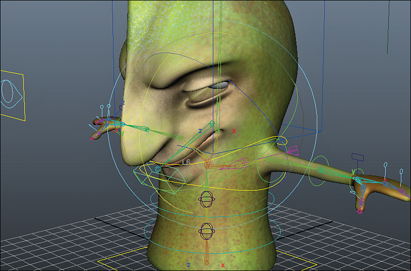
FIGURE 12.6 The jaw JNT is pulling the vertices of the head downward with it. We will have to clean up these weights by using the Paint Skin Weights tool.
![]() Select the body mesh again and press Y to enter the last tool, which should be the Paint Skin Weights tool.
Select the body mesh again and press Y to enter the last tool, which should be the Paint Skin Weights tool.
![]() In the Tool Settings box, select jaw_JNT again under Influences.
In the Tool Settings box, select jaw_JNT again under Influences.
![]() Now move your mouse over the body mesh to see your paintbrush. You can scale the brush by holding down the B key and LMB clicking and dragging while in any brush tool.
Now move your mouse over the body mesh to see your paintbrush. You can scale the brush by holding down the B key and LMB clicking and dragging while in any brush tool.
If you look in the Tool Settings underneath the Influences, the Mode, Operation, and other brush options are available. When we are painting influence, we keep the mode on Paint. The paint operations are as follows.
Replace
This paint mode makes the weight on the painted vertices exactly what the “value” is set to in the tool options by just replacing the weight.
Add
This is an additive brush that will “build” weight as you paint over an area more and more. Similar to an airbrush.
Scale
This is a subtractive brush that will scale the weight on the painted vertices by the value you have set in the tool options (.5 = 50% and so on).
Smooth
This brush simply smooths the weights as you paint over the vertices. You should note that holding down the Shift key makes any of the other paint operations switch to smooth temporarily.
Other Options
The rest of the tool options can be investigated on your own; most are self-explanatory. Make sure before you start painting weights, however, that the Normalize Weights setting is set to Interactive at the top of the tool settings window. This makes it so that the weights are always kept so that the cumulative weight of all the influences of a vertex are 1.0. Follow these steps to start painting weights on Sam:
![]() Switch to the Scale operation in the Tool Settings window, and change the Value to .85.
Switch to the Scale operation in the Tool Settings window, and change the Value to .85.
![]() Use the paintbrush to reduce the weight of jaw_JNT on the face by painting with the LMB across the head, nose, and upper lip.
Use the paintbrush to reduce the weight of jaw_JNT on the face by painting with the LMB across the head, nose, and upper lip.
![]() Your results should start to look like Figure 12.7 as the weight of the jaw starts approaching a more correct value on the vertices of the head.
Your results should start to look like Figure 12.7 as the weight of the jaw starts approaching a more correct value on the vertices of the head.
![]() If you mess up an area, you can undo by pressing Z. If you need to add weight back again, simply switch to the Add operation. Note, however, that adding .85 is extreme; you have to constantly adjust the value of the brush when switching back and forth between Add and Scale.
If you mess up an area, you can undo by pressing Z. If you need to add weight back again, simply switch to the Add operation. Note, however, that adding .85 is extreme; you have to constantly adjust the value of the brush when switching back and forth between Add and Scale.
Continue to paint the weight on the jaw. Rotate the jaw control in different directions to get a sense of how the joint is deforming the mesh, and adjust the weights to smooth the deformations.
Prune Small Weights
Sometimes a joint has a very small influence on a vertex far away from it that is difficult to see in the panel. You can use the Prune Small Weights tool by clicking Skin, Edit Smooth Skin, Prune Small Weights. This tool will remove weights under a certain threshold, making it so that you need not worry about missing tiny areas on your mesh when painting weights.
Locking Weights
Once you have finished painting a weight and you are happy with it, you can lock it by clicking on the lock icon located just under the Tool Settings window. You can still paint the weight of a locked influence as long as it is selected, but if you are painting weights on other influences, you cannot change the weight of a locked influence. Be careful painting weights with too many locked influences; you can get some undesirable results if you paint large areas covered by locked influences when the weights have “nowhere to go.”
![]() Video: Skinning Tips
Video: Skinning Tips
In this video, I show off some techniques that are helpful to the skinning process, including selecting hierarchies, locking paint weights, and more.
Adding More Deformation
The Sam 2.0 rig has some interesting automatic deformations that happen to his spine as you stretch and move him around. Take a look at the finished skin weights in sam_rig_v2.ma in this Hour’s files. We can add some more deformation to this rig to make things even more interesting.
Sam has these spikes on his head that might be fun to wiggle around when his head is moving quickly. Let’s add some clusters to these points and get a little bit of experience with deformation order at the same time. Follow these steps:
![]() Import wobble_CTRLS.ma from this Hour’s source files into your scene by clicking on File, Import and choosing the file. Five controllers appear on the top of Sam’s head.
Import wobble_CTRLS.ma from this Hour’s source files into your scene by clicking on File, Import and choosing the file. Five controllers appear on the top of Sam’s head.
![]() RMB click and drag to the left on Sam’s geometry to switch to the vertex component mode.
RMB click and drag to the left on Sam’s geometry to switch to the vertex component mode.
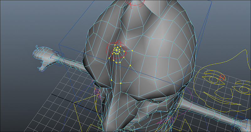
![]() Select the vertices that make up the first spike, as in Figure 12.8.
Select the vertices that make up the first spike, as in Figure 12.8.
![]() Switch to the Animation menu set by pressing F2.
Switch to the Animation menu set by pressing F2.
![]() Click on Create Deformers, Cluster. A “C” will appear in the panel, indicating the cluster is created.
Click on Create Deformers, Cluster. A “C” will appear in the panel, indicating the cluster is created.
![]() Select wobble_CTRL1 and then head_CTRL and parent it by pressing P.
Select wobble_CTRL1 and then head_CTRL and parent it by pressing P.
![]() Select wobble_CTRL1 again and open the Connection Editor by clicking Window, General Editors, Connection Editor.
Select wobble_CTRL1 again and open the Connection Editor by clicking Window, General Editors, Connection Editor.
![]() Note that wobble_CTRL1 is loaded into the left panel already. Now select the cluster that was created and in the Connection Editor, click Reload Right.
Note that wobble_CTRL1 is loaded into the left panel already. Now select the cluster that was created and in the Connection Editor, click Reload Right.
![]() In the left column, select the “translate” attribute. In the right column, also select the “translate” attribute to connect the translation of the control to the cluster.
In the left column, select the “translate” attribute. In the right column, also select the “translate” attribute to connect the translation of the control to the cluster.
![]() The last thing we need to do is make sure the deformation order is correct. Rotate head_CTRL and then select and move wobble_CTRL1 and see the result. As you can see in Figure 12.9, the results are not what we are going for.
The last thing we need to do is make sure the deformation order is correct. Rotate head_CTRL and then select and move wobble_CTRL1 and see the result. As you can see in Figure 12.9, the results are not what we are going for.

FIGURE 12.9 Because the cluster is after the skin deformer, Maya is moving the vertices in the spike in the wrong direction when we adjust the controller. We want the evaluation of the cluster to happen before the skin deformer so that the spike moves in a predictable way.
![]() Undo these movements or return the transformations and rotations of wobble_CTRL1 and head_CTRL to zero.
Undo these movements or return the transformations and rotations of wobble_CTRL1 and head_CTRL to zero.
![]() RMB click and hold on Sam’s geometry until the marking menu appears. In the center-bottom column that appears, click on Inputs, All Inputs.
RMB click and hold on Sam’s geometry until the marking menu appears. In the center-bottom column that appears, click on Inputs, All Inputs.
![]() This menu shows you all of the inputs on a node. As you can see, the Cluster deformer is above the Skin deformer. We want it below. To do that, MMB click and drag the Cluster node on top of the Skin Cluster node. They should switch order.
This menu shows you all of the inputs on a node. As you can see, the Cluster deformer is above the Skin deformer. We want it below. To do that, MMB click and drag the Cluster node on top of the Skin Cluster node. They should switch order.
![]() Repeat the test of the rotation of the head and the transformation of the wobble control. It should move predictably now. To get just a little bit cleaner falloff on the cluster that affects the spike, we are going to smooth the cluster weights. Click on Edit Deformers, Paint Cluster Weights Tool.
Repeat the test of the rotation of the head and the transformation of the wobble control. It should move predictably now. To get just a little bit cleaner falloff on the cluster that affects the spike, we are going to smooth the cluster weights. Click on Edit Deformers, Paint Cluster Weights Tool.
![]() This tool is exactly like the Paint Skin Weights tool, so you should be familiar with it.
This tool is exactly like the Paint Skin Weights tool, so you should be familiar with it.
![]() Use the tool to smooth the influence at the bottom of the spike, like in Figure 12.10.
Use the tool to smooth the influence at the bottom of the spike, like in Figure 12.10.
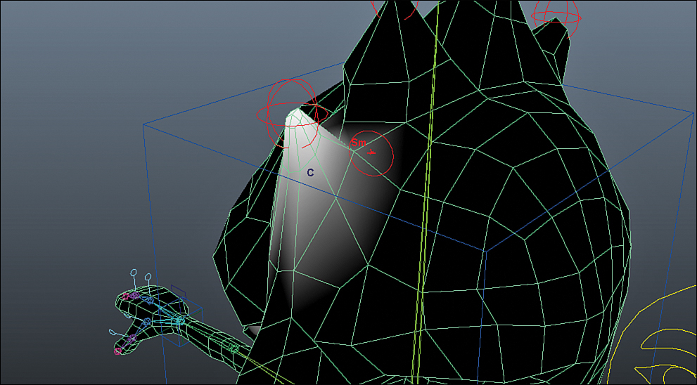
FIGURE 12.10 By default, all the vertices of a cluster made from selected geometry will have a weight of 1. We used the Paint Cluster Weights tool to smooth out these weights to give us a more appealing shape when animating wobble_CTRL.
![]() Repeat all of these steps for each one of the spikes until all five have their own controller.
Repeat all of these steps for each one of the spikes until all five have their own controller.
![]() When you are finished, put all of the clusters into the group sam_DNT_GRP.
When you are finished, put all of the clusters into the group sam_DNT_GRP.
Maya’s deformations are limitless. Because you are only bound by your imagination, sometimes it is best to see what kinds of deformation you need in animation before you get too carried away adding bells and whistles to a rig. There are issues of unnecessarily slowing down your scene by adding many layers of deformation that may never been used by an animator. We’re going to leave off here with the deformation for now; maybe more control will be needed in the future.
Summary
We first took a look at Rigid Bind to see how geometry is deformed by a bone in a rigid way. This type of skinning is useful for solid objects that may need other deformations added on top of them. Even automobiles make use of rigid binds, and they are universally compatible with game engines. Deformation order is an issue with skinning, so we took a brief look at the way that the order of deforming a mesh seriously impacts the outcome. We then added a Smooth Bind to Sam, finally skinning his geometry to the rig we’ve worked so hard on. The default skin weights are almost always mediocre, so our job as artists is to fix the weights by using the Paint Skin Weights tool. After you painted the weights and tested the rig in different poses to affirm your weights, we added more deformations to the character. These clusters were added after the skin cluster node, so we had to reorder each cluster node in the “inputs” menu each time we created one. When that was done, the new deformation order had our wobble controls working perfectly.
Q&A
Q. I’m having a lot of trouble painting weights on the character. Is there any easier way?
A. It’s a time-intensive process. Although it is possible to type in weights on vertices, and although a host of skinning scripts are out there that can speed up the process, skinning will always be laborious. Practice makes perfect.
Q. My model deforms oddly when I move the controls. Any tips for smoothing the deformations?
A. It is always a good idea to move the controls into very extreme poses to exacerbate any weighting issues you are having. For instance, stretch spine3_CTRL way up, down, side to side, and then move the arm controls around. If you see small areas that are “tweaking” when you move the arms, it means you have to continue to paint weights.
Q. I see the null joints in the list of influences. Why?
A. When you applied the Smooth Bind, you had Joint Hierarchy selected to apply the skin to and not Selected Joints. Go back to that step and make sure you copy my settings as in Figure 12.4.
Q. Can I apply any deformer to the model?
A. Yes, you are not limited in what kinds of deformation you add to the model. You could add a Squash deform to the body or a Twist to the head.
Workshop
The workshop contains quiz questions and exercises to help you solidify your understanding of the material covered. Try to answer all questions before looking at the “Answers” section that follows.
Quiz
1. How can you tell if geometry is transforming or deforming?
2. Which form of bind is used for inorganic objects such as robot arms and cars?
3. What key can you press to switch the current paint operation to Smooth?
4. When you’re painting weights, there is an add operation but no subtract operation. Which operation do you use to remove weight from a vertex?
5. How do you access the menu that allows you to reorder deformations?
Exercise
Continue practicing painting weights and creating smooth deformation in a rig. Open up sam_Rig_v2_Final.ma and see if you can get your skin weights as smooth as this file. Try to create a simple rig for other objects using the skills learned in Hour 11, “Character Rigging: Articulating Characters,” and then skin them smoothly. The original sam_Rig we created in Hour 11 can be used for practice as well, because the skeleton is much simpler than v2.
Answers
1. Geometry that is transforming can be seen as doing so because its position (pivot) moves as it is being transformed. Geometry that is being deformed stays in place while the vertices move within the transform node.
2. A Rigid Bind is useful for deforming rigid objects, as opposed to transforming the geometry.
3. The Shift key changes the current operation to smooth. It is useful to adopt a rhythm of painting and smoothing.
4. The Scale operation is the equivalent of subtract, in that it reduces the weight on the painted vertices by scaling the value.
5. The inputs menu is accessed most easily by RMB clicking and holding until a marking menu appears. Click on Inputs, All Inputs to access the deformers and reorder them as needed.