
The road to mastery will always include reinforcement of fundamental skills. Just as an accomplished musician will always practice her scales, we will review the fundamental selection and editing tools throughout the Revit Architecture program. There are many tools in Revit that can assist you in refining your models and project designs. Some are simple geometry editing functions whereas others possess more powerful capabilities. In this chapter, we'll review these tools and provide some exercises for you to remain productive.
In this chapter, you'll learn to:
Select, modify, and replace elements
Edit elements interactively
Use other editing tools
Knowing how to efficiently select, modify, and replace elements is fundamental to working productively in Revit. These interface operations are the foundation upon which you will build skills in creating and editing your project models. In this section, we will review methods for selection, filtering, and modifying properties.
Revit was one of the first programs that had the ability to highlight elements as you hovered the mouse pointer over them before you actually selected them. Not only does this give you a clear idea of what you are about to select, it displays information about that object in the status bar and in a banner near the mouse pointer. When you hover over an element, it highlights (turns purple); click the highlighted element and it turns blue, indicating that it is selected.
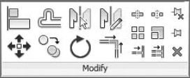
Once an element is selected, the ribbon changes to Modify mode where consistent editing tools are located in the left side and context-sensitive tools will appear to the right. Notice the subtle differences in the ribbon, as shown in Figure 3.1 when a roof, stacked wall, and floor are selected.

You can select elements in many different ways:
- Add or Subtract
You can build a selection of individual elements by using the Ctrl and Shift keys on your keyboard. Hold down the Ctrl key while picking to add elements, and hold down the Shift key while picking to remove elements. Notice the mouse pointer will indicate a plus (+) when you hold the Ctrl key and a minus (-) when you hold the Shift key.
- Window
To select large amounts of elements in a view window, you can click and drag the mouse to form two different types of selection windows. Click and drag from left to right, and only the elements completely within the window will be selected—this implied window is displayed as a solid line. Click and drag from right to left, and any element within or crossing the window will be selected—this implied window is displayed as a dashed line.
- Chain
Although there are no polylines in Revit as there are in AutoCAD, chain-select is an intelligent method for selecting connected elements. To activate this mode, hover your mouse over (but don't click yet) one wall that is connected to several other walls. While the element is pre-highlighted, press the Tab key once, and the connected elements should be selected. When selecting objects, note that the Tab key is used to cycle through all available objects near your mouse pointer. If a floor edge happens to be near the edge of a wall you are trying to chain-select, you can skip the chain of walls and select the floor. Be sure to look at the status bar; it will indicate "Chain of walls or lines" when you have selected correctly.
- Selection Count

- Select Previous
A little-known feature allows you to select elements you had previously selected. Either right-click and choose Select Previous from the context menu or press Ctrl and the left arrow key on your keyboard.
Once you have elements selected, you can filter the selection by object categories using the Filter tool. This tool allows you to select large amounts of elements and then focus your selection by removing categories you don't need, as shown in Figure 3.2. For example, if you box-select an entire floor plan, you will have a selection set of many different categories. Using the Filter tool, you can limit the selection to just the Doors category—or perhaps Doors and Door Tags.
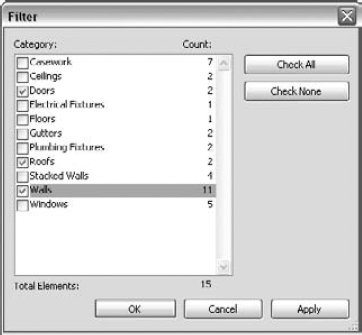
Note that the Filter tool in the ribbon appears only if you have elements from multiple categories selected. If you have elements of only one category selected, you can still open the Filter tool by clicking the Filter icon in the status bar. You can use the Properties Palette as a filter as well; see "Using the Properties Palette" for more information.
Another fast and powerful method for selecting objects is the Select All Instances function. When you right-click a single object in the drawing area or right-click a family in the Project Browser, the Select All Instances tool gives you two options: Visible In View or In Entire Project. Selecting the Visible In View option will select only those items you can see in the current view. This will not select elements that have been either temporarily or permanently hidden in the view.
Use the In Entire Project option carefully because you can modify elements in many places that you did not intend to change. Always remember to look at the selection count in the status bar when you use Select All Instances. Here are some common situations where you might use this tool:
View titles—when updating graphics
Walls—when switching from generic to specific types
Title blocks—moving from design to detail documents
Viewports—useful when trying to purge unused viewports
Note that Select All Instances does not work on model lines or symbolic lines. This limitation exists because lines are not only drawn in project views; they are integral parts of other objects such as filled regions and shaft openings.
Note
The Properties Palette is similar to the Instance Properties dialog box in previous versions of Revit. In the latest version, it is a floating palette that can remain open while you work within the model. The palette can be docked on either side of your screen, or it can be moved to a second monitor. Open the Properties Palette by:
Clicking the Properties icon in the Properties panel of the Modify tab in the ribbon
Selecting Properties from the right-click context menu
Pressing Ctrl+1 on your keyboard (like in AutoCAD)
As shown in Figure 3.3, the Properties Palette now contains the Type Selector at the top of the palette. When placing elements or swapping types of elements you've already placed in the model, the palette must be open to access the Type Selector.
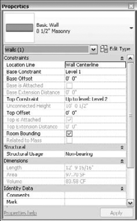
Figure 3.3. The new Properties Palette contains the Type Selector and is used to set View Properties.
When no elements are selected, the Properties Palette displays the properties of the active view. This supersedes the View Properties command in older versions of Revit. If you need to change settings for the current view, simply make the changes in the Properties Palette, and the view will be updated. For views, you may not even need to use the Apply button to submit the changes.
Finally, you can also use the Properties Palette as a filtering method for selected elements. When you select a large number of disparate objects, the drop-down list below the Type Selector will display the total number of selected elements. Open the list and you will see the elements listed per category, as shown in Figure 3.4. Select one of the categories to modify the parameters for the respective elements. This is different from the Filter tool in that the entire selection set is maintained, allowing you to perform multiple modifying actions without reselecting elements.

Be careful when using this tool with walls, because not only does it change the wall type, but it also changes the top and bottom constraints of the walls being matched. Thus, the best practice for changing wall types without affecting height constraints is to simply use the Type Selector.
The context menu that appears when you right-click in the drawing area contains several new options in Revit Architecture 2011. You can activate the last command or select from a list of recent commands, as shown in Figure 3.5.
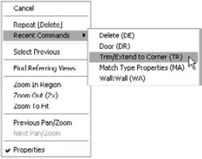
In addition to the other right-click commands listed throughout this chapter (such as Create Similar), zoom commands including Previous View are on the context menu. There are also useful commands when you right-click views in the Project Browser. For example, activate a plan view and then try right-clicking a 3D view in the browser. Select Show Section Box, and you can edit the extent of the 3D view's section box while in a floor plan.
Revit provides a range of options to interactively edit elements in the model. The most obvious is to select elements to drag on the screen or use the blue control grips to extend walls, lines, shape faces, and region boundaries; however, you often need more precise ways of moving and copying objects. Let's look at some ways to do this.
You can move elements in several ways, ranging from traditional tools to using intelligent dimensions that appear on the fly when you select elements. Become familiar with each method and determine what is best for your workflow.
You have likely noticed by now that dimensions appear when elements are selected or newly modeled in Revit. These dimensions are called temporary dimensions and are there to inform you of the location of the elements relative to other elements in the model as well as to help you reposition them. Clicking the blue dimension value makes it an active and editable value. Type in a new value, and the selected element will move accordingly. Remember that when you are editing the position of an element via the dimensions, it will always be the selected element that moves. You can't change a dimension value if nothing is selected.
If a temporary dimension isn't referencing a meaningful element, you can choose a different reference by dragging the small blue square on the dimension's witness line to a new parallel reference, which will highlight when the mouse moves over them (Figure 3.6). For example, if you want to position a door opening at a specific dimension from a nearby wall, you will need to drag the grip of the temporary dimension that references the center of the door to the side of the opening. Then you can edit the value of the dimension as required. When you are dragging the grip of a temporary dimension, you can also use the Tab key on the keyboard to cycle through available snapping references near the mouse pointer.

If you click a blue grip, it cycles to the next possible reference in the element. For example, clicking the grip of a dimension to a door or window cycles between the left and right openings and the center reference. The same applies to walls: try clicking the grip on the temporary dimension extending from a wall and see how the dimension cycles through the various references in the wall (interior face, centerline, exterior face). Note that when you drag a temporary dimension reference to a different position, the new reference is remembered when you return to the element for future editing.
You can also change the default behavior of temporary dimensions using the Temporary Dimension Properties dialog box shown in Figure 3.7 (on the Manage tab, click Additional Settings and then select Temporary Dimensions). Here you can specify how temporary dimensions will reference walls, doors, and windows independently.
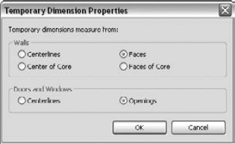
Figure 3.7. The Temporary Dimension Properties dialog box lets you define default behaviors based on your modeling needs.
You can now modify the font size and transparency of temporary dimensions in the program options. To customize these values, click the Application button and select Options. In the Options dialog box that opens, switch to the Graphics tab and locate the Temporary Dimension Text Appearance settings. Adjust the text size and transparency according to your needs.
If you have many elements selected at the same time or select an element within the proximity of a large number of other elements, temporary dimensions sometimes don't appear. Check the Options Bar for the Activate Dimensions button; clicking it will make the temporary dimensions appear in the view.
New Behaviors for Modify Tools
In Revit Architecture 2011, the Modify tools behave differently than in previous versions. Now you have the option to activate the tools without any elements selected. If you choose this method, you must press the Enter key when the objects you intend to modify are selected.
You can also switch between any of the Modify panel tools while you have elements selected. For example, if you initially chose Mirror – Pick Axis and selected an element during the command, you can simply activate the Mirror – Draw Axis command without reselecting the elements.
Note
Use the Move tool to relocate elements with more precision than by simply dragging them. The tool allows you to type in values or use temporary dimensions as helpers.
Moving elements is a two-click process: first you define a start point, and then you click to define a destination. If you know you need to move something a specific distance, it doesn't matter where your two picks take place. All that matters is the distance between the two clicks is the specified distance. Alternatively, you can simply type the desired value after picking the first point and guiding the mouse pointer in the desired direction of the move. This behavior is similar to the move command in AutoCAD.
There are a few options on the Options Bar to be aware of when the Move command is active:
- Constrain
When this option is selected, it constrains movements to horizontal and vertical directions. Deselecting it allows you to move the elements freely as long as the element is not hosted. Hosted elements such as windows or doors always move in a constrained manner parallel to their host's axis.
- Disjoin
Hosted elements can't change hosts and move to another host without being explicitly disjoined from their original host. This option lets you disconnect inserts from their hosts and move them to new hosts. For example, if you need to move a door from one wall to another, select the door and activate the Move tool. Select the Disjoin option and move the door to another host. Similarly, you can use the Disjoin option to move one wall away from another without maintaining the join between the two elements.
- Multiple
The Multiple option is not active for the Move tool. This option is only available when you switch to the Copy tool.
Nudging is a simple way to push things around quickly, as you would in software programs such as Microsoft Office. When elements are selected, you can use the arrow keys on the keyboard to move the elements horizontally or vertically in small increments. Each press of an arrow key nudges the element a specific distance based on your current zoom factor. The closer you zoom, the finer the nudge is. Note that your snap settings do not affect the nudging distances set by the zoom level.
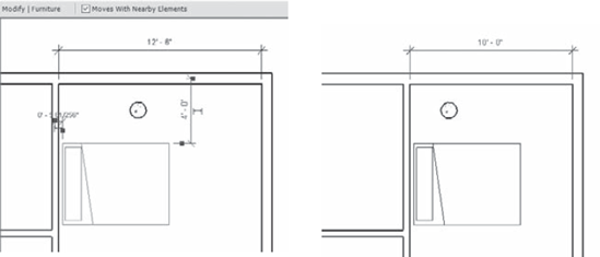
A simpler way to constrain freestanding elements is to use the Moves With Nearby Elements option. This setting is designed to capture logical relationships between elements without establishing an explicit constraint. When furnishing a space, for example, you probably want to align the bed or dresser with an adjacent wall. If you change the design of the space, you want the furniture to follow the wall to the new location. For this purpose, select the furniture and then select Moves With Nearby Elements in the Options Bar, as shown in Figure 3.8.
By setting this option, you create an invisible relationship between the bed and the wall so that each time you move the wall, the bed moves with it. To clarify the difference between this approach and other constraint relationships, you could create a wall-hosted family, but that would limit your placement options and would subject instances to deletion if the host is deleted. You could align and constrain the family to its host, but too many explicit constraints will adversely affect model performance.
Note
The Copy tool is another modifying tool that is nearly identical to the Move tool but makes a copy of the selected element at the location of the second pick. This tool doesn't copy anything to the clipboard; it copies an instance of an element or selection of elements in the same view. If you change views while using this tool, your selection is lost.
To activate this tool, either choose elements you want to copy and then select the Copy tool in the Modify tab in the ribbon, or activate the Copy tool first, select elements you want to copy, and then press the Enter key to start the copy process. Using the Options Bar, you can choose to make multiple copies in one transaction by selecting the Multiple option.
An alternative to the Copy tool is to use standard Windows accelerator keys to copy elements. To quickly copy a single element without the precision of the Copy tool, click and drag on an element while pressing the Ctrl key on your keyboard. This technique is useful for quickly populating a quantity of elements in a design without the required precision of the multiple picks of the Copy tool.
Note
When refining or expanding your building design, you will likely find a frequent need to rotate or mirror one or more objects. Just as with moving or copying, Revit provides a few methods for these types of interactive operations. The quickest way to rotate elements in 90-degree increments is by pressing the spacebar on your keyboard. For more precision, you can use the Rotate tool to rotate elements to any specific angle you require.
You can use the spacebar to rotate elements both at the time of placement and after an element has been placed. In addition to rotating an object through 90-degree increments, pressing the spacebar will locate any nearby diagonal references (walls, grids, or reference planes) as rotation candidates. This is a great timesaving command to become familiar with because you can forgo the necessity of using an additional tool such as Rotate and Mirror after placing an object. Here are a few examples:
- Doors and Windows
If you have a door with its swing in the wrong direction, select it and press the spacebar. You can cycle through all four possible orientations of the door using the spacebar. The same holds true for windows; however, many window families are built to only let you flip the window from inside to outside because many windows are symmetrical in elevation. If you are creating an asymmetrical window family, be sure to add flip controls to the window family during its creation. These controls allow the spacebar to work on hosted elements.
- Walls
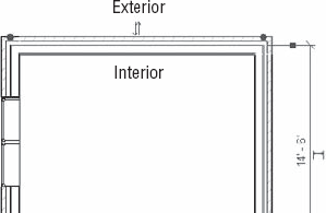
If you select a wall, pressing the spacebar flips the element as if it were being mirrored about its length. Walls flip based on the wall's Location Line, which often isn't the centerline of the assembly. If you aren't sure which direction your wall is facing, select it and look for the flip-control arrows. These are always located on the exterior side of walls (Figure 3.9).
- Freestanding Elements
If you select a freestanding element, the spacebar rotates the element about the center reference planes defined in the family. Depending on how the family was built, the rotation origin may not make the most sense. If you decide to edit a family to change the location of the geometry relative to the center reference planes, be careful: when the family is loaded back into a project, all instances of the family will jump to a new location based on the change you made relative to the reference planes.
Note
To rotate an element, select it and click the Rotate tool. Remember, you can also activate the Rotate tool first, select one or more elements, and then press Enter to begin the operation. This is a two-click operation similar to the Move and Copy tools. Alternatively, you can enter numeric values for the desired rotation angle. Revit locates the geometric center of the selected elements and uses that as the default center of rotation; however, you will most likely want to designate a more meaningful center.
To choose a new center of rotation, select and drag the center icon to a new location before clicking to set the starting reference angle. Note that you might have to zoom out in order to find the center icon. Once the center is established, begin rotating the element using the temporary dimensions as a reference or by typing in the angle of rotation explicitly.
You'll notice that while moving the center of rotation, you lose the ability to pan and zoom the view. To overcome this, drag the center into the Project Browser and release the mouse button; then, move the mouse pointer back into the view. The mouse pointer changes to a rotation icon, and you can freely zoom and pan to the desired location. The next click you make places the origin and you can continue with the rotation operation. Note that you can also use keyboard snap shortcuts to refine the location of the center of rotation while dragging it. For example, type SE to snap to an explicit endpoint while dragging.
Note
The Mirror tool allows you to mirror elements across an axis in order to create a mirror image of an element or multiple elements. You can either pick an existing reference in the model with the Mirror – Pick Axis tool or draw the axis interactively using the Mirror – Draw Axis tool. In Figure 3.10, the centerline of the plumbing chase wall was picked as the axis for mirroring the plumbing fixtures.

Figure 3.10. The sink, toilet, and bath fixtures are mirrored about the centerline of the chase wall.
As with the other modify tools you have seen so far, the Mirror tools have the option to create a copy of the selected elements or to simply mirror the selected elements to a new position. You can find the Copy option in the Options Bar after you activate either of the mirror tools.
Note
An array allows you to copy instances of an element with equal spacing between the instances. Revit provides the option to create intelligent arrays that can be grouped and associated for further refinement as well as one-off, unassociated arrays. Like the other tools we've reviewed in the Modify tab of the ribbon, the array options are presented on the Options Bar.
You can create two types of arrays: linear and radial. Linear arrays are set as the default because they're the most common. As you would expect, a linear array creates a series of elements in a line. Each element in the array can be given a defined distance from the previous element (Move To 2nd option) or can be spaced equally based on a defined overall array length (Move To Last option). Figure 3.11 shows a linear array where the Move To 2nd option was selected in order to define a fixed distance between each instance in the array. Think of this type of array as additive and subtractive: if you change the number, the length of the array increases or decreases.

Figure 3.11. The Move To 2nd option is used in the Array tool to set a fixed distance between instances.
If you want to arrange elements in a fixed space and the exact spacing between elements is less important, use the Move To Last option. Figure 3.12 shows an array where the location of the last element in the array was picked and the elements were placed equally between the first and last elements in the array. With this option, the length is fixed and the array squeezes elements within that constraint as the number changes.

Figure 3.12. This array uses the Move To Last option and fills instances between the first and last instances.
A radial array uses the same options as a linear array, but it revolves around a center point. The Move To 2nd and Move To Last options function as angles instead of distances in a radial array. You can specify the instance angle or overall array angle with two picks or you can enter a specific value. With this type of array, elements autorotate so that each element faces the center of the array, as shown in Figure 3.13.

The radial array is a little trickier than a linear array. Here is how to achieve the example shown in Figure 3.13:
Before starting the radial array, draw a detail line to help locate the intended center of the array.
Select the element and activate the Array tool from the Modify tab in the ribbon. Select the Radial option button, change the Number to 6, and choose the Move To Last option.
Drag the center of rotation off the element and to the endpoint of the detail line you drew in step 1.
Click the mouse to define any starting point. An exact starting point is not important because you will be defining a complete circle in the next step.
Do not click a second time; instead, go to the Options Bar, type 360 in the Angle option, and press Enter on the keyboard.
Enabling the Group And Associate option allows you to treat an array as a group that can be modified later to adjust the number and spacing of the array. If this option is unchecked, then the array is a one-off operation and you have no means of adjusting the array after it is created.
As shown in Figures 3.11 and 3.12, when an element in a grouped array is selected, a control appears indicating the number of elements in the array. Editing that number changes the number of elements in the array. This tool comes in handy when you're creating certain families because the array number can be associated with a parameter or driven by a mathematical formula. See Chapter 15 for a detailed exercise.
The Scale tool lets you scale certain lines and graphic elements in 2D that are appropriate to be scaled, such as imported raster images and 2D line shapes. While not an obvious option, the Scale tool can be used in Sketch mode for any type of sketch-based element in a project or for solid and void geometry sketches in the Family Editor.
Keep in mind that you are working with a model made out of real-world objects, not abstract primitive forms. You cannot scale most elements in Revit because it's not practical or meaningful and may cause dangerous errors in scheduling and dimensions. For example, you can't scale the size of a door, wall, or sink because they represent real assemblies and scaling them would mean resizing all their components. This would lead to impractical results, such as a sink being displayed as a fraction of its actual manufactured size.
Note
If you've been using Revit for any amount of time, you have likely discovered the power of the Align tool. It has the ability to supplant the need to use many of the tools we've already discussed. The Align tool lets you line elements up in an efficient way that works on almost all types of objects.
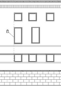
With this tool, you explicitly align references from one element to another regardless of the type of either object. For example, you can align windows in a façade so their centers or openings are all in alignment. To use the Align tool, activate it from the Modify tab in the ribbon and first select the target reference—a reference to which you want to align another element. Next, select what you want to align to that reference—the part or side of the element whose position needs to be modified. The second element picked is the one that always moves into alignment. This selection sequence is the opposite of the other editing tools we've discussed so far, so remember: destination first, then the element to be aligned.
As soon as you make your second pick and the aligned element is moved, a lock icon appears allowing you to constrain the alignment. If you click the icon, thereby constraining the alignment, the alignment is preserved if either element moves. Figure 3.14 illustrates the use of the Align tool to align multiple windows in an elevation view using the Multiple Alignment option on the Options Bar.
The Align tool also works within model patterns such as brick or stone on surfaces of model objects. Select a line on an object such as the edge of a wall then select a line in the surface pattern. Use the Tab key if you cannot get surface patterns selected with the first mouse click. Note that the Align tool will also rotate elements in the process of aligning them to objects which are not parallel. This is a real time-saver compared to moving and rotating.
Note
You can trim and extend lines and walls to one another using the Trim/Extend tools on the Modify tab of the ribbon. In older versions of Revit, this function was assigned to a single button with three options in the Options Bar. In the latest version, there are three separate tools in the ribbon: Trim/Extend To Corner, Trim/Extend Single Element, and Trim/Extend Multiple Elements. With the Trim/Extend tools, you first activate the tool and then operate on elements in the model, selecting two lines or walls that need to meet in a corner or as a T intersection.
The Trim/Extend tools are used frequently for editing sketches of floors and roofs because it's easy to end up with overlapping lines that need to be trimmed to form a closed loop. Keep in mind that with the Trim/Extend tools, you are selecting pairs of elements to remain, not to be removed. While the Single Element and Multiple Elements tools are similar to the Extend command in AutoCAD, the behavior of the Trim/Extend To Corner tool in Revit is more like that of the Chamfer or Fillet commands, rather than its Trim command.
The Trim/Extend tools for extending a single element or multiple elements function in a slightly different way than Trim/Extend To Corner. To extend a wall or line, first select a target reference; then select the element you want to extend to that target (Figure 3.15). Using the Multiple Elements tool, you first select the target reference; then each subsequent pick extends the selected element to the target reference.
The Split tool operates on walls and lines and lets you divide an element into two pieces. To cut an element, activate the Split tool from the Modify tab in the ribbon and place the mouse pointer over the edge of a wall or line. Before you click, you'll see a preview of the split line. The split line will automatically snap to any adjoining geometry.
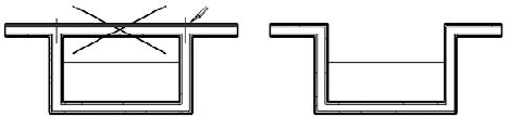
The Options Bar displays a nice feature called Delete Inner Segment that removes the need to use the Trim tool after a splitting operation. In Figure 3.16, you need to remove the middle section of a wall and end up with a clean set of wall joins. Using the Split tool with the Delete Inner Segment option checked, you can accomplish this with two clicks and get a clean condition without having to return with the Trim command.
A new feature has been added to Revit 2011 that extends the functionality of the Split tool. The Split With Gap tool allows you to specify a gap distance and pick a single point on a wall. Although the wall is divided into two separate segments, the gap distance is maintained with an automatic constraint. To use Split With Gap, follow these steps:
Go to the Modify tab and from the Modify panel, select Split With Gap.
Specify the Joint Gap distance in the Options Bar. Note that this distance can only be set between 1/16"[1.6 mm] and 1'-0"[304.8 mm].
Move the mouse pointer over a wall and click to place the gap.
Once you have successfully split a wall with a gap, select the wall and notice the constraints (locks) on the gap and between the two parallel wall segments. Try to drag either of the wall ends separated by the gap and you will see the gap distance is maintained. Try to move the wall in a direction perpendicular to the wall segments and you will notice the two wall segments remain aligned.
If you'd like to rejoin walls that have been split with a gap, follow these steps:
Select a wall split with a defined gap.
Click the constraint icon in the gap to unlock the dimension constraint.
Right-click the end grip of one wall segment and select Allow Join.
Select the other wall and repeat step 3.
Drag the wall end grip of one wall segment to the end of the other segment. The walls should join.
Note that on walls with smaller gaps, the segments may automatically join as soon as you select Allow Join; however, rejoined segments may not form a single segment. If you have trouble joining two parallel wall segments into one, try to drag one of the wall ends away from the other and release the mouse button; then drag the segment back to the other end.
Note
Offset is similar to the Move and Copy tools in that it moves and makes a copy of an element by offsetting it parallel to an edge you select. You can find the Offset tool in the Modify tab of the ribbon. You can also specify an offset distance as an option in the Options Bar when you are sketching lines or walls.
This tool is especially useful in the Family Editor when you're making shapes that have a consistent thickness in profile, such as extruded steel shapes. The Offset tool has a Copy option available in the Options Bar that determines whether the offsetting operation generates a copy of the selected elements or simply moves them.
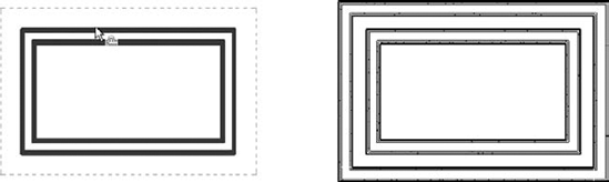
Remember that you can Tab-select a chain of elements and offset them in one click, as shown in Figure 3.17.
In some cases, you may want to make sure some elements in the model never move. An example of this is when you work on a renovation to an existing building. For obvious reasons, you would not like to move walls in the model that are already built in reality. Other examples include imported drawings, grids, levels, and exterior walls. Revit provides two ways to deal with this and lock certain elements, thus preventing them from moving.
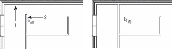
You can restrict an element's ability to move by pinning it with the Pin tool. Use this tool to lock down critical elements that need to remain fixed for long periods of time. This is an important tool to use on imported CAD files, because it's easy to accidentally select an import and drag it or move it. This kind of accidental modification can lead to coordination problems, even in a BIM environment. Use pins to lock down gridlines as well, because you certainly don't want those to move accidentally either.
This tool is located in the Modify panel of the Modify tab in the ribbon. Select one or more elements for which you want to prevent movement and click the Pin tool. If you try to move the element, nothing will happen—you won't even get a preview of a potential move. To unpin an element, select it and click the Unpin icon, which is also located in the Modify panel. You can also unpin an element by clicking the pin icon that appears near a pinned element when it is selected.
Constraints aren't as rigid as the Pin tool, but they do allow you to create dimensional rules in the model so that elements remain fixed relative to other elements. You can create a constraint using dimensions or alignments and then click the lock icon that appears upon creation of a dimension or completion of an alignment operation.
A simple example of using constraints is maintaining a fixed distance between a door and a side wall. If the wall moves, the door will also move. If you try to move the door, Revit will not let you move it. Look at Figure 3.18: the door has been constrained to remain 4"from the wall face.
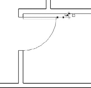
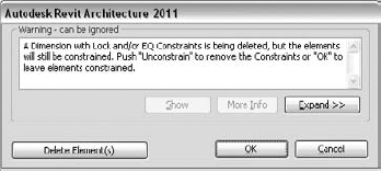
This type of constraint is accomplished by placing a dimension string between the side of the door and the face of the wall and then clicking the lock icon on the dimension. Note that the dimension can be deleted while preserving the constraint. If you delete a constrained dimension, an alert will appear giving you the option to unconstrain the elements or simply delete the dimension while maintaining the constraint (Figure 3.19). Note that you can determine where constraints were by creating new dimensions; constrained relationships will still display with the lock icon. You can also view these relationships when a constrained element is selected. Simply hover the mouse pointer near the constraint icon and you will see the dimension constraint represented as a dashed dimension string.
A range of other editing tools are available in Revit, and we'll cover them in subsequent chapters when they're used in specific operations; however, there are a few tools you should know about now because they are generic tools you can put to immediate use on any project.
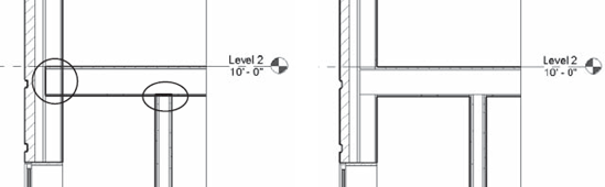
Joining walls to floors and roofs creates cleaner-looking drawings, and Revit will attempt to create these joins automatically; however, in some cases, elements don't look right until they are explicitly joined. This is where the Join Geometry tool comes into play. This tool creates joins between floors, walls, ceilings, roofs, and slabs. A common use for this tool is in building sections, where floors and walls may appear overlapped and not joined. Figure 3.20 shows a floor intersecting with some walls that aren't joined. Using the Join Geometry tool, these conditions can be cleaned up nicely.
You might notice that some joins—especially in a view set to coarse detail level—contain a thin dividing line between two elements. This is usually because the two elements you joined consist of differing materials. Ensuring consistent material application will give you increased graphic quality in your project views.
You should also be aware that joining large host elements to many other elements may cause degraded model performance. One way to avoid this is to apply a black solid fill to elements in the cut plane of your coarse sections and avoid overall manual joining; then selectively join for medium and fine views.
Occasionally you may need to apply a thin material to the face of an object without making a new type of element. You may also need to divide an overall surface into smaller regions to receive different materials. Revit provides the Paint tool to apply materials and the Split Face tool to divide object surfaces. With the Paint tool, you can apply alternative materials to the exterior faces of walls, floors, roofs, and ceilings. This material has no thickness, but you can schedule it with a material takeoff schedule and annotate it with a material tag. A typical use case for these two tools is the application of a carpet or thin tile to a floor. See Chapter 14, "Floors, Ceilings, and Roofs," for a detailed exercise on this topic.
Copying and pasting is a familiar technique used in almost all software applications, and Revit provides the basic features you'd expect (Ctrl+C and Ctrl+V). It also has some additional timesaving options that are specific to working on a 3D model.
To copy any element or group of elements to the clipboard, select them and press Ctrl+C. To paste, press Ctrl+V. In the majority of cases, Revit pastes the elements with a dashed bounding box around them. You then determine where to place the elements by clicking a point to define its final position. In the Options Bar you will find a Constrain option that when clicked will only let you define the location of the pasted content orthogonally to the original elements.
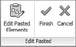
Immediately after you select a point for the location of the pasted content, you will find a new panel in the ribbon called Edit Pasted (Figure 3.21). You can click Finish to complete the pasting action or simply start another command. If you are unsatisfied with the pasting action, select Cancel.
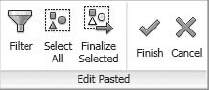
If you select Edit Pasted Elements, a special mode will be started with the Edit Pasted tools appearing at the top left of the active window (Figure 3.22). In this mode, only the pasted elements are editable. You can use the Select All or Filter button to refine those elements within the pasted selection. When your edits are completed, click the Finish button.
If you need to paste elements with greater location control, Paste Aligned offers options to make the process simple and efficient. These options allow you to quickly duplicate elements from one view or one level to another while maintaining a consistent location in the X-Y coordinate plane. After selecting elements and copying them to the clipboard, find the Paste button in the Clipboard panel, as shown in Figure 3.23.
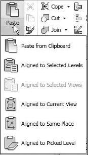
Five options are available when you click the Paste drop-down button, in addition to the Paste From Clipboard option. Depending on the view from which you copy and what kinds of elements you copy, the availability of these options will change. For example, if you select a model element in a plan view, you won't have the Aligned To Selected Views option. These options are as follows:
- Aligned To Selected
Levels This is a mode you can use to quickly paste copied elements to many different levels simultaneously. When you select this option, you choose levels from a list in a dialog box. This is useful when you have a multistory building design and you want to copy a furniture layout that repeats on many floors and selecting level graphics in a section or elevation would be too tedious.
- Aligned To Selected Views
If you want to copy view-specific elements such as drafting lines, text, or dimensions, this option allows you to paste them by selecting views from a list of views in a dialog box. In the list available for selection, you don't see levels listed but rather a list of parallel views. For example, if elements are copied from a plan view, all other plan views are listed. Likewise, if you copy from an elevation view, only elevation views are listed.
- Aligned To Current View
This option pastes the elements from the clipboard into the active view, in the same spatial location. For example, if you copy a series of walls in one view, switch to another view in the Project Browser, and choose to paste with the Aligned To Current View option, Revit pastes the walls to the same X-Y location in the view you switched to.
- Aligned To Same Place
This option places elements from the clipboard in the exact same place from which it was copied or cut. One use for this tool is copying elements into a design option; see Chapter 11, "Designing with Design Options and Groups," for an explanation of design options.
- Aligned To Picked Level
This is a mode you can use to copy and paste elements between different floors by picking a level in a section or elevation. Although you can cut or copy elements from a plan view, you must be in an elevation or section to paste using this option. You might use this paste option to copy balconies on a façade from one floor to another.
Rather than hunting through a list of families or making copies you'd have to edit later, try using the Create Similar tool to add new instances of a selected element to your model.
This tool is available in the Create panel of the Modify tab of the ribbon when an object is selected or from the right-click context menu. To use this tool, simply select an existing instance of the same type of element you'd like to create and click the Create Similar tool, and you will immediately be in a placement or creation mode according to the type of element. For example, if you use Create Similar with a floor selected, you're taken directly into Sketch mode, where you can start sketching the boundary for a new floor.
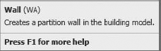
To increase your productivity even further, you may like to use keyboard shortcuts to speed up common commands and minimize interruptions to your workflow. When you hover your mouse pointer over any tool in the ribbon, the keyboard shortcut is indicated to the right of the tool name, as shown here.
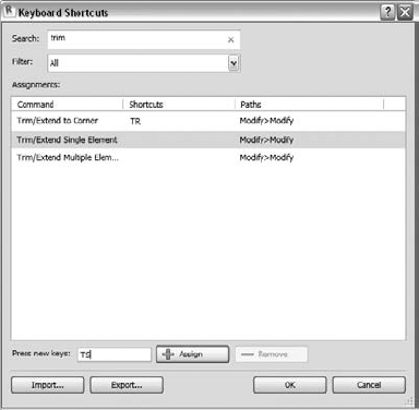
You can customize the keyboard shortcuts assigned to all commands in Revit through a new interface. To access this tool, go to the View tab in the ribbon, find the Windows panel, and select User Interface
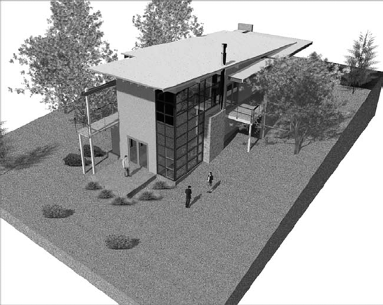
In the previous sections of this chapter, you learned about the fundamental tools for editing and modifying model elements. Another set of tools you should become familiar with are the site tools. These allow you to create a context within which your building models can be situated. For example, a toposurface will create a hatched area when you view your building in a section, and it will function as a hosting surface for site components such as trees, shrubs, parking spaces, accessories, and vehicles (Figure 3.25).
The site tools in Revit are only intended to be used for the creation of basic elements, including topography, property lines, and building pads. Although editing utilities are available to manipulate the site elements, these tools are not meant to be used for civil engineering like the functionality found in Autodesk Civil 3D.
In the following sections you'll learn about the different ways to create and modify a toposurface, how to generate property lines with tags, and how to model a building pad within a toposurface.
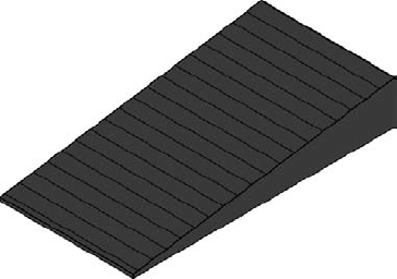
As its name suggests, a toposurface is a surface-based representation of the topography context supporting a project. It is not modeled as a solid in Revit; however, a toposurface will appear as if it were solid in a 3D view with a section box enabled (Figure 3.26).
You can create a toposurface in three different ways: by placing points at specific elevations, by using a linked CAD file with lines or points at varying elevations, or by using a points file generated by a civil engineering application. We'll examine these techniques in the following exercises.
Note
The simplest way to create a toposurface is by placing points in your Revit project at specific elevations. To create a clean outer edge for your toposurface, we suggest drawing a large rectangle using detail lines in your site plan. When you are creating a toposurface by placing points, there are no line-based geometry tools; however, points can be snapped to the detail lines. The following exercise will show you how to create a toposurface by placing points.
Begin by opening the file
c03-Site-Tools.rvt, which can be downloaded from this book's companion website atwww.sybex.com/go/masteringrevit2011.Activate the floor plan named Site and you will see a rectangle created from detail lines.
Go to the Massing & Site tab and from the Model Site panel, click Toposurface. Notice in the contextual tab in the ribbon that the default tool is Place Point.
Notice the Elevation value in the Options Bar. Set the value of the points you are about to place.

Also note that the elevation values are always related to the Revit project base point. They do not relate to the elevation of any shared coordinates.
With the Elevation value set to 0'-0"(0mm), place a point at each of the left corners of the rectangle.
Change the Elevation value to 20'-0"(6000mm) and then place a point at each of the right corners of the rectangle. You will notice the contour lines of the surface begin to appear after the third point of the surface is placed.
In the contextual tab of the ribbon, click Finish Surface (green check) to complete the toposurface. Activate the default 3D view and you will see the sloping surface, as shown in Figure 3.27. Notice that the 3D view in this project already has the Section Box property enabled. To adjust the section box, activate the Reveal Hidden Elements tool in the View Control bar.
Save the project file for use in subsequent exercises.
Note
A common workflow you may encounter involves the use of CAD data generated by a civil engineer. In this case, the engineer must create a file with 3D data. Blocks, circles, or contour polylines must exist in the CAD file at the appropriate elevation to be used in the process of generating a toposurface in Revit.
In the following exercise, you will download a sample DWG file with contour polylines. You must link the file into your Revit project before creating the toposurface.
Create a new Revit project using the
default.rteorDefaultMetric.rtetemplate.Download the file
c03-Site-Link.dwgfrom this book's companion website atwww.sybex.com/go/masteringrevit2011.Activate the Site plan in the Project Browser.
Go to the Insert tab in the ribbon and click the Link CAD button. Select the
c03-Site-Link.dwgfile and set the following options:Current View Only: Unchecked
Import Units: Auto-Detect
Positioning: Auto - Center To Center
Place At: Level 1
Click Open to close the dialog box and complete the insertion of the CAD link. Open a default 3D view to examine the results (Figure 3.28).
From the Massing & Site tab in the ribbon, click the Toposurface button. In the Tools panel of the Modify | Edit Surface ribbon, select Create From Import and then Select Import Instance.
Pick the linked CAD file and the Add Points From Selected Layers dialog box will appear (Figure 3.29). Click the Check None button and then select the layers C-TOPO-MAJR and C-TOPO-MINR.
Click OK to close the dialog box. It may take a few seconds to generate the points based on the contour polylines in the linked file, but they will appear as black squares when they have all been placed.
If you would like to use fewer points to define the toposurface, click the Simplify Surface button in the contextual ribbon and enter a larger value such as 1'-0"(250mm).
Click the Finish Surface button in the contextual ribbon to complete the toposurface. Change the visual style of the view to Consistent Colors to examine your results.

Note
A less common method for creating a toposurface, although equally effective when using linked CAD data, is using a points file. A points file is a text file that is usually generated from a civil engineering program. It must be a comma-delimited file (TXT or CSV format) in which the x, y, and z coordinates of the points are the first numeric values in the file. In the following exercise, we have provided a sample points file that was exported from Autodesk Civil 3D using the XYZ_LIDAR Classification (comma-delimited) format setting.
Open the file
c03-Site-Points.rvt, which can be downloaded from this book's companion website atwww.sybex.com/go/masteringrevit2011.Download the file
c03-Points.csvfrom this book's website to your local computer.Activate the Site plan in the Project Browser.
From the Massing & Site tab in the ribbon, click the Toposurface button. In the Tools panel of the Modify | Edit Surface ribbon, select Create From Import and then choose Specify Points File.
Navigate to the
c03-Points.csvfile and click Open. Note that if you were using a TXT format file, you'd change the Files Of Type option to Comma Delimited Text.In the Format dialog box, select Decimal Feet. It is important to understand the units of the values in the points file to ensure the toposurface will be created at the correct scale. Click OK to close the dialog box.
Click the Finish Surface button in the contextual ribbon to complete the toposurface. Open the default 3D view to examine your results. You may have to use the Zoom All command to see the extents of the new toposurface.
Save the project file for use in subsequent exercises.
In the following sections, you will continue to use this file to explore the tools available for modifying a toposurface.
The points file example we provided in the previous exercise represents a section of terrain across Lake Mead, Nevada. If you wanted to define an area of the toposurface with a different material but not change the geometry of the overall surface, you would use the Subregion tool. In the following exercise, you will use this tool to create a region that will represent the water of the lake.
Using the
c03-Site-Points.rvtfile, activate the Site plan from the Project Browser. In this view, there are dashed detail lines that represent the edge of the water.Go to the Massing & Site tab in the ribbon and click the Subregion tool.
Switch to Pick Lines mode in the Draw panel of the contextual ribbon.
Hover your mouse pointer over one of the dashed detail lines at the left side of the surface, Tab-select the chain of lines, and then click to select them. You will see a purple sketch line appear.
Repeat step 4 for the dashed detail lines at the right side of the surface.
Switch to Line mode in the Draw panel of the contextual ribbon and draw a line connecting each open end of the water edge lines, as shown in Figure 3.30.
Click Finish Surface in the contextual ribbon to complete the subregion.
Activate the default 3D view and select the subregion you created in the previous steps.
In the Properties Palette, locate the Material parameter and click the ellipsis button to open the Materials dialog box. Locate and select the material named Site - Water. Note that you can easily find this material by typing Water in the search field at the top of the dialog box.
Click OK to close the Materials dialog box; you will see the results in the 3D view, as shown in Figure 3.31.

When you use the Subregion tool, the geometry of the original surface remains unchanged. If you no longer need the subregion, you can simply select it and delete it. Be aware that topographic surfaces cannot display surface patterns assigned to materials.

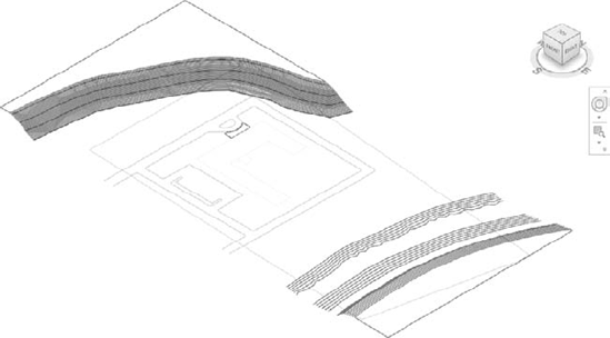
If you need to divide a topographic surface into separate parts for the purpose of editing the geometry, you would use the Split Surface tool. With this tool, you can sketch a single line along which the surface will be divided into two editable entities. These separate entities can be recombined later using the Merge Surfaces tool. In the following exercise, you will split a topographic surface and edit some of the points. Remember that you can also use Split Surface to delete a portion of a topographic surface.
Open the file
c03-Site-Tools.rvtyou saved after the earlier lesson in this section.Activate the Site plan in the Project Browser.
Go to the Massing & Site tab in the ribbon and click the Split Surface tool. Remember that you should use the Subregion tool if you only plan to assign a different material to the split region of the original surface.
Select the topographic surface and you will enter Sketch mode. Using the Line mode in the Draw panel of the contextual ribbon, draw two lines that overlap the edges of the surface, as shown in Figure 3.32.
Click Finish Edit Mode in the ribbon and you will see the split surface highlighted in blue.
Activate the default 3D view and turn off the Section Box option in the Properties Palette.
Select the split surface and click the Edit Surface tool in the Modify | Topography tab of the ribbon.
Select the point at the outer corner of the topographic surface and change the elevation value in the Options Bar from 20'-0"(6000mm) to 10'-0"(3000mm).
Click Finish Surface in the contextual ribbon and you will see the result as shown in Figure 3.33.
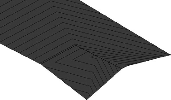
To illustrate the difference between a split surface and other topographic surface edits, select the main surface and click Edit Surface in the contextual ribbon. Select the point at the upper corner opposite from the split region and change the elevation value to 10'-0" (3000mm). Notice the difference in how the surface slope is interpolated between the other points on the surface (Figure 3.34).


A building pad in Revit is a unique model element that resembles a floor. It can have a thickness and compound structure, it is associated with a level, and it can be sloped using slope arrows while you're sketching its boundary. The building pad is different from a floor because it will automatically cut through a toposurface, defining the outline for your building's cellar or basement.
The process to create a building pad is virtually identical to that of creating a floor. Let's run through a quick exercise to create a building pad in a sample project.
Open the file
c03-Site-Pad.rvt, which can be downloaded from this book's website atwww.sybex.com/go/masteringrevit2011.Activate the floor plan named Site in the Project Browser. You will see an existing topographic surface and property line. Notice that reference planes were created to demarcate the required zoning setbacks from the property line. Foundation walls have been created within these reference planes.
Note that you don't have to create a property line and walls before creating a building pad. You might create a building pad before any other building elements. Just realize that you can utilize the Pick Walls mode to associate the boundary of the building pad with the foundation walls.
Activate the Cellar floor plan from the Project Browser.
Go to the Massing & Site tab in the ribbon and click the Building Pad button. In the Properties Palette, change the Height Offset From Level value to 0.
Switch to Pick Walls mode in the Draw panel of the contextual ribbon and then pick the inside edges of the four foundation walls. You can use the Tab-select method to place all four lines at once.
Click the Finish Edit Mode button in the contextual ribbon to complete the sketch and then double-click the section head in the plan view to examine your results. Notice the top of the building pad is at the Cellar level and the poche of the topographic surface has been removed in the space of the cellar (Figure 3.35).
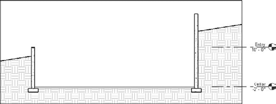
Figure 3.35. This section view illustrates how the building pad adjusts the extents of the topographic surface.
Adjusting the Section Poche for Topographic Surfaces
If you would like to customize the settings for the fill pattern and depth of poche, locate the small arrow at the bottom of the Model Site panel in the Massing & Site tab of the ribbon. Clicking on it will open the Site Settings dialog box as shown here:
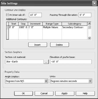
As you can see in this dialog box, you can change the Section Cut Material and the Elevation Of Poche Base settings. Note that the elevation value is in relation to the Revit project base point. You can also adjust the display format of contour lines shown on topographic surfaces as well as the units displayed by property lines.
Property lines are used to delineate the boundary of the lot within which your building will be constructed. These special types of lines are different from simple model lines or detail lines because they can be tagged with standard property line labels that will display segment lengths along with bearings. The property line object can also report its area in a special tag.
You can create a property line in one of two ways: by sketching lines or by entering distances and bearings in a table. In the following exercise, you will create a simple property line by sketching, and then convert the sketched property line into a table of distances and bearings for comparison.
Start a new project using either the
Default.rteorMetricDefault.rtetemplate file and activate the Site plan in the Project Browser.Go to the Massing & Site tab and click the Property Line button. When prompted with the Create Property Line dialog box, choose Create By Sketching.
Switch to the Rectangle tool in the Draw panel of the contextual ribbon and draw a rectangle measuring 120' x 70' (36m x 21m).
Click the Finish Edit Mode button in the contextual ribbon to complete the sketch.
With the property line still selected, click the Edit Table button in the Modify | Property Lines tab of the ribbon. You will be prompted with a warning that you cannot return to Sketch mode once the property line has been converted to a table of distances and bearings. Click Yes to continue.
You will now see each vertex of the property line expressed as a distance and a NE bearing, as shown in Figure 3.36.

In standard construction documentation, it is customary to annotate each vertex of a property line with its distance and bearing. There are two different types of tags you can use to annotate property lines. In the following exercise you will load these two types from Revit's default library and tag each segment of the property line as well as display the area contained within it.
Go to the Insert tab of the ribbon and click the Load Family button. Navigate to Revit's default library; double-click the Annotations folder and then the Civil folder.
Locate the following files and select them both by pressing the Ctrl key (the equivalent Metric library families are shown in parentheses):
Property Line Tag.rfa (M_Property Line Tag.rfa)Property Tag - SF.rfa (M_Property Tag.rfa)
Click Open to load both families.
Go to the Annotate tab of the ribbon and click Tag By Category and uncheck the Leader option in the Options Bar.
Click on each segment of the property line to place the tags indicating the distance and bearing, as shown in Figure 3.37.

Figure 3.37. Tags are applied to display the distance and bearing of each segment of the property line.
Now that you have tagged the individual vertices of the property line, it is time to display the area within the property line. This process is not the same as applying an area tag because an area object doesn't exist for the property line. Instead, the annotation family Property Tag - SF.rfa (M_Property Tag.rfa) is designed to be applied to the property lines when all its segments are selected.
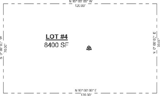
You can try this with the property line you created earlier. Go back to the Annotate tab in the ribbon and click Tag By Category. Instead of picking a single vertex of the property line, hover your mouse pointer over one segment and use Tab-select to highlight the entire chain of property line segments. Click to place the property area tag. Click the question mark above the area to change the name of the property line, as shown in Figure 3.38.
As we mentioned earlier in this section, Revit's site tools are not meant to replace civil engineering software programs. We have shown you how to create a topographical surface in a variety of ways as well as some methods of modifying these objects. There is also a way to quickly quantify how much earth is displaced by proposed changes to existing topography. This is commonly referred to as a cut/fill schedule.
One easy way to demonstrate the use of a cut/fill schedule is through the creation of a building pad which automatically modifies the topographic surface. Let's go through a quick exercise to examine this process.
Open the file
c03-Site-Cut-Fill.rvt, which can be downloaded from this book's website atwww.sybex.com/go/masteringrevit2011.In this file, notice that the topographic surface has been assigned to the Existing phase.
From the View tab in the ribbon, click Schedules and then select Schedules/Quantities to open the Edit Schedule dialog box.
From the Category list, choose Topography and then click OK.
In the Fields tab of the Schedule Properties dialog box, choose Name, Projected Area, and Net Cut/Fill, clicking Add after each one.
Activate the Cellar plan from the Project Browser and create a building pad in the same way you created one earlier in this section.
After you complete the creation of the building pad and the topographic surface is modified, notice that the Net Cut/Fill values in the topography schedule still have a value of 0. This is because the Graded Region tool must be used on a surface to generate the differences required to calculate what volume must be cut versus filled in the proposed design.
Tile the open Revit windows so you can see both the default 3D view and the topography schedule.
From the Massing & Site tab, click the Graded Region tool and then select the topographic surface. When the Edit Graded Region dialog box appears, choose the option Create A New Toposurface Exactly Like The Existing One. This effectively creates overlapping existing and proposed surfaces, which will allow Revit to schedule the differences between the two.
When you select the surface, you will see the volume values in the topography schedule update to reflect how the excavation for the building pad affected the overall soil. Note that this type of calculation does not account for various construction methods such as backfilling.
Try selecting the building pad and changing the Height Offset From Level value. Observe how the Net Cut/Fill values change as the pad helps define the scope of excavation on the site.
You can also make the topography schedule easier to read by assigning descriptive information to each topographic surface. Simply select the surface and enter a value in the Name field in the Properties Palette. Change the name of the main surface to Existing Grade and then locate the surface where the building pad is. Change its name to Pad Area and observe the topography schedule once again.
- Select, modify, and replace elements.
There are many fundamental interactions supported by Revit to select just what you need and to modify elements efficiently.
- Master It
How can you quickly select only the door tags in a plan view and switch them to another type?
- Edit elements interactively.
The editing tools in Revit are similar to those found in other CAD and BIM software programs. Tools such as Move, Copy, and Trim are available on the Modify tab of the ribbon.
- Master It
How do you create a parametric repetition of an element?
- Use other editing tools.
Beyond the basic editing tools are more advanced commands to help you consistently and intelligently populate a building model with content.
- Master It
How do you copy model elements in the same location for a multistory building?
- Creating site context for your Revit project
The site tools in Revit allow you to create context for your building models including topographic surfaces, graded regions and property lines.
- Master It
Describe the different methods used to create a topographic surface.