
Chapter 3: SOLIDWORKS 2D Sketching Basics
The foundation of any 3D SOLIDWORKS model is a 2D sketch. This is because SOLIDWORKS builds 3D features based on the guidance of 2D sketches. This chapter will get you started with SOLIDWORKS 2D sketching. We will cover multiple sketching commands that will allow you to sketch shapes such as rectangles, triangles, circles, and ellipses. You will also learn how to combine those different sketches and create more complex shapes. Then, we will explore the different levels at which SOLIDWORKS defines a sketch. Mastering SOLIDWORKS 2D sketching is essential if we wish to build a 3D model.
The following topics will be covered in this chapter:
- Introducing SOLIDWORKS sketching
- Getting started with SOLIDWORKS sketching
- Sketching lines, rectangles, circles, arcs, and ellipses
- The state of sketches: under defined, fully defined, and over defined
Technical requirements
In this chapter, you will need to have access to SOLIDWORKS.
Check out the following video to see the code in action: https://bit.ly/3GKC1xu
Introducing SOLIDWORKS sketching
In this section, we will discuss what SOLIDWORKS sketches are. We will inform you of the importance of SOLIDWORKS sketching functions and how to view them when modeling with SOLIDWORKS. SOLIDWORKS sketches are the base of each SOLIDWORKS model. Thus, it is important to master SOLIDWORKS sketching first.
The position of SOLIDWORKS sketches
Sketches are typically viewed as fast drafts of a certain shape. For example, the following diagrams show a hand-drawn sketch of a square and a sketch of a cube, respectively. The main point of these is to provide a rough idea of an object.
In this hand-drawn sketch, we are communicating the idea of a square, without specifying how big that object is:
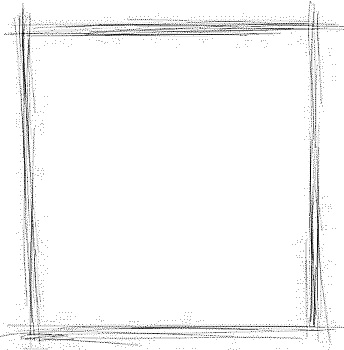
Figure 3.1 – A hand-drawn sketch of a square
Similarly, the following hand-drawn sketch communicates the idea of a cube, without specifying how big the cube is:
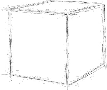
Figure 3.2 – A hand-drawn sketch of a cube
SOLIDWORKS sketches are a bit different. In SOLIDWORKS, a sketch is a fully dimensional and exact shape that's mostly given in two dimensions. SOLIDWORKS also has a 3D sketches function that is more commonly used with surface modeling. In this book, we will only use 2D sketching.
The following diagram shows a SOLIDWORKS sketch of a square with a side dimension of 50 mm. Note that the sketch is different than the one we looked at previously; it is an exact square and not an approximation of a square:
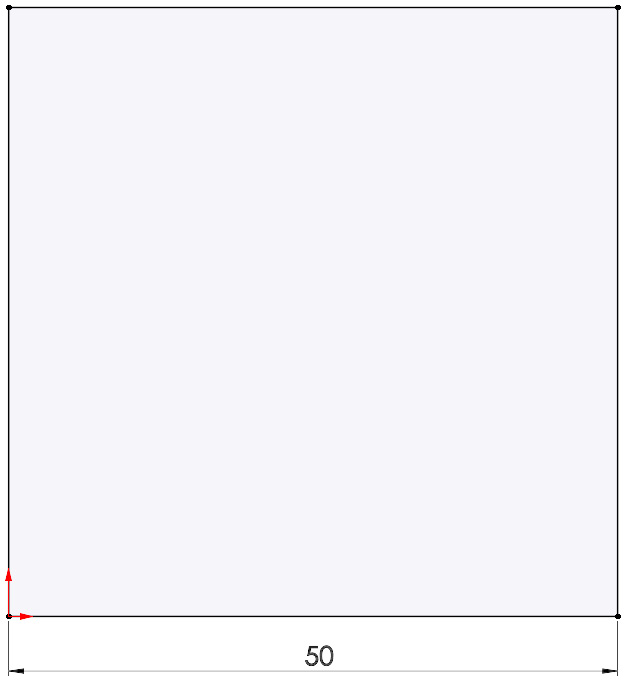
Figure 3.3 – A SOLIDWORKS sketch of a square
SOLIDWORKS sketches are the starting points of any 3D model. They are the basic guiding elements for 3D SOLIDWORKS features. For example, if we want to make a cube, we have to start by drawing the preceding square sketch. After that, we can extrude it to generate a cube, as shown in the following diagram.
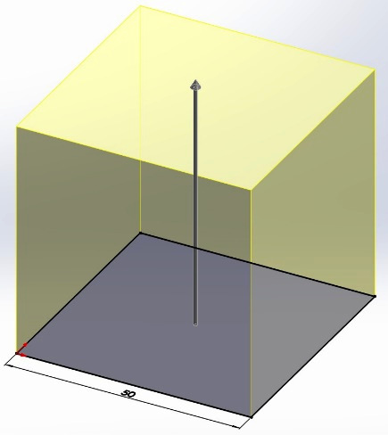
Figure 3.4 – Extruding a cube in SOLIDWORKS
Note that you can see our initial sketch at the bottom of the cube.
When we create a 3D shape in SOLIDWORKS, we often start by creating a 2D sketch and then apply a feature to it. Then, we keep iterating those two steps as the 3D shape becomes more complicated. This is why it is very important that we master SOLIDWORKS sketching before anything else.
The preceding diagram also shows the common sequence of a SOLIDWORKS model, starting with a sketch rather than a feature. The sequence then repeats as the model becomes more complex.
Simple sketches versus complex sketches
SOLIDWORKS has many ready-made commands that we can use to create simple sketch shapes such as lines, squares, circles, ellipses, arcs, and so on. We will learn about these sketching commands in this chapter. However, it is important to understand that all complex sketches are a combination of different simpler sketches.
Let's illustrate this with an example. The following figure shows a sketch of a relatively complex shape:
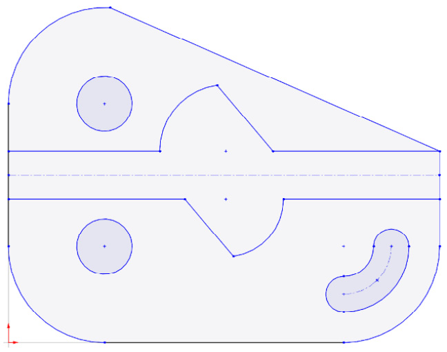
Figure 3.5 – A complex sketch in SOLIDWORKS
Note that the complex shape is made up of a combination of different simple elements. This image can be easily made with four different sketching commands: lines, arcs, circles, and slots. The following figure shows how we can break down the complex sketch into these four sketching commands. All the unmarked elements of the sketch are repetitions of the marked ones. We can refer to each of these elements (a line or an arc, for example) as a sketch entity:
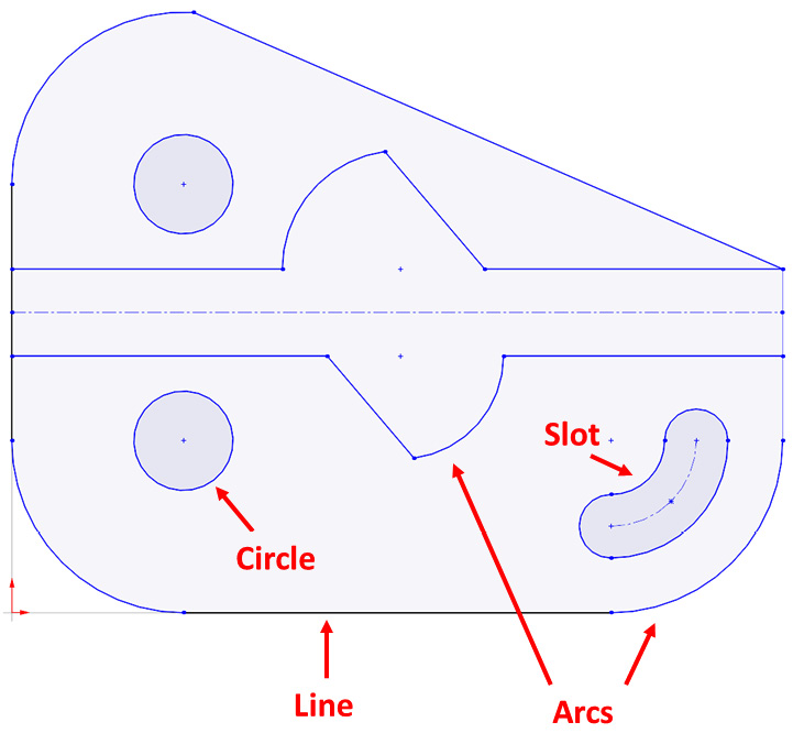
Figure 3.6 – Complex sketches are combinations of simple sketch entities
Simplifying complex sketches so that they're simple elements is a skill that takes time to build. Since we've just started sketching, we may face difficulties simplifying complex sketches. This book will help you develop this skill, but you will become better at it with experience.
Now that we know what sketches are, we can start defining the elements that are involved in our sketches. We will start with sketch planes.
Sketch planes
Sketch planes are flat surfaces that we can use as bases for our sketches. They are important because they give our sketches a solid location. If we didn't have them, our sketches would float undefined in 3D space.
SOLIDWORKS provides us with default sketch planes when we start a new part. We can find them listed in the design tree. The default sketch planes are the Front Plane, the Top Plane, and the Right Plane. They are listed in the following screenshot:

Figure 3.7 – The sketch planes as shown in the software interface
To help you visualize these default planes, imagine a box and the planes being the top, the front, and the right-hand sides of it. The following figure shows the three default planes in the shape of a box:
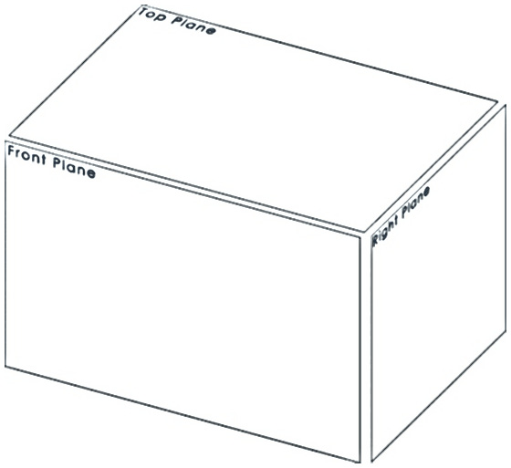
Figure 3.8 – The three base planes reshaped as a box
These three planes are not the only ones that are available to us. In addition to the default planes, we can use any other 2D straight surface as a sketch plane as well. We also have the option of creating our own planes based on different geometrical references. We will explore these possibilities later in the book. Now that we've identified our sketch planes, we can start using those planes to create our sketches.
Getting started with SOLIDWORKS sketching
In this section, we will discuss how to start sketching, what it means to define a sketch, and what the major geometrical relations that exist in SOLIDWORKS sketching are. These topics will be our practical introduction to getting into SOLIDWORKS sketching.
Getting into the sketching mode
To start a sketch, we need to have a part file open. Then, we can follow these steps to get into the sketching mode:
- Select one of the default sketch planes: Front, Top, or Right.
- In the CommandManager, select the Sketch option (which is marked as 2 in Figure 3.9). This will open up the Sketch commands category, which will show all the commands related to sketching.
- Select the Sketch command (which is marked as 3 in Figure 3.9). This will allow us to enter the sketching mode. When we're in the sketching mode, we can apply different sketching commands, such as the marked Simple sketching commands:
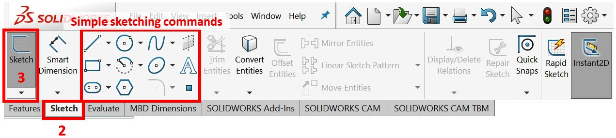
Figure 3.9 – The Sketch tab and the Sketch command
Now that we are in the sketching mode, we can see multiple sketching commands on the command bar. This includes commands for sketching simple shapes such as lines, rectangles, circles, polygons, arcs, and others. Let's go over these commands in more detail. However, since we are already in the sketching mode, take some time to randomly click on those commands and try them out on the canvas.
There are two alternative ways to start the sketching mode, as follows:
- Select the Sketch command first and then select the sketch plane.
- Click on the Sketch shortcut that appears when you click on one of the planes. The following screenshot highlights this shortcut:
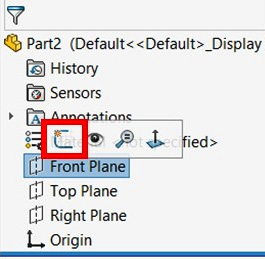
Figure 3.10 – Another way to get into the Sketch mode is to use the popup after selecting a plane
Before we start applying these sketching commands, we will discuss what it means to define a sketch.
Defining sketches
Now that we know how to start sketching, we will learn about what defines a sketch. Constructing a sketch will require two elements: the first is the sketch entities, such as lines, arcs, and circles, while the second is the dimensions and relations that define the sketch entities. Remember that SOLIDWORKS is a form of engineering software that aims to support the design and manufacture of products. Defining sketches ensures the design intent integration in the design. Thus, defining shapes is very important.
To define sketches, we can use dimensions and relations. Let's start by defining them:
- Dimensions: These represent distances and angles that can be defined with a numerical value. Some examples are as follows:
- Lengths of lines
- The diameters and radii of circles and arcs
- An angle between two lines
- Relations: These represent geometric relations between the different parts of a sketch. Some examples are as follows:
- A line that is has a horizontal relation to a sketch plane
- Two lines are perpendicular to each other
- Two circles are concentric to each other
- A line is a tangent to a curve
To illustrate this, let's look at a visual comparison between two lines. One is Fully defined and one is Under defined:

Figure 3.11 – A visual comparison between a fully defined and an under-defined line
Of the two preceding lines, the one on the left is fully defined while the one on the right is under-defined. The line on the left is defined as such because of the following:
- One end coincides with the origin of the coordinate system.
- The length of the line was defined as 50 millimeters.
- The angle between the line and the x axis is 45 degrees.
These dimensions and relations are what make a sketch defined. It may not look like there's much of a difference between them when we look at the two lines, assuming that we drew them on paper. However, when we work with a computer program, we need to let the computer know everything about the line (or any other sketch entity); otherwise, it won't know what we want.
To make it easier to distinguish between fully defined and under defined sketches, SOLIDWORKS color-codes them. Black parts are fully defined, while blue parts are under defined. In addition to color-coding, SOLIDWORKS also indicates the status of our sketch below the canvas. The following screenshot shows an indication of a Fully Defined sketch. Other classifications include Under Defined and Over Defined:
Figure 3.12 – The sketch status classification as found at the bottom of the interface
Note
You can change the default color code through the settings if needed.
Sketches are defined with measurements and relations, where measurements refer to numbers and relations refer to geometrical relations. We will explore geometrical relations in the next section. Also, in the section titled Under defined, fully defined, and over defined sketches, we will be discussing those terms in more depth.
Geometrical relations
The following table summarizes the majority of the geometrical relations we will come across while working with SOLIDWORKS sketching. You don't need to memorize all of these relations for now. Simply read through the following table and use it as a reference as we continue to develop our SOLIDWORKS skills. The relations in the following table have been organized in alphabetical order. In the SOLIDWORKS interface, we will deal with these icons more and more since they will appear in the sketches themselves, as well as when we choose which relation to apply them to:

Figure 3.13 – The geometrical relations for sketching
These icons and their relations will repeatedly show up as we are creating sketches. Thus, it is important that we know what they mean. We will start using these relations in the next section, that is, when we start sketching different shapes.
Sketching lines, rectangles, circles, arcs, and ellipses
In this section, we will discuss the major sketching functions and how to use them. These include sketching lines, rectangles, circles, arcs, and ellipses. We will address each of these sketching commands separately and find out how to define each one.
The origin
On the canvas, you should be able to see a small red dot with arrows, as shown in the following figure. This dot is located exactly where the two red arrows meet and represent the origin point of the canvas. It is also the only defined and fixed point in our SOLIDWORKS infinite canvas:
Figure 3.14 – The SOLIDWORKS graphical representation of the origin
Because it is the only fixed point, it is very important to always link our sketches to that origin point. Otherwise, our sketch will always be under-defined in the infinite canvas.
Sketching lines
To illustrate how to sketch lines, we will sketch the following shape. Note that the sketch is fully defined, and so SOLIDWORKS will show it filled in with black after it's been sketched. Also, take note of the relations and dimensions (in millimeters) shown in the following figure:
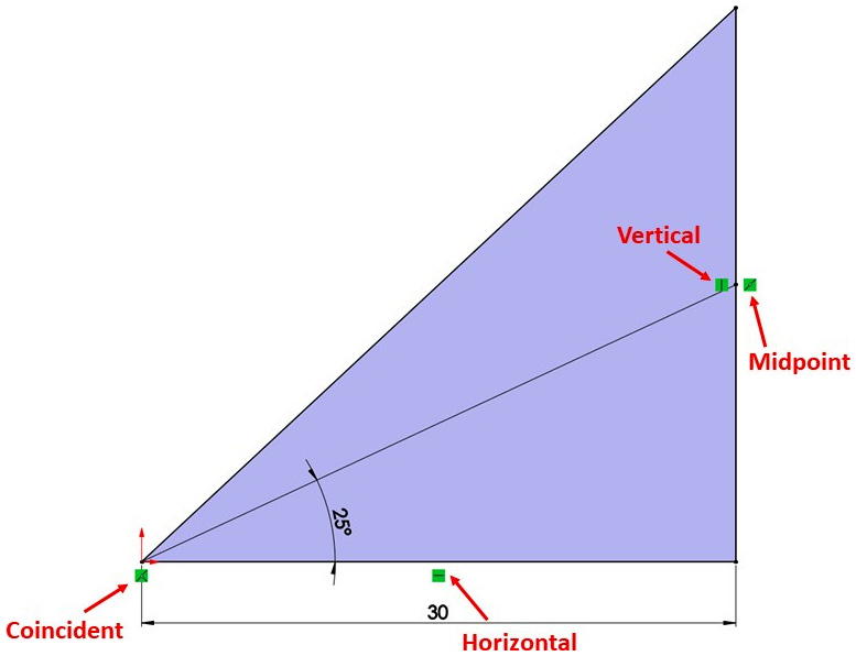
Figure 3.15 – The final output of our sketching exercise
Let's go ahead and start constructing the shown sketch. To do that, we will go through two stages: outlining and defining.
In the outlining stage, our aim will be to draw a rough outline of the final shape. Here, we will not pay much attention to dimensions or relations. We will follow these steps in the outlining stage:
- Start a new part file.
- Set the document's measurement system to MMGS (millimeter, gram, second) if it is not already.
- Navigate to the Sketch mode using the Top Plane.
- Select the Line sketch command as indicated in the following figure.
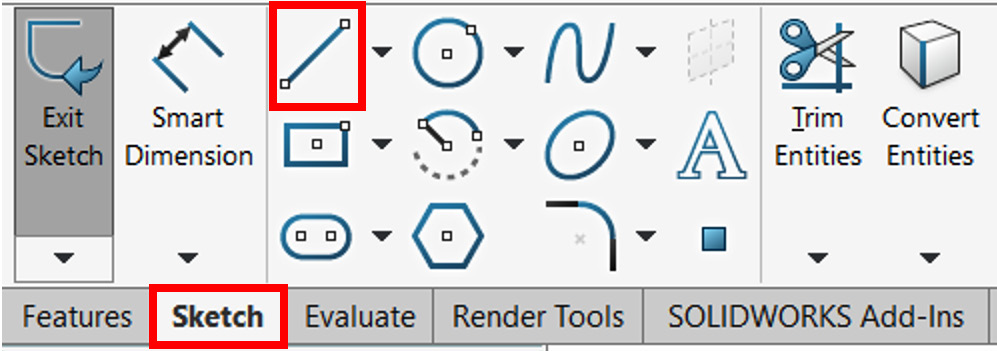
Figure 3.16 – The location of the line command
- Move the mouse cursor onto the canvas and click on the origin. To start drawing the triangle, move your cursor to the right and, once the line is drawn, left-click on your mouse. Note that the shape of the cursor will change into a pen.
- Next, move the mouse more upward to create the second line, and then left-click on the mouse again.
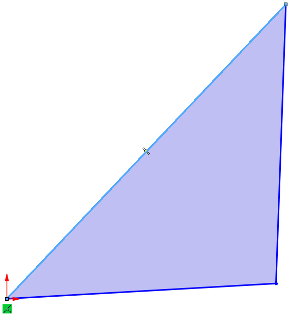
Figure 3.17 – Three under-defined lines forming a triangle
- Move the cursor again to draw a line linking back to the origin. This concludes the creation of a shape that looks like a triangle, as shown in Figure 3.17.
- Now, we can draw the last line, which links the origin point to any point on the vertical line so that we end up with the following sketch. Note that the sketch on the screen is blue, indicating that it is under-defined.
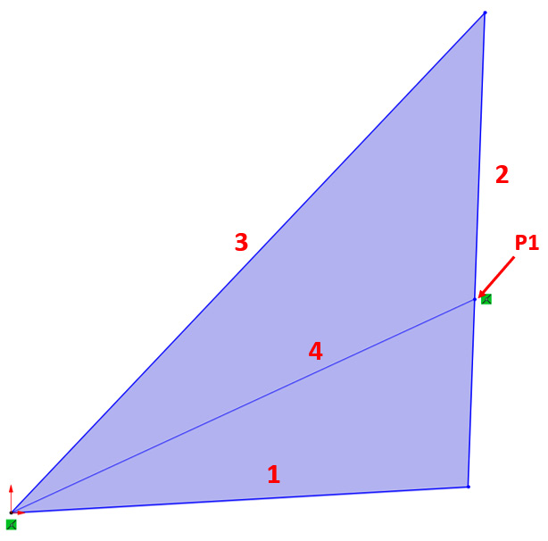
Figure 3.18 – The sketch with all the sketch entitles
In the defining stage, we will work on defining our outline with the necessary dimensions and relations to fully define our sketch. Note that some of the relations are set automatically by SOLIDWORKS, according to how we place our lines. Follow these steps for the defining stage referring to the numbers indicated in Figure 3.18:
- Click on line 1, as indicated by the preceding sketch.
- A new panel will appear on the left, in place of the design tree. It will be titled Line Properties, as shown in the following screenshot. Under Add Relations, click on Horizontal. This will add a horizontal relation to the line. You will see a small icon appear next to the line, showing that the line is horizontal:

Figure 3.19 – The Line Properties manager showing the applicable geometric relations
Note
SOLIDWORKS can apply relations automatically if they can be inferred by how you sketch an entity. For example, if you try to sketch a horizontal line, SOLIDWORKS will apply the relation horizontal to the line automatically. In this case, you will see the relation listed under Existing Relations in the Line Properties.
- Click on line 2 and add a Vertical relation.
Note
- Press and hold down Ctrl on your keyboard, click on the endpoint P1, then click on line 2. From the properties that appear on the left, select the Midpoint relation.
Tip
We can select multiple sketch entries at the same time by clicking and holding down Ctrl on the keyboard and selecting multiple entities.
Note
By following the preceding steps, we will have set up all the relations for our sketch. Note that many parts of the sketch are still blue. Try to click and hold different parts of the sketch, points, or lines and move the mouse around. All the sketch elements will move in a way that preserves all the relations that have been set.
- On the command bar, select the Smart Dimension command, as shown in the following screenshot:

Figure 3.20 – The Smart Dimension command
- Go back to the canvas and click on line 1. A dimension will appear, displaying the current length of the line. Left-click on an empty space in the canvas once more. You will be prompted to enter a length value for the line. Type in the value 30 and then click on the green checkmark, as shown in the following screenshot. After that, you will notice that the line's length changes to match the new length. Also, note that the line, including its endpoints, turns black:

Figure 3.21 – The Smart Dimension interface with space to input the dimension value
- Click on line 1 again, and then click on line 4. Note that the specified dimension changed to the angle between the two lines, which is the dimension we want to specify. Left-click anywhere on the canvas once more to confirm the dimension's location. In the box, type 25, which indicates the degree, and then click the green checkmark.
Note
To delete a dimension, select it and press Delete on the keyboard. Alternatively, we can right-click on the dimension and select Delete from the options that are available.
- Exit the smart dimension mode by pressing Esc on the keyboard or clicking on the Smart Dimension command on the command bar.
Note the shown sketch in the exercise is shaded indicating an enclosure. You can turn this feature on and off by toggling the Shaded Sketch Contours command on the command bar, as shown in the following screenshot.
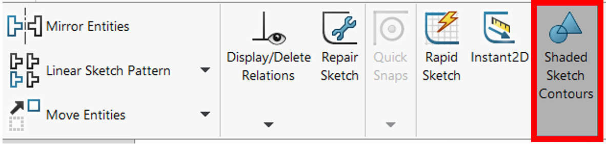
Figure 3.22 – The Shaded Sketch Contours option shades enclosed sketch entities
At this point, we will see that the sketch is fully black, indicating that it is fully defined. This concludes our first sketching exercise. In this simple exercise, we have covered many essential sketching features that we'll keep using when we model with SOLIDWORKS throughout this book, including the following:
- How to start sketching
- How to sketch lines
- How to set up lengths and angles using smart dimensions
- How to set up geometric relations such as vertical, horizontal, and midpoint
These sketching commands are essential to sketching using SOLIDWORKS sketching tools. In the next section, we will use these skills to sketch rectangles and squares.
Sketching rectangles and squares
In this section, we will learn how to sketch rectangles and squares. To illustrate this, we will sketch the following diagram. We have already covered most of the concepts we'll need in order to complete the sketch, including how to get into the sketching mode and how to define a sketch. In this example, the dimensions are in IPS (inch, pound, second), where the length is in inches. Note that we coded the sketch with R1 and R2, indicating rectangles 1 and 2, and S1, indicating square 1:
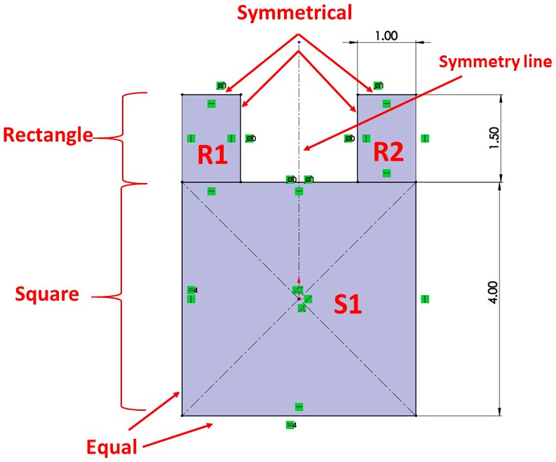
Figure 3.23 – The final output of our sketching exercise
To create this sketch, we will go through the same two stages that we went through previously: outlining and defining.
For outlining, we will draw an arbitrary outline of the final shape we want to draw. Let's get started:
- Start a new part and make sure that the document measurement system is set to IPS (inch, pound, second). Note that we are using a different measurement system for practice purposes here.
- Navigate to the Sketch mode using any of the sketch planes (for example, Front Plane).
- On the command bar, select the drop-down menu next to the rectangle shape and click on the Center Rectangle command. In this exercise, we will use the two rectangle commands, both of which are shown in the following screenshot: Center Rectangle and Corner Rectangle.
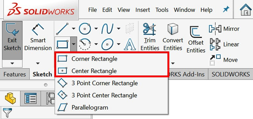
Figure 3.24 – The sketching commands Corner Rectangle and Center Rectangle used in the exercise
Both commands create rectangles; the difference is how those rectangles are created. A Center Rectangle is created with two clicks: one indicating the center and the other indicating a corner. The Corner Rectangle is created with two clicks, indicating the opposing corners. Note that the small figures also show us how to draw that particular type of rectangle by showing us the sequence of clicks that are needed.
- After selecting Center Rectangle, click on the origin, move the mouse to the side, and click away from the origin to form an approximate shape of a square. We are doing this to create square S1.
Tip
You can delete any part of the sketch by highlighting or selecting that part and pressing Delete on the keyboard. Alternatively, you can right-click and select Delete.
- Select the Corner Rectangle command and draw the two rectangles, that is, R1 and R2. For R1, click on the top-left corner of square S1. Then, move the mouse up and away from the first click, then click again to form the rectangle. Do the same for R2:
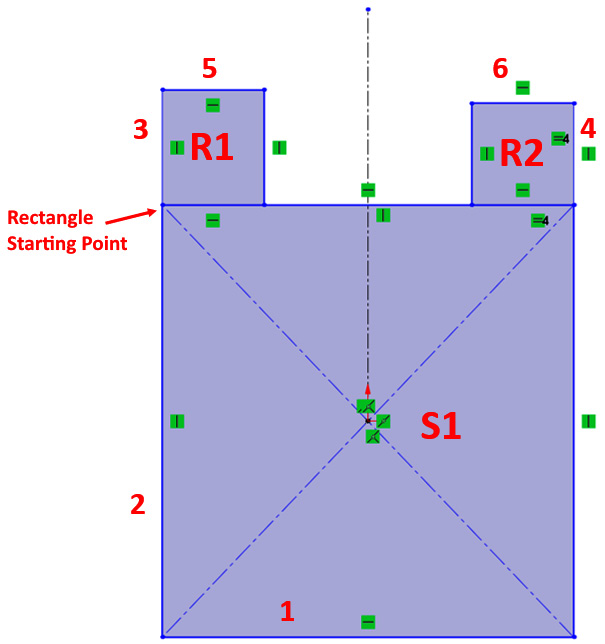
Figure 3.25 – The final result after the outlining stage
- The last step is to add the symmetry line. The symmetry line is a centerline that we will be able to use to create symmetrical relations between parts on opposite sides of that line. To create a centerline, click on the drop-down menu next to the line command and select Centerline. The centerline goes through the middle of the sketch, starting at the origin and going upward.
Tip
Since we are creating the centerline, note that we can move the line endpoint slowly at an angle until the vertical relation appears, at which point, you can lock it on that. This is one way in which SOLIDWORKS interprets the relations we want to apply and applies them for us. We can use this approach to make sketching faster.
For our defining stage, we will define the outlined shape by applying relations and dimensions. Follow these steps to do so:
- Select lines 1 and 2, and apply the Equal relation. This condition is what will make a normal rectangle into a square.
- Select lines 3 and 4, as well as the symmetry line, and apply the Symmetric relation. In this case, SOLIDWORKS will automatically interpret the centerline as the symmetry line since it is located in the middle. You can also do the same with lines 5 and 6.
- Using the smart dimension, set the given lengths so that they match what's shown in the following figure. We can use the smart dimension in the same way we did when we sketched a line:
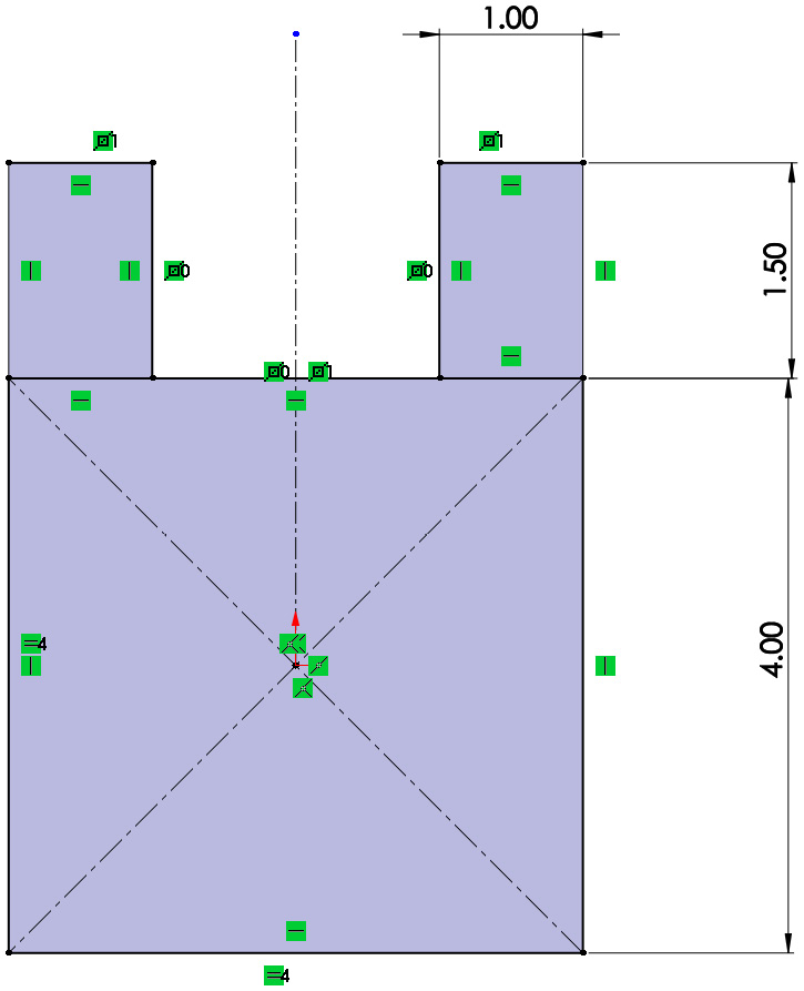
Figure 3.26 – The final sketch being fully defined
At this point, we should have a fully black shape that is fully defined. Also, take note of the status of the sketch, which is shown at the bottom of the SOLIDWORKS screen. It is indicated as Fully Defined, as shown in the following screenshot:
Figure 3.27 – The sketch referenced as fully defined
This concludes our sketching exercise. In this simple exercise, we have covered many essential sketching features that we will capitalize on throughout our SOLIDWORKS interaction, including the following:
- How to sketch squares and rectangles
- How to set up equal-length lines
- How to draw a centerline and set up symmetrical sketch entities
At this point, we already have many of the sketching basics under our belt. Now that we're advancing, we won't need as much guidance as all the commands will start becoming second nature to us. Before moving on, take the time to experiment with creating other types of rectangles, such as the 3 Point Corner Rectangle and the 3 Point Center Rectangle. In addition, take some time to experiment with creating a Parallelogram. We can find all of these shapes in the Rectangle command drop-down menu.
Now, we know how to sketch lines, rectangles, and squares. Next, we will develop our skills by addressing circles and arcs.
Sketching circles and arcs
In this section, we will sketch circles and arcs. First, let's break down what a circle and an arc are. The following figure shows a circle. Note that a circle is defined by its Center (a point) and its Diameter:
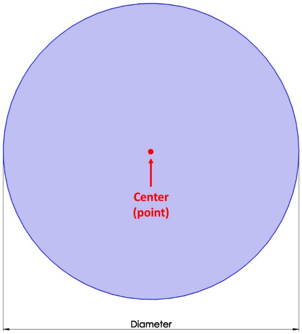
Figure 3.28 – A breakout of a circle
The following figure shows an arc, as well as the elements that define it. An arc can be defined by its Center (a point), as well as other points, which indicate the endpoints of the arc. This is in addition to its Radius and various distances:
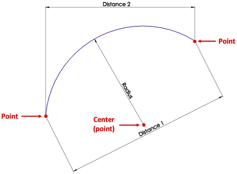
Figure 3.29 – A breakout of an arc
Each of these elements can be controlled with dimensions or relations. Each point can be understood as a standalone entity that we can use for relations or dimensions.
To illustrate these two commands, we will sketch the following shape:
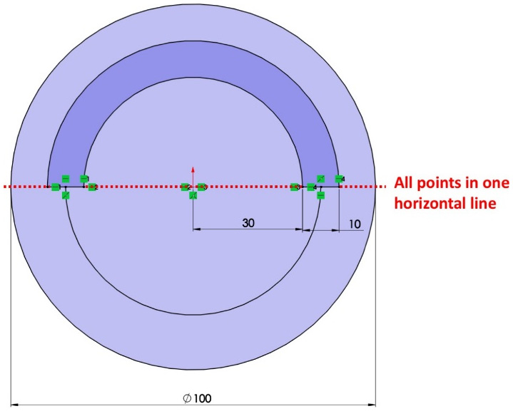
Figure 3.30 – The final result of this sketching exercise
Similar to what we did previously, we will do outlining and then defining. We will start with the outlining stage, as follows:
- Open a new part file and make sure that the measurement system is set to MMGS (millimeter, gram, second). Note that we have selected MMGS for practice purposes only.
- Navigate to the Sketch mode using any of the default planes (for example, Top Plane).
- On the command bar, select the Circle command. Click on the origin, and then move the mouse further to form a circle. Click again to finish drawing the circle:
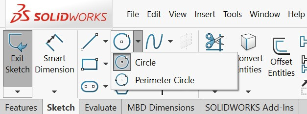
Figure 3.31 – The Circle sketching command
- Click on the Centerpoint Arc command and follow the instructions shown in the small command image:
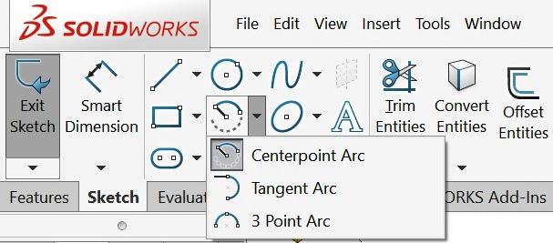
Figure 3.32 – The CenterPoint Arc sketching command
- Connect the endpoints of the arcs using the Line sketch command. The result will be similar to the following figure. Note that we indicated the different points of the sketch using the letters P1-P4, which stand for point 1, point 2, and so on:
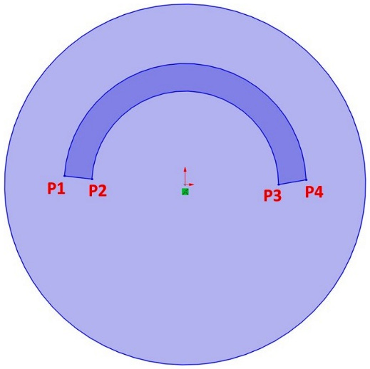
Figure 3.33 – The arcs endpoints can be connected using lines
- Use the Centerpoint Arc to create the last lower arc, which links the two lines we created in Step 5, to create the following sketch:
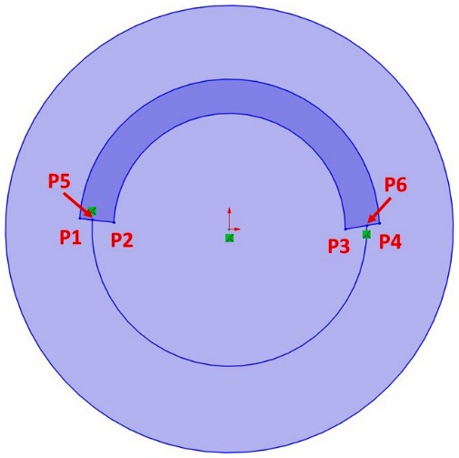
Figure 3.34 – All the sketch entitles required for our shape
Now that we've finished outlining, we can start defining the sketch elements in the defining stage. Let's get started:
- Note that P1, P2, P3, P4, and the origin are all in a horizontal line in the initial image for this exercise. To do this, select all the points and the origin and select the Horizontal relation. Alternatively, we can do the same in more steps by selecting P1 and the origin and setting the relation to Horizontal. We can then do the same with P2 and the origin, P3 and the origin, and P4 and the origin.
- Set a Midpoint relation between P5 and lines P1 and P2. Do this by selecting the point, P5, and the line it is on, and then select the Midpoint relation. Do the same for P6 and lines P3 and P4.
- Set the dimensions shown in the following figure using the Smart Dimension function:
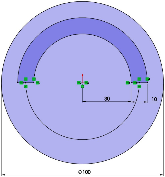
Figure 3.35 – The final sketch fully defined
This concludes this exercise of using circles and arcs. At this point, our sketch is fully defined. Before moving on, take some time to individually experiment with creating a Perimeter Circle, a Tangent Arc, and a 3 Point Arc. These are some other ways we can create circles and arcs that we did not explore in this exercise. However, all these commands follow the same principles when it comes to making circles and arcs. Now that we've mastered how to create circles and arcs, we will address ellipses and construction lines.
Sketching ellipses and using construction lines
In this section, we will discuss what ellipses are, how to define them, and how to make them in SOLIDWORKS. We will also touch on the idea of construction lines. We can look at an ellipse as a combination of two axes and five points, as shown in the following figure:

Figure 3.36 – A breakout of what makes an ellipse
When we define an ellipse in SOLIDWORKS, we can use the four points and the center as our defining factors. We can also define an ellipse with the help of construction lines, which we can use to define the size and the location of the ellipse. To illustrate this, we will sketch the following ellipse:

Figure 3.37 – The final result of this sketching exercise
Similar to all our other exercises, we will sketch the ellipse in two stages: outlining and then defining. Let's start with our outlining stage:
- Start a new part file and set the measurement system to MMGS (millimeter, gram, second).
- Start the Sketch mode using the Right Plane (or any other plane).
- Select the Ellipse command from the command bar:

Figure 3.38 – The Ellipse sketching command
- We will need to click three times to create an ellipse. First, click on the origin. Then, move the mouse to create the major axis and then left-click to confirm this. After that, move the mouse once more to create the minor axis and left-click again to confirm this. Make sure that the ellipse is tilted a bit to avoid unnecessary automated relations being made by SOLIDWORKS. We should have a shape similar to the one shown in the following figure:

Figure 3.39 – An arbitrary starting sketch for an ellipse
As usual, now that we've finished our shape outline, we can start our definition stage:
- First, use a smart dimension to define the lengths of the major and minor axes. We will set them to 60 mm for the minor axis and 120 mm for the major axis. We can define the lengths of the axes by defining the distance between the points on the perimeter of the ellipse.
- To set up the angle of the ellipse, we can use construction lines. Construction lines are dotted lines that are used for the purpose of supporting the definition of our sketches. However, they are not accounted for by SOLIDWORKS when building features. To set up construction lines, select the normal Line command and then check the For construction option in the Options panel on the left, as shown in the following screenshot. After that, all the lines we sketch will be construction lines:
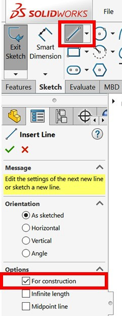
Figure 3.40 – The construction line setup from the line property manager
Alternatively, we can sketch normal lines and turn them into construction lines. Do that by clicking on the normal line or any other sketch entity and checking For construction from the Options tab that appears on the left.
- Draw the two construction lines that are shown in the following figure:

Figure 3.41 – Construction lines can play a role in defining our sketches
- Using the smart dimension, set the angle between the two construction lines to 40 degrees.
This concludes this exercise on creating an ellipse. In this exercise, we covered how to draw and define an ellipse, and what construction lines are and how to utilize them to define our sketches.
In the exercise, we defined construction lines using the Line Properties. However, you can also sketch one directly using the drop-down menu for the Line command and selecting Centerline as shown in the following figure.

Figure 3.42 – The Centerline command can directly sketch construction lines
Both ellipses and construction lines will be very useful as we advance our SOLIDWORKS skills. Now, we will look at the fillets and chamfers commands so that we can improve our sketching skillset further.
Fillets and chamfers
In this section, we will discuss making fillets and chamfers for our sketches. Fillets and chamfers can be applied between two sketch entities, usually between two lines. They are defined as follows:
- Fillets: Fillets can be viewed as a type of arc. Thus, they are defined in the same way, that is, with a center and a radius.
- Chamfers: Chamfers can be defined in different ways. These include two equal distances, two different distances, or a distance and an angle.
The following figure illustrates the shapes of fillets and chamfers, as well as how they are defined:
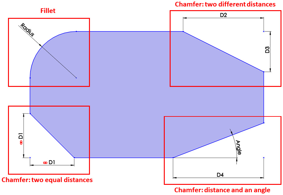
Figure 3.43 – The sketch fillets and the different types of chamfers
To illustrate how to create fillets and chamfers, we will sketch what's shown in the following figure:
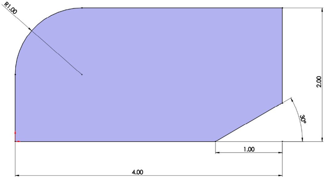
Figure 3.44 – The final result of this sketching exercise
Fillets and chamfers are different than other sketching commands in that we will apply and define them at the same time. Thus, they won't follow our typical procedure of outlining and then defining. To create the sketch, we will use the IPS measurement system. To achieve the preceding sketch, we will need to sketch a 4 x 2-inch rectangle, which will be our starting point. Note that we marked the different lines with the letter L and marked the different vertices with the letter V for ease of reference:
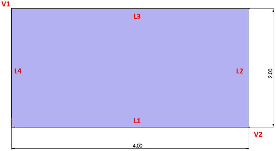
Figure 3.45 – A fully defined rectangle as a starting point to apply the fillet and chamfer to
Now, we can start creating the fillet, as follows:
- A sketch is positioned based on a vertex or the two lines around a vertex. Select lines 3 and 4 (L3 and L4) and then select the Sketch Fillet command from the command bar, as follows. Alternatively, we can select vertex 1 (V1) and then select the Sketch Fillet command:

Figure 3.46 – The Sketch Fillet command
- This will bring up a preview of the fillet on the canvas. You can find more options on the left-hand side, in place of the design tree, as shown in the following screenshot. Under Fillet Parameters, fill in the radius of the fillet as 1 inch. Then, click on the green checkmark. This concludes making the fillet. Now that we've made the fillet, we can press Esc on the keyboard to exit the fillet sketching mode:

Figure 3.47 – The Sketch Fillet property manager showing the fillet parameters
Tip
Press Ctrl + Z to undo the fillet you've applied.
Now that we've sketched the fillet, we will move on to sketching the chamfer:
- The chamfer that we had in our final sketch is defined by an angle and a distance. Note that the angle displayed indicates the angle measurement between L2 and the chamfer itself. Thus, hold down Ctrl, select L1, and then select L2. After that, select the Sketch Chamfer command. Similar to the Fillet command, we will get a preview of the chamfer. Also, on the left-hand side, we will find more options that we can use to define our chamfer.
- Select Angle-distance. Then, set the angle to 30 degrees and the distance to 1 inch.
- Click on the green checkmark afterward:

Figure 3.48 – The Sketch Chamfer property manager showing the chamfer parameters
Tip
If you apply the wrong chamfer, you can click on the Undo button. Alternatively, you can press Ctrl + Z on your keyboard.
This concludes how to create fillets and chamfers. In this exercise, we learned what fillets and chamfers are and what defines them, and how to create fillets and chamfers in SOLIDWORKS sketching mode.
Now we know how to use all the major basic sketching commands. You will use these commands over and over again when working with the software. Now, we will dig deeper into what the different types of definition statuses mean, that is, under defined, fully defined, and over defined.
Under defined, fully defined, and over defined sketches
SOLIDWORKS sketches can fall under three status categories according to how they are defined. They can be under defined, fully defined, or over defined. These terms have already been mentioned briefly, but in this section, we will explore what those statuses are, as well as some ways to deal with them. We will explore these different statuses by drawing and defining a triangle that's under defined so that it becomes over defined.
Under defined sketches
Usually, the starting point of a sketch is under defined. Under defined sketches have parts of them that are loose or lack proper definition; for example, a line without a specific length. To find out more about under defined sketches, we'll examine the following sketch. We will use the MMGS measurement system for this exercise. We have indicated the lines and points with the letters L and P for reference:

Figure 3.49 – An under defined sketch consisting of three unrestrained lines
Take some time to sketch the preceding sketch and examine it. From this sketch, we can see the following:
- Note that, in your SOLIDWORKS canvas, P1 and L1 are black in color. Black colors indicate that those parts are fully defined. To test this further, click and hold P1 or L1 and try to move the mouse. You will notice that the sketch doesn't move. This is an indication that that part of the sketch is fully defined.
- The other parts of the sketch (P2, P3, L2, and L3) are blue in color. This indicates that those parts haven't been defined yet. To test this, click and hold any of those parts and move the mouse. You will notice that those sketch parts move around the canvas. If any part of the sketch is blue, the sketch will be labeled as Under Defined at the bottom of the SOLIDWORKS interface, as shown in the following screenshot:
Figure 3.50 – The sketch indicated as under defined
We will always try to make our sketches fully defined. To fully define a sketch, we can simply add more dimensions and/or relations to turn the blue parts black.
To find out which parts of the sketch need definition, we can click and hold on any of the blue parts and move them. The resulting movement tells us which parts need definition. For example, if we hold and move P2 left and right, we will notice that L1 changes in length. This indicates that we can define P2 by setting a dimension for L1 (or between P1 and P2), as shown in the following figure. After defining the length, we will notice more lines turned black. Now, if we click on P2 and try to move it, it will be fixed:
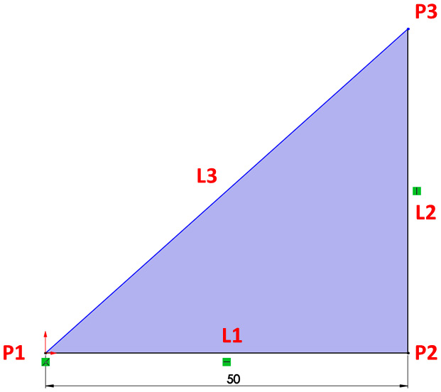
Figure 3.51 – A sketch that is partially defined, with the interface showing blue and black lines
We can do the same movement test for L3 and P3 and decide what elements of the sketch we can define further.
Fully defined sketches
Fully defined sketches are where all of the parts of the sketch are fully fixed. In other words, no part of the sketch can be moved from its current position. To illustrate this, we will take another look at the sketch we started and fully define it. We will do this by adding an angle of 45 between L1 and L3. The fully defined result is as follows:
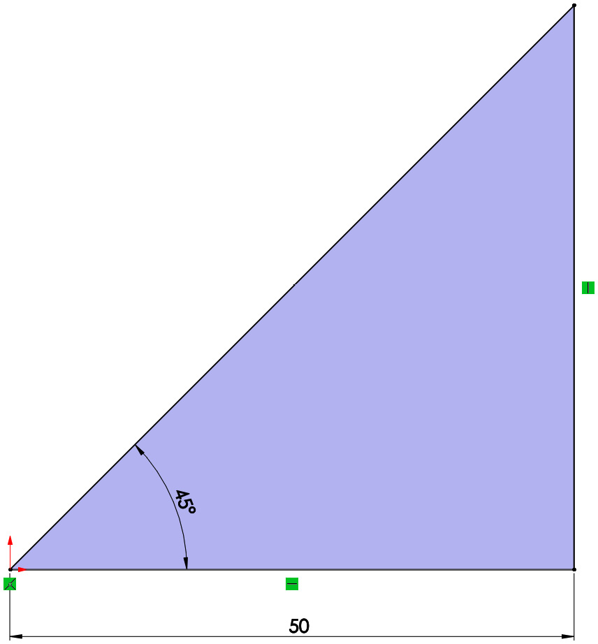
Figure 3.52 – A fully defined triangle
Note that the sketch is now fully black on your screen. Also, if you hold and try to move any of the sketch parts, they will not move because they are fully restrained. When the sketch is Fully Defined, SOLIDWORKS will take note of this at the bottom of the interface. Remember that we fully defined a sketch by adding relations and dimensions until all the sketch elements were fixed:
Figure 3.53 – The sketch indicated as Fully Defined
When sketching with SOLIDWORKS, we will mostly try to make our sketches fully defined in order to capture our full design intent. Now, let's look at over defined sketches.
Over defined sketches
Over defined sketches are those with more relations and dimensions than are needed for the sketch elements to be fully fixed. This is not a recommended status to have for a sketch. Over defined sketches occur when we apply contradicting relations to define a particular part of a sketch. To illustrate this, we can add an extra dimension to L2. Once we do that, we will get the following message:
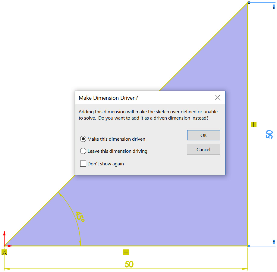
Figure 3.54 – A warning for over defined sketches
Let's examine these two options and their results:
- Make this dimension driven: This will make the dimension so that it's just for show. This option will only tell us the length of the line. If the lengths of the other lines change, the displayed length here will change accordingly. Choosing this option will not cause any issues.
- Leave this dimension driving: This will give the dimension driving power, just like the other dimensions. However, since the sketch is fully defined already, selecting this option will leave our sketch with conflicting items and a warning message that the sketch is Over Defined, as shown in the following screenshot. Once we are in an over defined sketch situation, we will need to delete some existing relations or dimensions to get rid of the over defined status. In SOLIDWORKS, we shouldn't set more than one relation or dimension that governs the same sketch entity, even if they are geometrically non-conflicting:
Figure 3.55 – A sketch indicated as Over Defined
Keep in mind that the best practice is to have our sketches fully defined to ensure that we are fully capturing the design intent of our sketch.
All the definition statuses are related to how many relations and dimensions we add to our sketch. A fully defined sketch has all the sketch elements fully fixed with the proper number of relations and dimensions to fully capture the design's intent. Under defined sketches have fewer relations than they require, and over defined sketches have more relations than needed.
Summary
In this chapter, we learned about the different aspects of SOLIDWORKS sketching that form our sketching foundations. We learned what sketching is and how to sketch different sketching elements, including lines, rectangles, circles, arcs, ellipses, fillets, and chamfers. We also covered using dimensions and relations to define sketches, as well as the meaning of the different sketch definition statuses, that is, under defined, fully defined, and over defined.
All of this information is part of our sketching foundation, which we will use every time we build a 3D model with SOLIDWORKS. In the next chapter, we will address additional sketching commands that can greatly enhance our sketching performance and speed, such as patterns and mirrors.
Questions
Answer the following questions to test your knowledge of this chapter:
- What is the position of SOLIDWORKS sketching in modeling?
- What are the two stages we commonly follow when sketching?
- Sketch the following shape using the MMGS measurement system:
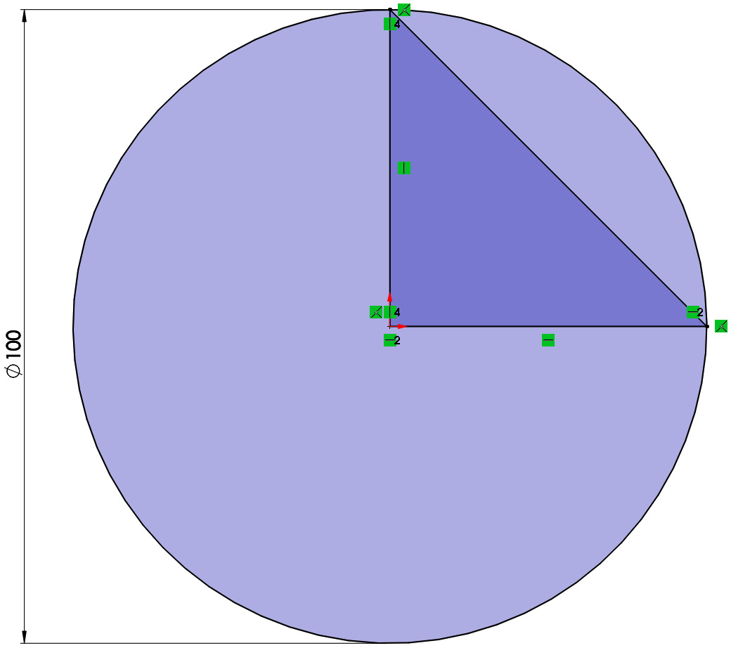
Figure 3.56 – The final output of question 3
- Sketch the following shape using the IPS measurement system:

Figure 3.57 – The final output of question 4
- Sketch the following shape using the CGS measurement system:

Figure 3.58 – The final output for question 5
- Sketch the following shape using the MMGS measurement system:
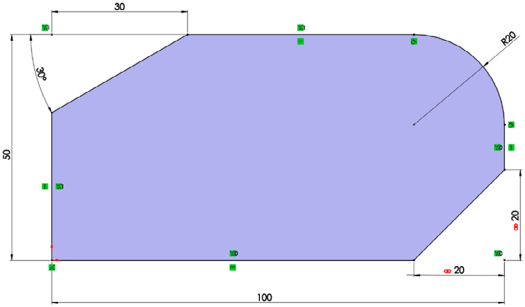
Figure 3.59 – The final output for question 6
- What are under defined, fully defined, and over defined sketches?
Important Note
The answers to the preceding questions can be found at the end of this book.