
Project 1: 3D-Modeling a Pair of Glasses
SOLIDWORKS is a 3D-design tool. As with all tools, the more you use it, the better you become at it. In this project chapter, you will be provided with work that you can complete to hone your skills. In this project, you will be 3D-modeling and assembling a pair of glasses from a set of engineering drawings.
This project chapter will cover the following topics:
- Understanding the project
- 3D-modeling the individual parts
- Creating the assembly
By the end of this chapter, you will have more confidence in using the different SOLIDWORKS tools for practical projects.
Technical requirements
You will need to have access to SOLIDWORKS to complete the project.
Understanding the project
Understanding what the project entails is essential before starting the work. This will allow you to draw a plan and manage your work expectations when completing the project. For this exercise project, you will be 3D-modeling a pair of glasses, as shown in the following figure:
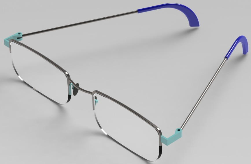
Figure P1.1 – The pair of glasses you will 3D-model in this project
The pair consists of 15 parts, 8 of which are unique. The following figure highlights the bill of materials, showing the names of the parts, their quantity, and position in the assembly:

Figure P1.2 – The pair and the bill of material
At this point, you already have an idea of the project's outcome and the complexity of the required parts and assembly. In this next section, we will provide you with the engineering drawings needed to replicate all the parts and assembly. Now that we have an idea of the project's final output, we can discuss how you can tackle it in the context of this writing.
Important Note
The drawings and 3D models presented in this project are for practice purposes rather than manufacturing purposes.
There are two ways in which you can tackle this project, depending on your 3D-modeling level. They are as follows:
- Moderate level: Take a look at the provided drawings and hints to complete the project.
- Advanced level: Only take a look at the drawings without using the hints.
Other than the two suggested approaches, you can also design your own way to 3D-model the glasses utilizing the provided drawings and selected hints.
Tip
You can treat the project as your own and customize the provided glasses to end up with your own unique design.
In this write-up, we will first explore the individual parts and then move on to the assembly. So, let's get started with the parts. We will also provide you with hints that can assist you with your work.
3D-modeling the individual parts
In this section, we will explore the different part drawings to make up the pair of glasses. The provided drawings have enough information for you to replicate all the parts to end up with an identical result to the one shown in Figure P1.1.
Thus, one option you have for going about the project is to create an exact replica of the given drawings. However, you can also choose to customize and adjust different elements of the design to make it your own. Keep in mind that this is your project, so feel free to treat it as such.
Creating the individual parts
The provided pair of glasses consists of 15 parts. However, 8 parts are unique, which you will need to 3D-model, as highlighted in Figure P1.2. The parts you will need to 3D-model are as follows:
- Lens frame
- Lens
- Bridge
- Nose link
- Nose pad
- Connector
- Temple
- Temple tip
Important Note
The names of the parts presented in the bill of materials might be different to the names practiced in different parts of the world.
Your task is to use the presented drawings to 3D-model the individual parts. As you are 3D-modeling the different parts of the glasses, keep in mind that there is no one correct way of 3D-modeling any of the parts. However, we will provide you with some hints that can push you forward if you find yourself getting stuck. You can also feel free to customize your own design using the given drawings as a base of inspiration.
Important Note
The order in which the following drawings are listed is arbitrary.
Let's start exploring the drawings one after the other. The first drawing is for the lens frame:

Figure P1.3 – A detailed drawing for the lens frame
Here is a sample procedure for 3D-modeling the lens frame:
- You can start with an extruded boss to create the main shape of the frame, as shown in the following figure:

Figure P1.4 – An extruded cut can be used to start the lens frame
- Apply fillets to get the rounded edges.
Next, we can look at the lens itself, which will be held by the lens frame:
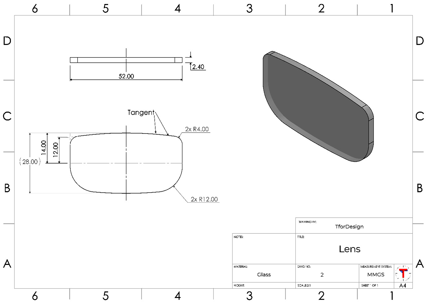
Figure P1.5 – A detailed drawing for the lens
Here is a sample procedure for 3D-modeling the lens:
- Use an extruded boss to build the following shape:

Figure P1.6 – A possible first step in creating the lens using an extruded boss
- Use fillets to round the corners.
After the lens, we can explore the bridge, which will be at the center of the glasses.
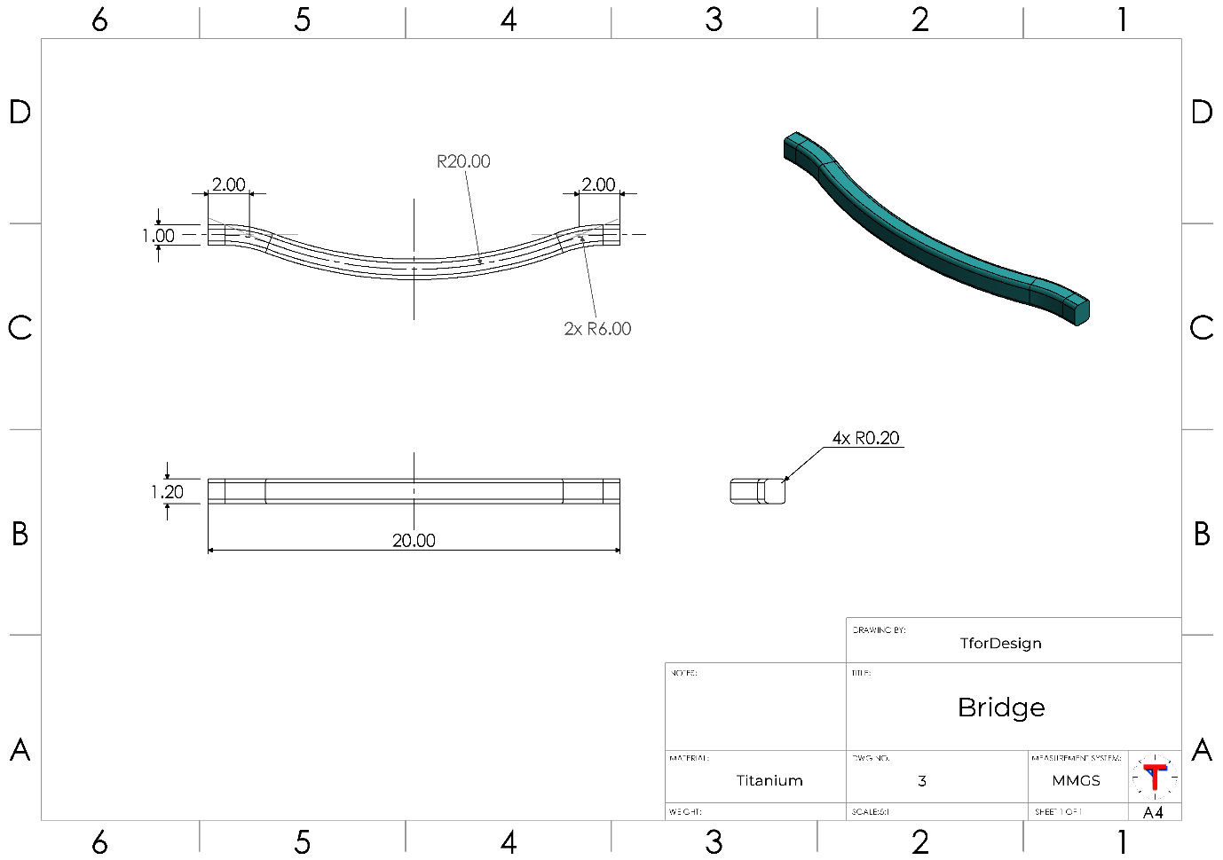
Figure P1.7 – A detailed drawing for the bridge
Here is a sample procedure for 3D-modeling the Bridge:
- Use a swept boss with a square profile to create the basic structure, as shown in the following figure:
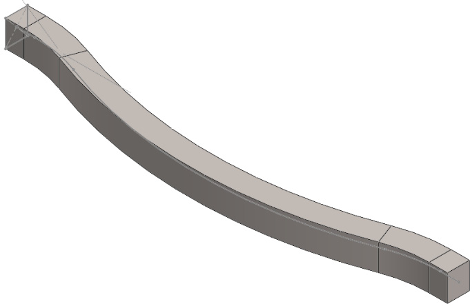
Figure P1.8 – A swept boss can be used to create the bridge
- Use the fillet feature to round out the rounded corners, as shown in Figure P1.7.
After the bridge, we can take a look at the nose pad, which will be connected to the nose link and resting on the nose of the user.

Figure P1.9 – A detailed drawing for the nose pad
Here is a sample procedure for 3D-modeling the nose pad:
- Use an extruded boss with an elliptical sketch to create the following shape:
Figure P1.10 – An extruded boss can create the bulk of the nose pad
- Apply another extruded boss to create the cylindrical extrusion, as shown in the following figure:

Figure P1.11 – A second extruded boss can be used to create the small step on the nose pad
- Use the fillet feature to create the rounded R0.4 mm edges.
Next, we can have a closer look into the connector, which will be linked to the lens frame on one side and the temple rod on the other side.
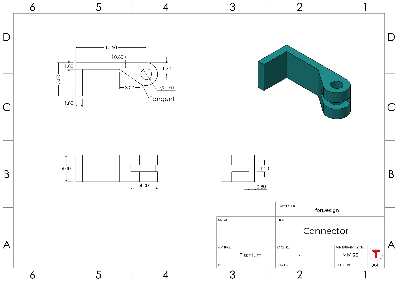
Figure P1.12 – A detailed drawing for the connector
Here is a sample procedure for 3D-modeling the connector:
- Use an extruded cut to create the main shape of the connector, as shown in the following figure:
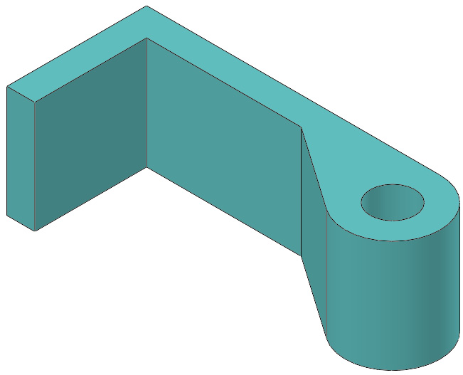
Figure P1.13 – Most of the connector can be done with one extruded boss
- Use an extruded cut to create the middle cut to end up with the following shape:
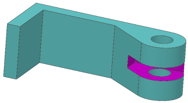
Figure P1.14 – The slot in the connector can be created with an extruded cut
After the connector, we start working on the temple, which is the long part that links to the connector and helps hold the glasses against the user's ears.
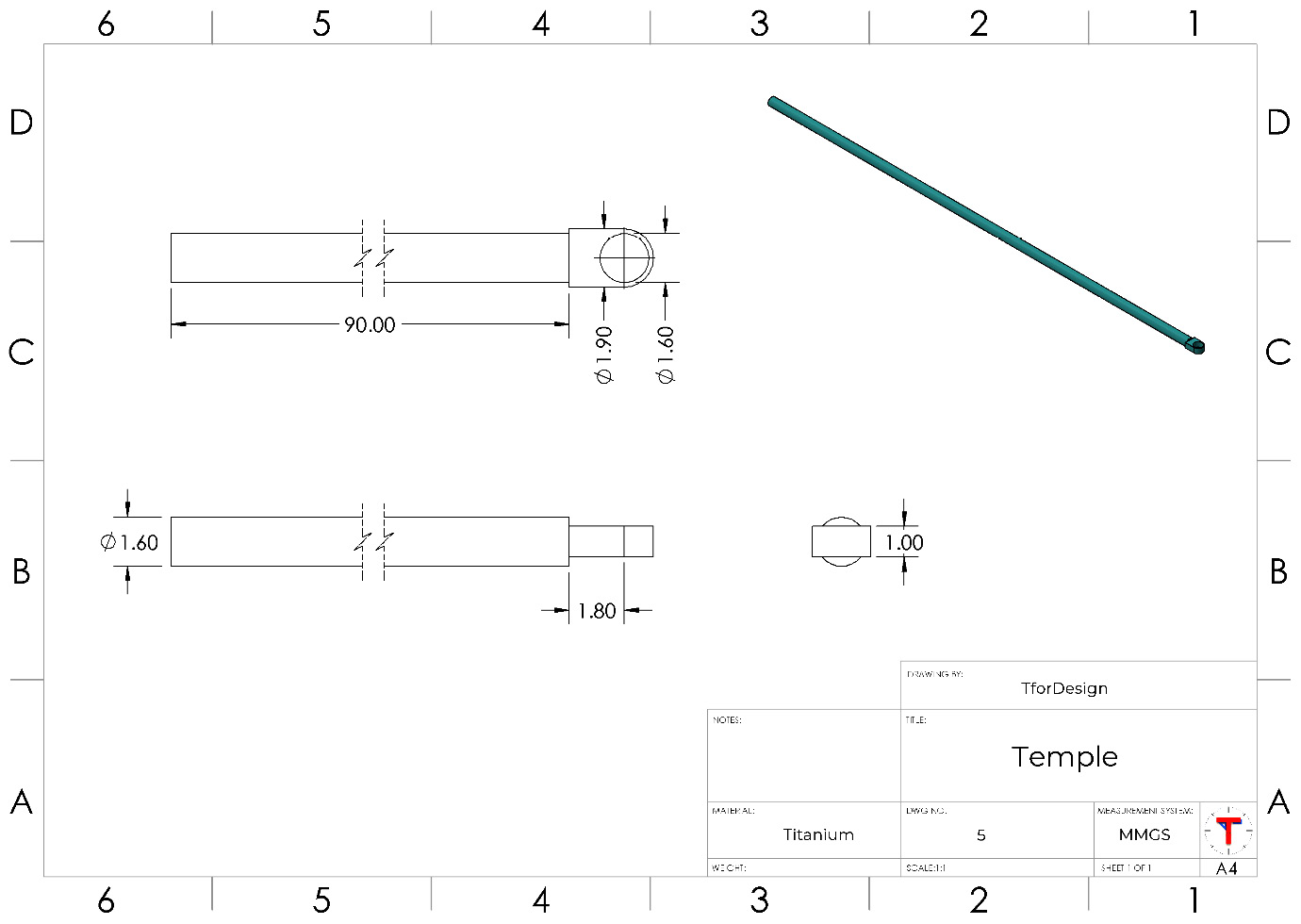
Figure P1.15 – A detailed drawing for the temple
Here is a sample procedure for 3D-modeling the temple:
- Use the Extruded Boss feature to create the following shape:
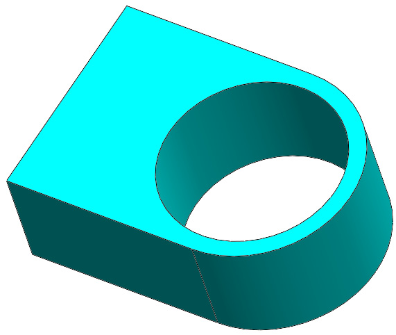
Figure P1.16 – An extruded boss can generate the ring-end of the temple
- Apply another extruded boss to create the long cylindrical rod ending with the final temple, as shown here:
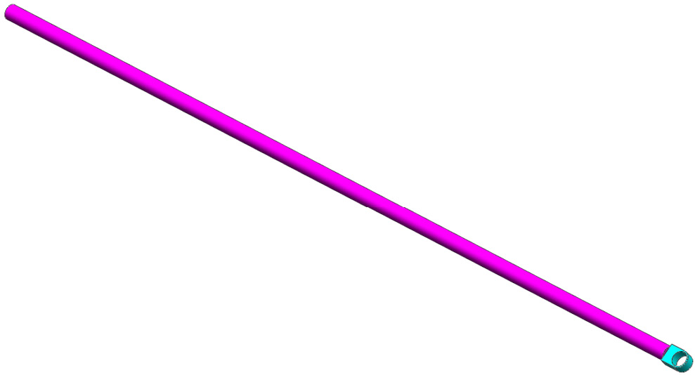
Figure P1.17 – The 90 mm-long cylindrical part can be created with an extruded boss
Note that the drawing in Figure P1.15 utilizes break lines to shorten the length of the temple rod in the drawing sheet.
Next, we can start looking at the last part, the temple tip, which is the relatively softer part touching the user's ear.
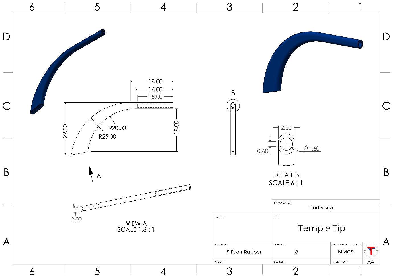
Figure P1.18 – A detailed drawing for the temple tip
Here is a sample procedure for 3D-modeling the temple tip:
- We can use the Lofted Boss feature with guide curves to create the shape of the temple tip. We can use sketches that resemble the following:
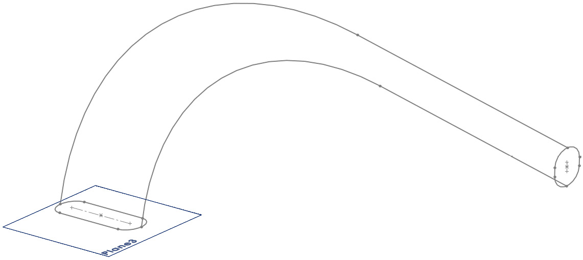
Figure P1.19 – The profiles and guide curves used to create the base lofted boss
- Using the sketched profiles and guide curves, use the Lofted Boss feature to end up with the following shape:
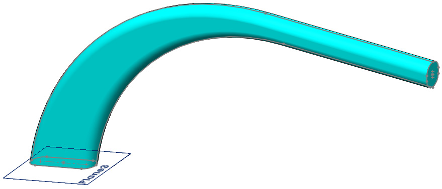
Figure P1.20 – The resulting shape after applying the lofted boss
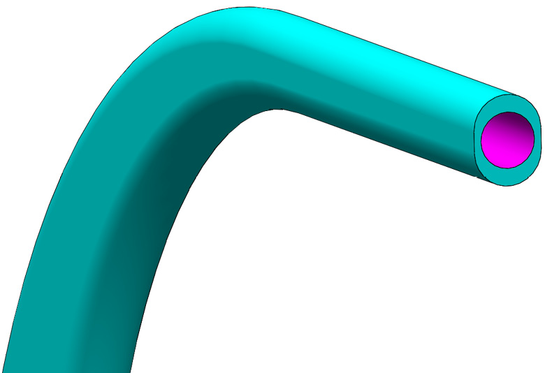
Figure P1.21 – The hole in the temple tip can be made with an extruded cut
Next, we can have a closer look at the nose link, which will link the frame of the glasses to the nose pad.
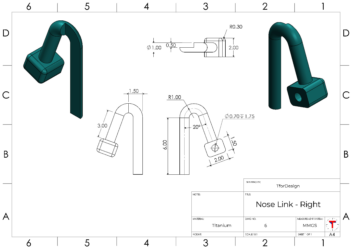
Figure P1.22 – A detailed drawing for the nose link
Here is a sample procedure for 3D-modeling the nose link:
- Use a swept boss with a circular profile to create the tube-looking shape of the nose link, as shown in the following figure:

Figure P1.23 – A swept boss can be used to start creating the nose link
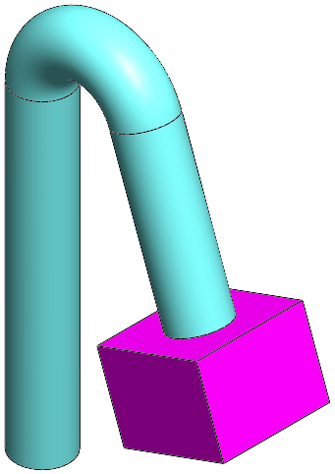
Figure P1.24 – An extruded boss built using a face resulting from the swept boss
- Use the Extruded Cut feature to generate the 0.7 mm diameter circular hole on the block, as shown in the following figure:
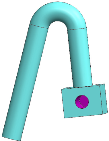
Figure P1.25 – The circular hole in the nose link can be created with an extruded cut
- Use an extruded cut to cut off a rectangular part of the nose link, as indicated in the following figure:
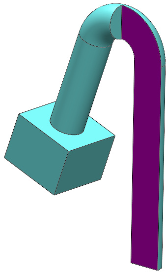
Figure P1.26 – A rectangular sketch can be used with an extruded boss to create the cut
- Use the Fillet feature to create the R0.3 mm rounded edges.
By this stage, we are done 3D-modeling all the unique parts for our glasses. Feel free to treat the glasses as your own by adjusting the sizes and changing the design. There are no right or wrong answers to how to 3D-model. Next, we will create the mirrored part for our nose link.
Creating a mirrored part
A mirrored part has the same features as the original part, but is flipped around a specific plane. They are similar to our right and left arms. Both arms have the same features. However, they are mirrored off one another. Another common example around us is the right and left earphones, right and left shoes, right and left casings, and so on.
The nose link part has right and left configurations in the pair of glasses we are creating for this project. We have already created the right nose link. We can create the left part by following these steps:
- Open up the nose link part we created earlier.
- Select the mirroring plane, as shown in the following screenshot:
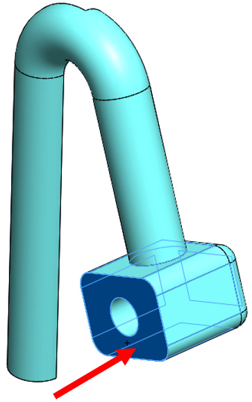
Figure P1.27 – The face to use as a mirror plane to mirror the part
Tip
Any plane, including new reference planes, can be used to create the mirrored part.
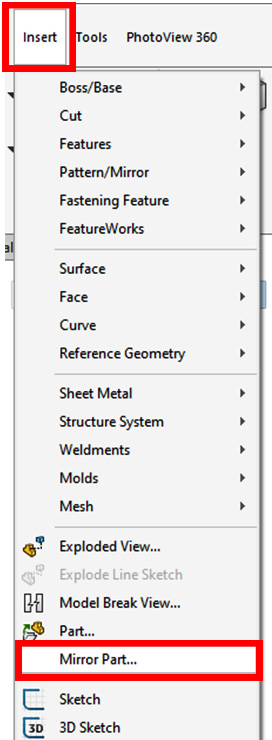
Figure P1.28 – The location of the Mirror Part command
- This will open up a new part with the menu shown in Figure P1.29. This will allow us to pick the elements we want to transfer to the new mirrored part. In our case, we need to transfer Solid bodies. Make sure that box is checked, as shown in the following screenshot:
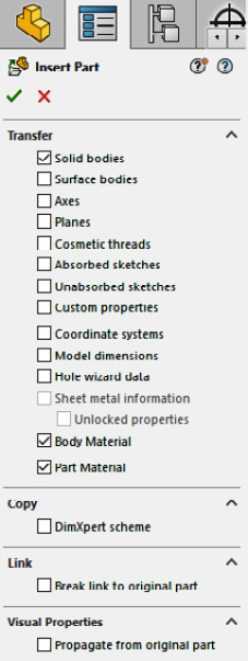
Figure P1.29 – The initial transfer options when creating a mirrored part
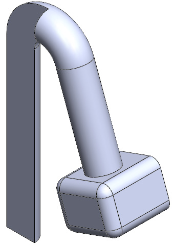
Figure P1.30 – The final mirrored nose link part
- Save the new part with a new name.
By doing this, we have a new mirrored nose link to complement our original one. Keep in mind that the mirrored part takes all its features from the original part. Thus, any changes to the original part will be reflected on the mirrored one. However, new features added to the mirrored part will not be added to the original one.
Now that we have 3D-modeled all the parts, we can join them together in an assembly to form the full pair of glasses.
Creating the assembly
Now that we have all the parts 3D-modeled, we can start exploring the assembly and joining all the parts together. We will do that in this section. We will start by talking about the fixed part, and then explore the different parts and the accompanying mates. The following drawing highlights the fully assembled pair of glasses as well as the names of all the parts:

Figure P1.31 – The pair assembly and its arrangement of parts
The first part we insert into an assembly becomes a fixed part by default. There is no one answer to which part should be used as a fixed part in the assembly. However, a good practice is to select an inherently non-moving part. A good candidate is the bridge.
The following figure highlights the major mates for the pair. You may add more mates as required to get the desired result.
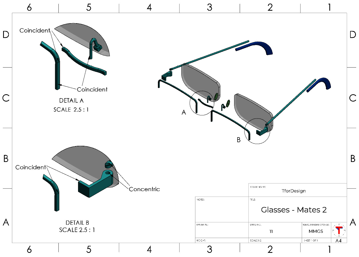
Figure P1.32 – A detailed drawing showing the major assembly metrics
The next figure provides some extra details regarding the assembly, such as the angle of the nose pad in relation to the lens frame:
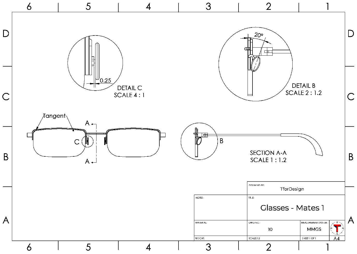
Figure P1.33 – A detailed drawing showing the additional assembly metrics
Putting an assembly together is more open-ended than 3D-modeling a part. So, you can formulate your own way and sequence for joining the different parts together. However, the following figure presents a possible sequence that you can follow if you are unsure where to start. Note that where the mate coincident is the only one mentioned, it was applied more than once.

Figure P1.34 – A possible sequence in building the assembly
By the end of step 8, half of the glasses would be assembled. You can follow steps 2–8 again to assemble the other half. Alternatively, you can use the Mirror Components command to duplicate applicable parts to the other side.
As you are building the assembly, note that the given mates will not fully define the assembly; instead, it will allow some movements that can easily demonstrate the functionality of the glasses. For example, the temple will rotate, keeping one end linked to the connector in a similar mechanism to a standard pair of glasses. You can choose to add additional mates to lock the assembly in a specific position.
By completing the assembly, you have completed the project work to 3D-model a pair of glasses.
Summary
In this project chapter, you worked toward 3D-modeling a set of glasses. To that end, you had to interpret engineering drawings, 3D-model different parts, and then join them together in an assembly. The skills used to complete the project include the essential 3D-modeling skills you will use for any project.
In the coming chapters, we will start addressing more advanced commands and features that will allow us to optimize our 3D-modeling approach and 3D-model more complex geometries faster.