
Chapter 5: Basic Primary One-Sketch Features
In SOLIDWORKS, features are what can turn a 2D sketch into a 3D model. In this chapter, we will move on from 2D sketches and start creating 3D models. We will explore the most basic features, such as extruded boss and extruded cut, fillets, chamfers, and revolved boss and revolved cut. We will study how to apply, modify, and delete features. We will also start creating more complex models by applying multiple features. Each feature that's covered in this chapter requires only one sketch to apply or no sketch at all.
In this chapter, we will cover the following topics:
- Understanding features in SOLIDWORKS
- Understanding and applying extruded boss and cut
- Understanding and applying fillets and chamfers
- Understanding and applying revolved boss and revolved cut
By the end of this chapter, we will be able to create 3D models using the most common features in SOLIDWORKS. Even though the features covered in this chapter are simple, they will enable us to create complex-looking 3D models.
Technical requirements
In this chapter, you will need to have access to SOLIDWORKS.
Check out the following video to see the code in action: https://bit.ly/3oUIyjl
Understanding features in SOLIDWORKS
SOLIDWORKS features are our way of moving from 2D to 3D. Similar to sketches, SOLIDWORKS provides many features that can help us create simple shapes. For more complex shapes, we will have to use more features. In this section, we will discuss SOLIDWORKS features, simple versus complex models, and additional sketch planes.
Understanding SOLIDWORKS features and their role in 3D modeling
Features is the term we use to refer to the tools that allow us to construct 3D models based on sketches. We usually use features directly after sketching to go from two-dimensional sketches to 3D models, which are mostly built based on sketches.
For example, if we were to model a cube, we would follow these steps:
- First, we would create a sketch of a square.
- Then, we would apply a feature in order to make the square into a cube. We do this by extruding it.
The following screenshot illustrates these two steps:
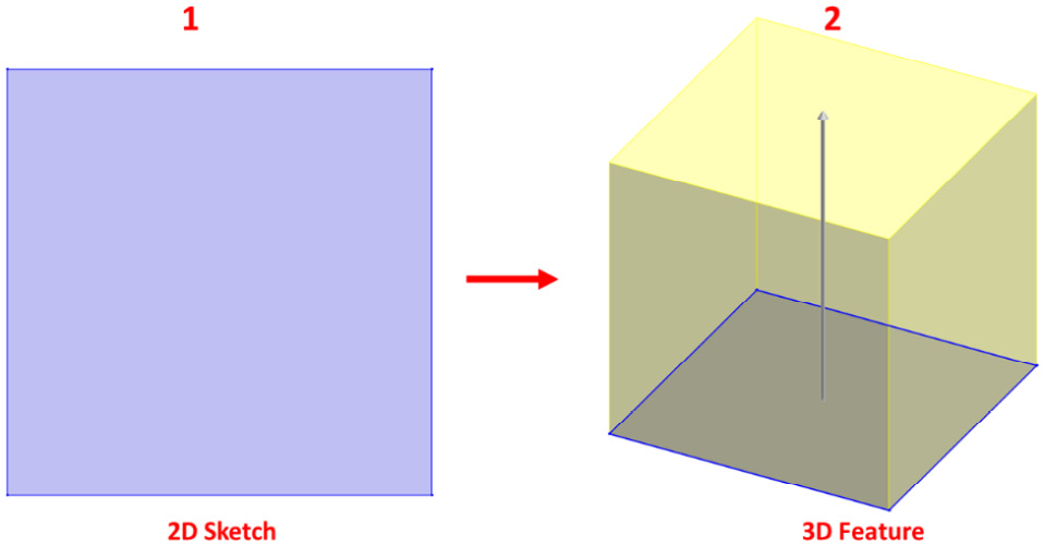
Figure 5.1 – A 2D sketch is used to build a 3D feature
Now that we know what features are, as well as their purpose, we can address how features differ in terms of simple and complex models.
Simple models versus complex models
SOLIDWORKS offers a wide variety of features that can help us easily create different shapes. Most of these features are for simple shapes such as simple hexahedrons (cubes), rotational shapes such as spheres and tubes, and much more. Thus, we will apply more features that build on top of each other to create more complex models.
When we were sketching, we applied and mixed multiple sketch commands to create more complex sketches. This is similar to what we do with features. The more complex the model is, the more features it may require.
To highlight this, take a look at the models shown in the following figure. The one on the left is a simple model of a cube. We only used one feature to create this cube. The model on the right is a turbine rotor. It is a more complex model, and we had to use 11 features to build it:
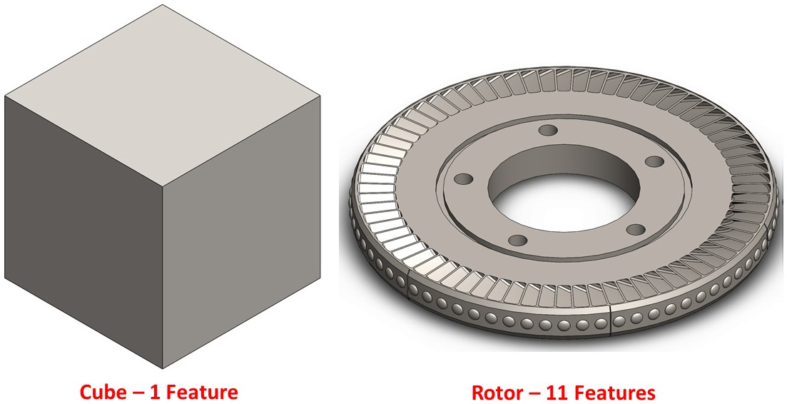
Figure 5.2 – More complex models can require more features to build
As we continue using SOLIDWORKS, we will be able to create more complex models. Now, let's learn about one fundamental aspect of all features – planes.
Sketching planes for features
By default, SOLIDWORKS provides three default planes: the front plane, the top plane, and the right plane. We will use one of these planes to create our first sketch and feature. As we start applying features, these three basic planes may not fullfill our needs for further sketches and features.
Thus, by creating more features, the resulting straight surfaces can also be used as sketching planes. We can use these to create even more sketches and features.
For example, for a new file, we will only have three sketch planes – the default base ones. If we create a cube, each face of the cube will also be a possible sketch plane. Thus, after creating the cube, we will be adding five potential sketch planes for the five new faces of the cube. The following image shows the three base planes, as well as some of the new planes that were created with the new cube. Note that some of the sketch planes may coincide with each other:

Figure 5.3 – A visual representation of the base planes and a cube's surfaces
Tip
Any straight surface can also be used as a sketch plane.
We have just learned what features are, which features are used in complex and simple models, and how sketch planes relate to features. Now, let's explore our first set of features – extruded boss and cut.
Understanding and applying extruded boss and cut
Extruded boss and extruded cut are the most basic and easiest features to apply. They are direct extensions of a sketch and push it into the third dimension. In this section, we will cover what extruded boss and extruded cut are, how to apply them, how to edit them, and how to delete them.
What are extruded boss and extruded cut?
Extruded boss and extruded cut are two of the most basic features we'll use when modeling with SOLIDWORKS. Let's look at them in more detail:
- Extruded boss: This is a direct extension of a sketch that pushes it into the third dimension, resulting in adding materials.
- Extruded cut: This is a direct extension of a sketch that pushes it into the third dimension, resulting in removing/subtracting materials.
From these definitions, you can see that extruded boss and extruded cut are quite similar, but they have opposite effects. Extruded boss adds materials, while extruded cut removes material. The following figure illustrates the effect of the extruded boss feature. Note that we were able to go from a 2D sketch to adding materials to form a cube:
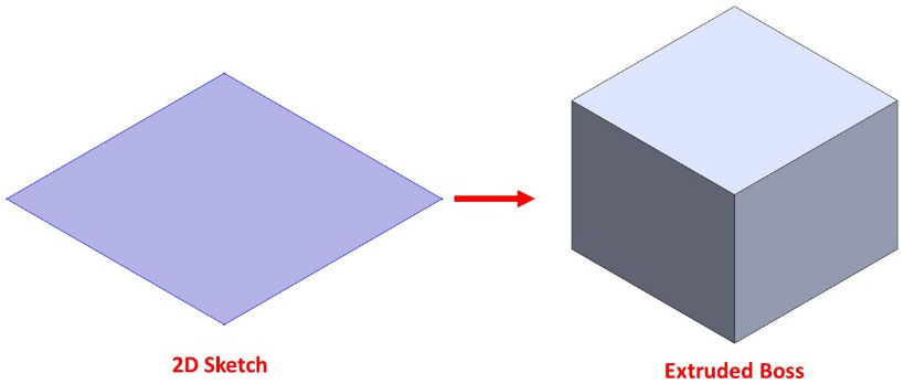
Figure 5.4 – A representation of what the extruded boss feature does
The following figure illustrates the effect of extruded cut. Note that we were able to use a sketch to remove materials:

Figure 5.5 – A representation of what the extruded cut feature does
Let's learn how to apply the extruded boss feature.
Applying extruded boss
In this section, we will discuss how to apply the extruded boss feature. To show this, we will create the model shown in the following figure. We have added annotations for each view, including information about the view's type and its dimensions:
Important Note
We will keep building with the same model as we explore extruded boss and extruded cut. Thus, keep saving the model as we go along.
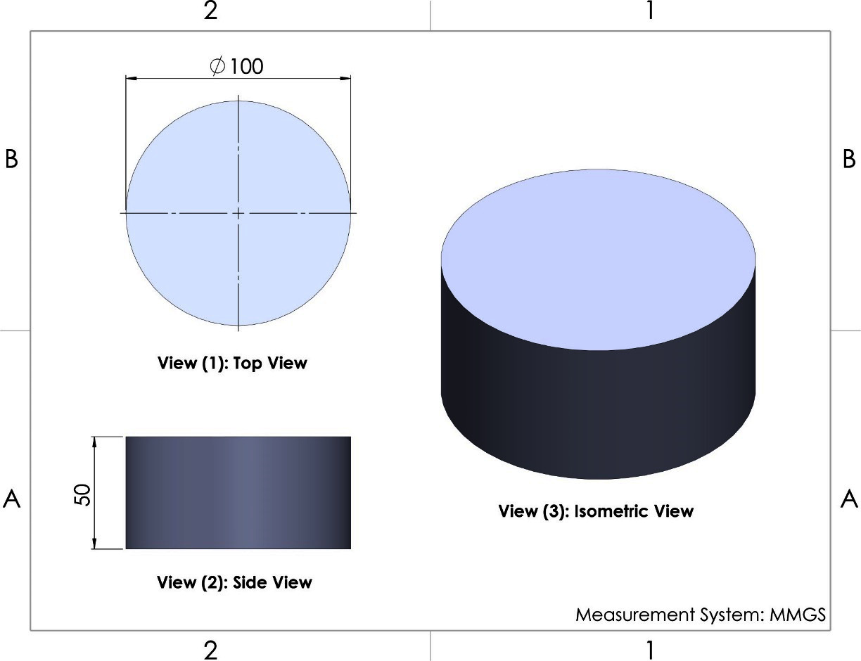
Figure 5.6 – The end shape of the extruded boss exercise
When applying the extruded boss and extruded cut features, we will always start with a 2D sketch and then apply that feature based on that 2D sketch. Thus, for this exercise, we will split each feature application into two stages – the sketching stage and applying the feature stage.
One important aspect to keep in mind is that, as we continue modeling, we will need to plan a strategy when it comes to how to model the targeted object. There is no right or wrong way to create a model. Thus, different people will have different plans for making the same model. It is always good to plan ahead when it comes to creating a model. We can do that by either sketching or writing down our ideas. Since we are taking our first steps toward 3D modeling, we will need to have a brief written plan before we start modeling:
- Planning: We start by creating a circle and then extruding that into a cylinder.
- Sketching: Next, we sketch and fully define a circle with a diameter of 100 mm. We can see this in Figure 5.6, where it says View (1): Top View. The circle will look as follows:
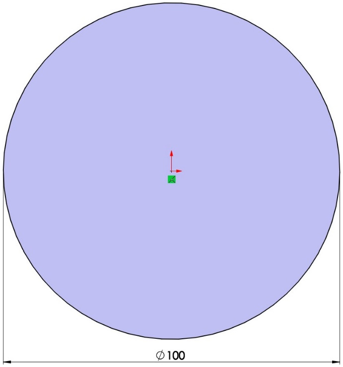
Figure 5.7 – A circular sketch used as a foundation for extruded boss
- Applying the feature: In this example, we will apply the extruded boss feature.
To apply the features, follow these steps:
- Click on the Features tab and select the Extruded Boss/Base command, as shown in the following screenshot. We don't need to exit sketch mode. As soon as we select this command, SOLIDWORKS will understand that we want to apply this feature to the active sketch:
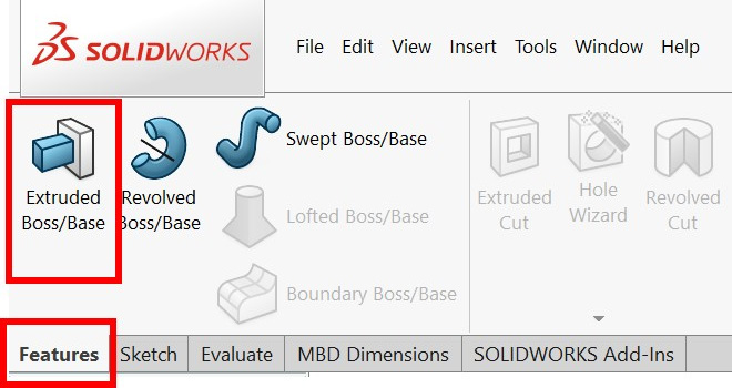
Figure 5.8 – The location of the extruded boss feature
- Once we click on the Extruded Boss/Base command, we will notice that an options panel appears on the left-hand side. The extrusion preview will also appear on the canvas:
Important Note
If we exit the sketch mode before selecting the Extruded Boss/Base command, we can simply select the command and then select the sketch on the canvas.
- Fill out the options in the PropertyManager, as shown in the following screenshot. Fill in the height as 50 mm. The PropertyManager will appear on the left-hand side of the interface:
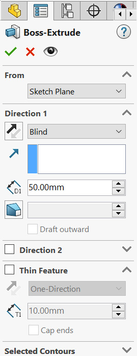
Figure 5.9 – The extruded boss feature setting for this exercise
- Once we've filled in these options, we will see the following preview:
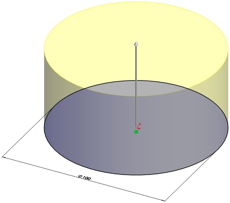
Figure 5.10 – A preview of the extruded boss application
- After adjusting the options for our extrusion, we can click on the green check mark at the top of the PropertyManager panel to apply the extrusion:
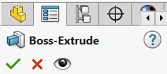
Figure 5.11 – The green check mark on top of the PropertyManager to apply the feature
The result will be the following model:
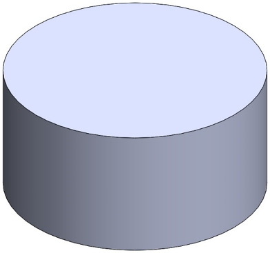
Figure 5.12 – The resulting 3D model after the extrusion
Before we finish looking at the extruded boss feature, let's take a look at options in the PropertyManager. We will look at them based on their listing order, that is, from top to bottom, as shown in the following screenshot. We will start with the options we used in this exercise and then move on and look at the options we didn't use:
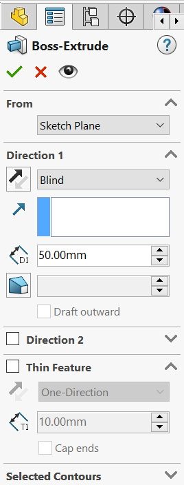
Figure 5.13 – The different options available for the extruded boss feature
The following options are available for the extruded boss feature:
- From: This determines where the extrusion features should start. Since we are still beginners, we will mostly use Sketch Plane. This means that the extrusion will start from the sketch that was used to create it. Other options include starting from Surface, Vertex, and Offset. The first two can't be used in this case because our model doesn't have multiple surfaces and vertices. The last option, Offset, can be used to offset the whole extrusion by a certain distance. You can see the From option on top of the PropertyManager feature, as shown in Figure 5.13.
- Direction 1: This is active by default. Under this heading, we can customize the previewed extrusion that's shown on the canvas. We can hover the mouse over the options to see their full names. The options under Direction 1 are as follows:
a) End Condition: This determines how the extrusion stops. In this exercise, we will only be using the Blind option, which is selected by default. This means that the extrusion will be extended by the dimensions that we indicate. We will explore other end conditions later in the book.
b) Reverse Direction: This is the arrow to the left of End Condition. This can easily reverse the direction of the extrusion from up to down and vice versa.
c) Depth (D1): This determines the depth of the extrusion. In our case, we want the extrusion to be 50 mm deep, so we will input 50 mm.
d) Draft: The icon below Depth is used to draft the extrusion. We can activate drafting by clicking on the icon. We will cover this option at a more advanced level later in this book.
- Direction 2: This is very similar to Direction 1; however, it applies the extrusion in the opposite direction as well. We can use this if we ever want to have different length extrusions in two directions on the sketch. We can simply check this box if we require the second direction. This wasn't needed in our example.
- Thin Feature: This applies an extrusion based on the thin borders of the sketch rather than the enclosed shape. It can be activated by checking the box next to it. If we apply Thin Feature to our circle, we will get a result similar to the one shown in the following figure. Take some time to draw another circle and experiment with Thin Feature:
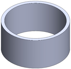
Figure 5.14 – A sketch of one circle can translate to a ring using the thin feature
- Selected Contours: This can be used if we have more than one enclosed area. Then, we can select which ones we want to apply the extrusion to. An example of a sketch with more than one enclosed area is highlighted in the following figure, which has three enclosed areas:
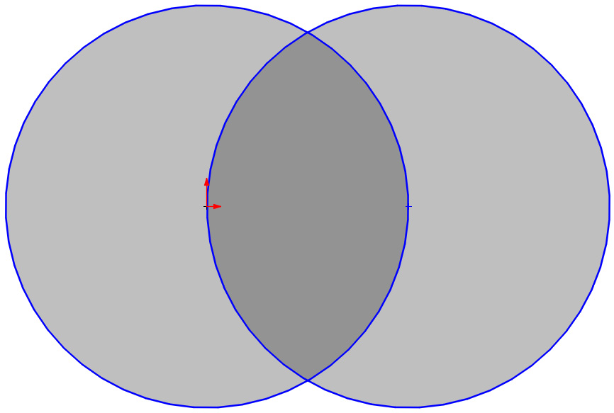
Figure 5.15 – A sketch with three enclosed areas
This concludes the section on creating the requested cylinder using the extruded boss feature. We learned about the following topics:
- The sequence we follow to create a model using features, that is, planning, sketching, and applying features
- How to relate a sketch to the extruded boss feature
- How to set up the extruded boss feature and apply the extrusion
Now that we know about the extruded boss feature, we will look at the extruded cut feature.
Applying extruded cut and building on existing features
In this section, we will discuss how to apply the extruded cut feature. The extruded cut feature is very similar to the extruded boss feature in terms of the options that are available to us. Due to this, we will explain them in less detail. We will build upon the model we created previously with extruded boss so that we can learn how to build upon existing features. To demonstrate this, we will create the following model:
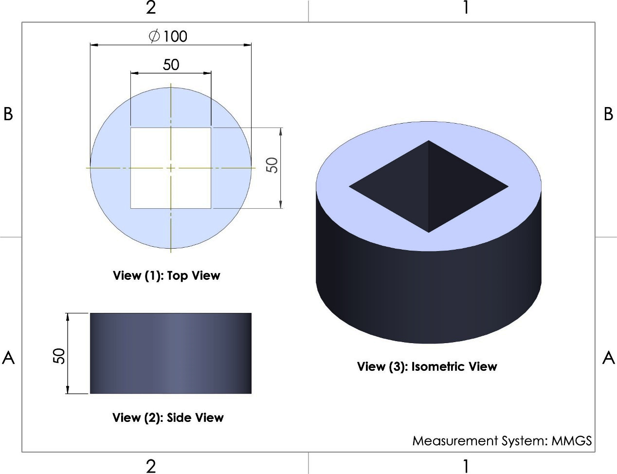
Figure 5.16 – The end model of the extruded cut exercise
Note that, in the preceding model, we are only applying an extra cut over the cylinder that we created with the extruded boss feature. Thus, we will start from the cylinder we created earlier and create an extra extruded cut. We will go through the following phases to do so:
- Planning: We will draw a square on top of the cylinder and apply it using the extruded cut feature.
- Sketching: The cutoff shape is a square, and so we will sketch a square on the top surface of the cylinder. Note that the top surface is not a default sketch plane. However, it is a straight surface, which means we can use it as a sketch plane.
- Applying the feature: When we have our sketch, we can apply our feature; in this case, this is extruded cut.
Follow these steps to create the sketch:
- Select the top surface of the cylinder and click on the Sketch command, as shown in the following screenshot. We can also do this the other way around, that is, select the Sketch command first and then select the surface we want to sketch on:
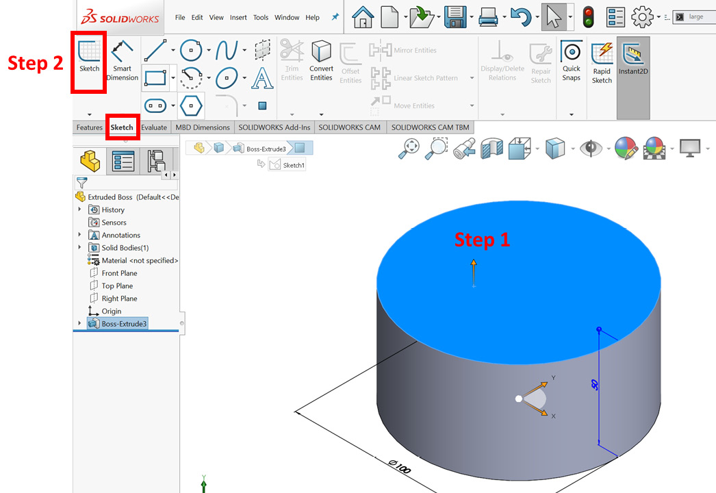
Figure 5.17 – A visual demo of steps 1 and 2
Now we need to start sketching. However, we may have a tilted view of our new sketch surface, which will make it harder for us to sketch. We can adjust our view so that it's normal to the sketch surface to make it easier to sketch. To do that, we can right-click on the new sketch at the bottom of the design tree and select Normal To, as shown in the following screenshot:
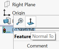
Figure 5.18 – The Normal To command changes our view to facing the sketch plane
This will change our view of the canvas so that it's facing the sketch surface. If we select Normal To again, the model will flip 180 degrees.
- Sketch and fully define the required square, as shown in the following figure. The side of the square is 50 mm in length, as shown by View (1): Top View in Figure 5.16 at the beginning of this section:
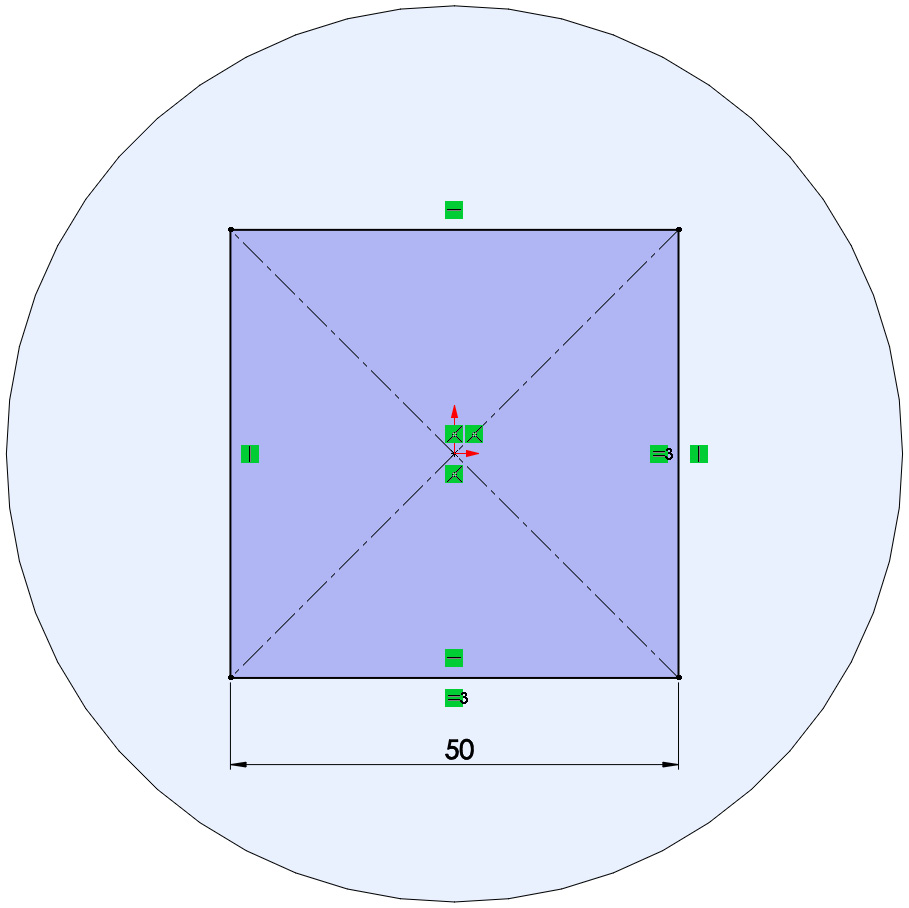
Figure 5.19 – The fully defined sketch for the extruded cut feature
Now that we have our sketch, we can apply our extruded cut feature.
- Select the Features tab and select the Extruded Cut command, as shown in the following screenshot. (As with the extruded boss feature, we don't need to exit sketch mode.) As soon as we select the command, SOLIDWORKS will interpret that we want to apply the feature to the active sketch:
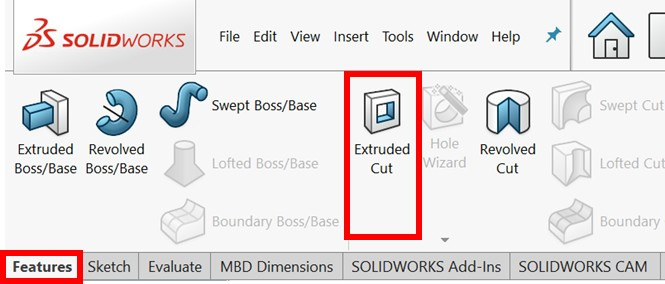
Figure 5.20 – The location of the extruded cut feature
- Set the options in the PropertyManager as follows:
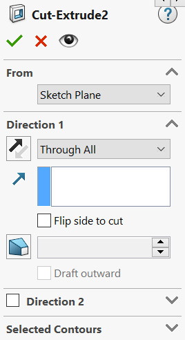
Figure 5.21 – The PropertyManager setting for the extruded cut feature
- As with the extruded boss feature, we will also see a preview of the cut appear on the canvas. This preview is shown in the following figure:
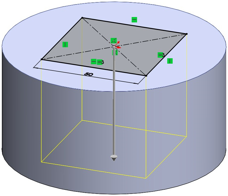
Figure 5.22 – A preview of the extruded cut
Note that the options that are shown in the PropertyManager for the extruded cut feature are almost the same as the options for the extruded boss feature. We will only elaborate on those that are highlighted in the following screenshot:
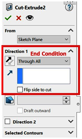
Figure 5.23 – The end condition as displayed in the PropertyManager
Let's take a look at these options in more detail:
- End Condition: Many end conditions are the same as for the extruded boss feature. By default, the end condition is usually Blind. However, in our case, we changed it to Through All. The Through All end condition means that the cut will extend to the end of the model, which is what we want. We can also get the same result by using the Blind end condition and setting the depth of the cut to 50 mm or more. To change the end condition, click on the drop-down menu and select the desired condition.
- Flip side to cut: Checking this option will turn the cut part around. In our example, if we have this option checked, we will keep the contained square and delete everything else. Having this option unchecked will delete the contained square and keep everything else. Experiment with this option to understand what it does.
- Click the green check mark at the top of the PropertyManager to apply the extruded cut feature. We will end up with the following model:
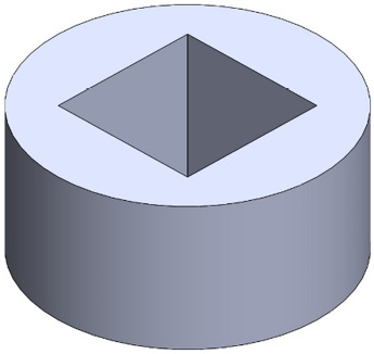
Figure 5.24 – The final model after applying the extruded cut feature
Recall that after entering a sketch, we switched the view to normal for that sketch to make it easier to deal with. We can have the software auto-rotate the view to normal to sketch a plane on sketch creation and edits by enabling that from the system options. You can find the option by going to Tools and then Options. Under the System Options, click on Sketch, and then find the Auto-rotate view normal to sketch plane on sketch creation and sketch edit option, as shown in the following figure:
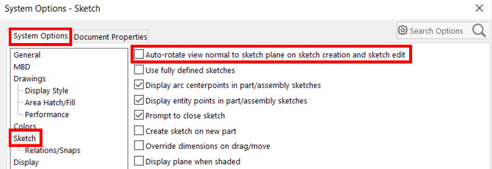
Figure 5.25 – Auto-rotate to a normal view
This concludes using the extruded cut feature. In this section, we covered the following topics:
- How to sketch over existing surfaces
- How to apply the extruded cut feature
Now that we know how to apply the extruded boss and cut features, we will learn how to modify and delete them.
Modifying and deleting extruded boss and extruded cut
Often, we apply a feature and then need to edit it or delete it. In this section, we will address how to edit and delete features. To illustrate this, we will apply the modifications shown in the following figure to the model we created earlier:
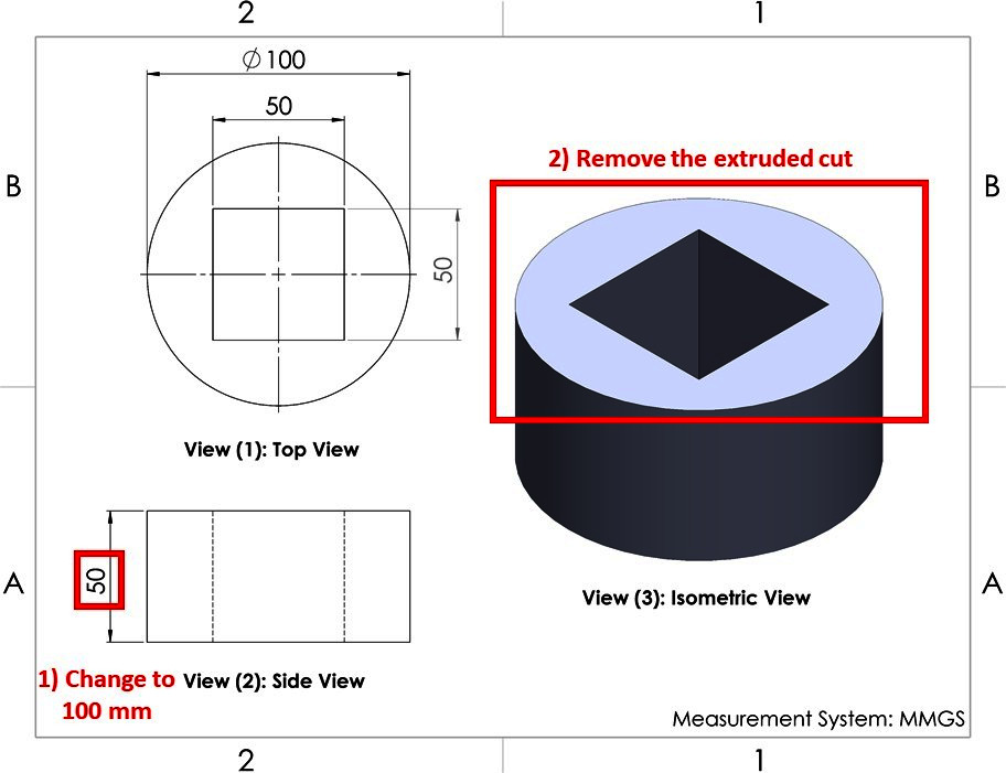
Figure 5.26 – The changes to the model to be applied in this exercise
As shown in the preceding figure, the changes that we are going to make are as follows:
- Changing the height of the cylinder from 50 mm to 100 mm
- Removing the extruded cut that goes through the cylinder
Let's go ahead and apply these changes.
Editing a feature – changing the height of the cylinder from 50 mm to 100 mm
To edit an implemented feature, we can right-click (or left-click) on it on the design tree and select the Edit Feature option. In this case, we want to edit the boss extrude feature we applied. Thus, we can right-click on the first Boss-Extrude feature and select Edit Feature, as shown in the following screenshot:
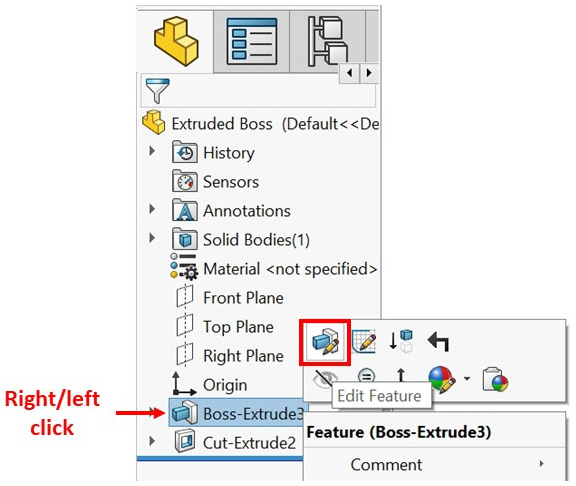
Figure 5.27 – The Edit Feature command as shown in the SOLIDWORKS interface
Once we select Edit Feature, the extruded boss features will be shown on the left, while a preview of the extruded boss feature will be shown on the right. Note that the preview doesn't show the extruded cut feature because it is located lower in the design tree. From the available options, we can change D1 from 50 to 100, as shown in the following screenshot. After making this change, we can click on the green check mark to implement it:

Figure 5.28 – A feature can be edited by directly editing its PropertyManager
Now our cylinder will become longer, as shown in the following figure. If the shape of the model failed to update, try clicking on the traffic light (Rebuild) icon at the top of the SOLIDWORKS interface or use the Ctrl + B shortcut:
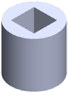
Figure 5.29 – The shape of our model after editing the extruded boss feature
This concludes how to edit a feature. Now, let's look at deleting a feature.
Deleting a feature – removing the extruded cut feature that goes through the cylinder
To delete a feature, right-click on a feature in the design tree and select the Delete… option. In this case, we want to delete the extruded cut feature. Thus, we can right-click on it and select Delete..., as shown in the following screenshot:
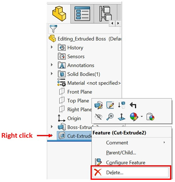
Figure 5.30 – Features can be deleted with the Delete… command
Once we've selected Delete…, we will get the following message, asking us to confirm that we want to delete the feature. The message will specify the item to be deleted, which in our case is Cut-Extrude2 (Feature). It will also specify any dependent items that will be deleted with the feature; there are none in this case. We will cover dependent items at a more advanced level later in this book. We can click Yes to confirm that we want to delete the feature:
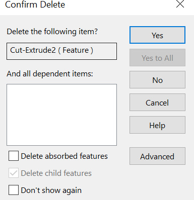
Figure 5.31 – A conformation box appears when deleting a feature
Now, we will end up with the following model. Note that we only deleted the feature, so the sketch will still remain in the model for us to use for any other purpose, as shown in the following figure:

Figure 5.32 – The sketch still remains even though its feature was deleted
If we want to delete both the feature and its sketch, we can check the following Delete absorbed features option, as shown in Figure 5.31, when deleting the feature.
Tip
We can delete the feature by directly selecting it on the design tree and pressing Delete on the keyboard.
This concludes the sections on editing and deleting features. Every feature can be edited and deleted in the same way.
As designers and 3D modelers, we will be faced with many situations where we receive models from other individuals and are asked to edit them. Also, we ourselves will modify our models as part of improvement cycles. Thus, it is very important for us to know how to modify models. As our SOLIDWORKS skills grow, we will pay special attention to modifying models, especially pre-existing ones.
We have just learned about our first set of features, that is, extruded boss and extruded cut. We learned how to apply them and how to modify them. Now, we will move on to another set of features – fillets and chamfers.
Understanding and applying fillets and chamfers
Fillets and chamfers are used to modify edges and vertices on our models by making them less sharp. If we look at everyday objects around us, such as phones, laptops, and furniture, we will notice the common use of small fillets and chamfers on the edges. In this section, we will discuss what fillets and chamfers are, how to apply them, and how to modify them.
Understanding fillets and chamfers
Fillets and chamfers are modifications that are made to the edges and vertices of our models. A fillet is a curved surface defined by a radius, while a chamfer is a transitional straight surface defined by lengths and angles. They help remove sharp edges and turn them into softer ones in order to provide a safer product or a better user experience. They are similar to fillets and chamfers in sketching. The following figure illustrates the effect of the fillet feature:
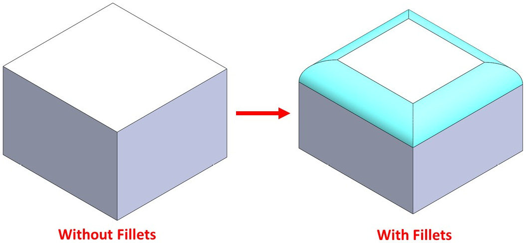
Figure 5.33 – Edges with and without fillets
The following figure illustrates the effect of the chamfer feature:
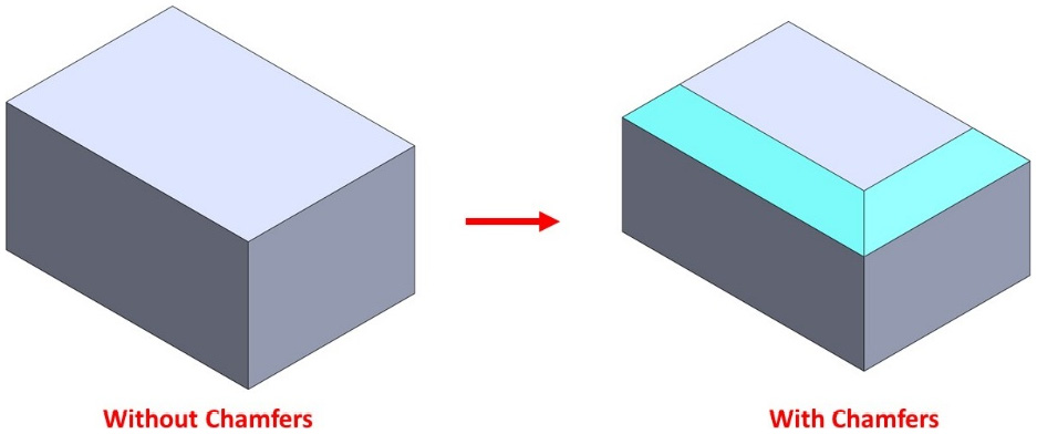
Figure 5.34 – Edges with and without chamfers
Note that fillets and chamfers can only be applied to existing features. In the preceding figure, we explored the extruded boss feature first, and then we were able to apply fillets or chamfers. Also, to apply fillets and chamfers, we don't need to start with a 2D sketch.
Now that we know what fillets and chamfers are, we can start using them in SOLIDWORKS.
Applying fillets
In this section, we will discuss how to apply the fillet feature. To show this, we will create the model shown as follows:
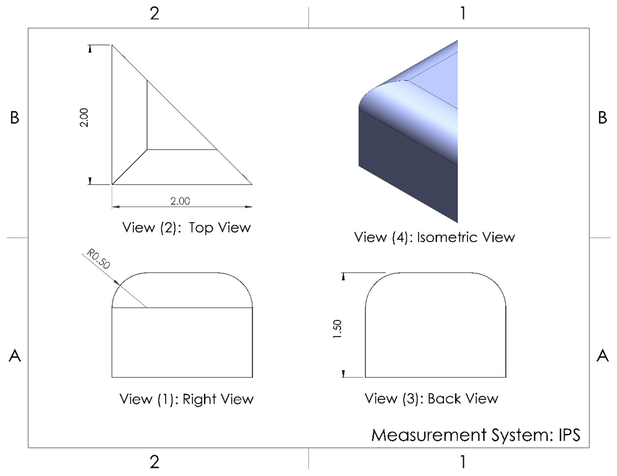
Figure 5.35 – The 3D model we are making for this exercise
As usual, we will start with planning, sketching, and then applying a feature:
- Planning: Here, we will create a triangular prism and then apply fillets to the top edges.
- Sketch: We will sketch and fully define a triangle, as shown by the Top View view in the preceding figure.
- Feature: We will apply the extruded boss feature by 1.5 inches, as shown by the Back View view in the preceding figure. This will result in a triangular prism that looks as follows:

Figure 5.36 – The base triangular prism we will use to apply the fillet
To apply the fillet feature, select the Fillet command, as shown in the following screenshot:
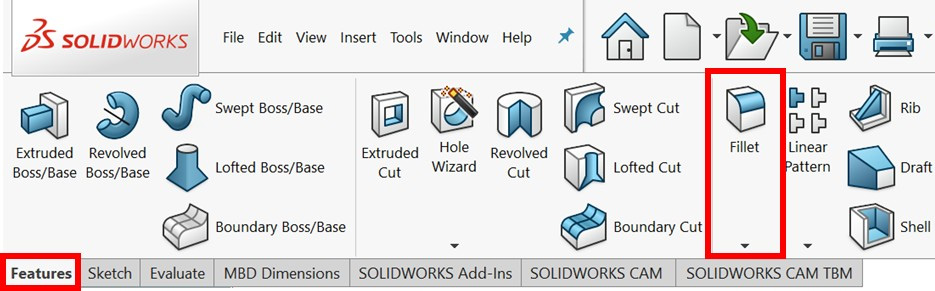
Figure 5.37 – The location of the Fillet command
Select Edge<1> and Edge<2>, which have fillets applied to them. Adjust the Fillet options, as shown in the following screenshot showing the PropertyManager:
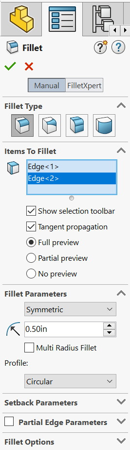
Figure 5.38 – The fillet feature PropertyManager
The following is a brief explanation of the options that we used in this exercise:
- Fillet Type: This specifies the type of fillet we're using. The first type is the constant size fillet, which we are using in this exercise. As we are only beginners, we will only use this type.
- Items to Fillet: This highlights where the fillet will be applied. In our example, we're applying it to Edge <1> and Edge <2>. We can use this window to remove edges from the selection if we've added one by mistake. For the selection, we can select individual edges or faces. Selecting a face will apply the fillet to all the edges related to that face.
- Show selection toolbar: If this option is checked, then we can select an edge; a small selection toolbar will appear with some shortcuts that we can use to select where we want to apply the fillet. The toolbar looks as follows. Since the selection toolbar only contains selection shortcuts, we can disregard it for now and start using it later, once we are comfortable with the different selections it provides:
Figure 5.39 – The selection toolbar is an easy way to select the edges to apply the fillet to
- Tangent propagation: This only applies if there's more than one edge and they are tangential to each other, for example, two curved edges that have a tangent relationship with each other. In the case of our triangular prism, none of the edges are tangent to each other. Thus, selecting or deselecting this option will not make any difference.
- Full preview, Partial preview, and No preview: These options decide on the type of fillet preview we can see when we are making the shape. Selecting Full preview will show us what the fillet looks like in its entirety, whereas selecting No preview won't show it at all.
- Fillet Parameters: Here, we have two options, Symmetric and Asymmetric. A Symmetric fillet is a uniform fillet in which we only need to define one radius. An Asymmetric fillet, on the other hand, has different curvatures on each side and requires us to define more than one dimension.
- Radius: Here, we can input a numerical value for the fillet radius. In this exercise, it is 0.5 inches, as shown by View (1): Right View in the figure at the beginning of this section.
- Multi Radius Fillet: Clicking this option will allow us to determine a different radius for different edges. For example, if we want the fillet radius for Edge <1> to be different from the fillet radius for Edge <2>, we can use this option.
- Profile: This determines the profile of the fillet. The Circular profile option projects the fillet profile as a quarter of a circle. Other options include Conic Rho, Conic Radius, and Curvature continuous.
We won't be using the Setback Parameter, Partial Edge Parameter, and Fillet Options just yet. While we are here, take some time to combine some of the preceding options and look at the result in the canvas preview. Once done, click on the green check mark at the top of the Options tab to apply the fillet. We should get the following shape:
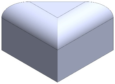
Figure 5.40 – The final 3D model after applying the fillet
This concludes how to apply fillets. In this section, we covered the following topics:
- How to apply fillets in SOLIDWORKS
- The different options we can use to define fillets in SOLIDWORKS
Now that we know how to apply fillets, let's learn how to apply chamfers.
Applying chamfers
In this section, we will discuss how to apply the chamfer feature. To do this, we will create the model shown in the following figure:
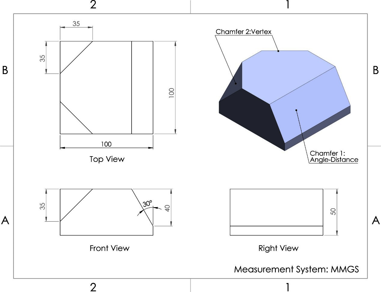
Figure 5.41 – The 3D model we are making with this exercise
The preceding figure specifies two different types of chamfers, each with different specifications. In SOLIDWORKS 2022, there are five different types of chamfers, based on how they are defined. The following table illustrates the angle-distance, distance-distance, and vertex chamfer types:
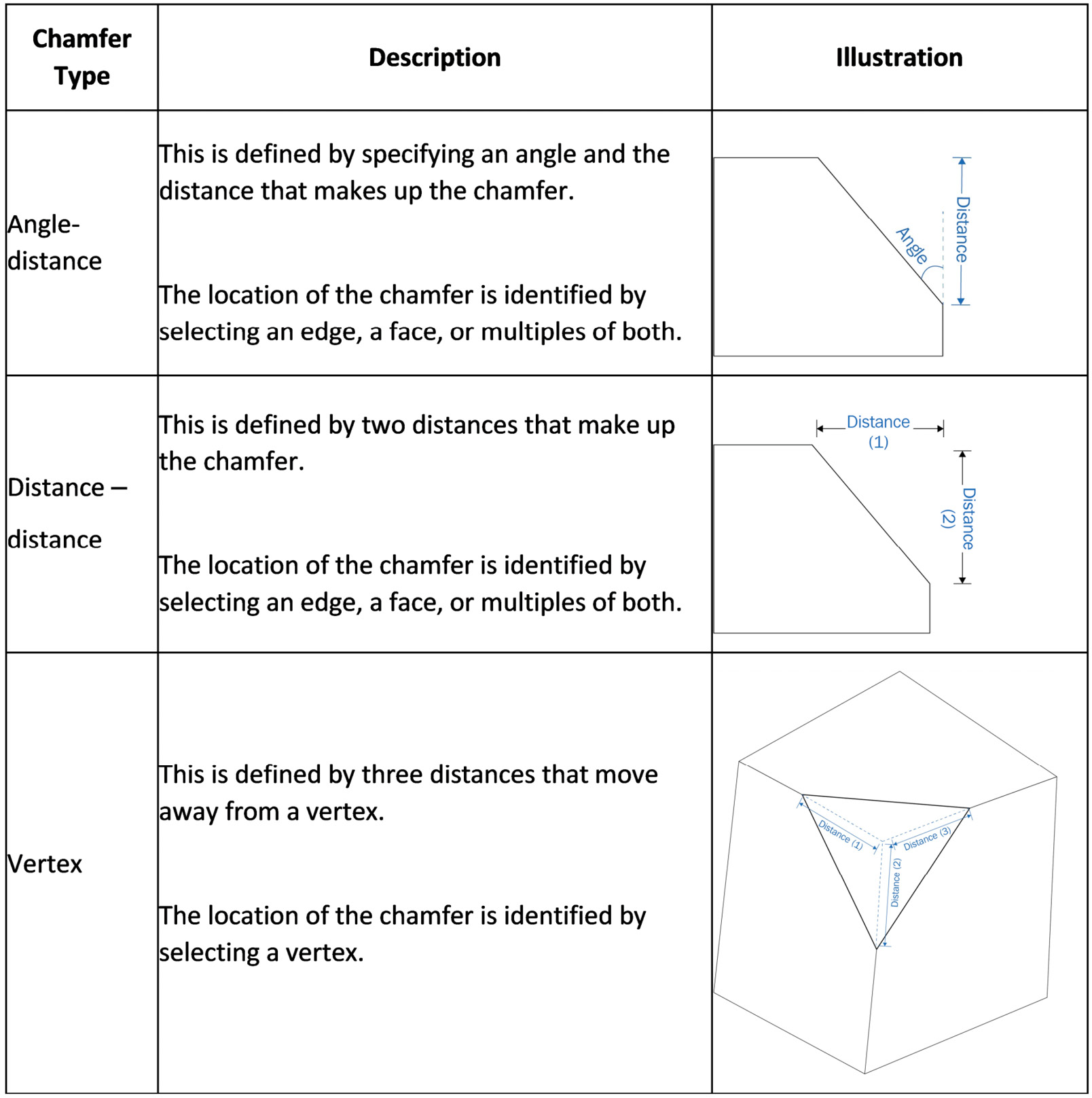
Figure 5.42 – Illustrations of the angle-distance, distance-distance, and vertex chamfer types
The following table illustrates the offset face and face-face chamfer types. Each chamfer type is defined differently giving us different options to help maintain our required design intent:
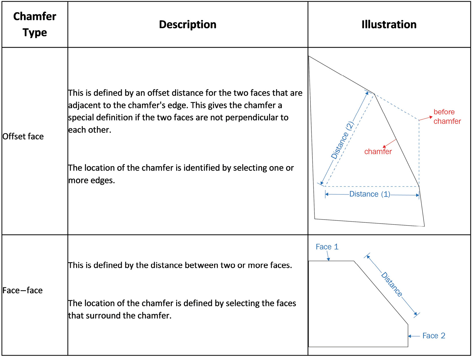
Figure 5.43 – Illustrations of the offset face and face-face chamfer types
The model we are going to create uses two types of chamfers, angle-distance and vertex. To create the chamfer, we will follow our usual procedure, where we start by planning, then creating sketches, and then applying a feature:
- Planning: Here, we will create a rectangular prism and then create an angle- distance chamfer, followed by two vertex chamfers.
- Sketch: We will sketch and fully define a 100 x 100 mm square, as shown in the top view of the diagram at the beginning of this section.
- Feature: We will be applying the extruded boss feature and extruding the square by 50 mm, as shown in the right view of the diagram at the beginning of this section. At this point, we will have the following rectangular prism:
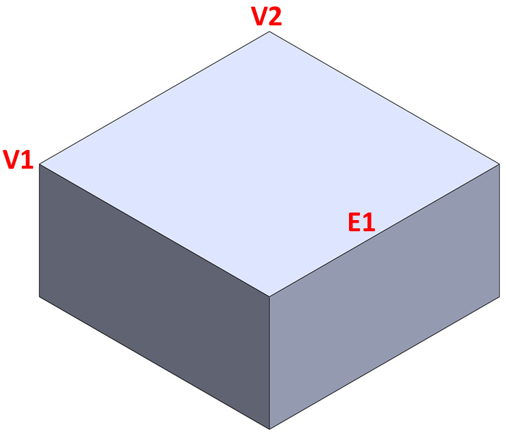
Figure 5.44 – The base rectangular prism we will use to apply the chamfers to
To apply angle-distance chamfers, follow these steps:
- To apply the chamfer feature, select the Chamfer command, as shown in the following screenshot. The command can also be accessed from the drop-down menu, under the Fillet command:

Figure 5.45 – The location of the Chamfer command
- Set up the chamfer's options in the PropertyManager as follows. Some options that are available for the chamfer feature are the same as for the fillet feature, so we won't go over them in as much detail here:
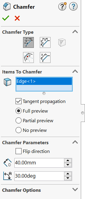
Figure 5.46 – Chamfer's PropertyManager
The following is a brief description of the options that we used in this exercise:
- Chamfer Type: From here, we can select one of the five types of chamfers, as specified in the preceding table. We can hover over each one to see their names. For our first chamfer, we will use the angle-distance chamfer.
- Items To Chamfer: This specifies the location of the chamfer. We can apply the angle-distance chamfer by selecting edge 1 (E1), as highlighted in the following rectangular prism. If we select another edge or face by mistake, we can remove it by deleting it from the list under Items to Chamfer, as shown in the PropertyManager:

Figure 5.47 – Select edge 1 (E1) to apply the angle-distance chamfer to
- Tangent propagation: This works the same as for fillets. Checking this option will propagate the chamfer across any edges that are tangent to each other. In our case, this option will not make a difference, as there are no other edges that have a tangent relationship to our selected edge.
- Full preview, partial preview, and no preview: This is similar to the option for fillets. This can determine what our chamfer's preview looks like on the canvas.
- Flip direction: This will flip the location of the defining angle and distance.
- Distance (D): This value will determine the distance value of our chamfer. In this exercise, the distance is 40 mm.
- Angle (A): This value will determine the angle value of our chamfer. In this exercise, the angle is 30 degrees.
Tip
While you are here, play around and mix these different options to understand their effects.
- Click on the green check mark to apply the chamfer. After applying the chamfer, we should have the following model:
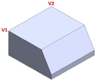
Figure 5.48 – The shape of the 3D model after applying the angle-distance chamfer to E1
At this point, our model has one chamfer of the angle-distance type. Now, we will apply the other two chamfers, which are vertex types. To apply a vertex chamfer, follow these steps:
- Select the Chamfer command from the command bar to apply a second chamfer.
- Set up the chamfer's options as follows in the PropertyManager:

Figure 5.49 – The chamfer PropertyManager for the vertex chamfer type
Here is a brief description of some of the special features we can apply to the vertex chamfer feature:
- Chamfer Type: From here, we select the type of chamfer we want to create; in this case, we want to create a vertex chamfer.
- Items To Chamfer: Select V1 in the canvas to locate the chamfer. Note that, when using the vertex chamfer, we can only apply chamfers to one vertex at a time. In other words, we can only select one vertex in Items To Chamfer.
- Equal distance: The vertex chamfer can be defined with three distances that extend away from the vertex into the edges it consists of (refer to the preceding table regarding chamfer types). Checking this option will make all three distances equal, so we only need to input one dimension. If we uncheck this option, we will need to enter three different distances.
- Distance (D): This value will determine the distance of the chamfer. In this exercise, the distance is 35 mm in all three directions.
- Click on the green check mark to apply the chamfer. After applying the chamfer, we should have the following model:
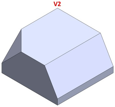
Figure 5.50 – The 3D model after applying the vertex chamfer
- Now, we can repeat steps 1–3 for V2 to apply the second vertex chamfer. After repeating those steps, we will have the final model. This will look as follows:
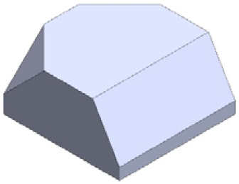
Figure 5.51 – The final model after applying the two vertex chamfers
This concludes how to apply chamfers. In this section, we discussed the following topics:
- The five different types of chamfers, as well as how are they defined and located
- How to apply different types of chamfers in SOLIDWORKS
- The different options we can use to define chamfers in SOLIDWORKS
At this point, we know how to apply fillets and chamfers. Now, let's learn how to modify them.
Modifying fillets and chamfers
To edit or delete a fillet or chamfer, we can follow the same procedure that we followed to edit and delete the extruded boss and cut features. In fact, every feature can be modified in the same way. Here, we right-click on a feature in the design tree and then select Edit to edit it or Delete to delete it.
One special aspect when it comes to modifying chamfers is that there are some limitations between switching from one chamfer type to another. For example, if we modify an angle-distance chamfer, we won't have the option to change the type in order to offset the face. If we are faced with such a limitation, we can simply delete the chamfer and start again with a new one.
Applying partial fillets and chamfers
So far, we talked about making fillets and chamfers that extend to a full edge. However, we can also apply partial fillets and chamfers that are only applied to a specific section of an edge. Let's talk about those here. To do this, we are going to create the following 3D model:

Figure 5.52 – The 3D model we are making with this exercise
We are going to create it in three phases, as follows:
- Creating the rectangular prism
- Applying the partial fillet
- Applying the partial chamfer
The first stage is simple; you can start by sketching a 100 mm square, then extrude it by 50 mm using the extruded boss feature. We are already familiar with applying extruded boss, as shown in the following figure:
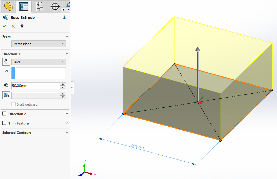
Figure 5.53 – The first step is to extrude the base square by 50 mm
Now that we have our base rectangular prism, we can start applying the partial fillet and chamfers. We will start by applying the fillet.
Applying a partial fillet
To apply a partial fillet, we can follow these steps:
- Select the Fillet command. Then, under Fillet Type, select Constant Size Fillet, select an edge to apply the fillet to, and set the parameters to Symmetric with the radius being 30 mm, as shown in the following screenshot:
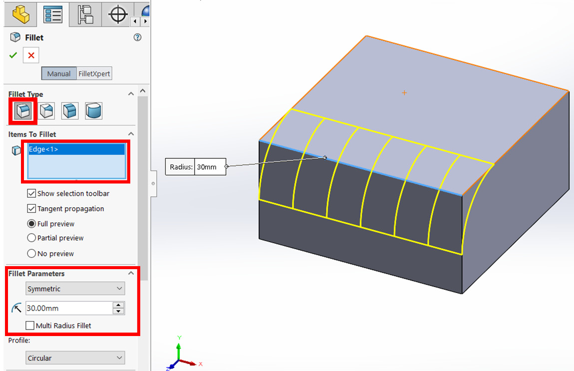
Figure 5.54 – The fillet preview and the PropertyManager applying a full fillet
Important Note
Partial fillets can only be applied to the Contact Size Fillet type.
- Scroll to the bottom of the fillet PropertyManager, and check the Partial Edge Parameters option.
- Set the start condition to Distance Offset and input 30 mm, as shown in the following screenshot:
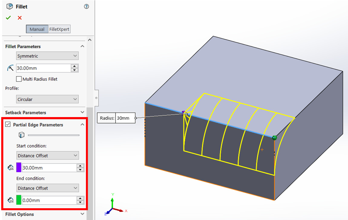
Figure 5.55 – The preview and the PropertyManager applying the fillet to a partial edge
- Click on the green check mark on top of the PropertyManager to apply the partial fillet.
Apart from the Distance Offset start and end conditions, there are another two conditions that can be used. Let's explore them:
- Percentage offset: This allows you to offset the fillet by a certain percentage in relation to the edge.
- Reference offset: This allows you to offset the fillet in relation to an added reference. For example, you can sketch a point on the edge and then use it as a reference to the start or end of the partial fillet.
Tip
While you are here, take some time to experiment with the different types of start and end conditions.
Now that we know how to apply a partial fillet, let's move to apply a partial chamfer to our model.
Applying a partial chamfer
With a few exceptions, applying a partial chamfer follows a similar procedure to applying a partial fillet. We can follow these steps:
- Select the Chamfer command.
- Under Chamfer Type, select the Offset Face type, select an edge to apply the chamfer to, and set the parameters to Symmetric with the distance being 25 mm, as shown in the following screenshot:

Figure 5.56 – The full chamfer preview and its PropertyManager
Important Note
Partial chamfers can only be applied to the Offset Face type.
- Scroll to the bottom of the fillet PropertyManager and check the Partial Edge Parameters option.
- Set the start condition and end condition to Distance Offset and input 10 mm for both, as shown in the following screenshot:

Figure 5.57 – The partial chamfer preview and its PropertyManager
- Click on the green check mart to apply the partial chamfer.
This concludes this section on fillets and chamfers. In this section, we have learned how to apply them and how to modify them. Now, we can start learning about another feature set – revolved boss and revolved cut.
Understanding and applying revolved boss and revolved cut
Revolved boss and revolved cut are two of the most common features in SOLIDWORKS and are also easy to apply. They capitalize on rotational movements to add or remove materials. In this section, we will discuss what revolved boss and revolved cut are, how to apply them, and how to modify them.
What are revolved boss and revolved cut?
Revolved boss and revolved cut are among the most basic features in SOLIDWORKS. Let's explain them in more detail:
- Revolved boss: This adds materials by rotating a sketched shape around an axis.
- Revolved cut: This removes materials by rotating a sketched shape around an axis.
From these definitions, we can see that revolved boss and cut are similar. However, they have the opposite effect. Revolved boss adds materials, while revolved cut removes materials. The following figure illustrates the effect of the revolved boss feature:

Figure 5.58 – An illustration of what the revolved boss feature can do
The following figure illustrates the effect of the Revolved Cut feature:
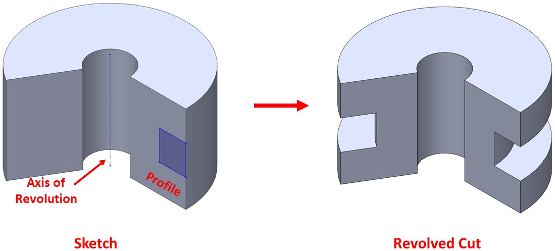
Figure 5.59 – An illustration of what the revolved cut feature can do
As we can see, two elements are required if we want to apply revolved boss and revolved cut – a profile and an axis of revolution. We have to sketch both of them in sketch mode before we can apply our features.
Important Note
The axis of revolution can also be part of the profile.
Now that we know what the revolved boss and revolved cut features are, we will learn how to apply them.
Applying revolved boss
The revolved boss feature adds materials by revolving a sketch around an axis of revolution. To show you how to apply the revolved boss feature, we will create the following model. Now that we are using more and more features, we will start to notice that we use the same options repeatedly. For example, when applying the revolved boss, we notice that most options are the same ones that we use while applying extruded boss. Therefore, we won't explain these again here:
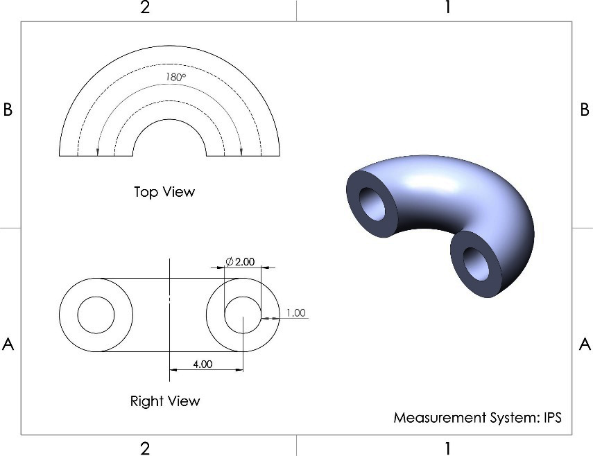
Figure 5.60 – The 3D model we are building in this exercise
As usual, we will follow our standard procedure planning, sketching, and applying features:
- Planning: Here, we'll draw the profile shown in the right view of the preceding drawing, and then we'll rotate that by 180 degrees.
- Sketching: Here, we're going to sketch the profile highlighted in Right View using the right plane. This includes using the axis of revolution. Our sketch should look as follows:
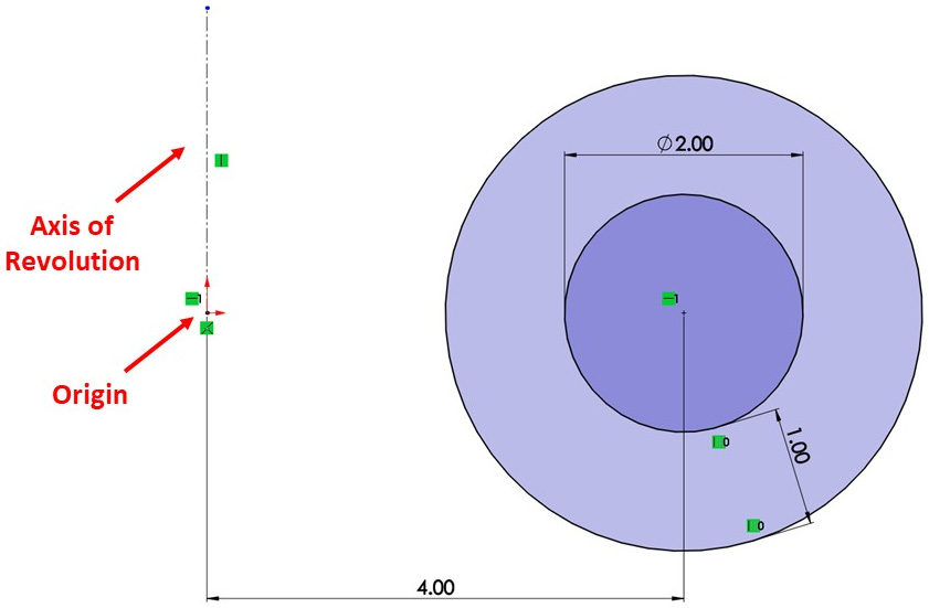
Figure 5.61 – The sketch used to apply the revolved boss feature
To apply the revolved boss feature, follow these steps:
- Select the Revolved Boss/Base command from the Features command bar. We don't need to exit the sketch to select the command. However, if we do exit the sketch for whatever reason, we can select the Revolved Boss/Base command and then select the sketch we want to apply it to:
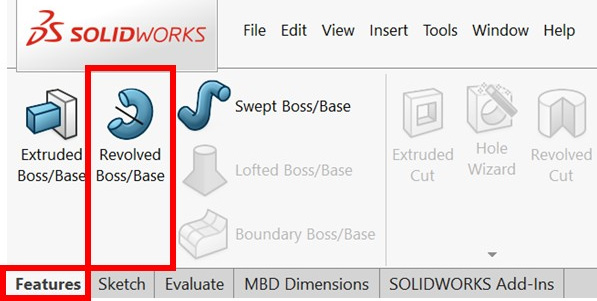
Figure 5.62 – The location of the revolved boss feature

Figure 5.63 – The revolved boss PropertyManager
Here is a brief description of the unique options that can be used with the revolved feature:
- Axis of Revolution: This can be any straight line located on the canvas. This axis will be used to apply the feature by rotating the sketch around that axis. In our exercise, we will select the centerline indicated in the preceding figure as the axis of revolution.
- End Condition: This provides a few options regarding how the revolution will stop. In this exercise, we will use the Blind condition. By doing this, we will decide on the end of the revolution by determining the angle of rotation.
- Reverse Direction: This is the two curved arrows next to the end condition field. Clicking on this icon will reverse the rotation direction of the revolved boss.
- Angle (A1): This determines when the revolution stops. In this exercise, the revolution will stop at 180 degrees.
- Since we're setting the feature's options, we will be able to see a preview of the feature on the canvas. This will look as follows:
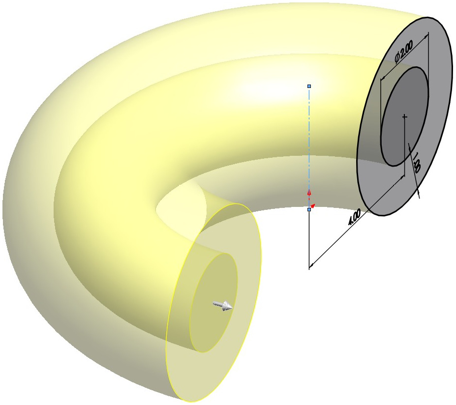
Figure 5.64 – A preview of the revolved boss feature
The rest of the options (Direction 2, Thin Feature, and Selected Contours) were explained when we look at the extruded boss feature. They have the same functionality.
- To apply the revolved boss feature, we can click on the green check mark at the top of the Options panel. The resulting model should look as follows:

Figure 5.65 – The final shape after applying revolved boss
This concludes how to use the revolved boss feature. In this section, we discussed the following topics:
- How to apply the revolved boss/base feature
- The different options we can use to define the revolved boss/base feature
Now, we can start learning about the revolved cut feature.
Applying revolved cut
The revolved cut feature removes materials from existing bodies by revolving a sketch around an axis of revolution. To show you how to apply the revolved cut feature, we will create the following model. Note that the final body is a continuation of the body we just created when we applied the revolved boss feature. Thus, we will use and build upon that model:
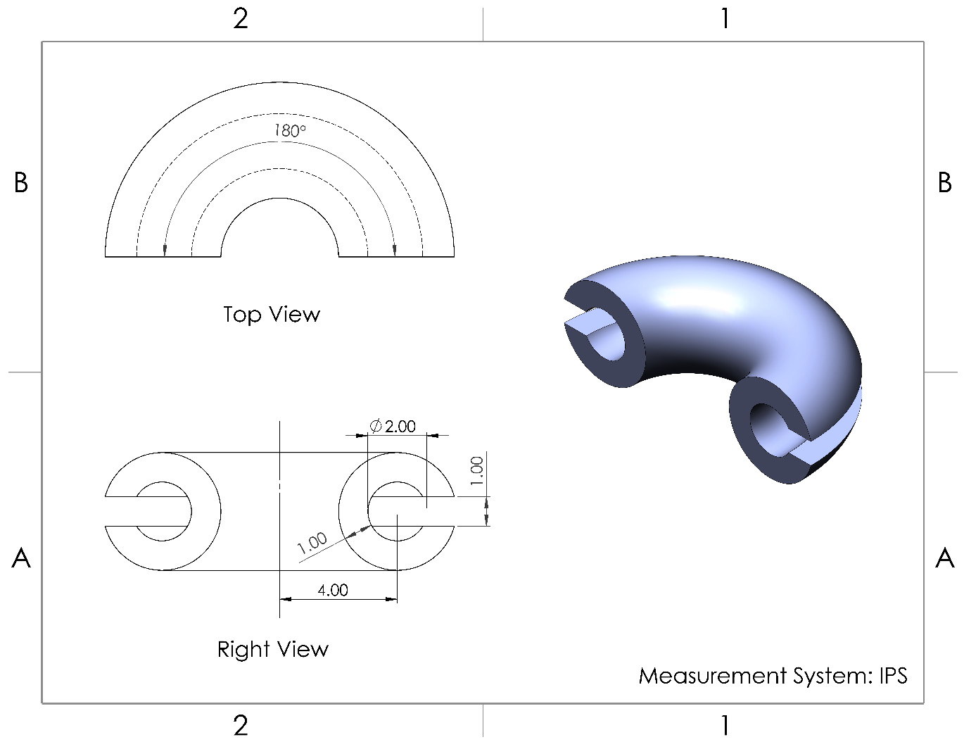
Figure 5.66 – The 3D model we are building using the revolved cut feature
Let's go ahead and complete the model:
- Planning: We'll use the model we created earlier and add the revolved extruded cut feature to create the desired final shape in the drawing.
- Sketching: Here, we will sketch and fully define a rectangle to make the new cut that's shown in the following figure. The height of the cut is shown in Right View as 1 inch and cuts through the thickness of the wall. You will notice that we picked 1.2 inches for the width of our rectangle since this will be enough to cut through the whole wall. There are more advanced ways to define the cut, but we won't be covering them here. The axis of revolution goes through the center of the model, which also goes through the origin that we provided in the previous exercise:
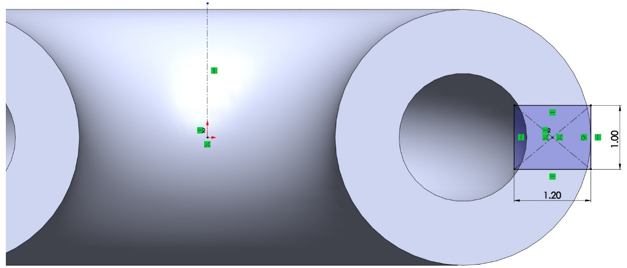
Figure 5.67 – The sketch used to apply the revolved cut feature
To apply the revolved cut feature, follow these steps:
- Select the Revolved Cut feature from the command bar, as follows:

Figure 5.68 – The location of the Revolved Cut feature
- Set up the PropertyManager options that are shown in the following screenshot. We are already familiar with these options. However, here, we're introducing a new end condition, Up To Surface. Now, select the other end of the surface, as shown in the following screenshot. After selecting the surface, we will see a preview of our revolved cut:
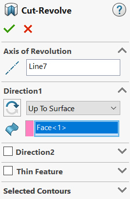
Figure 5.69 – The revolved cut PropertyManager
This end condition means that the cut will start from our sketch and end at a selected surface. Since our revolved cut goes through all of our shapes, it would be more convenient to end it by selecting the end surface rather than writing a numerical value for an angle. Another advantage of selecting this end condition is that it preserves our design intentions. For example, if we wanted to modify the angle of the revolved boss so that it's 270 degrees instead of 180, the revolved cut will update automatically and go through all of our shapes. However, if we use 180 degrees in a Blind end condition for our revolved cut and then update the revolved boss to 270 degrees, the cut will stay at 180 degrees:
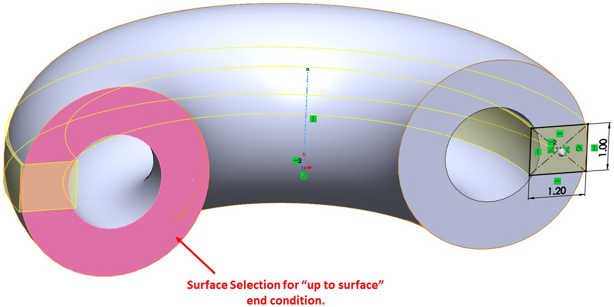
Figure 5.70 – The preview of the revolved cut feature
- Click on the green check mark to apply the cut. This will result in the following model:
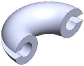
Figure 5.71 – The final 3D model after applying the revolved cut feature
This concludes how to apply the revolved cut feature. In this section, we discussed the following topics:
- How to apply the revolved cut feature
- How to use the Up To Surface end condition
Now that we've learned how to apply the revolved boss and revolved cut features, we will learn how to modify them.
Modifying revolved boss and revolved cut
The same procedure that we follow to modify the extruded boss and extruded cut features applies when we modify the revolved boss and revolved cut features. To recap, to edit or delete a revolved boss or revolved cut, we can right-click on the feature from the design tree and select Edit or Delete…, as required. The following screenshot highlights the Edit and Delete… commands that appear after right-clicking on a feature from the design tree:
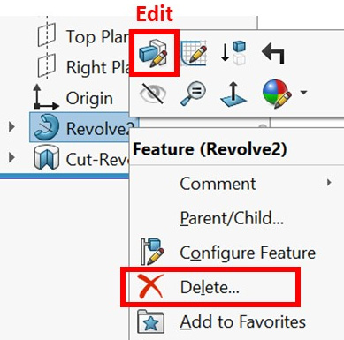
Figure 5.72 – The locations of the Edit and Delete… commands
This concludes this section on revolved boss and revolved cut. In this section, we learned how to apply these features, how to set them up, and how to modify them. Those two features will be important when we deal with rounded objects such as shafts and cylinders.
Summary
In this chapter, we have learned about our first set of SOLIDWORKS features, all of which allow us to go from creating 2D sketches to creating 3D models. Here, we learned about the extruded boss/extruded cut and revolved boss/revolved cut features. Each of these feature sets has an additive feature and a subtractive feature. We also learned about the fillet and chamfer features, which mainly aim to remove sharp edges for our 3D models. For each feature, we learned about what it was, how to apply it, and how to modify it.
In the next chapter, we will explore more features that are considered more advanced than the features we explored in this chapter. This includes swept boss/swept cut and lofted boss/lofted cut, both of which require more than a single sketch to be applied. We'll also address adding more reference geometries, such as new planes and coordinate systems.
Questions
Answer the following questions to test your knowledge of this chapter:
- What are the features in SOLIDWORKS?
- What are the extruded boss and extruded cut features?
- What are the fillet and chamfer features?
- What are the revolved boss and revolved cut features?
- Create the model shown in the following figure:

Figure 5.73 – The drawing for question 5
- Create the model shown in the following figure:

Figure 5.74 – The drawing for question 6
- Create the model shown in the following figure:
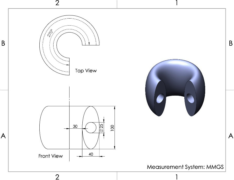
Figure 5.75 – The drawing for question 7
- Create the model shown in the following figure:

Figure 5.76 – The drawing for question 8
Important Note
The answers to the preceding questions can be found at the end of this book.