
Chapter 2: Interface and Navigation
In this chapter, we will look at SOLIDWORKS and its software interface, as well as its main components. In addition, we will cover how to navigate through the software interface so that you will be able to easily find your way around the software in the upcoming chapters. We will also talk about the document's measurement system in terms of the different standard units it uses globally, such as feet, inches, centimeters, and millimeters for measurements of length. Interacting and setting up an interface with the software and setting up our measurement system will be the first two actions we will perform in any new project.
The following topics will be covered in this chapter:
- Starting a new part, assembly, or drawing file
- Main components of the SOLIDWORKS interface
- The document's measurement system
Technical requirements
In this chapter, you will need to have access to SOLIDWORKS.
The project files for this chapter can be found in this book's GitHub repository: https://github.com/PacktPublishing/Learn-SOLIDWORKS-Second-Edition/tree/main/Chapter02.
Check out the following video to see the code in action: https://bit.ly/3EVROJv
Starting a new part, assembly, or drawing file
This section addresses the three types of SOLIDWORKS files: parts, assemblies, and drawings. Here, we'll briefly cover what each file is for and how we can use each of them; however, more about each type of file will be covered throughout this book.
What are parts, assemblies, and drawings?
As we just mentioned, SOLIDWORKS files fall into three distinctive categories: parts, assemblies, and drawings. Each file type corresponds to a certain deliverable when we're making a product. By deliverable, we mean whether we need to deliver a three-dimensional (3D) part file, a 3D assembly file, or a two-dimensional (2D) engineering drawing. To illustrate these three file types, let's break down the simple cylindrical box shown in the following diagram:

Figure 2.1 – A cylindrical box assembly consisting of two parts
We can induce three distinctive categories from the preceding cylindrical box diagram: parts, assemblies, and drawings. Let's take a look at each of these here:
- Parts: Parts are the smallest elements that make up an artifact. They are the first step in building any product in SOLIDWORKS. Since SOLIDWORKS is used to create 3D software, all of its parts are 3D. Also, each part can be assigned to one type of material. Our cylindrical box contains two parts: a main cylindrical container and a cap, as shown in the following diagram:

Figure 2.2 – Separating the parts comprising the cylindrical box assembly
After creating the two parts separately in two different part files, they can be put together into an assembly file.
- Assemblies: SOLIDWORKS assemblies are where you will be able to join more than one part together to make an assembly. Most of the artifacts we use in our everyday life contain more than one part, linked together. Some examples include cars, phones, water bottles, tables, and more. In our cylindrical box example, the assembly will look like this:

Figure 2.3 – A closed cylindrical box assembly
The main purpose of SOLIDWORKS assemblies is to check how different parts—which are often created separately—interact with each other. This will help us evaluate whether or not the parts fit together correctly. It also helps the design and engineering teams evaluate the look of the product as a whole. In addition, through SOLIDWORKS assemblies, we can simulate the movements of mechanical products.
- Drawings: SOLIDWORKS drawings allow you to create 2D engineering drawings out of your parts or assemblies. Engineering drawings are the most common way to communicate designs on paper. They often show dimensions, tolerances, materials, costs, parts identifiers (IDs), and so on. Engineering drawings are often required when designs need to be reviewed by certain parties. Also, they are often required if you wish to talk about your designs with clients or manufacturing/prototyping establishments. For our cylindrical box, an engineering drawing might look like this:
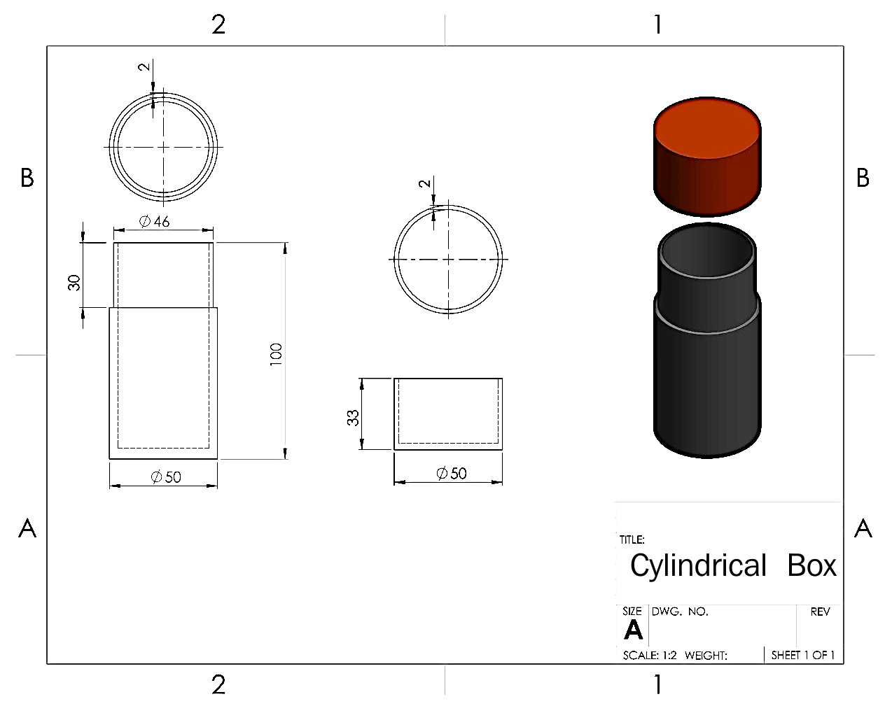
Figure 2.4 – A 2D engineering drawing communicating the design of the cylindrical box
All three types of files—parts, assemblies, and drawings—are essential to SOLIDWORKS users. This is because they are all necessary for the creation of products.
Now that we understand what parts, assemblies, and drawings are, let's look at how we can open them in SOLIDWORKS.
Opening a part, assembly, or drawing file
Now that we know the difference between parts, assemblies, and drawings, we will explore how to start each type of file. Once you open SOLIDWORKS 2022, a Welcome window will appear, along with some shortcuts. One of those options is starting a new Part, Assembly, or Drawing file. These options are highlighted in the following screenshot. Once you click on any of these options, that type of file will be opened:

Figure 2.5 – Default Welcome window once SOLIDWORKS is launched
If the Welcome message does not appear, there is another way to open a new file, as follows:
- Click on File in the top-left corner of SOLIDWORKS.
- Select New..., as shown in the following screenshot:

Figure 2.6 – Opening a new file in SOLIDWORKS
- After selecting New..., you will be able to pick one of the three options—that is, to either start a new Part, Assembly, or Drawing file, as shown in the following screenshot. You can select the type of file you want to work with and click OK. Alternatively, you can double-click on the file type you would like to start with.
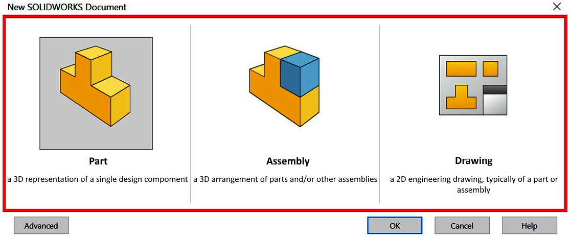
Figure 2.7 – The different options for a new SOLIDWORKS document
In this book, first, we will focus on creating parts, then assemblies, and—finally—drawings. Being able to distinguish between the different types of files is very important as everything we do afterward will be built on top of the file type we choose. Now that we understand how to open parts, assemblies, and drawings in SOLIDWORKS, let's look at how to use the software's interface further.
Main components of the SOLIDWORKS interface
In this section, we will discuss the main components of the SOLIDWORKS interface. These main components are the Command Bar, the Task Pane, the Canvas/Graphics Area, and the FeatureManager Design Tree.
Being familiar with these components is essential if we wish to use the software to a good extent. For a practical follow-up, you can download the SOLIDWORKS part linked with this chapter, which will be used to explain the main components of the SOLIDWORKS interface.
In this chapter, we will be focusing on the interface that's used when we need to deal with parts, instead of assemblies and drawings. However, the main components of the interface are the same when we deal with each file type.
When opening a part in SOLIDWORKS, regardless of whether it is new or existing, you will be faced with the view shown in the following screenshot. We will cover the four main categories of this screen: the Command Bar, the FeatureManager Design Tree, the Task Pane, and the Canvas/Graphics Area. These are the main sections of SOLIDWORKS that we'll be interacting with and referring to throughout this book.

Figure 2.8 – A breakdown of the SOLIDWORKS interface
We will look at the Command Bar, the FeatureManager Design Tree, the Canvas/Graphics Area, and the Task Pane in more detail in the following sections.
The Command Bar
The Command Bar is located at the top of the screen. It contains all the SOLIDWORKS commands that are used for building models. It contains different categories of commands, and each category contains a set of different commands. A close-up of the Command Bar is shown in the following screenshot:
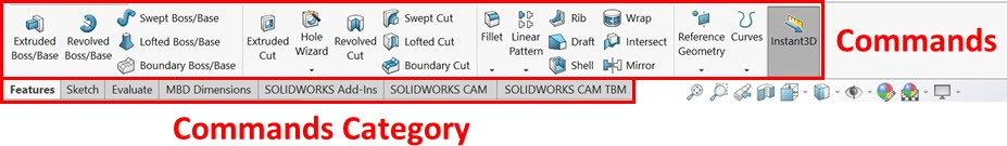
Figure 2.9 – A breakdown of the Command Bar
Different categories (tabs) of commands correspond to different functions. For example, in the Sketch category/tab, you will find all the commands that we will need in the sketching phase. In the Features category/tab, you will find all the commands that we will need in order to go from the sketching phase and start creating a 3D model. The categories that are shown in the preceding screenshot are not the only ones SOLIDWORKS provides, but they are the most common ones we will use. To show the hidden Commands categories, we can do the following:
- Right-click on any of the Commands categories, and then expand the Tabs menu. You will get the view shown in Figure 2.9, which contains more Commands categories, such as Surfaces, Weldments, and Mold Tools.
- Select the categories you want to be shown. By doing this, these categories will be added to the Command Bar, as illustrated in the following screenshot:
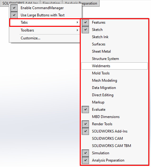
Figure 2.10 – List of command categories that can be added to the Command Bar
This concludes our overview of the Command Bar, which contains the different commands we will use as we build 3D models. Now, we will look at the FeatureManager Design Tree.
The Feature Manager Design Tree
The FeatureManager Design Tree details everything that goes into creating your parts. The following screenshot shows the FeatureManager Design Tree for the part we explored in this chapter. We can simplify the FeatureManager Design Tree by splitting it into four parts, as illustrated in the following screenshot:

Figure 2.11 – A breakdown of the FeatureManager Design Tree
The four parts of the FeatureManager Design Tree are listed here:
- Commands/Features: These are the commands that are used to build the model. This includes sketches, features, and any other supporting commands that were added during the modeling phase (since we are building a 3D model). In the preceding screenshot, two features were used to create the model, as indicated by Commands. The first is Boss-Extrude1 and the second is Cut-Extrude1. Note that these commands are listed in the order of when they were applied.
- Default Reference Geometries: The SOLIDWORKS canvas can be understood as endless space. These Default Reference Geometries are what can fix our model to a specific point or plane. Without these, our model will be floating in an endless space without any fixtures. Throughout this book, we will start our models from these default references. There are three planes (Front Plane, Right Plane, and Top Plane), in addition to the origin.
- Materials: Realistically, all of the artifacts we have around us are made of a certain material. Some examples of materials include plastic, iron, steel, and rubber. SOLIDWORKS allows us to assign which structural material the part will be made of. In the preceding screenshot, the Material feature is classed as <not specified>.
- Others: This section includes other aspects of our model's creation, such as History, Sensors, Annotations, and Solid Bodies. We will explore them later in this book.
Note
Through the book, we will use the term design tree as a shortcut to FeatureManager Design Tree.
The design tree helps us to easily identify how the model was built and in which sequence. This makes it easier for us to modify existing models. Now, let's look at the canvas.
The Canvas/Graphics Area
The canvas provides a visual representation of the model we have at hand. It contains three main components, as illustrated in the following screenshot:

Figure 2.12 – A breakdown of the Canvas/Graphics Area
Let's break down the components, as follows:
- Coordinate System: This shows the orientation of the model in relation to the default coordinate system in terms of the x, y, and z axes. They are interactive and can be used to position the viewing angle of the model. By clicking on the various axes, you can arrive at that viewing orientation.
- The part's current status: This shows the current status of the part at work. This is updated with every construction command that's used to build the model.
- Additional viewing commands: These provide alternative views of the model, such as the wireframe view and section view. It also provides shortcuts that we can use to modify the scene, the appearance of the model, and hide/show various properties.
When controlling the model in the canvas, using a mouse with a scroll wheel is recommended due to the functionalities the scroll wheel has. Here are two ways the scroll helps model control:
- When the cursor is within the canvas, rolling the scroll wheel will allow us to zoom in and out of the cursor's location.
- When the cursor is within the canvas, pressing on the scroll wheel and moving the mouse will rotate the model in a certain direction. For example, if we move the mouse to the right, the model will pivot to the right.
Note
We will use the term canvas throughout the book. However, many would use the term graphics area.
Now that we have covered the canvas, let's talk about the Task Pane.
The Task Pane
The Task Pane shows to the right of our interface by default. It contains shortcuts for the different tools we will be using in order to enhance the efficiency of our work. This includes access to common online resources and forums, as well as different tools, such as appearance adjustments and the View Palette (mainly for drawing files). In this book, however, we won't be using linked resources while making parts or assemblies. We will use the View Palette in Chapter 10, Basic SOLIDWORKS Drawing Layout and Annotations.
Now that we know about the major components of the SOLIDWORKS interface, we will learn how to adjust the measurement system of our open document.
The document's measurement system
Since SOLIDWORKS is an engineering software, all of the models are constructed in relation to user-provided (user-input) measurements. To facilitate communication, SOLIDWORKS uses standard systems that are currently used in the industry, including the International System of Units (SI), the imperial system, and variations of each.
Different measurement systems
When modeling with SOLIDWORKS, the user must take note of the measurement system that is set in the document. A measurement system is a set of common agreed-upon units that facilitate how we communicate quantities in terms of length, mass, volume, and so on. Some examples of such units are meters and inches, which are measurements of length.
These often correspond with internationally recognized systems such as the SI and the imperial system. The SI system is also commonly known as the metric system. Currently, it is used in most countries around the world. Another common system is the imperial system, which is mostly used in the United States (US).
The following table compares the major units that are used in the SI and imperial systems:
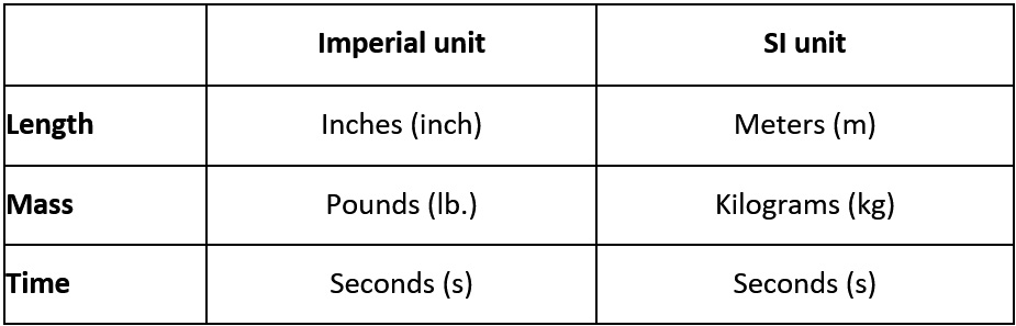
Figure 2.13 – A comparison between the imperial and SI unit systems
Before we start modeling anything in SOLIDWORKS, we must decide on which system to use. The unit system we use often depends on the standards that have been adopted by the organization we work for or by the requirements of our clients.
Adjusting the document's measurement system
Now that you have decided which system to use, you must set it up on the software. You can adjust the unit of measurement by following these steps:
- Open a new part file.
- In the bottom-right corner, you will find the current/default measurement system in an abbreviated form. Click on the displayed measurement system, as shown in the following screenshot:
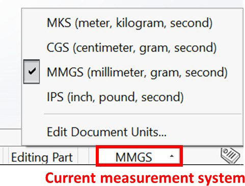
Figure 2.14 – The set and default options for unit systems
You can create your own measurement system by selecting Edit Document Units…. This will open the following window, where you can select custom options and customize and implement your own custom units:
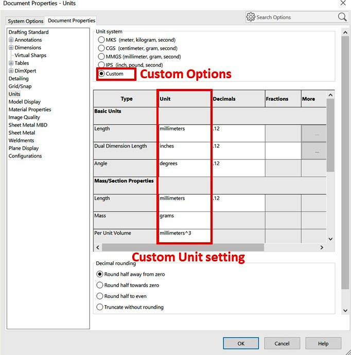
Figure 2.15 – Customizing the unit system
Note that you can change the set units at any time during the modeling process. This will convert all the units that were already set in the file. For example, let's assume that the document's length measurement was set to IPS (inch, pound, second) and a line was drawn to measure 2 inches. If we change the measurement system later to MMGS (millimeter, grams, second), the length of the line will be automatically converted into 50.8 millimeters. This is because 1 inch is equal to 25.4 millimeters.
Note
The same procedure on adjusting the measurement system applies to the part, assembly, and drawing file types.
Knowing how to deal with measurement systems is essential, as our design aim will be to produce a tangible object for production or prototyping. If we don't follow the required settings from the start, our final 3D model may not have a tangible value.
Summary
In this chapter, we learned how to start the different types of SOLIDWORKS files—that is, parts, assemblies, and drawings. We also learned about the main components of the SOLIDWORKS interface, as well as the different measurement systems that are available and how to adjust them. These are the first steps we need to follow when we plan to use the software to make a project and its foundations.
In the next chapter, we will start working with SOLIDWORKS sketching. Sketching is foundational to building any 3D model.
Questions
The following questions will help to emphasize the main points we have learned in this chapter:
- What are the three types of files a SOLIDWORKS user can create?
- What is the difference between SOLIDWORKS parts, assemblies, and drawings?
- What is contained in the canvas?
- What does the design tree show?
- What is the difference between SI units and imperial units?
- Open a new SOLIDWORKS part file.
- Set the unit for the new SOLIDWORKS file to MKS (meter, kilogram, second).
Important Note
The answers to the preceding questions can be found at the end of this book.