
Chapter 10: Basic SOLIDWORKS Drawing Layout and Annotations
It is important for designers and engineers to be able to explain their 3D models to other teams or manufacturers. This could be for the purpose of reviewing the design at hand or manufacturing it. In this chapter, we will learn how to use SOLIDWORKS' drawing tools to do that. We will cover how to generate simple drawings with orthogonal views, how to communicate dimensions and drawing information, and how to export drawings as shareable images or PDFs.
In this chapter, we will cover the following topics:
- Opening a SOLIDWORKS drawing file
- Generating orthographic and isometric views
- Communicating dimensions and design
- Utilizing the drawing sheet's information block
- Exporting the drawing as a PDF or image
By the end of this chapter, you will be able to generate simple engineering drawings to explain your design to individuals or groups that are not SOLIDWORKS users. You will also be able to produce drawings that can be used for manufacturing, documentation, and archiving.
Technical requirements
In this chapter, you will need to have access to the SOLIDWORKS software.
The project files for this chapter can be found at the following GitHub repository: https://github.com/PacktPublishing/Learn-SOLIDWORKS-Second-Edition/tree/main/Chapter10.
Check out the following video to see the code in action: https://bit.ly/3m3UOvQ
Opening a SOLIDWORKS drawing file
In practice, whenever we want to create a drawing in SOLIDWORKS, the first thing we will do is open up a new SOLIDWORKS drawing file. This will have a different format than parts and assemblies. In this section, we will learn how to open a drawing file. This will be our first step when we start working with SOLIDWORKS drawings. To open a new SOLIDWORKS drawing file, follow these steps:
- Click on New at the top of the interface, as shown in the following screenshot:

Figure 10.1 – The location of the button that allows you to open a new file
Tip
You can press Ctrl + N on the keyboard for a shortcut to open a new file.
- Select Drawing and click OK, or double-click on Drawing.
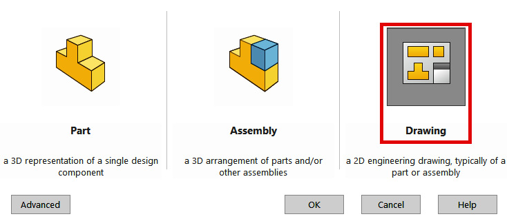
Figure 10.2 – We will work in a drawing document
- This will open up a drawing file, as shown in the following screenshot. The first window will prompt us to select the size of the drawing sheet we want to use. The list contains all the major standard sheet sizes that are used in the industry. In this exercise, we will select the first one, A (ANSI) Landscape, and then click OK:

Figure 10.3 – There are many standard sheets to pick from
This will open the following sheet and interface. We will be working with this throughout this chapter:
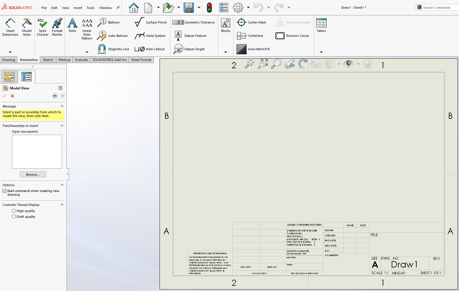
Figure 10.4 – The A (ANSI) Landscape sheet
In the rest of this chapter, we will work together to create a simple engineering drawing and export it as a PDF file so that it can be shared. In order to follow along, make sure that you download the SOLIDWORKS part file that comes with this chapter. The following figure shows the drawing we'll have by the end of this chapter:
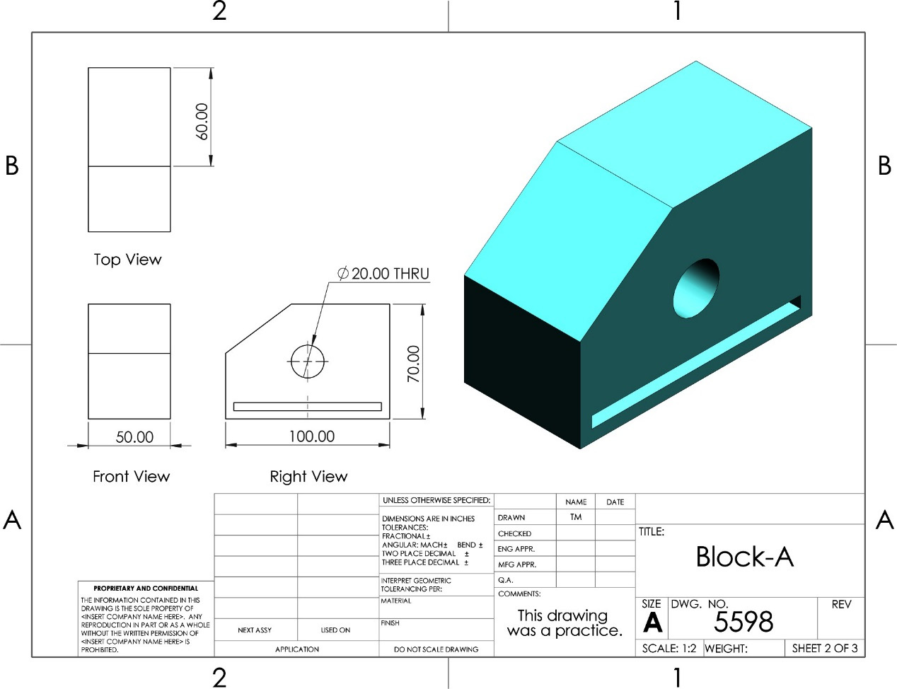
Figure 10.5 – The final drawing we will produce in this chapter
Now that we know how to open a SOLIDWORKS file, we need to generate the standard orthographic views and isometric projection for our model.
Exploring and Generating orthographic and isometric views
The drawing views that we will use the most for our drawings are orthographic and isometric. These views are the simplest to interpret. In this section, we will create a drawing file and input orthographic and isometric views into it. We will also cover the scales and display styles for our drawing. We will start by selecting our targeted model. Then, we will create and adjust the views so that we can coordinate our ideas.
Selecting a model to plot
SOLIDWORKS' drawing tools are based on parts or assemblies that have already been modeled. A drawing file will be linked to the parts or assemblies it communicates with. Thus, after opening a drawing file, our first step is to select the part or assembly file that we want to include in the drawing. Throughout this practical exercise, we will use the following model to create the drawing. To follow along, download the model that's linked to this chapter:

Figure 10.6 – The 3D model we will generate a drawing for
To start drawing, follow these steps:
- Open a new drawing file. We covered this process in the previous section.
- After opening a new drawing file, you will notice that the Model View selection will be shown on the left, as highlighted in Figure 10.7. If not, we can select it by clicking on Model View in the Drawing tab.
- Click on Browse... to find the model you want to use.

Figure 10.7 – The Model View button to insert a 3D model
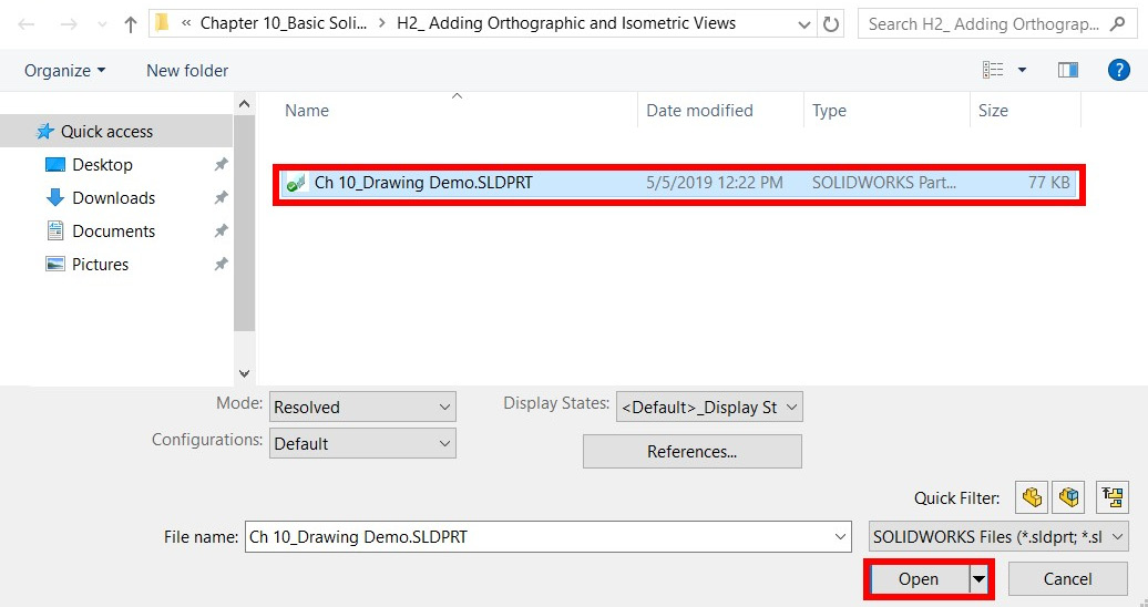
Figure 10.8 – The 2D drawing is generated from a 3D model
This will open a link between our part and our drawing file. Next, we will generate our orthographic and isometric views.
Generating orthographic and isometric views
Once we've selected the model from the model view, we can automatically input our orthographic and isometric views. Note that orthographic views are third-angle projections. After generating the third-angle orthographic projections, we will cover how to change them into first-angle projections. To generate the orthographic views, we can follow these steps:
- Move the cursor onto the body of the sheet. A rectangular outline will appear. By default, this indicates the front view of the model. This is shown in the following screenshot:

Figure 10.9 – The front view will appear when dragging a part into the drawing
- Left-click the mouse to input the front view. After that, move the mouse to the right of the view. You will see the right view appear, as shown in Figure 10.10. Left-click the mouse again to input that view.
- Then, move the mouse to the top of the front view to see the top view. Left-click again to input that. Then, move the mouse to the upper-right side of the front view. You will see the isometric view appear. Left-click again to input that view:
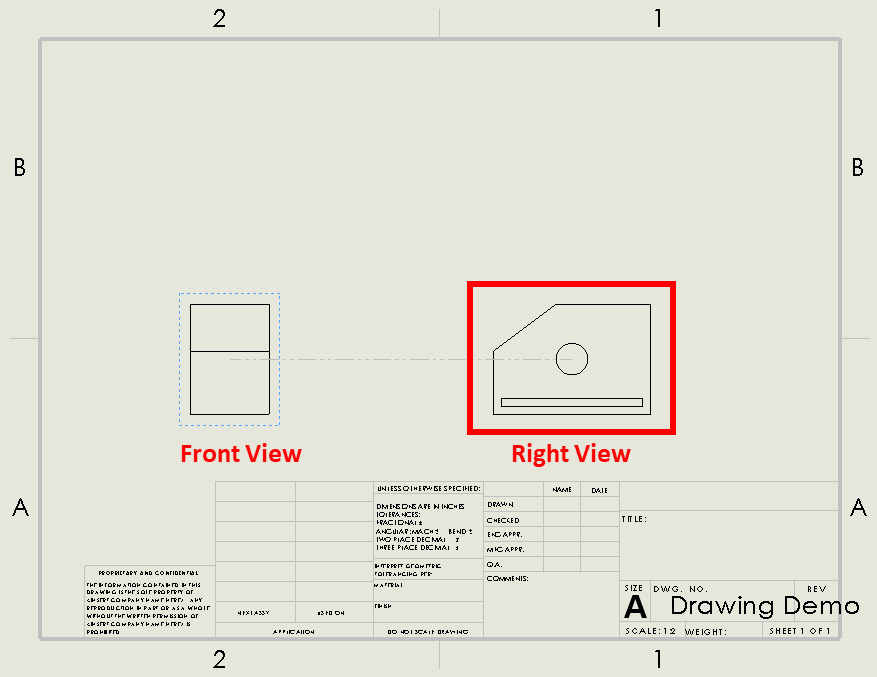
Figure 10.10 – The orthographic views are generated dynamically
Note
This is a dynamic way of inputting orthographic and isometric views. If we move the mouse in any direction, we will notice that the view changes. These additional views are referred to as projected views.
- After inputting the front, right, top, and isometric views, we can simply press Esc on the keyboard or click on the green checkmark at the top right to confirm that the views are correct, as shown in the following screenshot:
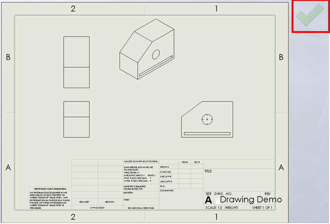
Figure 10.11 – After inserting the views, we can click the indicated checkmark to confirm them
At this point, we should have a few orthographic views, as well as an isometric view, in our drawing canvas. Before we make further adjustments to our drawing views, we need to address how to change our orthographic projections from third-angle to first-angle and vice versa. In addition, we will address some principles that are related to our initial views, that is, parent and child views, another way we can insert views, and how to delete views. We will start by learning about parent and child views.
Changing from third-angle to first-angle projections
The orthographic projections made earlier in this exercise were third-angle projections. However, you might be requested to produce drawings in first-angle projections. If that is the case, we can simply change the projection style to match the requirements. To adjust the projection style, follow these steps:
- Right-click on the drawing sheet from the drawing tree and select Properties…, as shown in the following screenshot:

Figure 10.12 – The sheet properties can be found in the drawing design tree
- Under the Sheet Properties tab, there is an option for the type of projection, as shown in the following screenshot. You can select the required type, then click Apply Changes:

Figure 10.13 – The sheet properties allow you to adjust an active sheet
Once the changes are applied, the existing views will switch from being third-angle projections to first-angle projections. The same procedure can be followed to change the projection type from a first angle to a third angle. Now, we can move on to exploring other drawing principles, starting with the parent and child views.
Parent and child views
Note that in the preceding drawing, the right, top, and isometric views were created based on the front view. As such, we can understand the front view as the parent view of all the other views that it inspired in terms of their creation. The following figure highlights the parent view and child view of the drawings we just created. This allows us to propagate changes to more than one view at a time. When we move the parent view, we will see that all the child orthographic views move with it. Also, when changing aspects, such as the drawing scale in the parent view, they will be copied to all the child views:
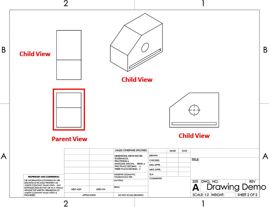
Figure 10.14 – Parent and child views
By default, child views will copy the features of the parent view. However, we can stop this from the drawing view's property manager. Next, we will explore another way of adding views: by using the View Palette.
Adding views via the View Palette
Other than adding views via the model view feature, we can add separate views more flexibly via the View Palette. We can access the View Palette via the Task Pane on the right-hand side of the screen. If the Task Pane is not visible, you can display it by clicking on View | User Interface | Task Pane, as shown in the following screenshot:

Figure 10.15 – The Task Pane has to be shown in the user interface to use it
Now that we have the Task Pane visible, we can use it to insert views via the View Palette. To do it, we can follow those steps:
- Click on the View Palette from the shortcuts menu on the right-hand side of the screen, as shown in the following screenshot:
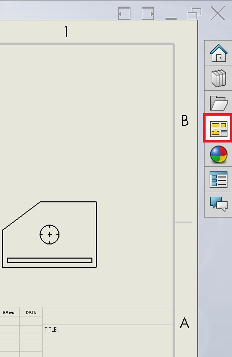
Figure 10.16 – The location of the View Palette
- If the model is already selected, we will be able to see it in the drop-down menu at the top of the options, as highlighted in the following screenshot. If not, we can browse to select a part or assembly:
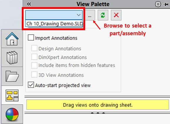
Figure 10.17 – A drop-down menu showing the active 3D model in the drawing
- Once we've selected the model, we will have a number of viewing options to choose from, as highlighted in the following screenshot. To add a view, we can simply drag it onto the drawing sheet:

Figure 10.18 – Different views that can be directly dragged onto the drawing sheet
- Drag the Trimetric view from the View Palette onto the drawing canvas. This will insert that view into the drawing, resulting in a drawing as in the following figure:
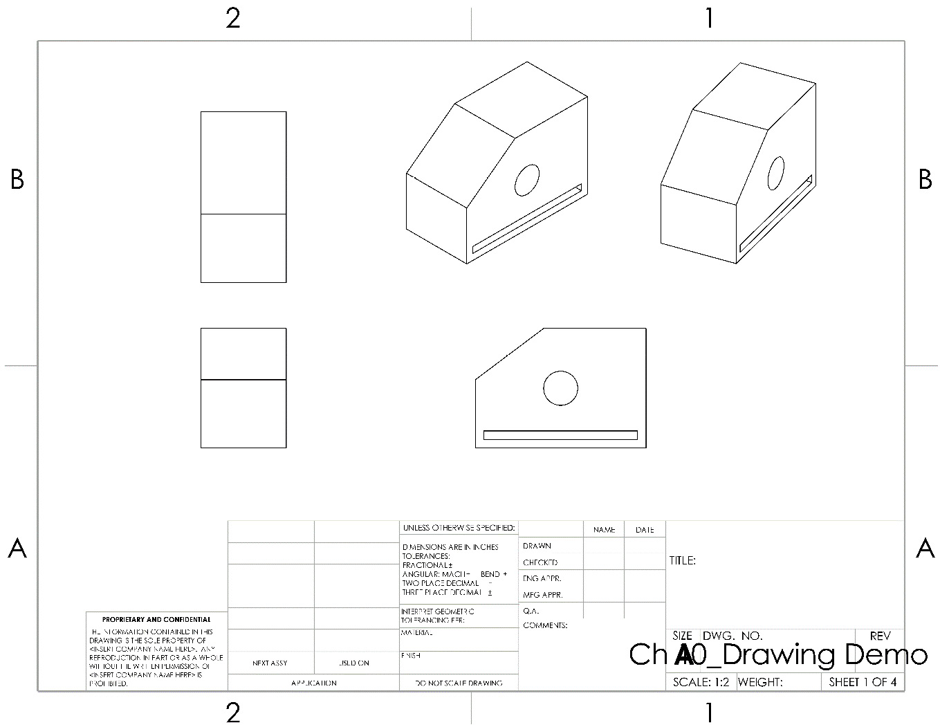
Figure 10.19 – The resulting drawing with an additional trimetric view
Using the View Palette to add views provides us with a quicker way to directly drag and drop specific drawing views from the side of the interface. The current view represents the last part of the orientation in the original .SLDPRT file. Next, we will learn how to delete views.
Deleting views
Often, we may input a drawing view and decide to delete it later. For example, after inserting the trimetric view, which we did earlier, we came to the conclusion that it adds no value; thus, we would like to delete it. There are two methods we can follow when it comes to deleting a drawing view:
- Method 1: Select the drawing view on the drawing sheet and then press the Delete key on the keyboard. We will get a Confirm Delete message, as shown in the following screenshot. To delete the view, click Yes:

Figure 10.20 – A confirmation message appears when deleting a view

Figure 10.21 – We can delete a view using the Delete option
This concludes the two common methods we can follow to delete a certain view from our drawing's canvas.
In this section, we have added orthographic and isometric views to our drawing file. However, note that we still have lots of empty space in our drawing sheet, which means we can make our drawing views larger. We will address the drawing scale and display in the next section.
Adjusting the drawing scale and the display
With SOLIDWORKS drawings, we also have the option of adjusting the size of our displayed view and what it looks like. In this part, we will continue working on our drawing by adjusting both the size and the display style.
Adjusting the scale of our drawing
When we input the drawing views into the drawing sheet, SOLIDWORKS automatically sets a certain suitable scale for our drawing. The scale refers to the size of the drawing as it's displayed in the drawing sheet. Regardless of the drawing that's displayed, we can change it. To highlight how we can change the drawing scale, we will adjust the scale for the front view (a parent view) and the isometric view (a child view).
Changing the drawing scale for the front parent view
To change the drawing scale for the front parent view for our drawing, follow these steps:
- Click on the front (parent) view.
- In the PropertyManager, scroll down to find the scale listing. When clicking on the drop-down menu, we will see multiple options for drawing scales. We can also select User Defined if we wish to define our own scale:
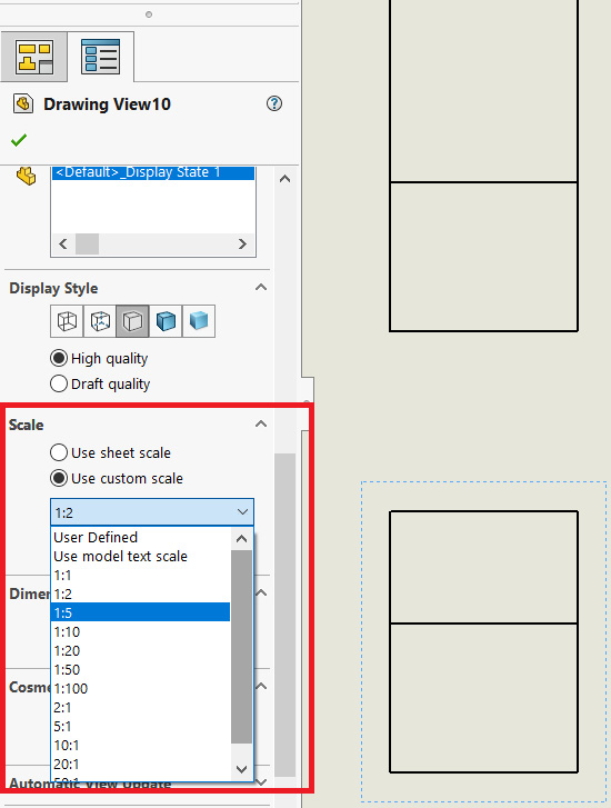
Figure 10.22 – Adjusting the scale using the PropertyManager
- Set the scale to 1:5. We will notice that all the drawing views become smaller, as shown in the following figure. Note that all the views changed in scale as well. This is because they are linked to the parent view by default:
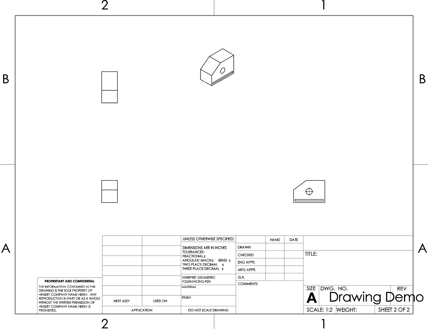
Figure 10.23 – The scale of the child views will change with the parent view
Note
After changing to the new scale, the views are very small in relation to the drawing sheet. It would be better if we were to enlarge the scale more.
Note that there is no right or wrong scale. The best way to find the best scale is to try different ones until you are satisfied with the size and proportion of your drawing views. Now that we've looked at the parent view, we will learn about changing the scale of a child view.
Changing the drawing scale of the isometric child view
To change the drawing scale of the isometric child view, we can follow the same steps that we followed for the front view. However, there is one slight difference. Follow these steps to change the scale:
- Select the isometric view and find the scale menu in the PropertyManager. Note that the scale is set to Use parent scale. This is why the scale of the isometric view changed as well when we changed the scale of the front view. To change the scale, select Use custom scale. Then, adjust the scale to 1:1:
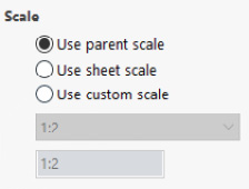
Figure 10.24 – We can set a different scale for a child view compared to the parent
- As we can see, the front view became much bigger, while all the other views remained the same size. The resulting drawing will look as follows:
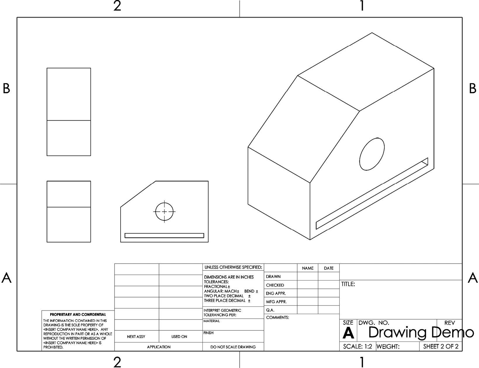
Figure 10.25 – The drawing after adjusting the scales
Tip
You can move the views around by clicking and holding the left mouse button. We usually do this to arrange our views.
Now, we have the final scale for our drawing set. However, before we move on to adjusting the display, let's talk about the scale ratios that are provided within SOLIDWORKS.
Understanding scale ratios
In the drawing we created earlier, we had two scales: 1:2 and 1:1. Let's take a look at what the first and second numbers refer to:
- First number: The first number refers to the actual object size from modeling. In other words, it refers to the dimensions we used when we made the part in the first place.
- Second number: The second number refers to the size on the drawing sheet. This relates to the final printing size of the drawing paper. Remember that when we first started our drawing file, we had to select a drawing sheet standard, which included the size of the drawing paper.
Now, let's put these two numbers together. If we were to manufacture the actual object and print the drawing sheet for our model, we would notice the following:
- The drawing sizes of the front, side, and top views are half the size of the actual object; thus, the scale is 1:2.
- The drawing size of the isometric view is exactly the same size as the actual object; thus, the scale is 1:1.
Now that we understand the scaling ratio and how to adjust our scales, we can start learning about the different displays and how to adjust them.
Different display types
Apart from the drawing view scale, we can also adjust how the drawing is displayed. There are five different displays we can use with our drawing views. These are highlighted in the following table and relate to the isometric view we have in our previous drawing:
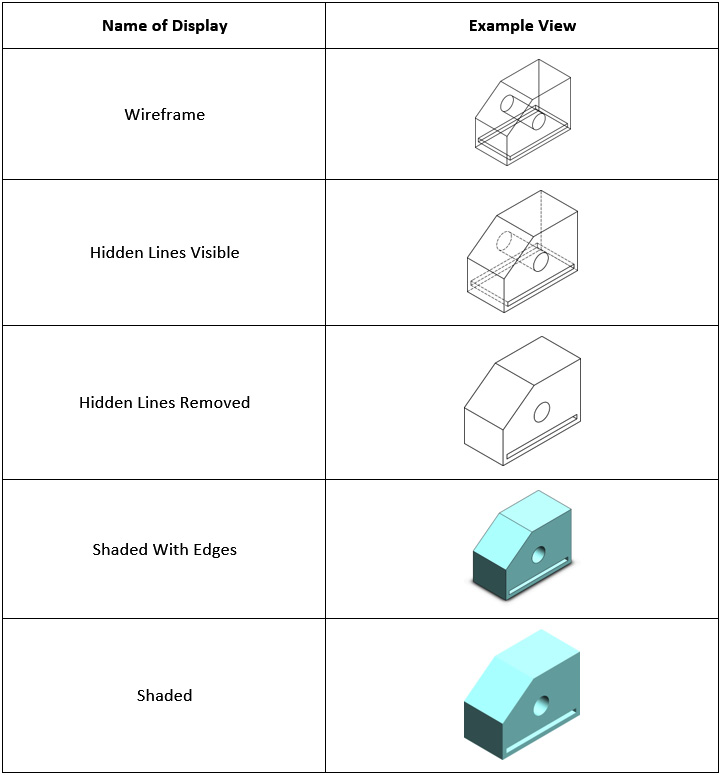
Figure 10.26 – The different display types we can use with the drawing views
To change the display of our isometric view to one of the ones shown in the preceding table, follow these steps:
- Select the isometric view in the drawing sheet.
- From the PropertyManager, find Display Style, as shown in the following screenshot. The small icons that are circled indicate the different display styles that were shown in the preceding table. Note the Use parent style option here, too—we can leave that checked if we want it to match the parent display style. Selecting any of the other view styles will automatically uncheck that box:

Figure 10.27 – The location of the Display Style option in the PropertyManager
- Change the display to Shaded With Edges, which is the fourth icon from the left. After this, our drawing will look as follows:

Figure 10.28 – Our drawing after changing the display style
Similar to drawing scales, there is no right or wrong view. It all depends on us as designers and draftsmen. We have to make the best decision when it comes to which view communicates our message the best.
So far, we have our drawing views, along with our desired display style, in our drawing canvas. These are used to communicate the shape of the model. Next, we will learn how to communicate dimensions in the drawing sheet.
Communicating dimensions and design
Now that we have different views in our drawing sheet, we can start adding information so that we can communicate the different elements of our drawing. In this section, we will cover how to add dimensions to our views and how to add different annotations, such as centerline and hole callout, to communicate our drawing in a clearer way. Having dimensions in our drawings is often necessary since we are often designing physical products. Dimensions help us communicate the size of our objects. Other annotations, such as centerline, notes, and hole callout, help us communicate the specifications of holes, centers of circles, and general notes we want to convey to whoever is viewing our drawing. We will start by learning how to display numerical dimensions using the Smart Dimension tool.
Using the Smart Dimension tool
The Smart Dimension tool allows us to easily display dimensions in our drawings. We will continue working with our previous drawing and add the selected dimensions to our drawing sheet. We will add the dimensions that are highlighted in the following drawing:

Figure 10.29 – Our end drawing after adding the dimensions
To add dimensions, follow these steps:
- Under the Annotation tab, select the Smart Dimension option, as highlighted in the following screenshot:

Figure 10.30 – The Smart Dimension option
- Now, we can simply click on whatever part of the drawing we like to dimension it. This works very similarly to the Smart Dimension feature we used in sketching.
- Click on the lines arrowed in the following figure to add dimensions to them. The first click will show the dimension, while the other click will confirm it:
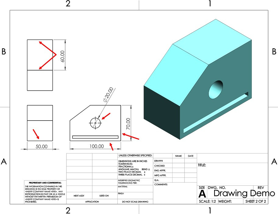
Figure 10.31 – Click areas to display the shown dimensions
This concludes how we can use the Smart Dimension tool in drawings. In addition to dimensioning line lengths and circle diameters, we can also dimension angles or any distance between two selected points.
Note
Using the Smart Dimension tool within drawings doesn't change the dimensions of the model. By default, it will display the dimension set in the 3D model itself.
If we mistakenly input a dimension we don't want, we can delete it. To delete a dimension, we can do one of two things:
- Right-click on the dimension and select Delete.
- Select the dimension and press the Delete key on the keyboard.
Now that we have our drawing views dimensioned, we can start inputting additional annotations to make it easier for others and ourselves to understand the drawing. In the next section, we will input centerlines, notes, and the hole callout.
Centerlines, center marks, notes, and hole callout annotations
In addition to dimensions, we can further clarify our drawings by adding additional annotations, such as centerlines and notes. SOLIDWORKS drawings provide an array of annotations we can use. However, we will only be covering the following in this section:
Centerlines
As the name suggests, centerlines highlight the center of drawing entities. They can highlight the center between two lines. In the drawing we created earlier, we will add the following centerline, which is highlighted in the right-hand view:
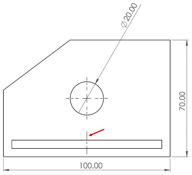
Figure 10.32 – The centerline we will add in the exercise
To add a centerline, follow these steps:
- Under the Annotation tab, select Centerline, as shown in the following screenshot:
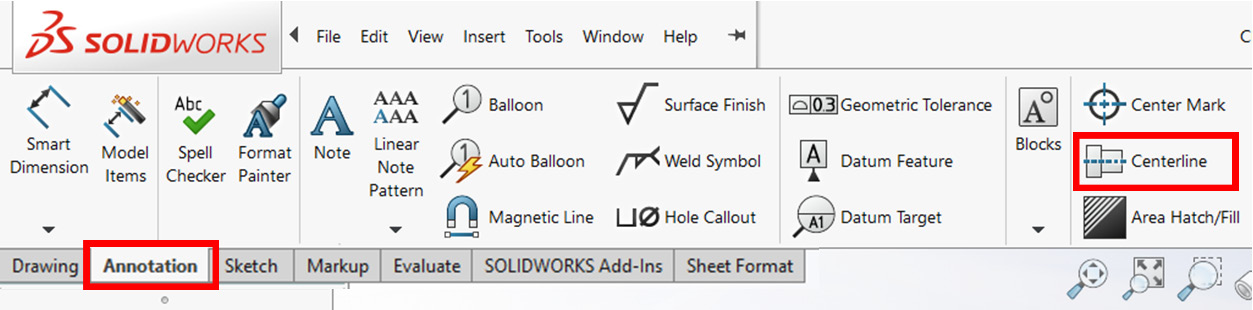
Figure 10.33 – The location of the Centerline option
- Now, we can click on the two entities we would like to create a centerline between. In our drawing, click on the two lines shown in the following screenshot. This will automatically put the centerline between them:

Figure 10.34 – Click areas to add the required centerline
This concludes how we can generate a centerline in SOLIDWORKS drawings. Centerlines can make it easier to interpret parts and design intents from drawings by indicting a central location between any two lines in the drawing.
Tip
We can extend the centerline as needed by dragging one end of it in a certain direction.
Next, we will address center marks.
Center marks
Center marks mark the center of circles, fillets, and slots to make them easier to identify when evaluating a drawing. The following figure indicates a center mark of a circle:
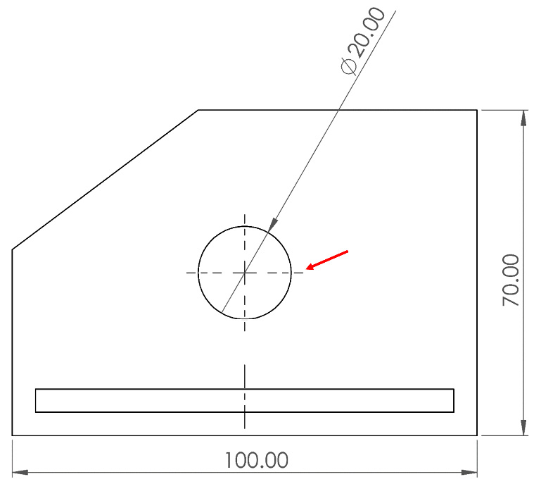
Figure 10.35 – A center mark indicating the center of a circle
To add a center mark, follow these steps:
- Under the Annotation tab, select Center Mark, as shown in the following screenshot:
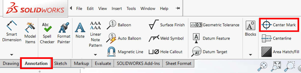
Figure 10.36 – The location of the Center Mark option
- Now, we can directly click on circles, fillets, and slots to insert a center mark.
The Center Mark PropertyManager also has the option to auto-insert a center mark in our drawing views. This can save us time if we intend to add center marks to all circles, fillets, and slots. The Auto Insert option is highlighted in the Center Mark PropertyManager in the following screenshot:

Figure 10.37 – The Auto Insert option inserts center marks automatically to applicable entities
Tip
You can have SOLIDWORKS insert center marks automatically with holes, fillets, and slots as you are inserting the drawing views. To enable this, you can go to Tool | Options | Document Properties | Detailing. Then, under the Auto insert on view creation title, you can check the options for center marks. This can save you time and effort if you are inserting center marks all the time.
Next, we will learn how to add notes to our drawings.
Notes
Notes are text indications that we can add to our drawings to highlight any specific aspect of it. We can understand it as an open text box for us to write anything that we are trying to convey. To highlight how can we use notes, we will add the indicated notes to the following drawing.
To add a note, follow these steps:
- Under the Annotation tab, select the Note option, as highlighted in the following screenshot:

Figure 10.38 – The location of the Note option
- Move the cursor to the drawing sheet and click under the front view. This will open a text box. Write Front View into it. Take note of the text format popup, as shown in the following screenshot. This allows us to easily adjust the format of the note, including its size, color, and font:

Figure 10.39 – The text format shortcut allows us to easily modify our note's format
- Input the Right View and Top View notes in the same way.
Tip
While inputting a note, if we move the cursor toward lines in the drawing, SOLIDWORKS will automatically generate an arrow pointing toward that location for the note.
This concludes how can we add notes to our drawing. Next, we will learn how to use the hole callout command with holes.
Hole callout
The hole callout feature allows us to easily present information related to a particular hole in our model. This information includes the diameters of the hole, the length of the hole, and any standards related to the creation of the hole. To demonstrate this feature, we will use it on the hole shown in the right-hand view of our drawing. Note that the following figure also highlights the difference between the normal Smart Dimension we used earlier and the Hole Callout feature:

Figure 10.40 – The outcome from the Smart Dimension versus the Hole Callout commands
To add a hole callout, follow these steps:
- Under the Annotation tab, select Hole Callout, as highlighted in the following screenshot:
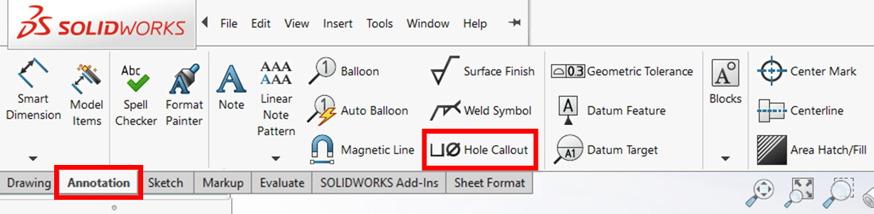
Figure 10.41 – The location of the Hole Callout option
- Click on the circular hole we want to call out. In this case, it is the circle indicated in the right-hand view, as shown in the following figure. Once we click on the hole, the hole callout will appear, along with all the information linked to that particular hole:
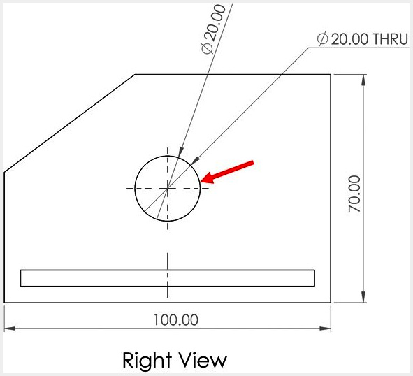
Figure 10.42 – The click area to get the hole callout
- Delete the smart dimension input to make the drawing look cleaner.
Note that in this example, the information that's linked to the hole is its depth, marked as THRU, which indicates that the hole goes through all the models. If the hole has more information linked to it, such as a different hole type, it will be displayed within the callout as well, as shown in the following drawing:
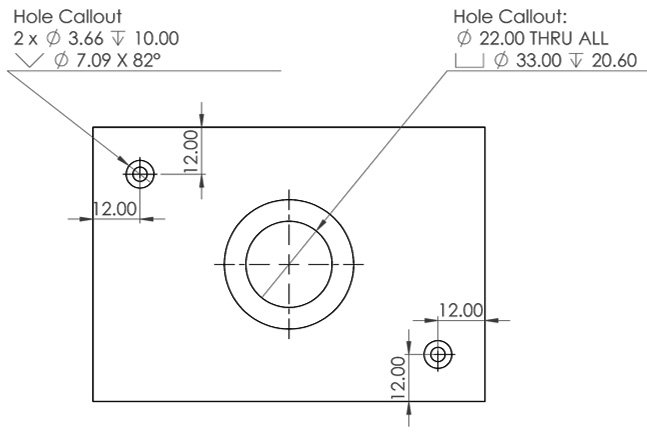
Figure 10.43 – Different types of hole callouts
This concludes how we can use a hole callout. At this point, our drawing has all the required views, display types, dimensions, and annotations. Next, we will learn how to adjust the information block, which contains information that's relevant to us, such as its name, number, company, and designer.
Utilizing the drawing sheet's information block
In this section, we will cover how to edit the information block that's located at the bottom of our drawing sheet. This information block displays information such as material, mass, drawer, reviewer, and drawing number. The information block in our current drawing is highlighted with a red box in the following screenshot. We will cover how to edit the existing information and how to add new information to the block:
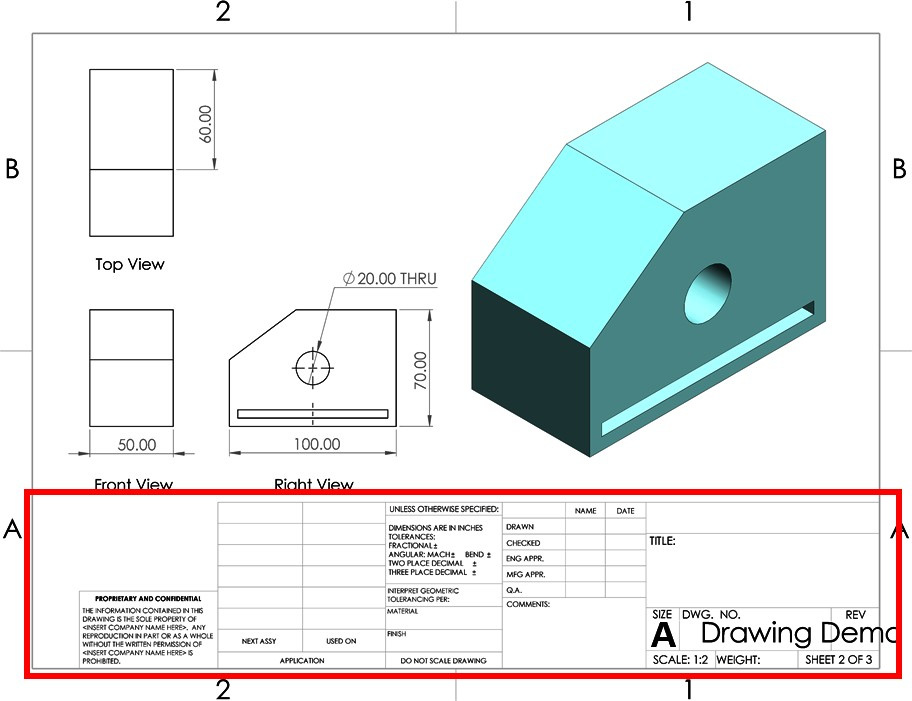
Figure 10.44 – The information block shows information related to the drawing
Now that we know what an information block is, we can start adjusting it.
Editing the information block
In this exercise, we will make the following edits:
- TITLE: Block-A
- DWG. NO.: 5598
- DRAWN NAME: TM
To edit the information in the sheet, follow these steps:
- Right-click anywhere in the drawing sheet. Then, select Edit Sheet Format, as shown in the following screenshot. Make sure that you don't right-click the drawing view:

Figure 10.45 – The menu showing the Edit Sheet Format option
- Now, the drawing lines surrounding the information block will turn blue, as shown in the following screenshot. This means we can edit the information block. The boxes for TITLE, DWG. NO., and DRAWN NAME already have text boxes. All of them are empty except for DWG. NO., which will take the name of the file by default. However, the empty fields already have text boxes that we can fill out. We can see these boxes by clicking in the middle of the empty box. The text box for TITLE is highlighted in Figure 10.46 as well. To edit the TITLE box, we can double-click on it and input the text we want. Edit the text so that it displays the following information:
- TITLE: Block-A
- DWG. NO.: 5598
- DRAWN NAME: TM
The output is shown in the following screenshot:
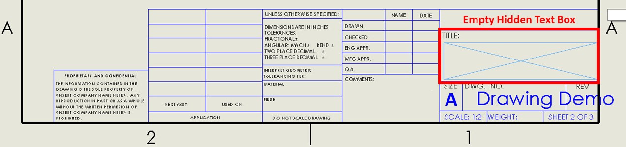
Figure 10.46 – Double-clicking on the empty boxes enables you to modify them
- Exit the information block's edit mode by clicking on the icon highlighted in the following screenshot. This is located on the top right-hand side of the drawing canvas:

Figure 10.47 – Exit the editing mode by clicking on the indicated icon
Tip
When in editing mode, we can modify the location of a text box by dragging it.
This concludes how we can edit information in our drawing information block. However, we've only learned how to edit existing information. Next, we will learn how to add new information boxes to the information block.
Adding new information to the information block
In addition to editing information and filling in existing text boxes, we can also add new text boxes to our information block. In this exercise, we will add the following text under COMMENTS: This drawing was a practice.. To do this, follow these steps:
- Right-click the drawing sheet and select Edit Sheet Format to start editing the information sheet.
- Note that the note field doesn't have an existing text box. To add text, we need to add a normal note. We can do this by selecting the Annotation tab and then selecting Note, as highlighted in the following screenshot. Then, we can insert the note under the COMMENTS heading in the information sheet:
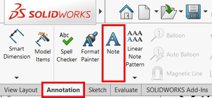
Figure 10.48 – The location of the Note option
- After inserting the note, we can type in the text This drawing was a practice., as shown in the following screenshot:
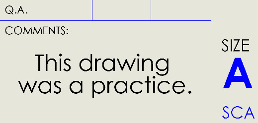
Figure 10.49 – The note typed in the comments section
- Exit the sheet format editing mode. The final drawing will look as follows:
Figure 10.50 – The final look of our drawing
This concludes how to add additional text to our drawing information block. At this point, our drawing is complete for the purpose of this exercise. You can always add more edits and information to the information block to meet your requirements.
To share the drawing with other individuals, especially if they don't have access to SOLIDWORKS, we will need to export the drawing as an image or PDF so that they can view it. We will learn how to do this next.
Exporting the drawing as a PDF or image
Now that we've completed creating a drawing with SOLIDWORKS' drawing tools, we need to export it as a PDF or image file so that we can share it with individuals who don't have access to SOLIDWORKS. This is what we'll do in this section. First, we will export the drawing as a PDF file, and then as an image.
Exporting a drawing as a PDF file
To export a drawing as a PDF file, follow these steps:
- Click on the Save As option, as shown in the following screenshot:
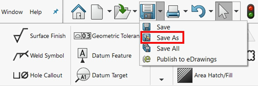
Figure 10.51 – The Save As option
- Under Save as type, open the drop-down menu and select Adobe Portable Document Format (*.pdf), as highlighted in the following screenshot:
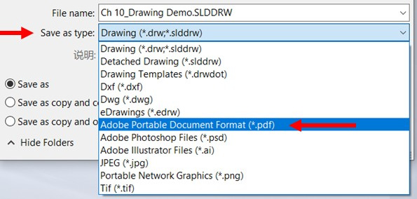
Figure 10.52 – Saving the drawing as a PDF document
This concludes how to save the drawing sheet as a PDF file. Next, we will learn how to export it as an image.
Exporting the drawing as an image
Exporting the drawing as an image is similar to exporting the drawing as a PDF. Follow these steps to do so:
- Click on the Save As option.
- Under Save as type, open the drop-down menu and select Portable Network Graphics (*.png), as highlighted in the following screenshot. We can also select other image formats if needed:

Figure 10.53 – Saving the drawing as a PNG image
- Click on Options..., as shown in the following screenshot:
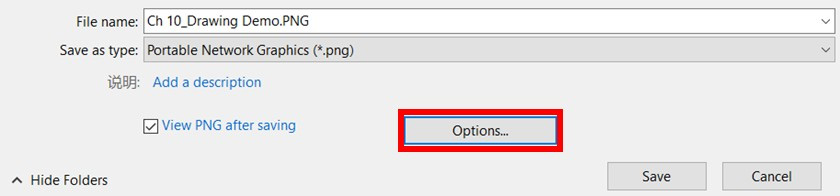
Figure 10.54 – The Options menu allows you to set the quality of the saved image
- Double-click on the options that are highlighted in the following screenshot. Click OK after fixing these options. The marked options indicate the following:
- Print capture: This exports the image as a print. When exporting the image for sharing, it is best to use the Print capture option. The Screen capture option prints whatever is shown on your drawing canvas.
- DPI: This stands for dots per inch. The higher the number, the better the quality of our exported drawing print.
- Paper size: This allows you to determine the paper print size of the export:
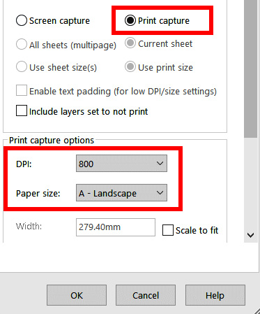
Figure 10.55 – The settings used in this exercise
- Click on OK and then Save to save and export the image. This will save the file as a PNG in the designated folder.
This concludes how to save the drawing sheet as an image. We can now share our drawings with others as an image or a PDF. These formats can be accessed by larger groups of people without them needing access to special software such as SOLIDWORKS.
Note that, throughout this chapter, we have focused on generating a drawing to communicate a SOLIDWORKS part. However, the same principles apply when communicating an assembly.
Summary
Engineering drawings are what engineers and designers use to communicate their designs to other parties, such as manufacturers. SOLIDWORKS provides us with comprehensive tools that we can use to generate those drawings. In this chapter, we learned how to input the most basic drawing views, that is, orthographic and isometric views. Then, we learned how to adjust the drawing scale and display style for a particular view. After that, we learned how to add dimensions and different annotations, such as centerlines and hole callouts. Finally, we learned how to adjust the information block and export the drawing as an image or PDF file.
The skills we learned about in this chapter allow us to communicate our designs to external entities. Drawings present the link between us as SOLIDWORKS users and others who don't have access to or expertise in the software. This is what makes the topics in this chapter important.
In the next chapter, we will discuss how to add a Bill of Materials (BOM) to our drawings to highlight the different parts that are used in an assembly.
Questions
Answer the following questions to test your knowledge of this chapter:
- How can we open a new drawing file?
- What different display styles can we use with our drawing views?
- What is the best scale to use for our drawing views?
- What is the information block we can often find at the bottom of a standard drawing sheet?
- Download the model linked to this chapter and duplicate the shown drawing (sheet specs: A (ANSI) Landscape, scale 1:3). The measurements system has been set to MMGS:

Figure 10.56 – The drawing for question 5
- Download the model linked to this exercise and duplicate the shown drawing (sheet specs: A4 (ANSI) Landscape, scale 1:3). The measurements system has been set to MMGS:
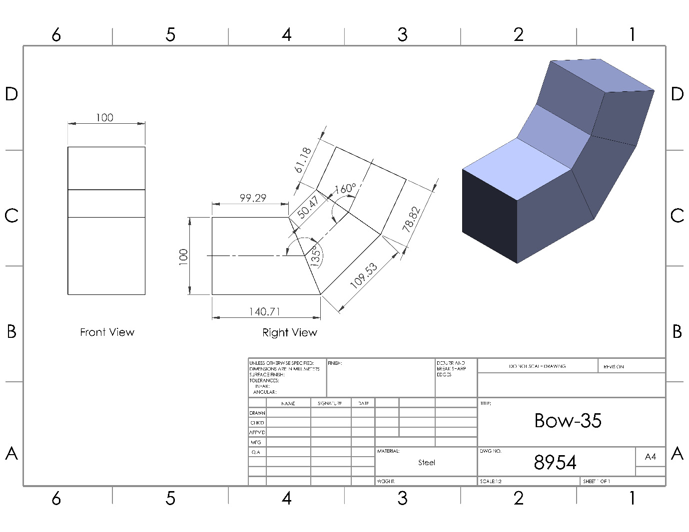
Figure 10.57 – The drawing for question 6
- Create the shown model from scratch and then duplicate the shown drawing (sheet specs: B (ANSI) Landscape, scale: 1:1). The measurements system has been set to MMGS:
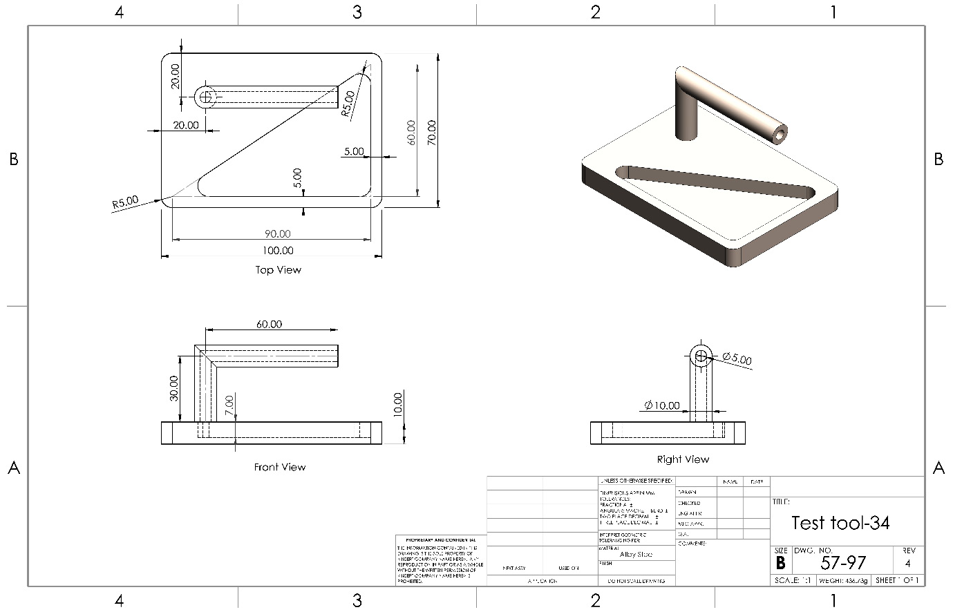
Figure 10.58 – The drawing for question 7
Important Note
The answers to the preceding questions can be found at the end of this book.
Figure 10.18 – Different views that can be directly dragged onto the drawing sheet