
Chapter 4: Special Sketching Commands
Mastering SOLIDWORKS sketching is not only about sketching shapes such as rectangles and ellipses but also depends on other special commands that will greatly enhance our ability to sketch complex shapes faster.
In this chapter, we will introduce sketching commands such as mirroring, offsets, patterns, and trimming. We will also cover examples where we will use multiple shapes and commands to create relatively complex sketches. Even though we can continue without using these commands, they will greatly enhance the efficiency of our sketching creation process.
In this chapter, we will cover the following topics:
- Mirroring and offsetting sketches
- Creating sketch patterns
- Trimming in SOLIDWORKS sketching
By the end of this chapter, you will be able to use the mentioned sketching commands to both optimize and speed up your sketching process.
Technical requirements
In this chapter, you will require access to the SOLIDWORKS software.
Check out the following video to see the code in action: https://bit.ly/3oT1L4I
Mirroring and offsetting sketches
Some of the sketching commands in SOLIDWORKS allow us to easily create more sketch entities based on ones we already have, including circles, rectangles, lines, or any combination of sketch entities. Examples of such sketching commands are mirroring and offsetting. Using these commands will help us avoid creating similar sketch entities more than once. Here, we will start by exploring the mirroring and offsetting sketching commands. We will learn about what these commands do and how we can use them.
Mirroring a sketch
As the name suggests, mirroring a sketch means to reflect one or more sketch entities around a mirroring line. It is very similar to reflecting an image in a mirror. The following figure illustrates the components of mirroring in SOLIDWORKS:

Figure 4.1 – Mirroring a sketch creates a reflection of it around a mirror line
In the preceding diagram, we can see that there are two parts that we need in order to use mirroring:
Since the two shapes are mirror sketch entities of each other, any changes that happen to one shape will automatically be reflected on the other.
To highlight how we can use mirroring, we will create the following shape. Note that the shape is a right-angle triangle with a mirrored reflection and that we will use the Millimeter, Gram, Second (MMGS) measurement system for this exercise:
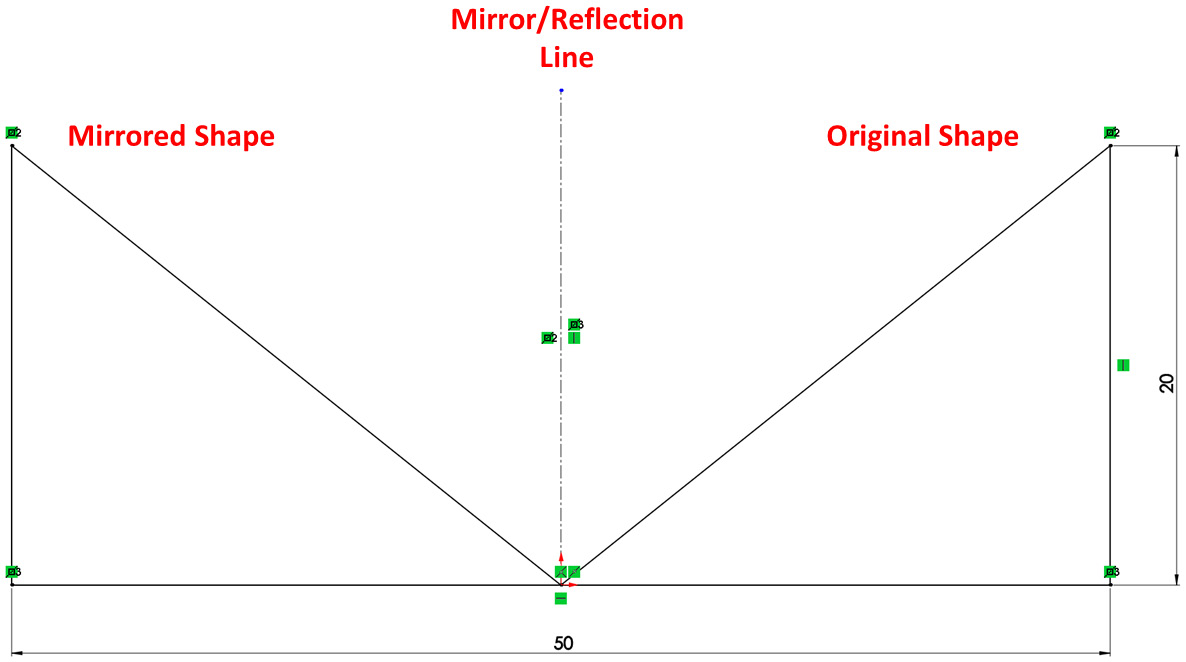
Figure 4.2 – The end result of the sketch mirroring exercise
To create this shape, we need to complete the outlining and defining stages. Here, we will create the base/original sketch and then mirror it. Then, we will define the resulting sketch.
Let's start by outlining our general shape and applying the Mirror Entities command. Follow these steps:
- Sketch the outline of the first triangle and the mirroring line, using a centerline or construction line for the latter:
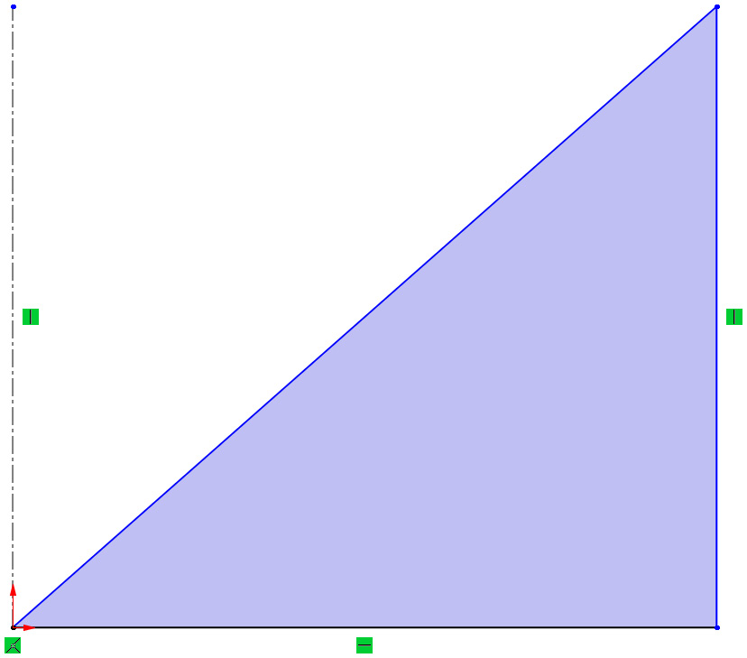
Figure 4.3 – An underdefined outline of a right-angle triangle

Figure 4.4 – The Mirror Entities command
- On the left-hand side, we will see the available Mirror options. For Entities to mirror:, select the three lines that make up the right-angle triangle (L2, L3, and L4). For Mirror about:, select the centerline (L1). Make sure that the checkbox for Copy is also checked. Now, we will see a preview of the triangular mirrored shape on the left. Click on the green check mark to approve the mirroring:
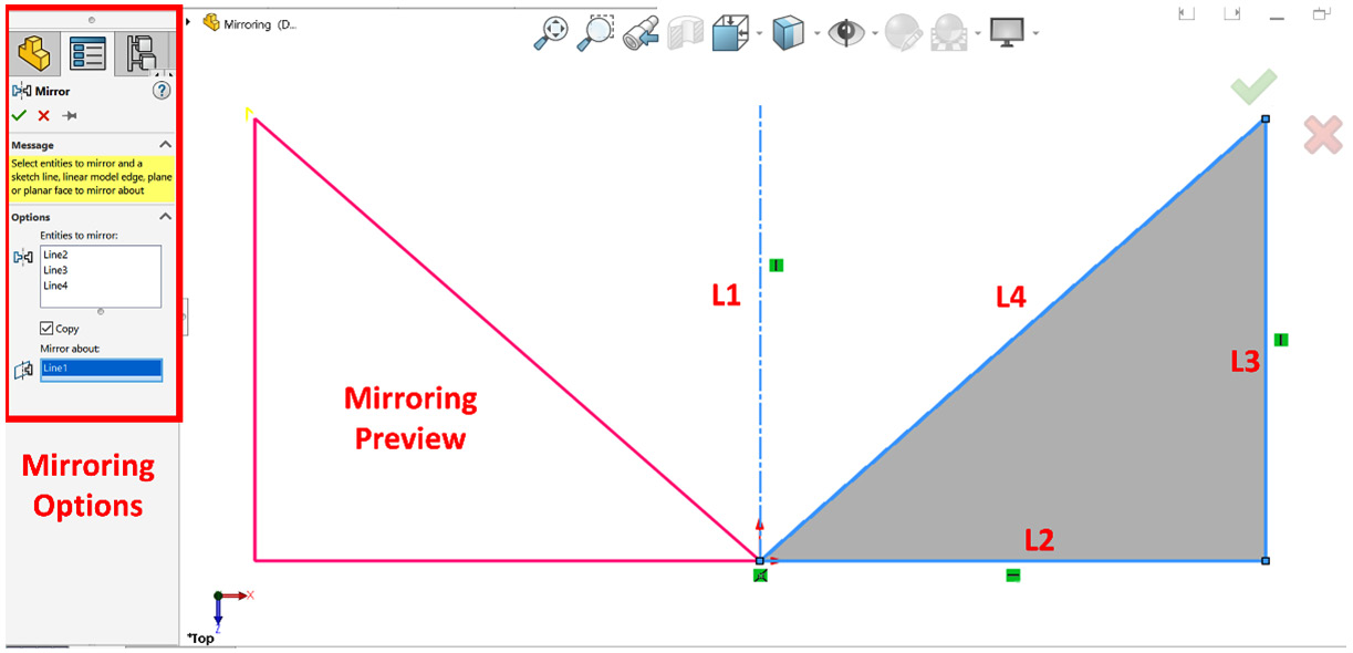
Figure 4.5 – Mirror PropertyManager and preview
To find out more about the mirroring effect, click and hold any of the blue parts of the sketch and move them. You will notice that the mirrored entity will reflect the same movement as the original shape.
Defining mirrored entities
Now that we have our shapes outlined, we can start defining our whole sketch. We can define the sketch by adding the dimensions and relations shown in the following figure. Note that, when defining one line, the mirrored line will also be defined in the same way, as shown in the 20 mm dimension. Also, note that we can add dimensions between the mirrored entities, as shown in the 50 mm dimension. After adding those dimensions, we will notice that it becomes fully defined:

Figure 4.6 – The resulting sketch after fully defining it
In this exercise, we defined the whole sketch after applying the mirror. An alternative approach is to fully define the first triangle before using the Mirror Entities command. In this scenario, the mirrored triangle will also be fully defined, directly after mirroring.
The Copy option in mirroring is used if we wish to keep the original shape. If the Copy option is checked, we will keep the original shape and create a mirrored shape. If it is unchecked, the original shape will be deleted, and we'll be left with the mirrored shape only. In addition, whatever dimensions and relations are on the original shape will be removed.
Tip
Centerline/construction lines are not explicitly required to mirror sketch entities. An alternative to construction lines is to use an existing line in the sketch as a reflection line for mirroring.
This concludes the Mirror Entities sketching command. Note that, in practice, whichever order we outline and define our sketches in can vary. As you gain more experience with sketching, you will have your own approach to doing things. Now, we can start learning about the Offset Entities sketch command.
Offsetting a sketch
Offsetting a sketch allows us to generate sketch entities that are similar to existing ones by shifting the original entities by a certain distance while maintaining all their features. The following figure shows an example of a sketch and its offset. Note that the original sketch is the one we sketch first; after that, the Offset sketch is created by applying the Offset Entities sketch command. The Offset sketch is defined by inputting an Offset Distance:
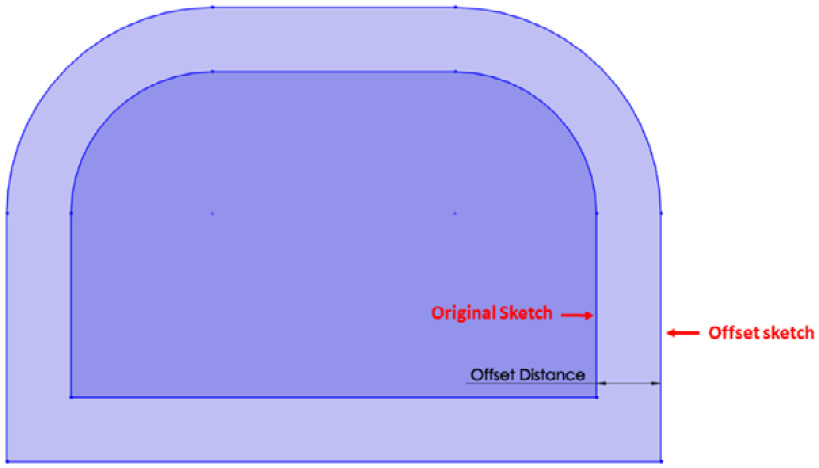
Figure 4.7 – A sketch and its offset
To illustrate how we can create an Offset Distance, we will create the sketch shown in the following figure:

Figure 4.8 – The end result after the offset entities exercise
We will use the MMGS measurement system for this exercise. To sketch the given shape, we will create and fully define the original sketch. After that, we will create the offset sketch using the Offset Entities command. Follow these steps to do this:
- Sketch and define the original sketch using the sketching commands we covered in the previous chapter (Chapter 3, SOLIDWORKS 2D Sketching Basics). The result is shown in the following figure:
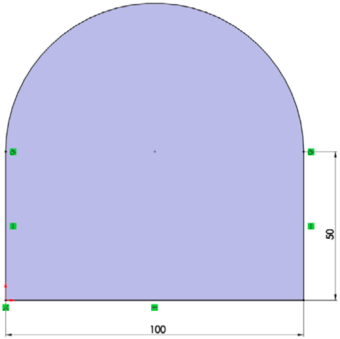
Figure 4.9 – The original sketch before applying an offset

Figure 4.10 – The Offset Entities command
- An options panel for the command will appear on the left-hand side of the screen. From there, we can customize our way of defining our sketch. Set the options that are shown in the following screenshot, which will give us our desired result:
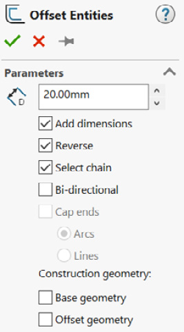
Figure 4.11 – The Offset Entities PropertyManager options
- Select any of the lines in the original sketch we created. A preview will then be shown in the sketch canvas, illustrating the result of the offset. The preview will be shown in yellow, as highlighted in the following figure. Any changes that are made to the options will be reflected in the preview as well:

Figure 4.12 – An offset preview
- Click on the green check mark in the options panel to apply the offset. This will result in the following figure, which matches the final required sketch. Note that the Offset Sketch is already fully defined since our Original Sketch was fully defined as well:
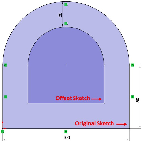
Figure 4.13 – The final result in the offset sketch exercise
This concludes how we can use the Offset Entities sketching command. However, in addition to using the Offset Entities command, we need to learn how to delete an offset and learn about the customization options associated with offsets. Let's explore those.
Deleting an offset
To delete an offset entity, we can select that entity and press Delete on the keyboard. Alternatively, we can right-click on the entity and select Delete. Deleting an offset is just like deleting a normal sketch entity.
Customization options
The following are some of the different options that accompany the Offset Entities command. Those options are displayed on the command's PropertyManager, as shown in Figure 4.11. They allow us to customize the command to best fit our needs:
- Add dimensions: This option makes the offset fully defined upon implementation, as in our previous example. Unchecking this option will create the offset; however, it will not add the offset dimension, thus making it undefined.
- Reverse: This changes the direction of the offset. For example, the default offset of an enclosed circle will be outward, forming a bigger circle. Checking this option makes the offset go onward.
- Select chain: This command helps us select all the sketch entities that are linked together. For example, with this option, selecting one line of a rectangle will automatically select the whole rectangle since the four lines that make up the rectangle are connected. We should uncheck this option if we only want to offset a part of the shape, for example, to offset only one line of a rectangle.
- Bi-directional: This will apply two offsets in two different directions, outward and inward.
- Caps ends: This command is applied when the offset is not an enclosed shape, such as an enclosed rectangle or a circle. The Caps ends option allows us to easily enclose open loops between the original and the offset sketch entities.
- Construction geometry: This allows us to make the original or the offset sketch entities construction entities (for example, construction lines, arcs, and more). Checking Base geometry will switch the original sketch entities into construction entities. Checking Offset geometry will do the same for the offset entities.
This concludes the Offset Entities sketching command. We have learned what the Offset Entities command does and how to use it. We also covered the Mirror Entities sketching command.
To recap, the Mirror Entities command allows us to quickly reflect a copy of a sketch around a reflection line; this means both the original and the mirrored entities will keep imitating each other. The Offset Entities command allows us to create a copy of a sketch entity by offsetting it by a certain distance.
Now, we can start learning about how to create patterns.
Creating sketch patterns
Sketch patterns allow us to easily copy a sketch entity multiple times in a pattern formation. Such sketch patterns can be created in a linear or circular formation. In this section, we will cover creating patterns in both formations.
Defining patterns
Patterns are repeated formations that can be commonly found in consumer products, architecture, fabrics, and more. In patterns, we often have a base shape, sometimes called a base cell or patterned entity, which is created from scratch. Then, the basic shape is repeated multiple times to form a bigger piece. There are two common types of patterns, linear patterns and rotational/circular patterns. Examples of both types of patterns will be shown in this section.
Linear patterns are ones in which you have a base shape (patterned entity) that is repeated linearly in different directions. Linear patterns are commonly found in curtains, carpets, building tiles, floors, and architecture. The following diagram is an example of a linear pattern. The Patterned Entity shape is highlighted with a red square:

Figure 4.14 – An example of a linear pattern
Rotational patterns are ones in which we have a base shape that is repeated as we rotate it. A common application for the rotational pattern is in car rims, as highlighted in the following figure. Within the SOLIDWORKS interface, rotational patterns are known as circular patterns:

Figure 4.15 – An example of a rotational/circular pattern
SOLIDWORKS' pattern tools make it easier for us to create similar linear and circular patterns within sketching. Now that we know what these two types of patterns are, we can start exploring them within SOLIDWORKS, starting with linear patterns.
Linear sketch patterns
Linear sketch patterns allow us to pattern sketch entities in a linear direction. The following sketch shows us how we can define linear patterns in SOLIDWORKS sketching:
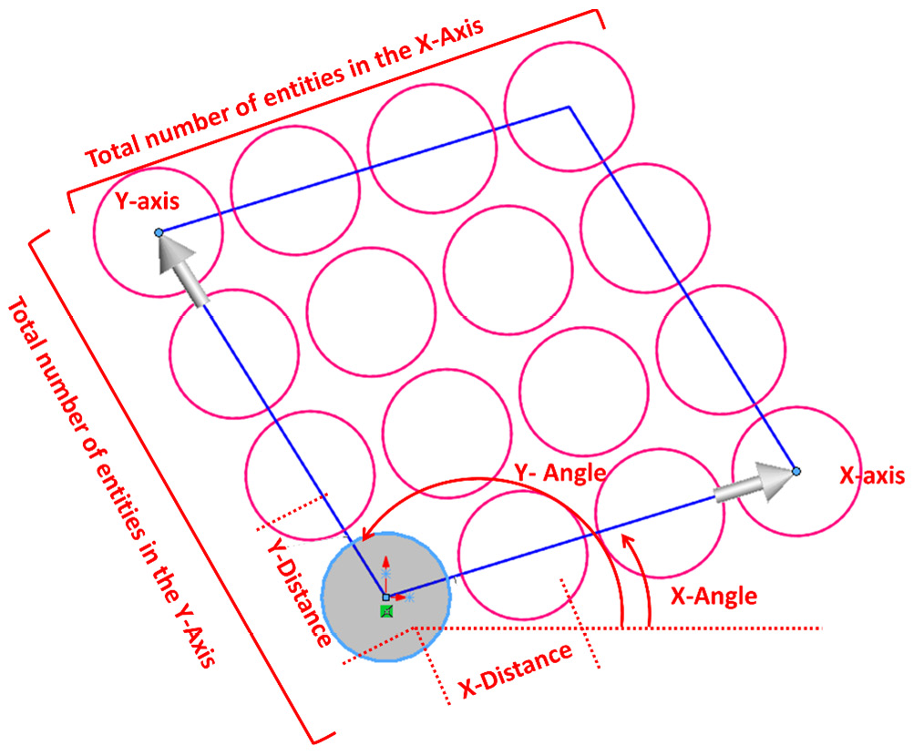
Figure 4.16 – Elements needed to define a linear pattern in SOLIDWORKS
In the preceding sketch, the shaded circle is the base circle, while the other ones are additions to be made with the pattern command. The annotations in writing are the parameters that we need in order to communicate a pattern with SOLIDWORKS sketching. Each of the annotations is repeated twice, one for the X-axis and one for the Y-axis. They are as follows:
- Axes: The X-axis and Y-axis represent the direction in which our pattern is implemented.
- Total number of entities: The number of times we want the entity to be sketched, including the base entity. In the preceding sketch, the number of entities is four for the X and Y directions.
- Distance: This specifies the distance that divides every two entities from each other in a certain direction. In the preceding sketch, they are highlighted as X-Distance and Y-Distance.
- Angle: This specifies how tilted our axes should be since the axes determine the direction of the patterns. Therefore, the whole pattern will shift as we change the direction of an axis. In the preceding sketch, the angles are highlighted as X-Angle and Y-Angle. Note that the X and Y angles start from the same baseline.
Now that we know what elements define a linear pattern, we can start creating one in SOLIDWORKS. To highlight this, we will sketch the following figure. We will use the MMGS measurement system for this exercise:
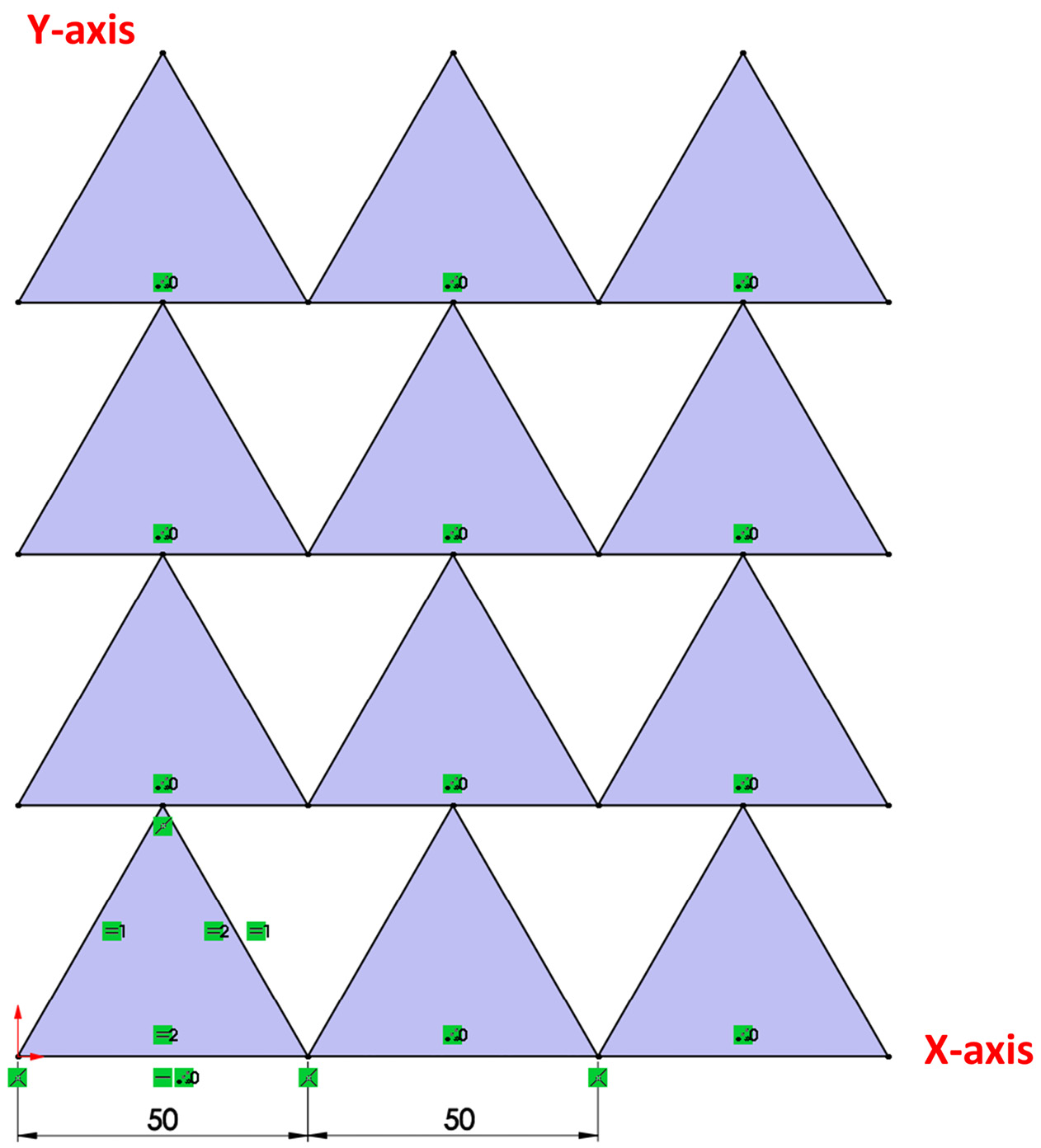
Figure 4.17 – The final result of the linear pattern exercise
To sketch the preceding diagram, follow these steps:
- Sketch and define the base equilateral triangle, as follows:

Figure 4.18 – The base triangle used for the pattern
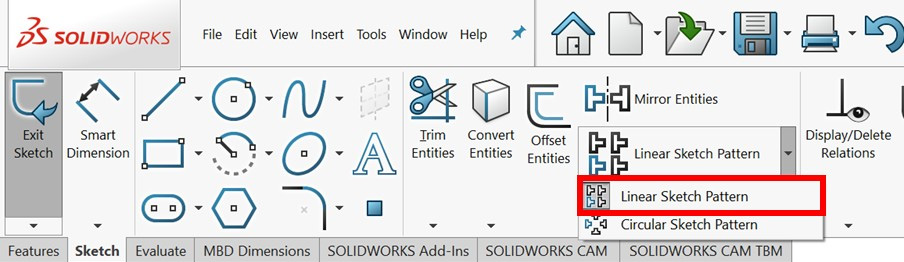
Figure 4.19 – The Linear Sketch Pattern command
- Select the three lines that form our base triangle. Now, we can set up our linear sketch pattern using the options that appear on the left-hand side of SOLIDWORKS. Set the following options:
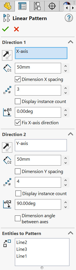
Figure 4.20 – The options for setting a linear sketch pattern
As we are adjusting those options, a preview of the final shape will appear on the canvas. From top to bottom, the options we are using are as follows:
- Direction: For Direction 1, we can see the direction of the X-axis. If we click on the two black and gray arrows next to X-axis, the direction of the pattern will change by 180 degrees. For Direction 2, the direction of the pattern will go along the Y-axis.
- Distance: This determines the distance between every two entities that are adjacent to each other.
- Dimension X spacing: This makes the dimension set a fixed driving dimension. Unchecking this option will not add a dimension to the pattern; instead, the listed dimension in Distance will be the starting point. The Dimension Y spacing option does the same in the second direction.
- Number of instances: This indicates how many times we want an entity to be drawn, including the base sketch.
- Display instance count: Checking this option will show the number of instances on the drawing canvas.
- Angle: This is used to set the direction of X-axis and Y-axis, which governs the pattern's direction.
- Fix X-axis direction: Checking this option will make the angle a driving dimension. Unchecking this option will not add the angle direction to the pattern; therefore, we need to identify it separately.
- Dimension angle between axis: Checking this option will make the angle between the x and y axes a driving dimension. This option is used to define the Y-axis direction in our canvas.
- Entities to Pattern: This lists all the entities that will be patterned with the command. We can delete entities by deleting them from the list. We can add entities by selecting them in the sketch canvas.
Our preview may look something like the following figure:
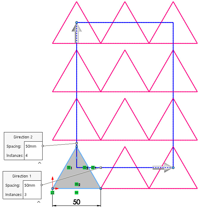
Figure 4.21 – The resulting preview of the pattern
- After adjusting these options, we can click on the green check mark. We will see the following shape. Note that the first row of triangles in the x direction is fully defined, while the other triangles extending in the y direction are not. To understand how such patterns work, we can click and drag the blue parts around our screen. We will see that all the patterned shapes move together:
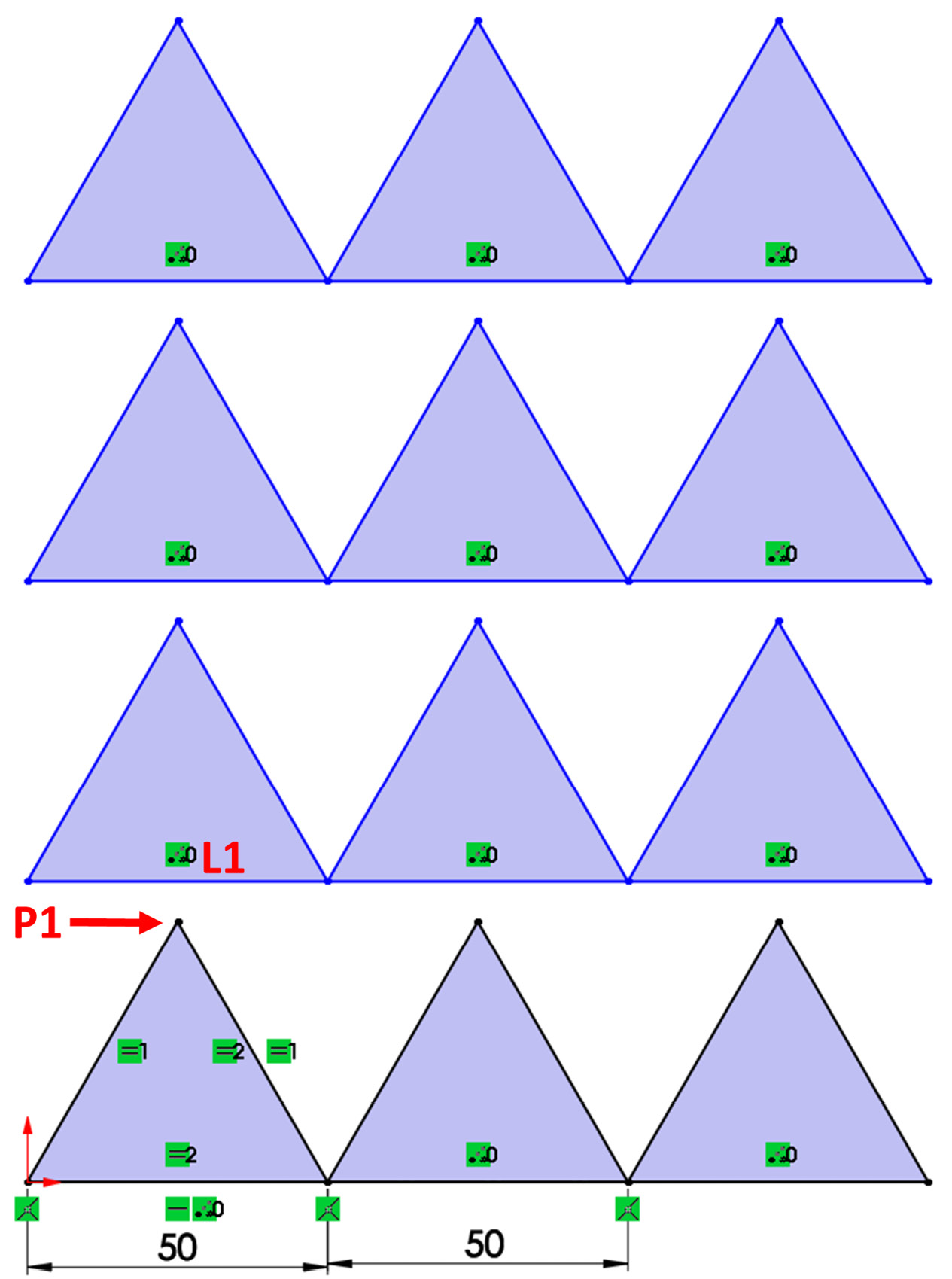
Figure 4.22 – The pattern might not be fully defined after application
- To fully define the pattern, we can define the shapes in the y direction. We will need to add a midpoint relation between L1 and P1. This will make the sketch fully defined, as shown in the following diagram.
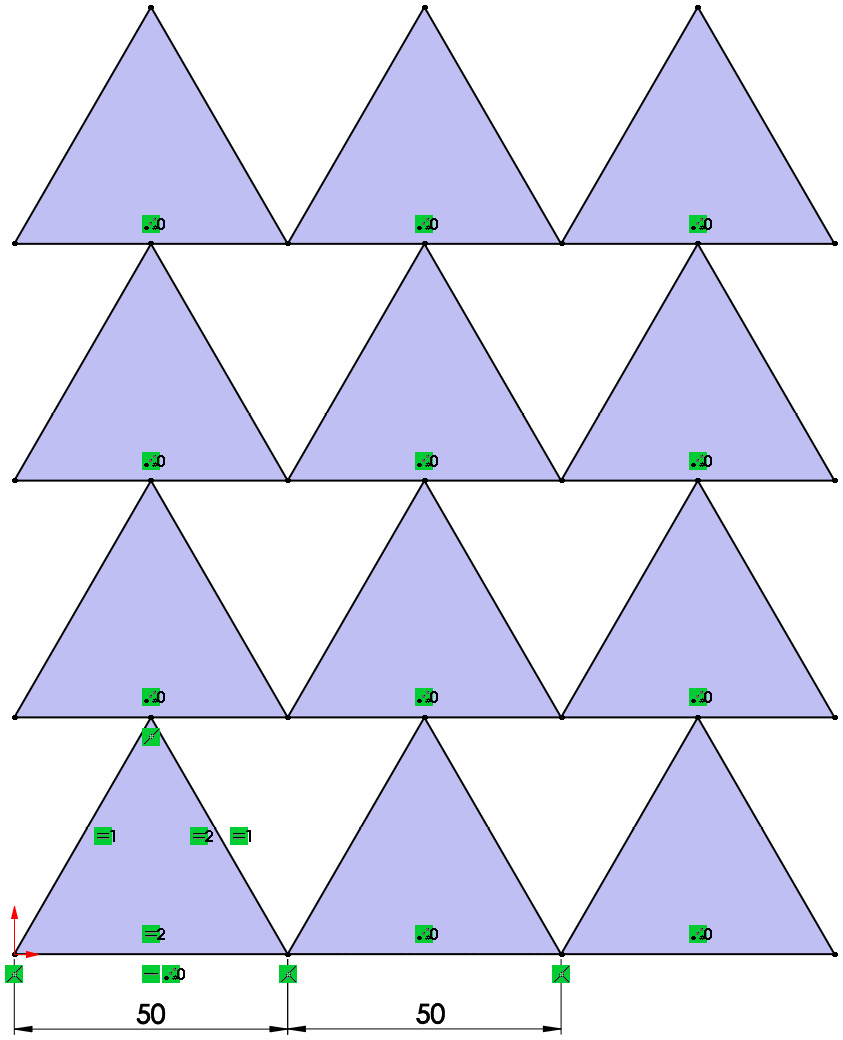
Figure 4.23 – The final result of the linear sketch pattern exercise
Tip
We can also define a dimension for the y-direction pattern using the Linear Pattern command PropertyManager, as shown in Figure 4.20, by checking the Dimension Y spacing option. However, in the exercise, we used a relation to define the Y-axis pattern.
Let's have a look at some related commands:
- Instances to Skip: At the bottom of the Linear Pattern PropertyManager options, we will find the Instances to Skip option. We can use this to skip instances of the pattern. For example, in the preceding exercise, we can remove the two middle triangles by adding them to Instances to Skip. This will exclude the middle triangles from the pattern:

Figure 4.24 – The Instances to Skip option in sketch patterns
- Edit Linear Patterns: To edit an existing linear pattern, we can right-click on any of the patterned instances and select the Edit Linear Pattern option, as shown in the following screenshot:
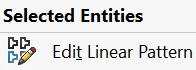
Figure 4.25 – The Edit Linear Pattern command
- Delete Linear Patterns: To delete the pattern (or parts of it), we can simply select or highlight those entities and press Delete on the keyboard.
This concludes this exercise on using linear patterns. In the exercise, we have covered the following topics:
- How to set up and define linear patterns
- The different options that we can use to define a linear pattern
- How the linear pattern entities interact as under defined entities
Now that we have mastered linear patterns, let's move on and look at circular patterns.
Circular sketch patterns
Circular sketch patterns allow us to pattern sketch entities in a circular direction. The following figure highlights how we can define a circular pattern in SOLIDWORKS sketching:

Figure 4.26 – The elements needed to define a circular pattern
In the preceding sketch, the shaded circle is the base circle, while the others are additions to be made with the pattern command. The annotations in red are the parameters that we need in order to communicate a pattern to SOLIDWORKS sketching. The following is a small description of the different annotations in the preceding figure:
- Center: This represents the center of rotation for the circular pattern. This can be determined with specific x and y coordinates or by relating it to another point.
- Radius: This is the distance between the original entity and the center of the pattern.
- Angle: A1: This is the angle between two adjacent patterned entities.
- Total Angle: A1: This is the angle between the original and the last patterned entity.
- Angle: A2: This is the angle between the original patterned entity and the center.
- Number of patterned entities: This shows the total number of patterned entities, including the base sketch.
To illustrate how to use circular sketch patterns, we will create the following sketch, using the Inch, Pound, Second (IPS) measurement system in this exercise:

Figure 4.27 – The final result of the circular pattern exercise
To sketch the preceding diagram, follow these steps:

Figure 4.28 – The base sketch for the circular pattern
- Select the Circular Sketch Pattern command from the Sketch command bar:
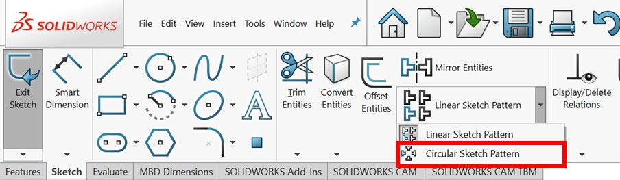
Figure 4.29 – The Circular Sketch Pattern command
- Select the three lines that form our base sketch. Now, we can set up our circular pattern using the options that appear on the left-hand side of SOLIDWORKS. Set the options that are shown in the following screenshot:
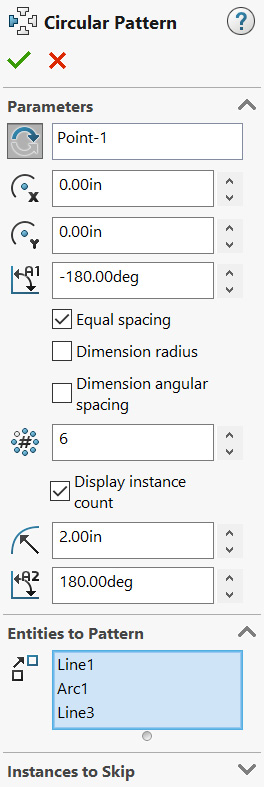
Figure 4.30 – The Circular Pattern options relating to this exercise
As we are adjusting those options, a preview of the final shape will appear on the canvas. From top to bottom, the options we will be using are as follows:
- Center: This field starts as Point-1 and represents the center of the pattern. By default, the center of the pattern will be the origin; however, we can change it by selecting other points. Rotational direction, which is to the left of the Point-1 selection, is a button that will flip the direction of the rotation.
- X and Y center locations: The two fields marked with X and Y represent the location of the center of our circular pattern. Since our center is the origin, the location is marked as 0.00 inches for the x and y directions. We can use these fields to set up an exact center in the coordinate system.
- A1 angle: This defines the angle that will govern the locations of the circular pattern. In our example, it is set as -180 since the pattern goes counterclockwise by 180 degrees. Note that this does not define the dimension; instead, it helps us approximate the location and the look of the pattern. We can fully define the pattern after its implementation.
- Equal spacing: This will ensure that all the patterns are equally distributed in the angle range.
- Dimension radius: This will add a driving dimension to the radius of the pattern. Note that this is not needed if we merge the center with a fixed point, such as the origin.
- Dimension angular spacing: Checking this option will allow us to dimension the angle between the adjacent patterned instances, instead of the angle between the base sketch and the last patterned entity.
- Number of patterned instances: This indicates how many times we want the entity to be drawn or patterned, including the base sketch.
- Display instance count: Checking this option will show the number of instances on the drawing canvas.
- Radius: This allows us to linearly increase or decrease the radius between the patterned entities and the center.
- A2 angle: This will shift the center of the pattern so that it's at a certain angle.
- After adjusting these options, we can click on the green check mark. This will give us the following shape:
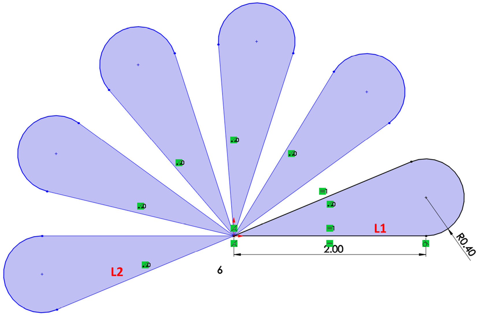
Figure 4.31 – The resulting sketch after applying the pattern might not be fully defined
Important Note
The pattered entities are not fully defined. To understand how circular patterns work, we can click and drag the blue parts of the sketch around. We will see that the patterned shapes move together.
- Set the angle between L1 and L2 so that it's equal to 180 degrees. Doing this will fully define the sketch, as shown in the following figure:
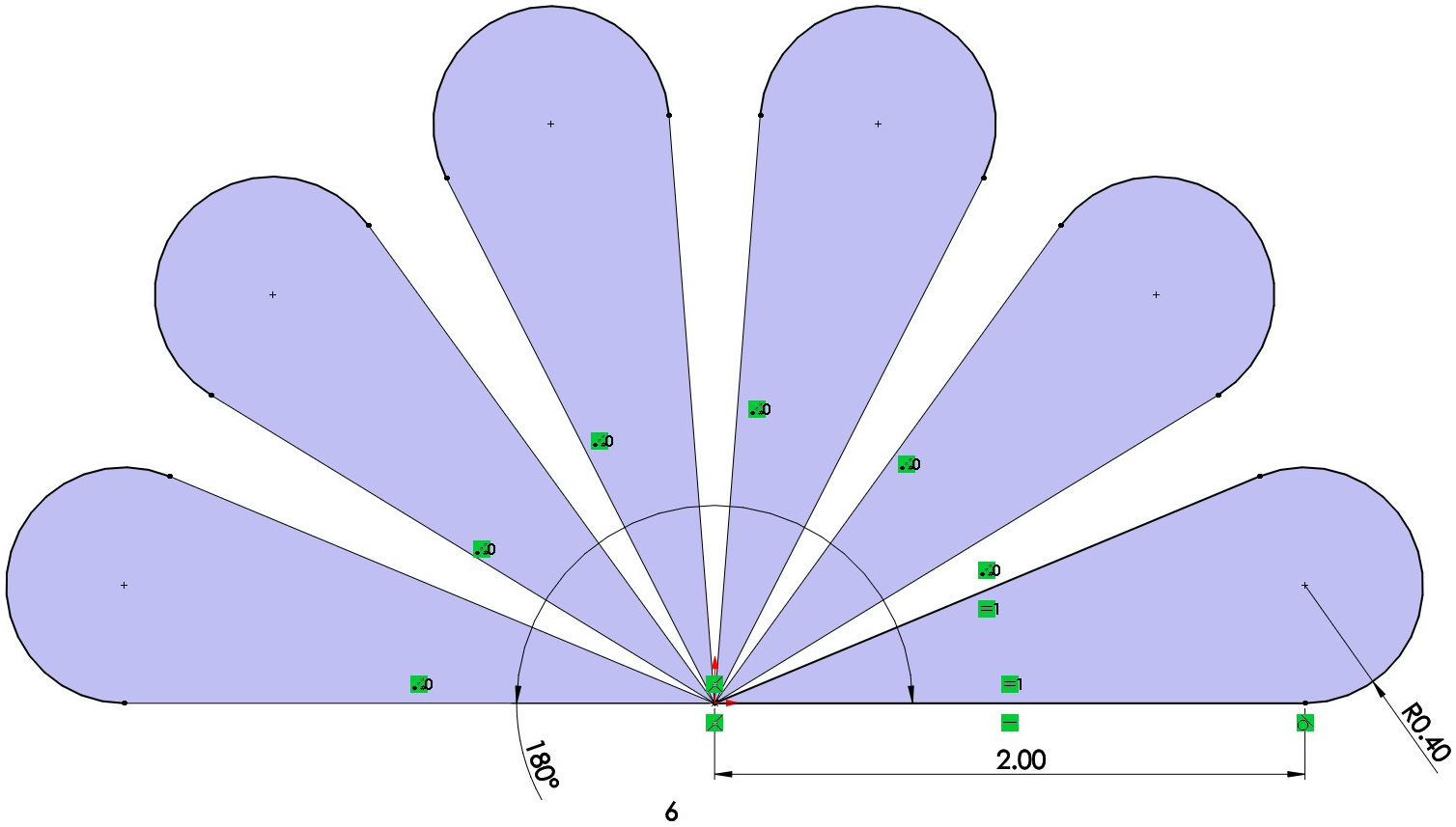
Figure 4.32 – The final resulting sketch from the exercise
Similar to linear patterns, we have the option of skipping instances, editing the circular patterns, and deleting instances. To do these things, we can follow the same procedure that we followed for linear patterns.
This concludes this exercise of using circular patterns. In the exercise, we have covered the following topics:
- How to set up and define circular patterns
- The different options that we can use to define a circular pattern
- How the circular pattern entities interact with each other as under defined entities
In this section, we talked about linear and circular sketch sketching patterns. Both allow us to quickly repeat a selection of sketch entities multiple times, saving a lot of time and energy. A linear pattern is allowed to pattern entities linearly while a circular pattern allowed us to pattern entities rotationally. We can also use both linear and circular patterns to build one sketch. However, we have to apply them separately. Now, we can start looking at another special sketching command – trimming.
Trimming in SOLIDWORKS sketching
Trimming in SOLIDWORKS allows us to easily remove unwanted sketch entities or unwanted parts of sketch entities. This makes it easier for us to create complex sketches. In this section, we will cover what trimming is, why we use trimming, and how to use trimming within SOLIDWORKS.
Understanding trimming
Trimming allows us to delete parts of sketches that are unwanted. This makes it easier to create complex sketches that go beyond the standard sketch commands. This is because it makes it easier to utilize segments from different sketching commands. To explore this further, let's examine the following sketch and how the trimming command can help create it:
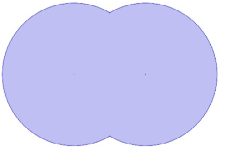
Figure 4.33 – Trimming allows us an easy or alternative way to sketch this
We can start this simple sketch by sketching two circles, as shown in the following figure. After that, we can trim/remove the interfering parts to get our desired shape:

Figure 4.34 – Trimming unwanted sketch entities can get us new shapes
Also, depending on the sketch we want, trimming could make it easier for us to define the sketch according to our specific design intent. Now that we know what trimming is, we can start using the command.
Using power trimming
To show you how we can use the trimming tool in SOLIDWORKS, we will create the following sketch, which consists of a circle and a rectangle. We will use the MMGS measurement system for this exercise:

Figure 4.35 – The end result of the power trim tool exercise
To create the given sketch, follow these steps:
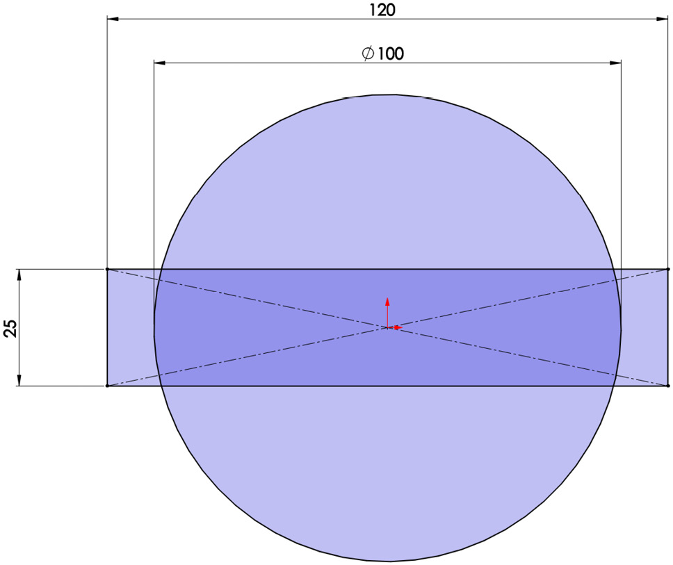
Figure 4.36 – Original sketches with different intersecting enclosures

Figure 4.37 – The Trim Entities command
- After selecting this command, the PropertyManager for it will appear on the left of the interface. This will show different types of trimming tools. Here is a brief description of the different trimming tools that are available:
- Power trim: This is the easiest method for trimming entities. Power trim is a multipurpose trimming tool that allows us to cut entities by going over them in the canvas. Power trim is what we will use in this section.
- Corner, Trim away inside, Trim away outside, and Trim to closest: These are the different and more specific ways we can trim. A Corner trim makes it easier to trim two entities till they intersect at a projected corner. Trim away inside allows us to trim an entity that lies inside bounding entities, while Trim away outside allows us to trim entities that lie outside bounding entities. Trip to closest trims an entity to its closest two boundaries. We will utilize these specific trim options in this book.
- Keep trimmed entities as construction geometry: When checked, trimming will not remove entities from the canvas. Instead, they will be converted to construction lines.
- Ignore trimming of construction geometry: When checked, trimming will not function with construction lines.
As shown in Figure 4.38, we have picked Power trim and, as we didn't want to revoke the construction lines that define our rectangle, we checked the Ignore trimming of construction geometry option:
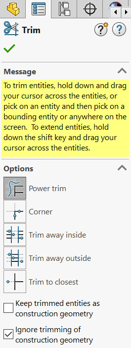
Figure 4.38 – The different options in the Trim Entities PropertyManager
- Go back to the canvas and start trimming. To trim unwanted parts, we can click, hold, and move the mouse, as illustrated by the red lines in the following diagram:

Figure 4.39 – The lines indicating the needed movement of the power trim to trim unwanted entities
As we cross each of these lines, we will notice that the line will disappear. By doing this, we will only remove the lines that are not desirable. If we trim the wrong line, we can simply undo this by pressing Ctrl + Z. After doing this, we will end up with the final shape, which was shown at the beginning of this section.
Tip
After trimming an entity using the power trim command, a small red square will appear after each trim. Moving the mouse back to that red rectangle will undo that trim.
This concludes this exercise on trimming entities using SOLIDWORKS. In this exercise, we have covered the following topics:
- How to set up the Trim Entities command
- How to use trimming to get our desired result
The trimming tool can be used as an enhancement tool; we can always create a certain sketch out of it. However, the tool can greatly enhance our sketching abilities by allowing us to create certain sketches faster.
Summary
In this chapter, we covered different sketching commands that can enhance our sketching capabilities. These included sketch mirrors, which allow us to generate mirrored sketch entities around a mirror line. We also covered offsetting, which allows us to generate duplicated sketch entities at an offset. Then, we learned about linear and circular patterns, which allow us to create many instances of a sketch entity in a specified pattern. Finally, we covered trimming tools, which allow us to remove unwanted parts of our sketches.
In the next chapter, we will cover our first set of features. So far, we've only learned about 2D sketches. Features will allow us to turn our 2D sketches into 3D models.
Questions
Answer the following questions to test your knowledge of this chapter:
- What does mirroring a sketch do?
- What are patterns, and what are the different types of patterns we can make in SOLIDWORKS?
- What is trimming in SOLIDWORKS sketching?
- Sketch the following diagram using the MMGS measurement system:

Figure 4.40 – The resulting sketch from question 4
- Sketch the following diagram using the IPS measurement system:

Figure 4.41 – The resulting sketch from question 5
- Sketch the following diagram using the IPS measurement system (tip – use ellipses):
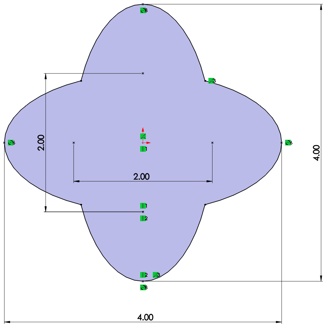
Figure 4.42 – The resulting sketch from question 6
- Sketch the following diagram using the MMGS measurement system:

Figure 4.43 – The resulting sketch from question 7
Important Note
The answers to the preceding questions can be found at the end of this book.