
The best way to learn how to animate is to jump right in and start animating. You will begin this chapter by picking up the Mobile exercise from Chapter 2, "Your First Max Animation," and adding animation to the shapes of the mobile. You'll take a good look at 3ds Max's animation tools so you can start editing animation and training your timing skills.
Topics in this chapter include:
Hierarchy in Animation: The Mobile Redux
Using Dummy Objects
The Bouncing Ball
Using the Track Editor-Curve Editor
Track View
Anticipation and Momentum in Knife Throwing
Do you remember way back when you were reading Chapter 2? Those were good times, weren't they? After setting up the mobile in that exercise, you animated only the bars to rotate, but you left the rotation of the shapes for later. In this chapter, you'll pick up where you left off with the mobile from Chapter 2 and finish the animation using the hierarchies that were set up in that exercise.
Note
If you skipped the Mobile exercise in Chapter 2, you may want to try it now before you move on with this animation exercise. Understanding hierarchies and how they work in animation is extremely important.
If you haven't already done so from the previous Chapter 2 exercise, copy the Mobile project from the companion CD to your hard drive. Set your Max project folder by choosing File → Set Project Folder and selecting the Mobile project that you copied from the CD to your hard drive.
Animating the Shapes
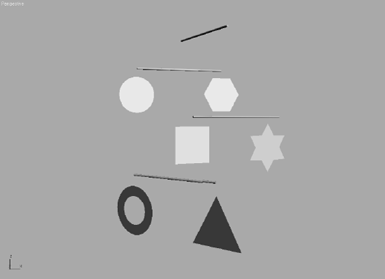
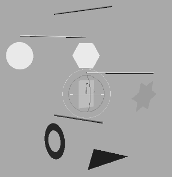
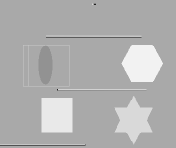
With the Mobile_v05.max scene open (or your own file), scrub through the animation to become familiar with the scene. The intent here is to create a hierarchy in the mobile and animate the bars. Now you will add rotation to the shapes hanging from the bars. Figure 8.1 shows the mobile in mid-animation.
To add animation to the shapes under the bars, follow these steps:
Go to frame 0 of the animation, and click the Auto Key button (

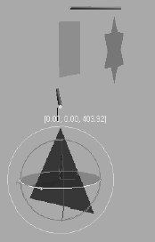
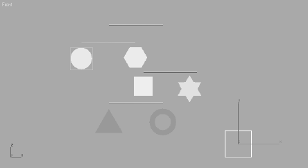
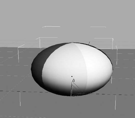
Select the triangle hanging from the bottom bar, and go to frame 50. Rotate the triangle in the Z-axis in either direction at least a full turn of 360 degrees, if not a lot more, as shown in Figure 8.2. Don't scrub your animation yet.
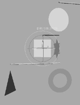
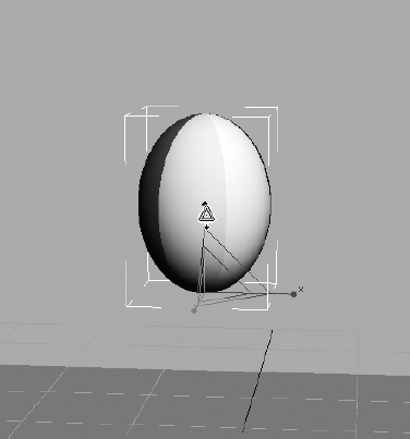
Still at frame 50, select the square on the bar above, and rotate that shape in the Z-axis several hundred degrees in either direction. Figure 8.3 shows the rotation of the square. The bottom bar goes along with the square's rotation because this is how they were linked in Chapter 2. Don't scrub your animation yet.
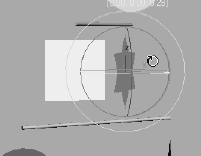
Still at frame 50, select the star and rotate it several hundred degrees on the Z-axis in either direction (Figure 8.4).
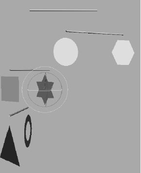
Now scrub your animation and check the results. In theory, all the bars should rotate and so should the shapes hanging on the bars. When you scrub, however, the mobile will seem to have lost its mind. The shapes will rotate completely off axis, as if you have set rotation keyframes on the X- and Y-axes as well as the intended Z-axis. The same will occur with the lower bar. It will go off its axis and rotate in an unpredictable manner. This behavior is explained in the next section, with easy solutions to fix the issue.
Making a Mistake
Why would we purposely show you an incorrect workflow? Because learning from missteps is as important to learning CG as learning the correct steps. Being able to troubleshoot is essential to becoming good in CG, and the more trouble you get yourself into, the better you will become at digging your way out.
This example of strangely rotating hierarchies is an isolated issue that is called gimbal lock in many CG circles. Different CG packages have different ways of interpreting exactly how an object rotates when it is rotating along more than one axis. Imagine three cars all staring each other down at a three-way intersection—with the traffic light out. Who goes first in this situation is important to the flow of traffic at the intersection. When a 3D package calculates rotations, it needs to know which axis to rotate first before tending to the rotation of the other axes. In 3ds Max, the animation controller is the traffic light directing the animation. With gimbal lock, you have an incorrect interpretation of the rotations, so the resulting animation seems off axis.
In this exercise, the multiple rotations inherited by the children shapes and bars from their parents caused havoc with their own rotations, so the axes became confused and everything looks just plain wrong. The easiest way to fix this issue is to reassign the animation controllers in charge of the rotations for those objects to one that will not lock up.
Animation Controllers
By default, 3ds Max assigns a Euler XYZ controller to the rotations of objects. This is the best controller to use in the majority of circumstances. In this example, however, it doesn't quite work. To assign a different controller, follow along here:
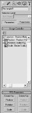
Select the square; you will start with that object. Switch to the Motion panel (click the Motion Panel tab (

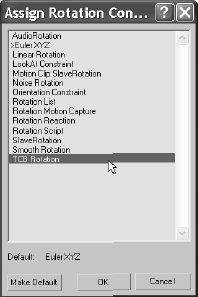
Select Euler XYZ from the list in the Motion panel, as shown in Figure 8.5. Click the Assign Controller button (

The square and the bar linked beneath it should snap back into axis. Scrub the animation, and you'll see that the square and the bar beneath it are not behaving as you would expect: They are rotating on the Z-axis only, as they should. Figure 8.7 shows the resulting animation. Notice that the star and triangle are still rotating off axis.
Select the triangle and repeat steps 2 and 3 to assign a TCB Rotation controller to the triangle. Do the same for the star. Figure 8.8 shows the proper rotations of the shapes and the bars—but looks are deceiving. We're not done yet!
If Euler XYZ caused such a ruckus, why isn't TCB Rotation the default for rotating objects? For one thing, the editing options you have with a Euler XYZ controller are head and shoulders above what you get with TCB Rotation. With the Euler XYZ, 3ds Max splits the XYZ rotation animation into three separate tracks to give individual control over each axis. This is ideal.
In addition, the TCB Rotation has taken the several hundred degrees of rotation you have animated, and cut it down to within 180 degrees of rotation at most. The square, triangle, and star don't seem to be rotating the several hundred degrees you intended.
Note
It is not a good idea to change the default animation controllers based solely on your experience with this exercise. On the other hand, if you run into a gimbal lock situation in the future, you'll have a good idea what caused it, and you'll be able to troubleshoot it quickly.
Editing the TCB Rotation Keyframes
To fix the problem that the objects do not rotate the several hundred degrees you want, you will have to manually edit the controller to allow a greater degree of rotation:
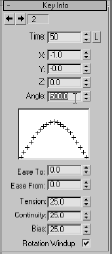
Select the square and open the Key Info rollout (Figure 8.9).
The Key Info rollout shows you the properties of the animation on the selected object on a key-by-key basis. If everything is grayed out, use the arrows at the top of the rollout to move through the keyframes. Go to the first keyframe at frame 0 (shown as Time: 0 in the rollout). The Angle displays the orientation of the square at the beginning of the animation: 120. Use the arrows again to move to keyframe 2 (Time: 50).
The Angle parameter should change to a value of 117.643 (your value may differ slightly). The X parameter value reads −1.0. The X, Y, and Z parameters represent the direction in the respective axes. The value −1 means the square is rotating backward. Don't get confused because this value is now in X and not Z. Remember, you gave up the individual controls for X, Y, and Z when you changed from the Euler XYZ controller. While at this second keyframe, click Rotation Windup at the bottom of the rollout, and enter the value 500 for Angle. You must first turn on Rotation Windup to enter 500 for the Angle (Figure 8.10).
Scrub your animation, and the square will rotate more, as you first intended. Repeat steps 2 and 3 for the triangle and star to fix their rotations with the TCB Rotation controller. At this point, you can save the 3ds Max file for use in the next section.
Any parameter that is animated has a controller. A controller essentially deals with all the animation functions in the scene for 3ds Max, such as storing keyframe values. Interpolating in-betweens is handled by the controllers. By default, the Position XYZ controller is assigned to an animation on an object's position and a Euler XYZ is assigned to its rotation. These controllers are the most useful as they split the X, Y, and Z into separate tracks to give individual control over each axis. You will have the opportunity to work with and edit individual tracks later in this chapter.

Another way to circumvent this particular issue of rotation confusion is by using helper objects in 3ds Max called dummy objects. Changing the controller for an object is not always the best solution—particularly if the range of movement will be changed. You saw this problem when you changed to TCB Rotation before you had to fix it in Key Info to add more rotation. Using dummy objects, you can insert a helper in the hierarchy that will negate the gimbal lock issue and make it very clear to 3ds Max how the rotations should proceed. As a matter of fact, it's common for animators to make copious use of dummies as controllers for their animation rigs. A rig is essentially any setup in the scene that helps you animate objects in the scene.
Dummies (called null nodes in other CG applications such as Maya) are very useful nonrendering objects that can be used in several ways. In this case, they serve as placeholders and are used directly in the hierarchy to straighten out the rotation confusion. They serve as parents to the mobile shapes that may come down with rotation confusion or gimbal lock.
Placing Dummies in the Mobile
To create dummy objects for the animation hierarchy, follow these steps:
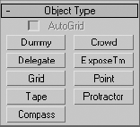
Go to the Create panel. In the Helpers (

There are no Parameter rollouts or settings for the dummy. Move your cursor to the Front viewport, center it over the circle, and then click and drag to create. Create a dummy that is slightly larger than the shape.
Linking the Dummies
If you scrub the animation, you will notice that the circle moves along with the rotation of its parent bar, as it did before. This is because the dummy is not part of the hierarchy yet. You are going to change the structure of the hierarchy in order to break the relationship of the circle with its parent object and restructure it to add the dummy between the bar and the circle. This is done by relinking the new order.
Make sure the Time slider is at frame 0. Go to the main toolbar and click on the Select and Link tool (

Note
To jump to the beginning of an animation, just press the Home key on your keyboard; this is a shortcut to jump to the start. Likewise, pressing the End key will take you to the end of an animation.
You're not done yet. If you scrub the animation, the circle will no longer move with its parent bar. You have to link the dummy to the bar. Select the dummy, and click and drag to the Parent cylinder (Figure 8.12). This completes the new hierarchy. Now the circle is the child of the dummy, and the dummy is the child of the parent bar above it. Play the animation, and you will see the dummy moving along with the mobile, with the circle in tow.
Fantastic! Now it is time to animate the circle shape itself. Move to the end of your timeline (frame 100, press the End key), and click the Auto Key button at the bottom of the interface (you can also press the N key to toggle Auto Key on and off). Select the circle, and rotate a few hundred degrees on the Z-axis in either direction. Do not rotate the dummy, just the circle. Figure 8.13 shows how the circle rotates within the dummy, which then follows with the bar's rotation.
Repeat steps 1 and 2 to create dummies for the other shapes in the mobile. Relink the shapes to their dummies, as you did in steps 3 and 4. Animate the shapes themselves to your heart's content. If you see funky rotation on the dummies and shapes, either To jump to the beginning of an animation, just press the Home key on your keyboard; this is a shortcut to jump to the start. Likewise, pressing the End key will take you to the end of an animation. Figure 8.12 Drag the circle to the dummy object, and then drag the dummy to the cylinder. you have made an error in the linking order, or you have animated the dummies rotating and not the shapes themselves.


Play the animation. As you can see, the funky rotation is gone and now you have a perfectly normal rotation. The bar's rotation moves the dummy below it, and the dummy pulls the circle. Because the bar is not directly pulling the circle, the circle is free to rotate without rotation confusion.
Once you feel confident with how this exercise works, you should have a pretty solid idea of how hierarchies work in animation. Feel free to go through this entire exercise another time before moving on.
Editing Dummies
Each dummy gets its orientation from the viewport in which you create it. When you place one of the mobile's dummies, you don't need to have it aligned perfectly with the shape for which the dummy is being used. However, it is a good idea to match things up as best as you can to keep track of which dummy goes with which shape.
Let's say you created a dummy and it is nowhere near its shaper. The Align tool can move the dummy so it is centered on the shape. To see how the Align tool works, follow along with these steps:
Create a dummy of any size anywhere in the mobile scene (Figure 8.14).
Make sure the dummy is selected. Go to the main toolbar and select the Align tool (

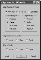
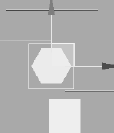
The Align Selection dialog gives you the choice of aligning an object along any axis, orienting the object (this feature is for rotations), and aligning for the object's scale. Keep the checks in the X,Y,Z position, but change the Current and Target Object to Center and then press OK. The dummy will match up with the shape as shown in Figure 8.16.
Although it may seem like more work, using dummies is a great workflow for animation. It keeps the scene's animation neater and better defined. As you gain more experience, you will begin to learn when you should use dummies in your hierarchy to make the animation workflow smooth.
A classic exercise for all animators is creating a bouncing ball. As a matter of fact, you will find bouncing ball tutorials almost everywhere you look. Although you will see it as a straightforward exercise, there is so much you can do with a bouncing ball to show character, that the possibilities are almost limitless. Animating a bouncing ball is a good exercise in physics, as well as cartoon movement. You'll first create a rubber ball, and then you'll add cartoonish movement to accentuate some principles of the animation techniques discussed in Chapter 1, "Basic Concepts." Aspiring animators can come use this exercise for years and always find something new to learn about bouncing a ball.
In preparation, copy the Bouncing Ball project from the CD to your hard drive. Set your current project by choosing File → Set Project Folder and selecting the Bouncing Ball project that you copied from the CD to your hard drive.
Animating the Ball
Your first step is to keyframe the positions of the ball. As introduced in Chapter 1, keyframing is the process—borrowed from traditional animation—of setting positions and values at particular frames of the animation. The computer interpolates between these keyframes to fill in the other frames to complete a smooth animation.
You'll start with the gross animation, or the overall movements. This is also widely known as blocking. First, move the ball up and down to begin its choreography.
Follow these steps to animate the ball:
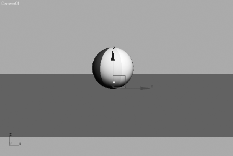
The first thing you need to do in this scene is to move the pivot point for the ball. Go to the Hierarchy panel (

Turn on the Auto Key button (keyboard shortcut N) and move the timeline to frame 10. Select the ball and move it along the Z-axis down to the ground plane. That will be 0 units in Z when you release the mouse button in the Transform type-ins on the bottom of the interface. You can also just enter the value and press Enter (Figure 8.17).
This has created two keyframes, one at frame 0 for the original position the ball was in, and one at frame 10 for the new position to which you just moved the ball.
Copying Keyframes
Now you want to move the ball up to the same position in the air as it was at frame 0. Instead of trying to estimate where that was, you can just copy the keyframe at frame 0 to frame 20.
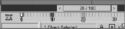
You can see the keyframes you created in the timeline. They are red tick marks in the timeline. Red keys represent Position keyframes, green keys represent Rotation, and Blue keys represent Scale. When a keyframe in the timeline is selected, it turns white. In Figure 8.18, the keyframe at frame 0 is selected and is white.
Select the keyframe at frame 0; it should turn white when it is selected. Hold down the Shift key on the keyboard (this is a shortcut for the Clone tool), and click and drag the selected keyframe to move it to frame 20. This will create a keyframe with the same animation parameters as the keyframe at frame 0.
Click and drag on the Time slider to scrub through the keyframes.
Right now the ball is going down and up.
To continue the animation for the length of the timeline, you could continue to copy and paste keyframes—but that would be very time-consuming, and you still need to do your other homework and clean your room. A better way is to loop or cycle through the keyframes you already have. An animation cycle is a segment of animation that is repeatable in a loop. The end state of the animation matches up to the beginning state, so there is no hiccup at the loop point.
In 3ds Max, cycling animation is known as Parameter Curve Out-of-Range Types. This is a fancy way to create loops and cycles with your animations and specify how your object will behave outside the range of the keys you have created. This will bring us to the Track View, which is an animator's best friend. You can go through the Track View's UI in the "Track View" section later in this chapter at any time, or you can hang tight and see how you work with Track Editor first using the Bouncing Ball exercise. You will learn theunderlying concepts of the Track Editor throughout this exercise as well as its basic UI. Feel free to reference the "Track View" section as you continue.
The Track View is a function of two animation editors, the Curve Editor and the Dope Sheet Editor. The Curve Editor allows you to work with animation depicted as curves on a graph that sets the value of a parameter against time. The Dope Sheet Editor displays keyframes over time on a horizontal graph, without any curves. This graphical display simplifies the process of adjusting animation timing because you can see all the keys at once in a spreadsheet-like format. The Dope Sheet is similar to the traditional animation exposure sheets or X Sheets.
Note
Navigation inside a Track View-Curve Editor is pretty much the same as navigating in a viewport; the same keyboard/mouse combinations work for panning and zooming.
You will use the Track View-Curve Editor (or just Curve Editor for short) to loop your animation in the following riveting steps:
With the ball selected, in the main menu, choose Graph Editor → Track View → Curve Editor. In Figure 8.19, the Curve Editor displays the animation curves of the ball so far.
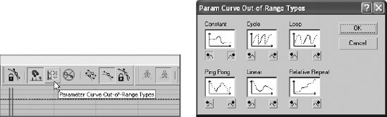
A toolbar runs across the top of the Curve Editor under the menu bar. In that toolbar, click the Parameter Curve Out-of-Range Types button (

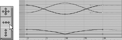
This will open the Param Curve Out-of-Range Types dialog box (Figure 8.20). Select Loop from this window by clicking its thumbnail. The two little boxes beneath it will turn orange. Click OK. To read up on the other Parameter Curve Out-of-Range Types available, see the "Parameter Curve Out-of-Range Types" sidebar later in this chapter.
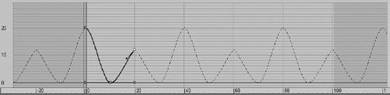
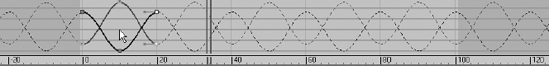
Once you set the curve to Loop, the Curve Editor displays your animation as shown in Figure 8.21. The out-of-range animation is shown in a dashed line. Scrub your animation in a viewport and see how the ball bounces up and down throughout the timeline range.


Reading Animation Curves
As you can see, the Track View-Curve Editor (from here on called just the Curve Editor) gives you control over the animation in a graph setting. Curves allow you to visualize the interpolation of the motion. Understanding what animation curves do in the Curve Editor is critical to getting your animation to look right. Once you are used to reading animation curves, you can judge an object's direction, speed, acceleration, and timing at a mere glance.
The Curve Editor's graph is a representation of an object's parameter, such as position (values shown vertically) over time (time shown horizontally). Every place on the curve represents where the object is; a keyframe does not need to be on the curve. So, the shape of the curve makes a big difference in the motion of the object.
Here is a quick primer on how to read a curve in the Curve Editor.
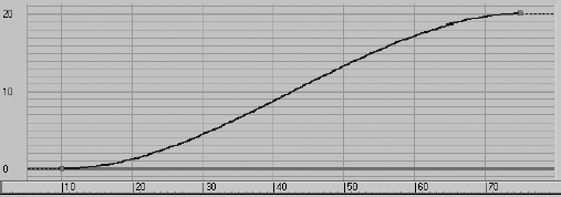
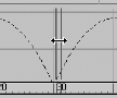
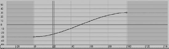
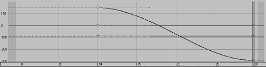
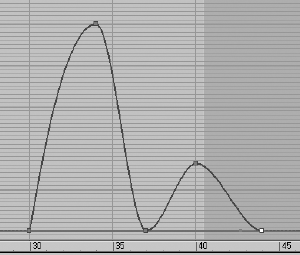
In Figure 8.22, an object's Z Position parameter is being animated. At the beginning, the curve quickly begins to move positively (that is, to the right) in the Z-axis. The object shoots up and comes to an ease-out, where it decelerates to a stop, reaching its top height. The ease-out stop is signified by the curving beginning to flatten out at around frame 70.

PARAMETER CURVE OUT-OF-RANGE TYPES
There are several ways to interpret the curves of an animation when they are out-of-range, meaning when they extend before your first keyframe and beyond your last keyframe. The Parameter Curve Out-of-Range Types is opened through the Curve Editor with this toolbar button (
Constant Used when you do not want any animation out-of-range. This curve type will hold the value of the end and or beginning key of the range for all frames. Constant is the default out-of-range type.
Cycle Used when you need the animation to loop or cycle by repeating the same animation that is within the range. If the first keyframe does not line up with the last keyframe of the curve range, there will be an abrupt "jump" from the last key to the first with every cycle. If the start and end values do not need to match, and that hiccup in the cycle is desired, use Cycle.
Loop Used when you need the animation to loop or cycle smoothly despite any differences in the start and end keyframe values. Loop repeats the same animation in the curve range, but it also interpolates between the last and first keyframes in the range to create a smooth loop in the cycle. Loop's ability to create a smooth loop can only go so far before it acts like a Cycle (e.g., when the key values at the start and end are too disparate).
Ping Pong Used when you want your animation to oscillate back and forth. Ping Pong repeats the same animation in the range, but it plays it front to back and then back to front, and so forth, to alternate the playback, as shown here.
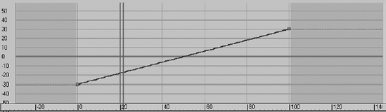
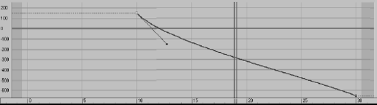
Linear Used when you need your animation to continue at the same velocity as its beginning or end. The animation curve is projected out from the range in a straight line, picking up the trajectory from the shape of the start or end of the curve, as shown here.
Relative Repeat Used when you need your animation to repeat as in a cycle and to continue building on itself as it cycles. Each repetition is offset by the value at the end of the range, as shown here.

You can select any one of these types for either the before or after by clicking one of the smaller boxes below the thumbnails. You can set both the before and after out-of-range type by clicking the thumbnail of the type itself.
You can select any one of these types for either the before or after by clicking one of the smaller boxes below the thumbnails. You can set both the before and after out-of-range type by clicking the thumbnail of the type itself.

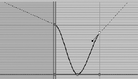
In Figure 8.24, the object eases in and travels to an ease-out where it decelerates starting at around frame 69 to where it slowly stops at frame 75.
Finally, in Link , the object jumps from its Z Position in frame 24, to its new position in frame 25.

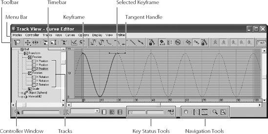
Figure 8.26 shows the Track View-Curve Editor, with notes on its major aspects called out for your information. See the "Track View" section later in this chapter for a more thorough explanation of the UI and toolset for the Track View.
Refining the Animation
Now that you've played back the gross animation of the bounce, how does it look? Not like a ball bouncing, really, but the framework is getting there. Notice how the speed of the ball is consistent. If this were a real ball, it would be dealing with gravity; the ball would speed up as it gets closer to the ground and there would be "hang time" when the ball is in the air on its way up as gravity takes over to pull it back down.
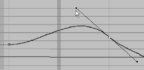
This means you have to edit the movement that happens between the keyframes. This is done by adjusting how the keyframes shape the curve itself using tangents. When you select a keyframe, a handle will appear in the UI, as shown in grayscale in Figure 8.26 and shown up close here.
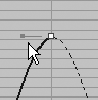
This handle adjusts the tangency of the keyframe to change the curvature of the animation curve, which in turn changes the animation. There are different types of tangents, depending on how you want to edit the motion. By default the Smooth tangent is applied to all new keyframes. This is not what you want for the ball, although it is a perfect default tangent type to have.
Editing Animation Curves
Let's edit some tangencies to better suit your animation. The intent is to speed up the curve as it hits the floor and slow it down as it crests its apex. Instead of opening the Curve Editor through the menu bar, this time you are going to use the shortcut. At the bottom of the interface, click the Mini Curve Editor button shown here.
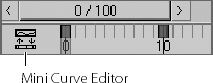
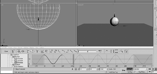
This Mini Curve Editor is almost exactly the same as the one you launch through the main menu bar. A few tools are not included in the Mini Curve Editor toolbar, but you can find them in the menu bar of the Mini Curve Editor. Figure 8.27 shows the Mini Curve Editor open in the 3ds Max UI.
To edit the curves, follow these steps:
Scroll down the List Controller window on the left of the Mini Curve Editor by dragging the Pan tool (the hand cursor) to find the Ball Object/Position XYZ. Click on the Z Position track. This will bring only those curves to the Key window that you want to edit, as you saw in Figure 8.27.
The Z Position curve is blue, as is almost everything relating to the Z-axis. The little gray boxes on the curves are keyframes, as you saw in Figure 8.26. Select the keyframe at frame 10. You may need to scrub the Time Ruler out of the way if you are on frame 10. The key will turn white when selected. Remember, if you need to zoom or pan in the Curve Editor's Key Editing window, you can use the same shortcuts you would use to navigate in the viewports. You will change this key's tangency to make the ball fall faster as it hits and bounces off the ground.
In the Mini Curve Editor toolbar, change the Tangent type for the selected keyframe from the Auto default to Fast by selecting the Fast Tangent icon (

Select the perspective view and play the animation. You can easily correlate how the animation works with the curve's shape as you see the timeline travel through the Mini Curve Editor as the animation plays.

Although the animation has improved, the ball has a distinct lack of weight. It still seems too simple and without any character. In situations such as this, an animator can go wild and try several different things as he or she sees fit. This is where creativity helps hone your animation skills, whether you are new to animation or have been doing it for fifty years.
Animation shows change over time. Good animation conveys the intent, the motivation for that change between the frames.
Squash and Stretch
The concept of squash and stretch has been an animation staple for as long as there has been animation. It is a way to convey the weight of an object by deforming it to react (usually in an exaggerated way) to gravity, impact, and motion.
You can give the ball a lot of flare by adding squash and stretch to give your object some personality. Follow along with these steps:
The Auto Key Animation button should still be active. If it isn't, press N to activate. In the Mini Curve Editor, drag the blue double-line time bar (called the Track Bar Time slider) to frame 10. (See the following graphic.) Click and hold the Scale tool to access the flyout. Choose the Select and Squash tool (

This will scale down in the Z-axis and scale up in the X- and Y-axes to compensate (Figure 8.29).
Move to frame 0. Click and drag up to stretch the ball up about 20 percent (so that the ball's scale in Z is about 120), as shown in Figure 8.30. When you scrub through the animation, you will see that at frame 0 the ball stretched and then the ball squashes and stays squashed for the rest of the time. You'll fix that in the next step. You
You need to copy the Scale key from frame 0 to frame 20 first, and then apply a Loop for the Parameter Out-of-Range Type. Because the Mini Curve Editor is open, it obstructs the timeline; therefore, you should copy the keys in the Mini Curve Editor. You can just as easily do it in the regular Curve Editor in the same way:
In the Mini Curve Editor, scroll in the Controller window until you find the Scale track for the ball. Highlight it to see the keyframes and animation curve. Click and hold the Move Keys tool in the Curve Editor toolbar (

Click and drag a selection marquee around the two keyframes at frame 0 in the Scale track to select. Hold the Shift key, and then click and drag the keyframes at frame 0 to frame 20 (Figure 8.31).
In the Mini Curve Editor's menu bar, select Controller → Out-of-Range Types. Choose Loop, and then click OK. Play the animation. The curves are shown in Figure 8.32.
Setting the Timing
Well, you squashed and stretched the ball, but it still doesn't look right. That is because the ball should not begin to squash too long before it hits the ground. It needs to return to 100 percent scale and stay there for a few frames. Immediately before the ball hits the ground, it can squash into the ground plane to heighten the sense of impact. The following steps are easier to perform in the regular Curve Editor rather than in the Mini Curve Editor. Close the Mini Curve Editor by clicking the Close button.

Open the Curve Editor to fix the timing, and follow these steps as if they were law:
Move the Time slider to frame 8; Auto Key should still be active. In the Curve Editor, in the Controller window, select the ball's Scale track so that only the scale curves appear in the Editing window. In the Curve Editor's toolbar, select the Add Keys button (

Because they are selected, the keys will be white. In the Key Status tools, you will find two text type-in boxes. The box on the left is the frame number, and the box on the right is the selected key(s)' value. Because more than one key with a different value is selected, there is no number in that type-in box. Enter 100 (for 100 percent scale) in the right type-in box, and 3ds Max will enter a value of 100 for the scale in X, Y, and Z for the ball at frame 8, as shown in Figure 8.33.
Move the Time slider to frame 12, and do the same thing in the Curve Editor. These settings are bracketing the Squash so that the Squash happens only a few frames before and a few frames after the ball hitting the ground, as shown in Figure 8.34. Press N to deactivate Auto Key. Save your work.


Once you play back the animation, the ball will begin to look a lot more like a nice cartoonish one, with a little character. Experiment with changing some of the scale amounts to have the ball squish a little more or less, or stretch it more or less to see how that affects the animation. See if it adds a different personality to the ball. If you can master a bouncing ball and evoke all sorts of emotion with your audience, you will be a great animator indeed.
Moving the Ball Forward
Now that you have worked out the bounce, it's time to add movement to the ball so that it moves across the screen as it bounces. Layering animation in this fashion, where you settle on one movement before moving on to another, is common. That's not to say you won't need to go back and forth and make adjustments through the whole process, but it's generally nicer to work out one layer of the animation before adding another. The following steps will show you how:
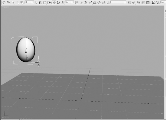
Move the Time slider to frame 0. Select the ball with the Select and Move tool, and move the ball in the Perspective viewport to the left so it is still within the camera's view. That would be about −30 units in the X-axis (Figure 8.35).
Move the Time slider to frame 100. Press N to activate the Auto Key again. Move the ball to the right to about 30 units along the X-axis.
Don't play the animation yet; it isn't going to look right. Go to the Curve Editor, scroll down in the Controller window, and select the X Position track for the ball (Figure 8.36).
When you created the keyframes for the up and down movement of the ball (which was the Z-axis), 3ds Max automatically created keyframes for the X and Y Position tracks, both with essentially no value. To fix it, keep following with these steps:
Select the keyframes on the X Position track at frame 10 and frame 20, and delete them by pressing the Delete key on your keyboard.
Select the Parameter Curves Out-of-Range Types button (

There is still a little problem. Watch the horizontal movement. The ball is slow at the beginning, speeds up in the middle, and then slows again at the end. It eases in and eases out, as you can see in the curve in Figure 8.37. This is caused by the default tangent, which automatically adds a slowdown as the object goes in and out of the keyframe. In the Curve Editor, select both keys for the X Position and click on the Linear Tangent (

Figure 8.38 shows the proper curve.

Adding a Roll
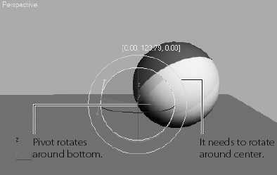
You need to add some rotation, but there are several problems with this. One, you moved the pivot point to the bottom of the ball in the very first step of the exercise. You did that so the squashing would work correctly, that is at the point of contact with the ground. If you were to rotate the ball with the pivot at the bottom, it would look like Figure 8.39.
Using the XForm Modifier
You need a pivot point at the center of the ball, but you can't just move the existing pivot from the bottom to the middle—it would throw off all the squash and stretch animation.Unfortunately, an object can have only one pivot point. To solve the issue, you are going to use a modifier called XForm. This modifier has many uses. You're going to use it to add another pivot to the ball in the following steps:
At this point, double-check that AutoKey is deactivated. The button is red when it is active.
Select the ball. From the main menu bar, select Modifiers → Parametric Deformers → XForm. You may also select it from the Modifier List from the Modify panel. XForm will be added to the ball in the Modifier Stack, and an orange bounding box will appear over the ball in the viewport. XForm has no parameters, but it does have sub-objects, as you can see here.

Expand the Modifier Stack by clicking the black box with the plus sign next to Xform. Then click Center. You will use the Align tool to center the XForm's center point on the ball in the next step.
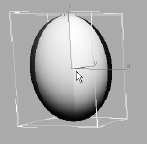
Click the Align tool, and then click on the ball. In the dialog box, make sure the check box for the X, Y, and Z are checked, which means those axes are active. Now click Center under Target Object, and then press OK. The XForm's center will move, as shown here.
Now to be clear, this isn't a pivot point. This is the center point on the XForm modifier. If you go to the Modifier Stack and click on the Sphere, the pivot point will still be at the bottom, as shown here.
Now, the XForm modifier allows the ball to rotate, without Squash and Stretch getting in the way. By separating the rotation animation for the ball's roll into the modifier, the animation on the sphere object is preserved.

Animating the XForm Modifier
To add the ball's roll to the XForm modifier, follow along with these illuminating and incredibly insightful steps:
Turn on Auto Key and select the Select and Rotate tool.
In the Modifier Stack, click on Gizmo for the sub-object of XForm. This is a very important step because it tells the Modifier to use the XForm's center instead of using the pivot point of the ball.
Move the Time slider to frame 100 and rotate the Ball 360 degrees on the Y-axis (you can use Angle Snap to make it easier to rotate exactly 360 degrees). Click on the XForm to deactivate the sub-object mode. Play the animation.
The ball should be a rubbery cartoon ball at this point in the animation. Just for practice, let's say you need to go back and edit the keyframes because you rotated in the wrong direction and the ball's rotation is going backward. Fixing this issue requires you to go back into the Curve Editor as follows:
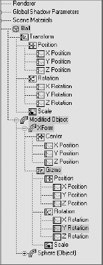
Open the Curve Editor (mini or regular). Scroll down in the Controller window until you see the Ball tracks. Below the Ball's Transform track is a new track called Modified Object. Expand the track by clicking on the plus sign in the circle next to the name. Go to the gizmo and select Y Rotation Track (Figure 8.40).
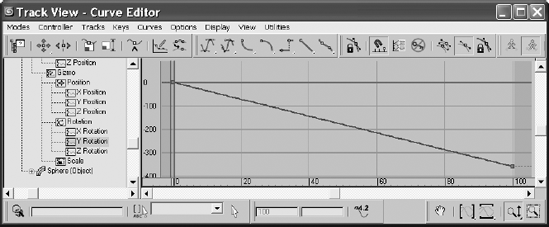
You will see the Function curve in the Edit Key work area. You want the keyframe at frame 0 to have the value 0 and the keyframe at frame 100 to be 360 degrees. Select both keyframes and change the Tangent to Linear, as shown in Figure 8.41.
Close the Curve Editor and play the animation. Play the Bounce Ball.mov QuickTime movie file located in the RenderOutput folder of the Bouncing Ball project on your hard drive (or on the CD) to see a render of the animation. You can also load the Animation_ Ball_02.max scene file from the BouncingBall project folder on your hard drive (or on the CD) to check your work.
Bouncing Ball Summary
Working with the bouncing ball gave you quite a bit of experience with the 3ds Max's animation toolset. There are several ways to animate a bouncing ball in 3ds Max. It is definitely a good idea to try this exercise a few times at first, and then to come back to it later—after you have learned other 3ds Max techniques.
Note
If you are interested in seeing the differences in workflow between 3ds Max and Maya, you can see how to animate the bouncing ball with a similar ball exercise in Introducing Maya 2008: 3d for Beginners
Track View
As you have already seen, the Track View-Curve Editor is a powerful tool for creating and editing your animation scenes. In this section, the user interface for the Track View is laid out and explained as a brief reference for you. Figure 8.42 shows the Track View-Curve Editor.

The Curve Editor window can be a bit daunting at first. Now that you've had some experience with it in this chapter, it should seem pretty straightforward. The left side of the window (called the Controller window) displays the objects in the scene in an outline format. These objects have subheadings called tracks under them when they are animated. Each track will define animation on one axis of movement or rotation or scale, or one parameter that is keyframed. When you click on a track, its animation information will display in the graph area on the right. In the Curve Editor, you can access the curves and keyframes to edit the animation. In the Dope Sheet version of the Track View, you can access keys in a different manner, as discussed in the next chapter.
You can switch between the Curve Editor and the Dope Sheet by selecting the desired window in the Modes menu in the main menu bar. Most of the tools discussed here are also accessible through the menu bar and the toolbar. The toolbar is divided into function sets.
Key Tools Toolbar
The following table lists the tools used in editing keys in the Curve Editor window. You used a few of these tools in the Bouncing Ball animation.
As you saw with the bouncing ball, changing the tangency on a few keys can dramatically alter the look of your animation. By default, new keys are set to Auto Tangents, which generally keep the curve smooth. 3ds Max sets an appropriate tangency automatically; however, you can easily change the tangency by manually moving the handles on the keyframes. Once you select an Auto Tangent's handle, 3ds Max will automatically shift the handle to a custom handle, allowing you to move it. The following table lists the icons for the tangency tools.
I C O N | NAME | F U N C T I O N |
|---|---|---|
Set Tangents to Auto | This rollout icon boasts three tools for controlling Auto tangents. The top icon sets both handles to Auto, the middle sets the In tangent, and the bottom icon sets the Out tangent to Auto. | |
Set Tangents to Custom | Custom tangents allow you to move the handles to form your own curvature. If you hold the Shift key as you drag a tangent handle, it will break continuity with the other handle, allowing you to have a different In tangency than Out tangency. | |
Set Tangents to Fast | Sets the tangent to accelerate in or out of a keyframe quickly, or both. | |
Set Tangents to Slow | Sets the tangent to go slowly into or out of the keyframe, or both. | |
Set Tangents to Step | Sets the tangent to "jump" from one value to the next in a single frame. The animation will be frozen until the next keyframe when it will jerk to that position or value. | |
Set Tangents to Linear | Sets the tangency to a straight linear progression into or out of the keyframe, or both. | |
Set Tangents to Smooth | Attempts to keep the curve smooth across all values to achieve a more realistic motion in many cases. |
The Curves tools act on the animation curves themselves, allowing you to easily make changes to an animated track. You will run into some of these tools as you become more experienced with Max. Don't worry about memorizing all these functions.
I C O N | NAME | F U N C T I O N |
|---|---|---|
Lock Selection | Locks the current selection so you don't accidentally select something else. | |
Snap Frames | Snaps keys to frames when you move them. When off, you can move keys to sub-frames (i.e., in-between frames). | |
Parameter Out-of-Range Curves | Allows you to set the behavior of your animation before and beyond the keyframed range. | |
Show Keyable Icons | Toggles an icon to tell you whether a track is keyable or not. Red is keyable; black is not. | |
Show Tangents | Toggles the display of tangent handles on individual curves. | |
Show All Tangents | Toggles the display of tangent handles on all curves in the graph. | |
Lock Tangents | Locks a selection of tangent handles so you can adjust them all at once. When off, however, you only have access to one tangent handle at a time. |
These new Curve Editor Biped tools make the process of using the Curve Editor for biped animation much more streamlined than before. Biped tools will be covered in the next chapter. The following table lists the icons and their names for your reference. The Biped toolbar is visible only if you have a biped in your scene.
I C O N | NAME |
|---|---|
Show Biped Position Curves | |
Show Biped Rotation Curves | |
Show Biped X Curves | |
Show Biped Y Curves | |
Show Biped Z Curves |
These tools are for Track View navigation. Tools such as Pan, Zoom, and Zoom Region work the same as in the Viewport Navigation tools. Some of the tools are designed specifically for the Track View. A few often-used icons are listed in the following table:
I C O N | NAME | F U N C T I O N |
|---|---|---|
Pan | Use this tool to drag the key window. You can also use the middle mouse button. | |
Zoom Horizontal Extents | Adjusts the display so that the entire active time segment is shown. | |
Zoom Value Extents | Adjusts the display so that the full heights of the curves are visible. | |
Zoom | Zooms both time and value proportionally together. This is a rollout with two other Zoom options nested. | |
Zoom Region | Lets you drag a region to scale the display to fit. |
This exercise will give you more experience animating in 3ds Max. In it, you'll animate a knife being thrown at a target. You will edit more in the Curve Editor and be introduced to the concept of anticipation in animation, as well as momentum and secondary movement.
Blocking Out the Animation
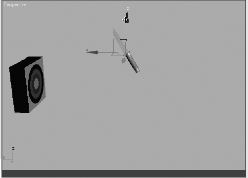
To begin this exercise, open the Animation_Knife_00.max file in the Knife project and follow along here:
Move the Time slider to frame 30 and activate the Auto Key button.
Move the knife to the target object, as shown in Figure 8.43.
Move the Time slider to frame 15, where the knife is halfway between its start and the target, and move the knife slightly up in the Z-axis, so that the knife moves with a slight arc (Figure 8.44).
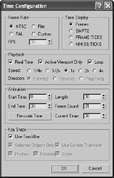
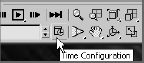
For now, change the frame range in the Time slider so you're working between frame 0 and frame 30. Click the Time Configuration button (

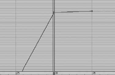
Scrub your animation, and you should see the knife move with a slight ease-in and ease-out toward the target with a slight arc up in the middle. You want the position of the knife to start at frame 10, so open the Curve Editor and scroll down in the Controller window until you see the three X, Y, Z Position tracks for the knife. Hold the Ctrl key and select all three tracks to display their curves (Figure 8.46).
Drag a selection marquee around the keyframe at frame 0 (Figure 8.47). In the Curve Editor toolbar, select and hold the Move tool (

This will compact the curve, as shown previously, so you will need to move the keys at frame 15 to the new middle, frame 20 (Figure 8.48).


That's it for the gross animation or blocking of the shot. Did you have fun?
Trajectories
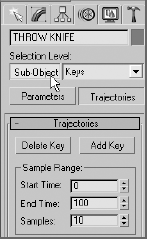
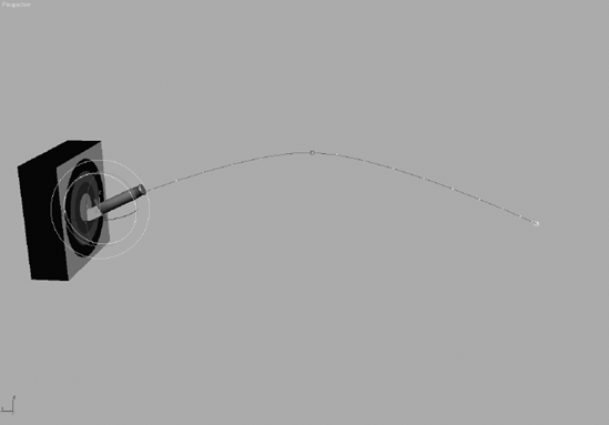
When it comes to animation, it is very helpful to be able to see the path your object is taking over time. These paths are known as trajectories in Max. The easiest way to see the trajectories is to select the knife object, go to the Motion panel, and click Trajectories, as shown in Figure 8.49. Your viewports will display a red curve to show you the path of the knife's motion as it arcs toward the target, as shown in Figure 8.50.
The trajectory will remain displayed until a moving object is selected. The large hollow square points on the trajectory curve represent the keyframes set on the knife so far. Let's adjust the height of the arc using the trajectory curve. Turn on the Sub-Object button at the top of the Motion panel (Figure 8.51).


Keys are your only sub-object choice in the pull-down menu to the right of the button. Select the middle keyframe and move it up or down to suit your tastes, as shown in Figure 8.52. Once you settle on a nice arc for the path of the knife, turn off the Trajectories button.
As you can imagine, the Trajectories panel can be useful in many situations. It not only gives you a view of your object's path, but it also allows you to edit that path easily and in a visual context, which can be so important.
Adding Rotation
The next step is to add a bit of rotation to the knife. As an animator, you need to research and gather as much information about your subject matter as you can. Throwing knives is usually a bad idea, but you can throw something else—ideally something that is shaped and weighted like a knife—at a target (the inanimate kind) to see how to animate your knife. Almost invariably, you'll find that the object will have to rotate once or twice before it hits its target. To add rotation to your CG knife, follow these steps:
Move to frame 30, and press E for the Select and Rotate tool. Auto Key should still be active. Rotate in the Y-axis 443 degrees, as shown in Figure 8.53.
Open the Curve Editor, scroll down to find the X, Y, and Z Rotation tracks, and select them. Use the Horizontal Move tool to shift the keyframes at 0 to frame 10. Press N to deactivate the Auto Key. Figure 8.54 shows the Curve Editor graph for the knife.
Play the animation, and you will see that the knife's position and rotation eases in and eases out. A real knife would not ease its rotations or movement. Its speed would be roughly consistent throughout the animation.
Go back to the Curve Editor, select the X Position track, and then select all the keyframes and switch the Tangent to Linear. Now select the Z Position track; you'll need to finesse this one a bit more than the X Position. You are going to use the handles on the tangents that appear when you select a keyframe. These handles can be adjusted; just center your cursor over the end and click and drag. Figure 8.55 illustrates how you want the Z Position animation curve to look. This will give the trajectory a nice arc and a good speed of travel.
Now it is time to edit the Rotation keys. In the Curve Editor scroll to find the X, Y, and Z Rotation tracks. The first thing you can do is add a bit of drama to the knife to make the action more exciting. To this end, you can say that the rotation on the knife is too slow. Select the X Rotation track and select its keyframe at frame 30. In the Key Stats, change the value to −52. The higher the value, the faster the knife will rotate. This will add one full revolution to the animation and some more excitement to the action.
Adjust the tangent handles to resemble the curve shown in Figure 8.56. The knife will speed up just a little bit as it leaves the first rotate keyframe. The speed will be even as it goes into the last keyframe.


With just a little bit of fast rotation as the knife leaves frame 10, you give the animation more spice. A little change in the curve can make a big difference in an animation—every little bit counts. The knife should now have a slightly weightier look than before when it rotated with an ease-in and ease-out.
Adding Anticipation
Instead of making the knife just fly through the air toward the target, you should animate it to move back first to create anticipation, as if an invisible hand holding the knife pulled back just before throwing it to get more strength in the throw. This anticipation, although it's a small detail, can add a level of nuance to the animation that enhances the total effect. Follow these steps:
Move the Time slider to frame 0. Go to the Curve Editor, scroll the Controller window, and select X Rotation track for the knife. In the Curve Editor toolbar, click the Add Keys button (

Select the Move tool and select the key at frame 10. In the Key Stats type-in, change the value of that key to 240. If you play back the animation, it will look weird. The knife will cock back really fast and spin a bit. This is due to the big hump between frames 0 and 10.
Keep the tangent at frame 0 set to the default, but change the tangent on the key at frame 10 to Linear. Play back the animation. You'll have a slight bit of anticipation, but the spice will be lost and the knife will look less active and too mechanical.
To regain the weight you had in the knife, press Ctrl+Z to undo your change to the tangency on frame 10 and set it back to what you had (just like Figure 8.57). You may have to undo more than once. Now, select the Vertical Move tool and select the In tangent for keyframe 0. This is the tangent handle on the left of the key, as shown in Figure 8.58.
Note
It's very common to try something in the course of your work, and rely on Undo to get back to the starting point. You can sometimes expect to Undo several times when you find yourself at a dead end.
Press Shift and drag the tangent handle down to create a curve that is similar to the one shown in Figure 8.59. By pressing Shift as you dragged the tangent handle, you broke the continuity between the In and Out handles, so that only the In handle was affected. Play back the animation. It should look much better now.

Remember, the smallest tweaks in the Curve Editor can have a huge positive or negative impact on your animation.

Figure 8.59. To create a believable anticipation for the knife throw, set your curve to resemble this one.
Follow-Through
The knife needs more weight. A great way to show that in animation is by adding followthrough. This is part of the animation concept of secondary movement that was mentioned in Chapter 1. The follow-through for the knife would be having the knife sink into the target a little bit and push back the target as it transfers momentum to the target. For more on momentum, see the sidebar later in this chapter.
Knife Follow-Through
To add follow-through to your animation, follow these steps:
You want to sink the knife into the target after it hits. Select the Time Configuration button (shown in the following graphic), and change the End Time to 40 to add 10 frames to your frame range. This will not affect the animation; it will merely append 10 frames to the current frame range.
Select the knife and go to frame 30, where it hits the target. In the Curve Editor, select the X Position of the knife. Add a keyframe with the Add Keys tool at frame 35.
Note the value of the key in the type-in boxes at the bottom of the Curve Editor window (not the type-in boxes at the bottom of the main UI). In this case, the value in this scene is about −231. You will want to set the value for this key at frame 35 to about −224 to sink it farther into the target. If your values are different, adjust accordingly so you don't add too much movement. Also make sure the movement flows into the target and not back out of the target as if the knife were bouncing out.
Keep the tangent for this new key set to Auto. With these relative values, scrub the animation between frames 30 and 35. You should see the knife's slight move into the target. The end of your curve should look like the curve in Figure 8.60.
You still need to add a little bit of follow-through to the rotation of the knife to make it sink into the target better. In the Curve Editor, select the X Rotation to display its curve. Add a key to the curve at frame 35. The value of the key at frame 30 should already be about −652. Set the value of the keyframe at frame 35 to be about −655 (Figure 8.61). Keep the tangent set at Auto.
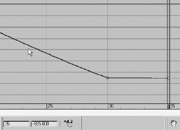
Be careful about how much the knife sinks into the target. Although it is important to show the weight of the knife, it is also important to show the weight of the target; you do not want the target to look too soft. Make sure your keys at frame 35 for the X Position and X Rotation are not too much.
Transferring Momentum to the Target
To make the momentum work even better for the Knife animation, you will have to push back the target as the knife hits it. The trouble is, if you animate the target moving back, the knife will float in the air. You have to animate the knife with the target. However, animating them separately in the hopes they will match up will frustrate you and will more than likely look bad.
If you think that hierarchy has to be involved here, you are absolutely right. Basically, the knife will have to be linked to the target so that when the target is animated, the knife will follow precisely, because it is stuck in the target.
This won't mess up the animation of the knife. Because the knife will be the child in the hierarchy and can have its own animation separate from the target, you can link it after you are finished with the knife animation. Just follow these steps:
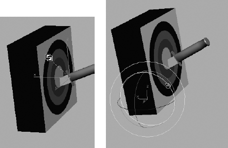
Go to frame 30, where the knife impacts. Select the Select and Link tool. Select the knife and drag it to the target as shown in Figure 8.62. Nothing should change until you animate the target object.
Move the Time slider to frame 34 and press N to activate the Auto Key tool. With the Select and Rotate tool, select the target object and rotate it back about 5 degrees as shown in the second image in Figure 8.62. The pivot of the target has already been placed properly, at the bottom back edge.
Go to the Curve Editor, scroll to find the Y Rotation track for the target object, select the keyframe at frame 0, and move it to frame 30. Then hold the Shift key, and click and drag the keyframe (which will make a copy of it) to frame 37. Your curve should resemble the curve in Figure 8.63.
Change the Tangent at frame 0 to Fast and leave the other keyframe tangents alone.
Add a little wobble to the target to make the animation even more interesting. This can be done very easily in the Curve Editor. Select the Y Rotation of the target to display just that curve. Use Add Key to add two keyframes at frames 40 and 44. Using the Vertical Move tool, give the key at frame 40 a value of about 1.7. Your curve should resemble the one in Figure 8.64.
Finally, add a little slide to the target. Get the Select and Move tool, move the Time slider to frame 37, and move the target just a bit along the X-axis. Go to the Curve Editor, scroll to the X Position of the target object, select the keyframe at frame 0, and move it to frame 30 so the move starts when the knife hits the target. Change the tangent for frame 30 to Fast and leave the other tangent at Auto.

Done! Play back your animation. Experiment and change some of the final timings of the target's reaction to the impact, as well as some of the values, to see how small changes can make big differences in how the weights of the knife and target look to the viewer.
Note
A similar exercise where you throw an ax teaches you much the same animation practice in Maya in Introducing Maya 2008: 3d for Beginners, if you are curious about how 3ds Max and Maya animate similar scenes.
In this, the first of two chapters on animation in this book, you learned the basics of creating and editing animation. You learned how to fix hierarchy problems in animation and how to use dummy objects to help you animate properly. You bounced a ball to learn timing issues and how to edit animation curves through the Curve Editor. You then learned the ins and outs of the Track Editor-Curve Editor before moving on to a thrown knife to learn about trajectories and the concepts behind using secondary movement to help give your animation weight.
Animation can be a lot of fun, but it is also tedious and sometimes aggravating. A lot of time, patience, and practice are required to become good at animation. It all boils down to how the animation makes you think. Is there enough weight to the subjects in the animation? Do the movements make sense? How does nuance enhance the animation? These are all questions you will begin to discover for yourself. This chapter merely introduced you to how to make things move in 3ds Max. It gave you some of the basics of animation techniques to help you develop your eye for motion. Don't stop here. Go back into the chapter and redo some of the exercises. Try different variations on the same themes. Keep working.