
This chapter gets your engine revving right away. It begins with an overview of the user interface (UI) and starts you off with an exercise that will expose you to quite a few Autodesk 3ds Max workflows and practices. The goal of the chapter is to put some concepts from the previous chapter into production so you can get going quickly.
Topics in this chapter include:
Getting Around in 3ds Max
Project and File Management Workflow
The 3ds Max Interface
Jumping Headlong into Animation
Setting Up the Hierarchy
Ready, Set, Animate
At this point, it's important not to get caught up in the details of this great machine. Don't worry about the steps, buttons, menus, switches, and levers; just allow yourself to become comfortable with the tools that you use to create your artwork. Creating art is never about which button to press; it's about what to create. Always remember that, and your studies will be a great deal more successful.
Jumping straight into an exercise without knowing how to get around the interface might seem a little weird. However, you'll find everything you ever wanted to know, and then some, in Chapter 3, "The 3ds Max Interface." Learning is an experimental art, and there's no better way to learn than to start experimenting as soon as you can. The overall goal of this chapter is to expose you to the UI and show you how to get some things done in Max. Then you can proceed to the next chapter for a debriefing. (If you prefer, you can skip ahead to Chapter 3, get a tour of the UI, and then come back to this chapter for your first experience.)
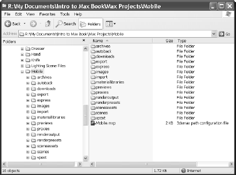
Autodesk 3ds Max provides several subfolders automatically grouped into projects for you. Different kinds of files are saved in categorized folders under the Project folder. For example, scene files are saved in a Scenes folder and rendered images are saved in a Render Output folder in the Project folder. The projects are set up according to what types of files you are working on, so everything is neat and organized from the get-go. 3ds Max will automatically create this folder structure for you once you create a new project, and its default settings will keep the files organized in that manner.
The conventions followed in this book and on the accompanying CD will follow this project-based system so that you can grow accustomed to it and make it a part of your own workflow. File organization is extremely important for professional work. If you do a lot of CG for fun or profit, it pays to be organized.
The exercises in this book are organized into specific projects, such as the one you will tackle in this chapter, Mobile. The Mobile project will be on your hard drive, and the folders for your scene files and rendered images will be in it. Once you copy the appropriate projects to your hard drive, you can tell 3ds Max which project to work on by choosing File → Set Project Folder. This will send the current project to that project folder. For example, when you save your scene, Max will automatically take you to the Scenes folder of the current project.
Before we begin any project, we'll briefly explain the naming conventions and suggest a folder structure. Using these naming conventions and structures is a good habit to develop.
Naming Conventions
Every studio and professional production company worth its salt has an established naming convention for its files and folders. This is a documented procedure that dictates how to name files and (usually) where to store them. Most organizations have different conventions, but the point is to have a convention and stick to it.
Students, in particular, tend to forgo any semblance of organization in their file-naming procedures. A common mistake is to save files to the local disk on the school computer, only to have the files erased by the support teams during the school's weekly purge. Designating a specific place on your PC or server for all your project files is important.
In addition to finding a suitable place to store your files, you need to name the files following some sort of convention. Your files will not only look neat when you're browsing, but they'll make sense months later when you try to figure out where that finished scene file is that you need. Typically, you should name a scene file with a project name or an abbreviation of such, then a brief description of what the file is, and a version number.
For example, if you are working on a project about a castle, begin by setting a new project called Castle. Choose File → Set Project Folder. On your hard drive, click the Make New Folder button (Figure 2.1) to create a folder named Castle. 3ds Max will automatically create the project and its folders.
Once you save a scene, one of your scene filenames should look like this: Castle_GateModel_v05.max. This tells you right away it's a scene from your Castle project, and that it is a model of the gate. The version number tells you that it's the fifth iteration of the model and possibly the most recent version. Following a naming convention will save you oodles of time and aggravation.

Version Up!
The naming convention just mentioned used a version number appended to the end of the filename. After you've spent a significant amount of time working on your scene, or after you've made a major change or big breakthrough in your work, you will want to version up. This means you save your file using the same name, but you increase the version number by one to tell yourself, or your colleagues, that there was a big change since the last version. Version numbers are also useful for keeping track of your progress.
Version numbers can also save your hide. If you start down a path on your scene, but discover after hours of work (and saving your work as you go along, versioning up as you went) that this was indeed the wrong way to go, you can simply close the scene and open one of the previous versions that you created before you started going in the wrong direction. This happens a lot more than you might think.
Disk space is cheap and scene files, even huge ones, aren't all that big in the face of the hundreds of gigabytes you can buy for less than $100. Keep a notebook and a pen next to your workstation so that you can take notes on your progress and record exactly what you did during your work sessions. Professionals do this regularly. They can't afford to waste time trying to figure out what file they should load to access a particular chunk of work.
The Basic Project Structure Used in This Book
Each exercise in this book will be its own 3ds Max project. Pick a place on your hard drive and start there. Create a folder called Max Projects on your C: drive (you can create one anywhere you want, including your My Documents folder). Place all of your projects in this folder. This will make it easy to find your files and back them up to CD or tape.
Let's create the first project we'll be working on, Mobile. Select File → Set Project Folder, navigate to your Max Projects folder (or My Documents folder), and then click Make New Folder. Name the folder Mobile. 3ds Max will create the subfolders for the project, as shown in Figure 2.2.
That's pretty much it. Having a naming convention is easy; sticking to it is not, especially when you're first starting out. Make sure you stick to it.
Saving Your Scenes in Max
Save your scene frequently to protect yourself from mistakes and from losing your work. Choosing File → Save updates the current scene by overwriting the last save of the scene. If no scene was previously saved, this command opens the Save File As dialog box. Using it, you can select where to save the scene and enter your scene's name. If you are working on a scene already, I recommend using Save As so you do not accidentally overwrite your current work. You can also use an incremental save function discussed shortly.
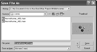
To "version up," you can save by using File → Save As and manually changing the version number appended to the end of the filename. Max also lets you do this automatically by using an increment feature in the Save As dialog box. Simply name your scene file and click the Increment button (the + icon) to the right of the filename text (Figure 2.3).
Clicking the Increment button will append the filename with 01, then 02, then 03, and so on as you keep saving your work using Save As and the Increment button. In the previous example, the scene's base filename was SceneName_v. Clicking the Increment button added the two-digit version number after the _v. Adding the _v is a personal preference, of course, but it keeps with the naming convention set up in this book. It looks nicer, and you can easily determine the version number for your file by reading the number after the _v.
Here is a brief rundown of what you need to know about the UI and how to navigate in Max's 3D space. We will cover the interface in more detail in the next chapter, so feel free to jump back and forth if you need to know more about the UI.
The menu bar running across the top of the UI gives you access to a ton of commands— from basic file operations, such as Save, to advanced tools you may need for a scene. Immediately below the main menu bar is the main toolbar. It contains several icons for functions such as Undo and the three Transform functions (Move, Rotate, and Scale). You will use some of these icons for the Mobile exercise. They are described more fully in Chapter 3.
The Command Panel
The Command panel is a vertical column or panel on the right side of the Max UI. It is segmented into tabs, as shown in Figure 2.4. Each tab displays the buttons and icons for a particular part of your workflow, such as creating objects, modifying objects, and animating objects. In each tab, the functions are grouped under headings that can be expanded or collapsed by clicking on the heading title. A plus next to the heading name means that you can expand the heading's view; a minus means that you can collapse the heading to save space.
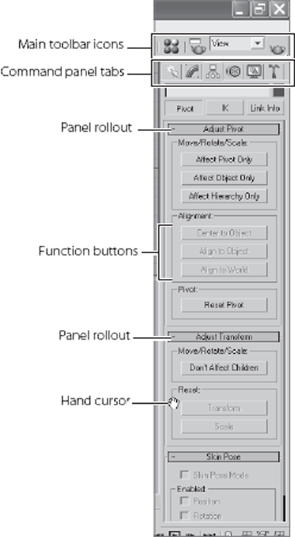
Figure 2.4. The Command panel is segmented into heaings called rollouts that group similar functions and icons.
If you mouse over the Command panel, the arrow pointer will change to a hand pointer, as shown in Figure 2.4, when it is not on a button or icon. While the pointer is a hand, you can click and drag to move the current panel up and down in the Command panel to see more functions in that space. You can also click on the far right side of the panel to scroll up and down if you don't want to use the hand.
As shown here, the viewport controls, which contain icons for various options for the 3D world windows (called viewports), are in the lower-right corner of the UI. These functions allow you to navigate the windows and their 3D space (

Viewports
You'll be doing most of your work in the viewports. These windows represent 3D space using a system based on Cartesian coordinates. That is a fancy way of saying "space in X-, Y-, and Z-axes." All CG programs, including 3ds Max, are based on this coordinate system.
You can visualize X as left–right, Y as up–down, and Z as in–out (into and out of the screen). The coordinates are expressed as a set of three numbers such as (0, 3,−7). These coordinates represent a point that is at 0 in the X-axis, three units up in the Y-axis, and seven units back in the Z-axis.
Four-Viewport Layout
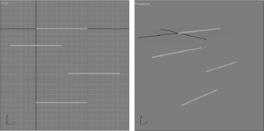
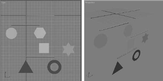
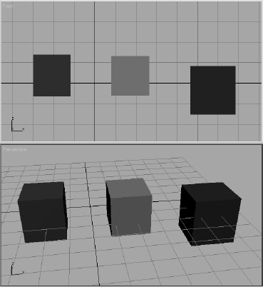
3ds Max's viewports are the windows into your scene (Figure 2.5). By default, there are four main views: Front, Top, Left, and Perspective. The first three: Front, Top, and Left, are called Orthographic (2D) views. They are also referred to as modeling windows. These windows are good for expressing exact dimensions and size relationships, so they are a good tool for sizing up your scene objects and fine-tuning their layout.
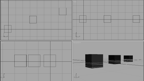
The Perspective viewport displays objects in 3D space using a simulation of perspective. Notice in Figure 2.5 how the distant cubes seem to get smaller in the Perspective view. In actuality, they are the same size, as you can see in the Orthographic views. The Perspective view gives you the best representation of what your output will be.
To select a viewport, click in a blank part of the viewport (not on an object). If you do have something selected, it will be deselected when you click in the blank space. You can also right-click anywhere in an inactive viewport to activate it. When active, the view will have a yellow highlight around it. If you right-click in an already active viewport, you will get a pop-up context menu called the Quad menu. You can use this shortcut menu to access some basic commands for a faster workflow. We will cover this and other shortcut menus in the next chapter.
Display of Objects and Axes in a Viewport
Viewports can display your scene objects in a few different ways. If you right-click the viewport's name, the right-click Viewport menu will appear (Figure 2.6). The most common view modes are Wireframe mode and Smooth + Highlights mode. Wireframe mode displays the outlines of the object. It is the fastest to use because it requires less computation on your video card. The Smooth + Highlight mode is a shaded view where the objects in the scene appear solid. You will get the chance to experiment with different display modes in the upcoming Mobile exercise.
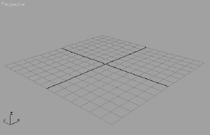
Each viewport displays a ground plane grid (as shown in the Perspective viewport), called the Home Grid (Figure 2.7). This is the basic 3D space reference system. It's defined by three fixed planes on the coordinate axes (X, Y, Z). The center of all three axes is called the origin. This is where the coordinates are (0, 0, 0). The Home Grid is visible in 3ds Max's default settings when you start the software, but it can be turned off in the right-click Viewport menu. You can also toggle the grid by pressing G.
The Perspective viewport has a red, green, and blue axis marker in which the X-axis is red, the Y-axis is green, and the Z-axis is blue. Max uses this red, green, and blue color scheme to represent the X-, Y-, and Z-axes throughout the interface.
Note
Most 3D packages use red, green, and blue to represent X-, Y-, and Z-axes, respectively. It's not just a Max thing.
Selecting Objects in a Viewport
Selecting objects in a viewport is as easy as clicking them. If the object is displayed in Wireframe mode, its wireframe will turn white while it is selected. If the object is displayed in a Shaded mode, a white bracket will appear around the object as shown in Figure 2.8.

To select multiple objects, hold the Ctrl key down as you click additional objects to add to your selection. If you Ctrl+click an active object, you will deselect it. You can clear all of your active selections by clicking anywhere an empty area of the viewport.
Note
The Alt key can also be used to subtract objects from a selection set.
Changing/Maximizing the Viewports
To change the view in any given viewport—for example, to go from a Perspective view to a Front view—right-click the current viewport's name. From the context menu, select View and then select the view you want to have in this viewport, as shown in Figure 2.9.

A faster way to change viewports is by using keyboard shortcuts. To switch from one view to another, press the appropriate key on the keyboard as shown in the following table:
V I E W P O R T | K E Y B O A R D S H O R T C U T |
|---|---|
Top View | T |
Bottom View | B |
Front View | F |
Left View | L |
Camera View | C |
Perspective View | P |
If you want to have a larger view of the active viewport than is provided by the default four-viewport layout, press the Maximize Viewport Toggle icon (
Viewport Navigation
To work effectively, you will need to navigate in 3D space. Max allows you to move around its viewports either by using key/mouse combinations, which are highly preferable, or by using the viewport controls found in the lower-right corner of the Max UI. A full explanation of the viewport controls is in the next chapter. However, to navigate within the views, you should become familiar with the key/mouse combinations now.
Open a new, empty scene in Max. Experiment with the following controls to get a feel for moving around in 3D space. If you are new to 3D, this may seem odd at first, but it will become easier as you gain experience and should become second nature in no time. If you are coming to 3ds Max from another 3D package, such as Maya, you will notice several things that will take a little getting used to, but you will also notice similarities. With time and practice, you should be able to hop back and forth between packages with little confusion.
Pan Panning a viewport will slide the view around the screen. Using the middle mouse button (abbreviated in the remainder of this text as MM), click in the viewport and drag the mouse pointer to move the view.
Zoom Zooming will move your view in closer or farther away from your objects. To zoom, press Ctrl+Alt and MM+click in your viewport, and then drag the mouse up or down to zoom in or out, respectively. It is more common to use the scroll wheel to zoom, however.
Note
Zooming is sometimes called dollying in other packages; Max also has a dolly function, but it is active only when you are in a Camera viewport. Max differentiates between Camera viewports and Perspective viewports, unlike other packages).
Arc Rotate Arc rotate will rotate your view around your objects. To arc rotate, press Alt and MM+click and drag in the viewport. By default, Max will rotate (or tumble, as it's called in some other CG programs) about the center of the viewport to change your perspective.
Note
The arc rotate move is used primarily in the Perspective views and is not used in the Orthographic views. If you accidentally arc rotate in one of the Orthographic views, you will be given a new User view. This view will be similar to a perspective. However, it will remain orthographic, meaning that there will be no vanishing point or perspective shift in the view; it is not a real Camera view. You can reset the view back to your straight Orthogonal view by right-clicking the User viewport's name and selecting your original view.
Let's get busy and dive right into 3ds Max and create an animation. You may not understand the reasons for all the things you're about to do, but you will get a quick trial by fire by getting into the program and following these steps, which will guide you through some of the basic workflows for Max.
For your first experience, we will create a simple mobile. This example will teach you the basics of object creation, hierarchies, setting keyframes to create animation, and general workflow.
Plan of Attack for Making Objects
It's always a good idea to go into something with a goal in mind. Knowing, even roughly, where you are headed will make things much easier. In production work, setting down a plan and having clear goals for your animation is very important. Without a good idea of where you need to go, you'll end up floundering and losing out on the whole experience. With that in mind, our goal in this chapter is to create a finished mobile, like the ones that hang over baby cribs. Because this is our first foray into Max, let's start with a simple object, so we won't be bogged down with the specifics of creating masterful models. Instead, we'll use simple objects that are easily created in Max.
Hierarchies
Once we model the mobile, we'll set up the pieces for animation. We will do this by creating proper hierarchies within the scene. The concept of hierarchy is a common feature in almost all CG packages. The hierarchy in a CG scene deals with how objects are arranged in a scene in relation to each other. Parents in a hierarchy lead children; where a parent goes, the children follow. When you translate (move) or rotate or scale a parent object, its children will move, turn, or scale along with it.
However, children retain the ability to move individually under their parent's supervision. The Mobile exercise is a perfect way to demonstrate the idea of hierarchies. Take a look at Figure 2.10, which displays the completed mobile. The top bar (the parent), from which the other bars hang, rotates and takes the lower bars (its children) with it. In this exercise, we will also animate the lower bars to rotate individually, just as a real mobile would.

The dangling shapes on the lower bars are the children of their respective bars. Those lower bars are children of the bars above them, and so on up to the top bar that controls the rotation of the entire mobile. Once you begin working on it, it will make more sense. As you can see now, hierarchy plays an important part in animation.
Don't get hung up on all the steps and what they mean. This is a quick dip in the pond to get your feet wet. In the next chapters, we will explain everything you did here.
Making the Mobile's Bars
To begin, we'll create the simple objects that are the parts of the mobile. The mobile comprises horizontal bars and shapes that hang from the ends of each bar. We will forgo the strings used in an actual mobile and just make do with the bars and the shapes. To create the bars for the mobile, follow these steps:
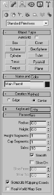
In the Command panel, activate the Create panel (as shown in Figure 2.11) by clicking on the Create tab (

With Standard Primitives selected in the Create panel's pull-down menu, as shown in Figure 2.11, click the Create Cylinder button. The Cylinder button will turn orange, and your cursor will turn from the default arrow to a cross.
Go to the Perspective view. On the Home Grid, click and drag the mouse in any direction to begin the radius of the cylinder. Drag the mouse until it makes a circle, as shown in Figure 2.12, and release the mouse button.
You'll notice that as you move the mouse up or down, Max will pull the circle into a cylinder. Settle on a height for the cylinder and right-click to create the cylinder (Figure 2.12). Don't worry about the size of the tube; we will modify it in the following steps to turn this cylinder into the top hanging bar for the mobile. Any size cylinder is fine for right now.
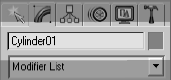
With the cylinder still selected in the Perspective panel, click the Modify tab (

You will rename the cylinder and size it to be a bar for the mobile. At the top of the panel, you'll notice a text box with Cylinder01 and a colored square next to it, as shown in Figure 2.13. The color swatch is the Object Color, and it helps you organize your elements in a scene. The color is easily changed by clicking on the swatch and simply choosing another color from the window that pops up (as shown in Figure 2.14). This color is not necessarily the color your object will render in the final output of your animation (for more on rendering in Max, see Chapter 11, "3ds Max Rendering"). However, we are not too interested in the color of the bar right now, so you can leave the cylinder the way it is, or you can change it if you desire.
You do need to change the name of the cylinder, however. Click in the text box and change it from Cylinder01 to Main Parent. This name signifies that the cylinder will be the top bar of the mobile and the top parent to the rest of the objects in the scene. For more on hierarchies, see the "Hierarchies" section earlier in this chapter.
You need to size the cylinder (Main Parent) to make it a bar. Under the Parameters heading in the Modify panel, you'll notice a handful of parameters for
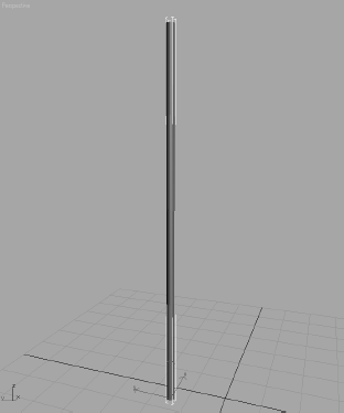
Main Parent, as shown in Figure 2.15. If you don't see anything there, make sure the cylinder is selected. The Modify panel will display the parameters for the selected object only. To adjust the parameters for the bar, you can type values directly into the appropriate boxes. You can also use the Up and Down arrows on the right either by clicking the arrows or by clicking and dragging up or down on the arrows. Change theradiusto 1, height to 100, and height segments to 1 (as shown in Figure 2.15). Your cylinder should look like a bar, as shown in Figure 2.16. For a quick explanation of the other cylinder parameters, see the note on the following page.


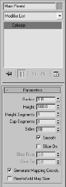
Every object in Max will have parameters that define it geometrically in the scene. The exact parameters that are available for editing depend on the object that is being edited. For this cylinder, for example, you've already seen what the Radius and Height parameters do. The Height Segments, Cap Segments, and Sides parameters determine how many polygons you will use to define the shape, and hence how smooth it appears. Because the bar will not bend, you do not need extra polygons along the length. Therefore, the Height Segment parameter was changed from the default of 5 to 1.
Positioning the Bar
Now you need to position the first bar, and then create copies for the other bars of the mobile, as shown in the following steps:
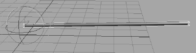
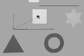
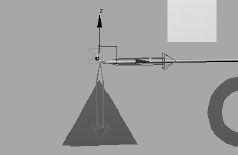
Click the Select and Rotate icon (

Clicking and dragging one of the axes will rotate the cylinder in that axis. For this step, click on the Y-axis rotate handle, which is the green circle, and drag the mouse to rotate the cylinder to the right of the screen as shown in Figure 2.17. The green Y-axis handle will turn yellow when you select it. (A gizmo's active axis handle is yellow.)
The bar needs to be rotated a perfect 90 degrees, and that is usually difficult to do by hand using the gizmo. Look at the bottom left of the Max UI, and you will see the orientation of the bar in three text boxes called the Transform Type-In boxes. You can enter a value of 90 in the Y-axis Transform Type-In box to set the bar to exactly 90 degrees, as shown in Figure 2.18.
Copying the Bar
In the next set of steps, you will copy the bar to make the other bars. Because the bar is already the size and orientation we need, it'll be much faster to copy three more bars and place them. Copying objects in Max is actually quite easy if you follow these steps:
Click the Select and Move Tool icon (

Note
You can also access the Move/Rotate/Scale and Select tools easily by right-clicking on the intended object to transform and picking the tool from the Quad menu that appears.
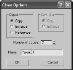
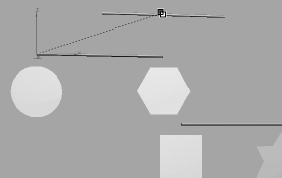
With the bar selected, hold down the Shift key and move the bar down in the Z-axis. A second copy of the bar will form: Move it down in the Z-axis with your cursor. As soon as you release the mouse button, the Clone Options window will ask you what kind of copy you want to make (Figure 2.19). We will cover the different types of copies and what they mean in Chapter 4, "Modeling in 3ds Max: Part I."
In the Clone Options window (Figure 2.19), keep the Copy button checked, enter 3 for the number of copies, and change the Name to Parent01. Click OK. Max will create three copies for you and position them as far down in the Z-axis as you moved the original clone while you had the Shift key pressed.
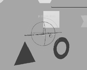
Use the Move tool to position the lower bars as shown in Figure 2.20; just don't move the bars off the Z-axis by moving any of them in the Y-axis. (We will keep all the bars in the Z-axis for simplicity's sake. After all, this is your first Max animation; there will be plenty of time for confusion later.)
Try to position the bars so that the second bar's center lines up with the left end of the top bar. The third bar's center should be lined up with the top bar's right end. The fourth bar can line up with the top bar. Each level of the bars should be about five units down in the Z-axis from the last bar. Now you're ready to make the hanging objects.
Creating the Mobile's Objects
What kind of mobile has only four sticks hanging on a string? You'll have to make some objects to hang from the ends of the bars. These objects will be simple shapes you can create with the following steps:
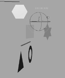
Activate the Front viewport by right-clicking inside it (by right clicking, you will not affect any of your selections and still be able to activate the viewport). Maximize that viewport with the Maximize Viewport Toggle icon (

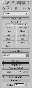
In the Command panel, click the Create tab and then click the Shapes button (

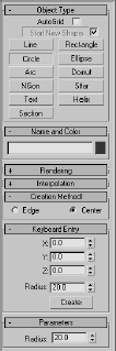
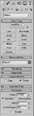
Let's start with a circle. Click the Circle button. Your cursor will turn to a cross as it did when you created the cylinder. This time, expand the Keyboard Entry rollout. Enter a value of 20 for the Radius under the Keyboard Entry rollout in the Create panel, as you can see in Figure 2.22. Click the Create button. A circle with radius 20 should appear at the origin. This is a way to make objects with precise dimensions, as opposed to clicking and dragging as you did to create the cylinder.
Max has given the circle you created the name Circle01, which is fine, so there is no need to change its name. Use the Move tool to position it under the second bar, lining up its center with the left end of the second bar as shown in Figure 2.23. Splines, including the circle you just created, are not renderable shapes by default. This means they will not render when you output your scene unless you specify otherwise. The circle will be displayed as a wireframe, even when the viewport is in Smooth + Highlights mode (also called Shaded mode) when objects are shown as solid in the viewport. For more on display modes in viewports, see the following brief sidebar.

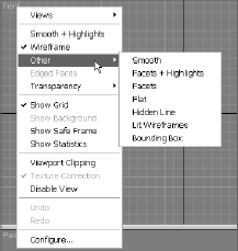
VIEWPORT MODES
In Smooth + Highlights mode, you see the objects in your scene as solid objects. This is the default mode for all the Max Perspective viewports, but not for the Modeling viewports such as the Front view. To switch from one view mode to another, right-click on the viewport name in the upper-left corner of the viewport. A menu will appear, as shown here. You can also use keyboard shortcuts to change from one viewport to the next.
You can select the view mode for that viewport by selecting it from the rightclick menu. Additional display modes are listed under Other on the menu.

Spline shapes, such as our lovely circle, are curves that need to be given a surface to be able to render as solid objects. To make the circle solid, you will extrude it by following these steps:
Select the
Circle01object (the circle) and click the Modify tab in the Command panel (
In the Circle01 name text box, click the Modifier List pull-down menu to access the many modifiers you can add to the circle (Figure 2.24). Under the Object-Space Modifiers heading, select Extrude.
In the box below the Modifier List menu, a new entry called Extrude should appear above the existing Circle entry for the selected Circle01 object. This box, called the Modifier Stack, is shown in Figure 2.25. The Modifier Stack displays all the modifiers that are contributing to the selected object, in this case the circle. The Circle modifier entry holds the original parameters of Circle01, while the new Extrude modifier entry holds the parameters for the extrusion you just applied to the circle. The circle now has a surface and is solid in the Perspective viewport (Figure 2.26).
Note
In 3ds Max 2008, a flat object may display with one black side, whereas previous versions of 3ds Max displayed flat objects properly. This is due to Backface Culling, which is a display optimization toggle that is now turned off by default in 3ds Max 2008. If you notice that one side of your flat object turns black, don't fret. Simply select the object and go to the Display tab of the Command panel (

In the Modifier Stack, click the Extrude entry to bring up its parameters. Play with the Amount parameter to give the circle extrusion some depth and make a cylinder.
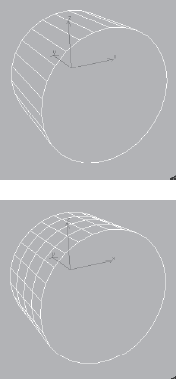
Let's go off topic just for a second to learn something a bit more general about Max. Go into Wireframe View mode in your Perspective window by right-clicking the Perspective viewport name in the upper-left corner and selecting Wireframe from the menu (you may also press F3). Make sure you right-click on the viewport name; right-clicking elsewhere in the viewport will bring up the Quad menu (which is explained in Chapter 3).
Now that you see the wireframe of the extruded circle, change the Segments of the Extrude modifier to see what happens. Figure 2.27 shows the extruded circle with Segments of 1 on the top, and Segments of 4 on the bottom. You'll see that now there are more geometry divisions (called subdivisions), which make the object smoother lengthwise. Because you don't need to bend this extruded cylinder, you do not need extra subdivisions along the length, so set the Segments back down to 1.
Back to the topic at hand, we need the circle to remain a flat disc, so set the Amount to 0.01 and keep the Segments at 1 as in the previous step.
Set the Perspective viewport back to Smooth + Highlights by right-clicking the viewport name, which is Perspective, and selecting Smooth + Highlights from the menu. You may also press F3 to toggle between the two display modes. You should now see a flat solid disc as shown in Figure 2.28.
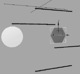
Create a hexagon for the second shape. Go back to the Front viewport. In the Command panel, click the NGon button as shown in Figure 2.29. In the Parameters heading, set the Sides to 6 for a hexagon. An NGon is a polygon with N number of sides. In this case, N is 6 to make a hexagon. In the Front viewport, click and drag to create the hexagon to a radius of about 20.
In the same way you created the disc using an Extrusion modifier on the circle, make a hexagon into a solid shape by adding an Extrusion modifier to it. Select the hexagon (named NGon01). In the Modifier panel, click the Modifier List menu and select Extrude (as shown in Figure 2.25). The NGon01 object will now have its own Extrude modifier in the Modifier Stack.
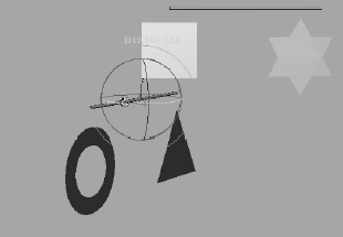
Use the Move tool (

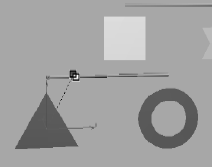
Create four more shapes and place them to line up under the ends of the remaining bars as shown in Figure 2.31. You will need to create and extrude the remaining four shapes all at about the same size (radius of 20). The following table shows you the remaining shapes and what Object Type button to use to create them and what their names will be in the scene. To avoid any confusion when we begin to set up the hierarchies for animation, keep the naming as shown here:


MOBILE OBJECT | CREATION TYPE | OBJECT NAME |
|---|---|---|
Square | Use the Create Rectangle button | Rectangle01 |
Star | Use the Create Star button | Star01 |
Triangle | Use the Create NGon button with three sides | Ngon02 |
Donut | Use the Create Donut button | Donut01 |
You should already have created these first two shapes:
MOBILE OBJECT | CREATION TYPE | OBJECT NAME |
|---|---|---|
Circle | Used the Create Circle button | Circle01 |
Hexagon | Used the Create NGon button with six sides | NGon01 |
Note
If you click and drag to create a shape in the Perspective viewport and nothing happens, you will need to switch to one of the Orthographic views. In this Mobile example, make sure to create all the shapes in the Front viewport for simplicity's sake.
There you have it—a completed mobile model ready to set up and animate. The next sections of the chapter will take you through setting these objects up for animation in hierarchies so that when one bar rotates, its shapes and any bars beneath it also rotate with it. Go put your feet up and watch something dumb on TV for a little while; you've earned a break. It's actually important to take a break at this point, and make sure what you've gone through makes some sense. Feel free to go back and redo the exercise in part or in whole. In the next section, we will tackle hierarchies and setting up the mobile objects to animate properly.
Before we continue with the next step in the Mobile exercise, let's take a look at hierarchies in action. Here is a quick introduction to how hierarchies work.
Parent and Child Objects
In the following steps, we will create a hierarchy of a few boxes to see how the relationship works when parents move, taking their children with them, and how children can move independently under their parents.
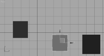
In a new scene, in the Create panel, click Box to create a new box. Click and drag in the Front viewport and draw out a box. Notice that when you drag the first time, a flat box is created. When you are happy with the size of the rectangle, click once and drag to "pull out" the third dimension of the box to give it depth. Click again when you are happy with the 3D box and Max will create it. Your cursor will still be active in the Create Box tool. Click and drag to create two more boxes of approximately the same size to the right of the first box, as shown in Figure 2.32.
You need to set up a hierarchy so that the box on the right is a child of the box in the middle, which in turn is a child of the box on the left, like a row of ducks. In the main toolbar across the top of the UI, click the Select and Link tool (

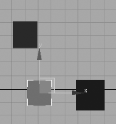
In either the Front or Perspective viewports, click the box on the right and then drag the mouse over to the box in the middle. A dashed line and a cursor will change while you do this, as shown in Figure 2.33. When you release the mouse button, the two boxes will flash a white outline. This indicates that the link worked. The box on the right is now a child of the box in the middle.
Click the Move tool (

Click the Select and Link tool (

Now let's set a few keyframes on these boxes to get our juices flowing.

Setting Keyframes
The Time slider is at the bottom of the screen, as shown in Figure 2.35. The Time slider is used to change your position in time, counted in frames. As you read in the previous chapter, frames are the common increment for denoting time in an animation. You'll read more about the Time slider in the next chapter.
Now scrub the timeline between 0 and 20, and you will see your animation. Even though you did not set any keyframes on the box to the right, it will follow along with both the left box and the middle box, doing a combination of their moves. The middle box goes with its parent, the left box, and its own animation, sliding down the viewport in the Y-axis. This is a simple hierarchy showing you how the relationships between objects build animation. You will use the same theory to build the animation for the Mobile exercise.
Before you continue on to the next exercise, make sure to turn off AutoKey.
Hierarchies for the Mobile
You will create the hierarchies for animation of the mobile using the following steps:
Remember, the Select and Link tool works from the children up the hierarchy to the top parent. You will link the shapes to their respective bars up the mobile. Click the Select and Link tool (

With the Select and Link tool still active, click and drag from the donut shape to the bar above it, as shown in Figure 2.37.
With the Select and Link tool, click and drag from the bottom bar that holds the triangle and donut to the square shape above it, as shown in Figure 2.38. The bar is hanging from that square as if this were a real mobile, so you would link it as such. If you want to check your work, select and move the square and the bar. The shapes beneath it will move with the square. Just make sure to press Ctrl+Z to undo any moves you made to check the linking.
Now you just need to use the same steps to link the rest of the mobile:
Click and drag with the Select and Link tool from the square to the bar above it.
Link from the star to its bar.
Link from the bar above the star and square to the top bar, as shown in Figure 2.39.
Link from the hexagon to its bar.
Link from the circle to its bar.
Link from the bar above the circle and hexagon to the top bar, as shown in Figure 2.40.


You can refer to Figure 2.41 for a diagram of the linking order. It doesn't matter in what order you link the pieces, as long as you link from the bottom pieces up the chain.

Pivot Points
Now you've linked all the pieces of the mobile and created your first animation hierarchy. It's time to rotate parts of the mobile and test your handy work. This will be the last step before you animate the mobile. To test the mobile, select the bottom bar and rotate it on the Z-axis in either direction. Figure 2.42 shows the rotation of the bottom bar. Notice that the Rotate gizmo is at one end of the bar and not in the middle. You should also notice that the bar (along with the triangle and donut) is rotating around the end of the bar, although it should rotate in the middle, where the string would be hanging it from the square right above it.
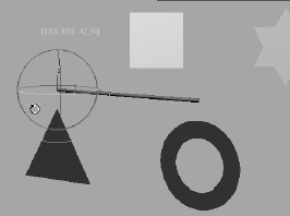
Your results might be slightly different from what is shown here. Your bar might not rotate around the same end or it might rotate somewhere else along the cylinder. This is perfectly normal. The important thing is where the pivot point of the object is—and that pivot should be in the middle of the bar.
Simply put, the pivot point of an object in Max is the point about which it rotates. It is also the point on the object that defines the point in coordinate space where the object resides. So a coordinate of (2,6,0) for the position of a cube, for example, technically describes the pivot point of that cube to be at the location (2,6,0).
Because the pivot of the bottom bar is not in the middle of the bar, you will have to move the pivot to the middle. To do so, follow these steps:
Use Ctrl+Z to undo any rotations you have already put on the bottom bar. Click the Move tool (

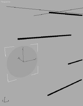
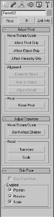
At the top of the Hierarchy panel, make sure the Pivot button is active and then click the Affect Pivot Only button to activate it (the button will change color). This will tell Max to move only the pivot point of the currently selected object and not to move the entire object. Your gizmo icon will change, as shown in Figure 2.44.
Click the X-axis Move handle (the small red arrow inside the larger outline of an arrow) and move the pivot along the length of the bar to the middle of the bar, as shown in Figure 2.45.
In the Hierarchy panel, click the Affect Pivot Only button again to turn it off. Your cursor will return to the normal Move Tool gizmo. Select the Rotate tool from the main toolbar (

To make sure the pivot points are all in the middle of the respective bars, check the other bars in the mobile. If not, use the previous steps to relocate the pivots to their proper places.

In this animation, we will rotate only the bars of the mobile. Don't worry about rotating or animating the shapes for now. We will revisit this exercise in Chapter 8, "Introduction to Animation."
Scrub the Time slider to 0. If it is not already on, turn on the Auto Keyframe feature by clicking the Auto Key button (

Move the Time slider to frame 50. Click the Rotate tool (or press the hot key E for the Rotate tool), and select and rotate the bottom bar (which will also rotate the triangle and donut shapes beneath it). You can rotate the bar in either direction on the Z-axis, as shown in Figure 2.47. Give it a few full rotations all the way around. Don't be shy.
You can scrub the animation to check it out. The bottom bar and its shapes should be spinning. Make sure you go back to frame 50 in the Time slider. With the Rotate tool still active, select the second bar from the bottom (the bar with the square and the star shapes), and rotate it in either direction in the Z-axis. Figure 2.48 shows how the bottom bar follows along.
While still at frame 50, select the third bar from the bottom (the bar with the circle and the hexagon) and rotate it in either direction on the Z-axis. The circle and hexagon rotate with the bar, as shown in Figure 2.49.
With the Rotate tool, select the top bar and rotate it in either direction on the Z-axis. The entire mobile will rotate along with it, because the top bar is the top parent of this hierarchy (Figure 2.50).

Note
You may have noticed that this exercise asked you not to animate the rotation of the shapes linked under the bars. This was to avoid overloading you with information. If you animate the shapes under the bars to rotate, you will probably get some strange results when you play back the animation. The shapes and some of the bars linked below the animated shapes will not rotate properly. We will revisit this exercise to learn how to properly animate the shapes and the bars in Chapter 8.
Understanding the underlying technique used here is important, so doing the exercise more than once is not a bad idea. These things can be frustrating, so take it easy and when you get confused or stuck, back up and try again.
In this chapter, you learned how project management and file workflow help you keep things organized. You learned how to navigate the User Interface to create and manipulate objects in the viewports. You learned about hierarchies and how to link objects together to create a hierarchy useful for our mobile animation. Finally, you learned how pivot points are used, and you also learned how to create animation using the Auto Key function.