
Modeling in 3D programs is akin to sculpting or carpentry; you essentially create objects out of shapes and forms. No matter how you look at it, even a complex model is just an amalgam of simpler parts. The successful modeler can dissect a form down to its components and translate them into surfaces and meshes.
3ds Max's modeling tools are incredibly strong for polygonal modeling. The focus of this book will be on polygonal modeling because the majority of 3ds Max models are created with polygons. In addition to mechanical models, in this book you will model an organic model—an alien creature—and use that model to animate a character using SubDivision surfaces.
In this chapter, you will learn modeling concepts and how to use 3ds Max modeling toolsets. You will also tackle two different models to get a sense of a workflow using 3ds Max.
Topics in this chapter include:
Planning Your Model
Modeling Concepts
Modifiers and the Modifier Stack
Look at the Mesh You Got Us Into!
Editable Poly Tools
Modeling a Chest of Drawers
Modeling a Hand
The most important thing to know before you begin to model is exactly what you are going to model. That sounds obvious, but it's true. You need to think about your model and gather as many references as you can. The best training you can hope to gain is simply by observing the core elements and forms that make up objects in everyday life. Learn how to dissect things around you into component shapes that you can picture in a 3D window. When you look at a barbell, for example, you should see several cylinders connected to each other. When you see an office chair, you should see a few boxes and cylinders arranged and rounded at the edges. When you begin to see objects in this manner, the idea of modeling them may not seem quite as daunting.
"Yeah, but all my friends can sit down and model anything they want." Be that as it may, if you are a novice to 3D, surround yourself with references. Even if you are not new to 3D or to modeling, you should surround yourself with as many references as you can. Not having a clear picture in your head of where you need to go for your model will just aggravate the process and give you a slack result.
Take pictures all around the proposed object. Get the dimensions, sizes, angles, and slopes of the surfaces of your subject. You could even try to re-create the object in a different medium. Try sketching the subject, or grab some children's Play-Doh or a plate of mashed potatoes and make a rough sculpture. It may seem like a lot of effort to build something trivial, but it will pay off in the long run.
But enough of that old lecture.
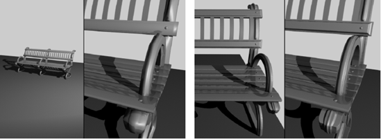
Your first question should be, "How detailed should I make the model?" As you may have read in the first chapter, it's always a good idea to match the level of detail for a model to what is needed in the shot. If you are featuring the object up close and personal, then you should take care to build it with extra detail, adding as many polygons as it takes to make it look good and still render. If, however, the object is far away and half obscured, detailing the heck out of it would be a waste of time. In Figure 4.1 on the left, you can see a park bench in a far shot compared to a view of the bench up close on the right. It would be a waste of effort and time to detail the bench to exacting levels when the bench will be seen only in a far shot.
You should ask yourself what the model will be used for when you are deciding how best to detail it. If you are not sure how the model will be used in the end, it's generally best to create as much detail as you think necessary. You can always prune down the details later if, for example, your scene ends up very large and will not render.
Here's another thing to confuse you: You can always add detail to a model with texturing. Textures, when applied well, can really turn an otherwise ho-hum model into a spectacular object when rendered. You can easily add details such as grooves, dents, and engravings with special texture maps called bump maps or displacement maps. You will learn about these maps in Chapter 7, "Materials and Mapping." Don't worry about these things yet, though. Most people begin by putting all the details they can into their model, and as they gain more experience, they start to realize that some of the modeling work can be deferred until the texturing phase.
To get a foothold in modeling, you will need to understand a number of things. If you are not new to CG or are desperate to get started, feel free to skip ahead and start modeling. However, you still might want to peruse this section for some concepts and terms that may make things easier for you in the coming exercises.
Polygons
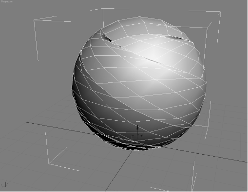
A polygon is a surface created by connecting three or more points in 3D space. This flat surface connects to other polygons to form more intricate surfaces. In Figure 4.2, you see a sphere. The facets of the sphere are polygons, all connected at common edges at the correct angles and in the proper arrangement to make a sphere.
The points that generate a polygon are called vertices. The lines that connect the points are called edges. If the polygon has three vertices, its surface is called a face. Polygons are made up of triangular faces by design. In the example of the sphere in Figure 4.2, the polygon's facets all have four vertices

The graphic shows the same sphere with one face selected. See how the face is half of the polygon, using three of its vertices.

The more polygons you have in a model, the more detailed it becomes. However, greater numbers of polygons tax your system and take longer to render. This is where the term low-poly modeling originates. In computer or console games, the machine renders the scene on the fly, so its computation requirements are strict. The fewer the polygons in the scene, the faster the game can play back. Games frequently use low-poly models to maximize the effect in their game without sacrificing precious computational cycles.
Higher-resolution models are typically used in television and film, because the scenes are all rendered beforehand and then laid off to video tape or output to film. A computational ceiling is still dictated by the machines that are used in creating the TV or film animations, however, so it is always a good idea to be smart when creating models.
Primitives
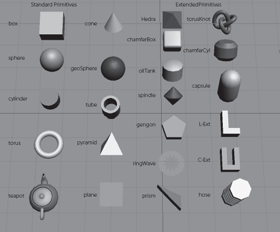
Primitives are the basic 3D geometric shapes that are automatically generated by 3D modeling applications. As such, they do not need to be constructed from scratch. A considerable amount of modeling (perhaps most) begins with primitives, which are then edited and used with other primitives to create more complex objects. Use primitives as the core of your object. For example, to sculpt an apple, you might start out with a sphere primitive.
As you can see in Figure 4.3, 3ds Max affords you plenty of primitives to choose from for your original form. All of these primitives have their own parameters for customizing the form to your liking. You have already seen how to create some of these objects in the Mobile exercise in Chapter 2, "Your First Max Animation."
Objects such as the primitives would be useless in 3ds Max if you could not edit them to suit your needs. For example, you could sculpt a sphere into the shape of an apple. To sculpt a surface, you will need to convert your object (such as the sphere for the apple) into an editable object, frequently called a mesh, to get to the object's component level where you can move points and reshape faces that make up the object or primitive. We will look at that in the next section.
Meshes and Sub-Objects
Once you have chosen a primitive that will best work for your intended model, you begin the modeling process by changing the primitive into a mesh object to access the components of the object with which you will edit the model (such as vertices, faces, etc.).
In 3ds Max, mesh objects are defined by smaller component pieces that form the object as a whole. The smaller components (called sub-objects) can be manipulated to adjust the shape of the object or to form more complex models. Once you convert your object in 3ds Max to an editable object such as a mesh, you can edit using the sub-objects available for that object.
For instance, mesh models break down your object into a number of individual flat surfaces—polygons and faces. With meshes, you can select any of the sub-objects at different component levels such as the polygons, vertices, or faces of the mesh to make adjustments while sculpting your model.
In 3ds Max, there are two ways to create a mesh object: by applying a modifier to the base object or primitive or by converting the primitive to a mesh. Both methods give you access to the sub-object level for editing. The one big difference, however, can be critical if you need to edit the base object—for example, if you want to change the radius of a primitive sphere after you start editing it as a mesh. Instead of converting, you are better off using the modifier method because it preserves the original primitive object intact and allows you to modify the object's original parameters (such as radius for a sphere) even after you begin to edit the mesh.
In this exercise, you will create an object and turn it into a mesh. Follow these steps:
Create a sphere in a new scene using the Create panel. You will turn this object into a mesh to check out the sub-objects at your disposal.
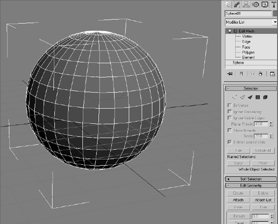
With the sphere selected, switch to the Modify panel. Figure 4.4 shows the newly created sphere. Notice the Sphere heading in the Modifier List on the right.
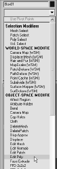
With the sphere selected, choose Modifiers → Mesh Editing → Edit Mesh. This will apply an Edit Mesh modifier to the sphere, giving you access to the sub-objects that a mesh affords you.
The Modifier Stack will display a heading called Edit Mesh. Highlight Edit Mesh in the Modifier Stack. You should see something like what is shown in Figure 4.5.
Under the Selection heading in the Modify panel, select the type of sub-object you would like to begin editing. Choose the first icon (

As you can see in Figure 4.6, small dots appear on the sphere. They are the vertices you can now select. Choose the Move tool and select one of the vertices on the sphere. Click and drag to move the vertex anywhere to sculpt the surface of the sphere, as shown in Figure 4.6.
Change your sub-object selection to polygons by choosing the Polygon icon (

Click on a polygon to select it. Notice that the polygon turns red in the viewport. Move the selected polygon around to see how the surface of the sphere mesh changes (Figure 4.7).
Try selecting the other sub-object types and changing the shape of the sphere.
In the Modifier Stack, click on the original sphere entry. You will still have access to changing the radius and other parameters of the original primitive. Changing any of these parameters does not negate the Edit Mesh modifier.


As you can see, you have greater control over the shape of your model once you access the sub-object levels of an Edit mesh. You'll see quite a bit of mesh editing in the exercises throughout this book. One exercise you can do now quickly is to try to sculpt a simple cartoon head using nothing but sub-object manipulation on a base sphere.
In some 3D packages, you have inherent access to a model's components (such as a vertex or face). However, with 3ds Max you will need to either convert created objects into meshes or add the appropriate modifier to create a mesh, as you did in the previous exercise, to manipulate the sub-objects. You will be modeling with meshes later in this chapter, and you will learn other ways to access sub-objects on a model.
Modifiers, as you have already seen, are a way to edit your objects in 3ds Max. In almost all cases, you can apply several modifiers to an object to get the desired result. In the Modify panel's Modifier Stack, you can access any of those modifiers to change any of its parameters at any time in your modeling. This is perhaps one of the best aspects of modeling in 3ds Max.
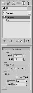
Figure 4.8. The Twist modifier is now applied to the box. You can still access the original parameters of the box.
3ds Max has tons of modifiers that accomplish any number of tasks. These tasks need not be limited to editing models, though; many modifiers work well in animation and dynamics chores as well. In this section, we will cover a few modeling-specific modifiers and more importantly, we will see how the Modifier Stack operates.
Applying Modifiers
Let's take a quick look at how modifiers work on editing objects. In the following steps, you will apply a few modifiers to an object.
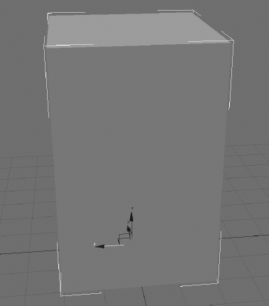
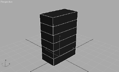
In a new scene, create a tall box in the Perspective viewport, as shown here. The box should have a height of at least 45, with a width and length of about 20
With the box selected, choose Modifiers → Parametric Deformers → Twist. The box should now have an orange outline, and Twist should appear in the Modifier Stack. Go to the Modify panel to see the Modifier Stack, as shown in Figure 4.8. Click Twist in the Modifier Stack to access its parameters.
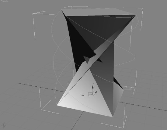
Click the Angle spinner and drag the mouse to increase the angle to 240 or so. As you can see in Figure 4.9, the box gets completely strange. You can see the box twist pretty nicely at first, but the higher the Angle on the Twist, the more shearing the box will undergo, to the point where it no longer resembles what a twisted box should look like.
The box is suffering from a case of low definition, meaning the box does not have enough segments to handle the twist deformation without turning inside out. You will need to add more segments to the box for a smoother twist effect. In the Modifier Stack, click Box to access the parameters for the box, before the Twist modifier.
To better see the effect of adding more segments to the box, enable Edged Faces in the viewport (right-click Perspective, which is the viewport name) and select Edged Faces from the menu.
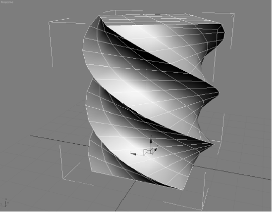
Click the Length Segs parameter spinner and increase the value to 4. Increase the Width Segs to 4 and the Height Segs to 16. As you increase the segments in the original box, the Twist Modifier takes on a much nicer shape. Figure 4.10 shows the box with more segments.
You can increase the segments as much you prefer; however, it's best to use the fewest number of segments that will give you the desired result. Increasing the number of segments essentially increases the polygons in the surface.
Now add another modifier to the box. Select the box and highlight the box entry in the Modifier Stack. Choose Modifier → Parametric Deformers → Spherify. Your box should look like a ball (Figure 4.11). Neat!
Play with the Spherify modifier's only parameter (Percentage) to see how the twisted box can turn into a sphere. Although this is kind of a neat trick, you don't really need this modifier, so go ahead and remove it from the stack. In the Modifier Stack, click the Spherify entry and click the Trash Can icon (

Modifiers are powerful editing and animation tools. Take some time to play around in a scene such as the one from the previous exercise. Apply different deformers to objects and see what they do. It's really best to learn by experience sometimes. The Parametric Deformer modifiers are especially fun to play with, as you can see.
You have not seen the last of modifiers in this book; they are an integral part of the 3ds Max workflow, and we will use them throughout this book. We will take another look at the Modifier Stack in the next section.
Modifier Stack with a Side of Maple Syrup
The Modifier Stack displays the modifiers added to any objects. It gives you access to any of the parameters for the modifiers applied to the object, as well as the original parameters of the object itself. When working with the Modifier Stack, you can access several options through the icons below the stack itself, as shown in Figure 4.12.
Pin Stack If you want to freeze the display on the Modify panel controls on the currently selected object, click this icon. Pin Stack locks the stack and all the controls in the panel so that you can see that object's stack even while you have other objects selected in the scene.
Show End Result When on, it shows the effect of the entire stack on the selected object. When off, it shows the effect of the stack only up to the currently highlighted modifier.
Make Unique With a certain type of object duplication (instancing), making any adjustments to the instanced copy also reflects in the original object. Make Unique separates the objects and disallows a shared adjustment, so if you apply a modifier to an instanced copy, it will not reflect in the original object when Make Unique is applied.
Remove Modifier This deletes the current modifier from the stack, eliminating all changes caused by that modifier.
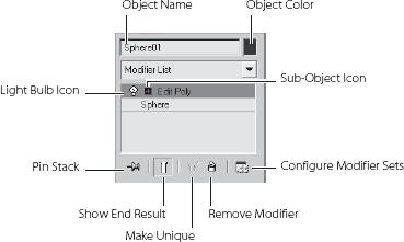
Configure Modifier Sets This displays a menu that allows you to configure the display of the Modify panel and choose which modifiers will be available to you directly from the Modify panel, without having to access the drop-down list.
Sub-Object Icon The plus or minus icon to the right of the Modifier name signifies that you have access to the sub-object (or sub-modifier) levels.
Light Bulb Icon This turns the effect of the modifier on and off. This is very useful for troubleshooting and verifying the effect of a particular modifier in a stack.
Order in the Stack
Unless changed, the Modifier Stack contains a history of an object's modifiers in the order they were applied. The Stack is read and applied to the object from the bottom going up, with the original object's entry at the very bottom. As you can imagine, the order in which you stack your modifiers is very important. You can get very different results from the same objects with the same modifiers in a different order.
Fortunately, changing the order of modifiers in the stack is very easy. In the Modifier Stack, click the modifier you want to move and drag it to its new position in the stack. Once you release the mouse button, a blue line will demarcate where in the stack the modifier will be placed.
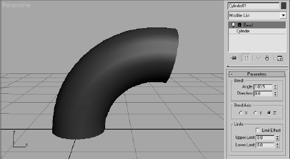
For example, you can start with a cylinder and apply the Bend modifier (Modifiers → Parametric Deformers → Bend) to the cylinder first, as shown in Figure 4.13.
Now if you want to pinch in or taper the bent side of the cylinder, you can add a Taper modifier (Modifiers → Parametric Deformers → Taper) to the stack. The results won't look the way you would expect, as you can see in Figure 4.14.
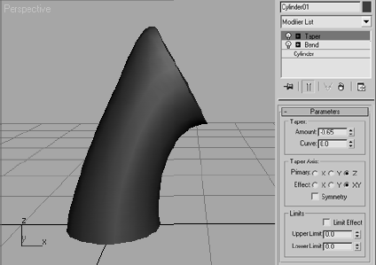
Figure 4.14. Trying to taper the bent side of the cylinder does not work with the Taper modifier—yet.
Now go to the Modifier Stack, click and drag the Taper modifier, and move it below the Bend modifier (Figure 4.15). These are the results you want to see. You want to bend the Taper, not taper the Bend. Using this principle will help you figure out how to order the modifiers in the stack.

As you saw earlier in this chapter, to access the sub-object level of objects, you will need to turn them into a mesh. You've seen how you can add an Edit Mesh modifier to an object so you can begin to sculpt the surface using vertices and faces. There are tons of editing tools inherent in meshes.
When you create a mesh from an object, you not only have access to the sub-objects of that object, but you also have access to a host of tools to allow you to edit the surface. How do you get into a mesh? There are at least four different ways.
Converting versus Adding a Modifier
You can add the Edit Mesh or Edit Poly modifiers to an object, or you can convert to an editable mesh or editable poly. Converting to an editable mesh or adding an Edit Mesh modifier is roughly the same; they both host the same toolset and allow you the same subobject levels for the mesh. However, adding a modifier allows you to edit the parametersof the original object, as you may have seen earlier in the chapter.
To experiment with the modifiers, try this exercise:
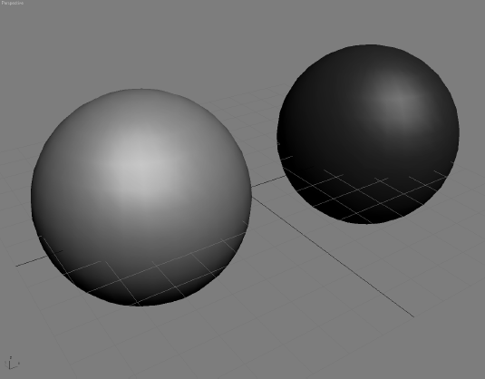
Create two spheres in a new scene, and place them side by side, as shown in Figure 4.16.
Select the sphere on the left and apply an Edit Mesh modifier to it (choose Modifiers → Mesh Editing → Edit Mesh).
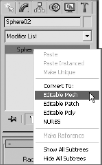
Select the sphere on the right and convert it to an editable mesh by right-clicking on the sphere's entry in the Modifier Stack. From the right-click menu, choose Editable Mesh under the Convert To: heading, as shown here.
Notice that the Editable Mesh sphere no longer has the same Modifier Stack entries. This sphere now displays as Editable Mesh in the Modifier Stack. You should also note that the Editable Mesh sphere also has a rollout at the bottom of the Modifier panel called Surface Properties. Aside from those two issues, the modifier and the conversion are exactly the same.
The Convert method has its own advantages, however. Converting to an editable mesh, as opposed to applying the Edit Mesh modifier, saves memory and is more efficient because 3ds Max doesn't have to save the base object's parameter information. However, using the modifier gives you a little bit of comfort if you have commitment issues because you can always go back to the original object and remove the Edit Mesh modifier at any time. You cannot reconvert an editable mesh back to its original object.
Mesh versus Poly
How do you decide whether to use Edit Mesh or Edit Poly modifier, or editable mesh instead of editable poly? Which is better to use? Well, so far you have seen the Edit Mesh modifier and the Editable Mesh one. A more up-to-date toolset for sub-object tools is obtained through the Edit Poly modifier or Editable Poly, and it is the preferred way to go for many 3ds Max artists.
Note
Why show the Edit Mesh modifier and Editable Mesh? They are both good to know, and you should understand the similarities and differences in how they function. Having said that, we'll concentrate on the Edit Poly modifier and Editable Poly for this chapter's exercises.
Edit Poly Modifier/Editable Poly
The Edit Poly modifier gives you plenty of controls to edit an object, just as the Edit Mesh modifier does. Figure 4.19 shows the Modify panel entries for the Edit Poly modifier on a sphere.

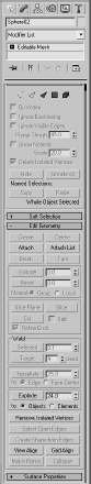
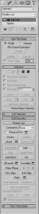
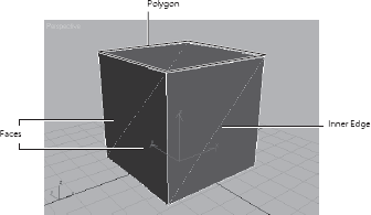
Figure 4.20. Polygon faces on this box have three edges or sides, making them triangular. A polygon on this box has four edges, or sides, making it a square.
The differences between mesh and poly are few. Editable mesh gives you a sub-object level called faces that are polygons with just three edges (they have three vertices). Figure 4.20 shows you faces on a box object.
When modeling with an editable mesh (or through the Edit Mesh modifier), having faces gives you an inner edge where the faces meet along the center of the polygon. The inner edge can cause all kinds of problems even when you are working in Poly mode. An editable poly is similar to an editable mesh, but it gives you access to four-sided polygons instead of faces. It also hosts a slew of other, more refined tools and selection options.
In addition, the toolsets found in the Edit Poly/Editable Poly are more fleshed out than Edit Mesh/Editable Mesh and have been updated more, so they will give you slightly more options. The major difference between the toolsets in the Editable Poly and Edit Poly modifiers is that you have inherent access to SubDivision modeling on the editable poly.
In the next section, you will learn about the Edit Poly modifier and the editable poly.
Edit Poly/Editable Poly Tools
In this section, you will explore the actual toolsets in the Edit Poly/Editable Poly world. Most of these toolsets will also apply to the toolsets you will find in the Edit Mesh/Editable Mesh world as well, although some may be used slightly differently. In either case, using an Edit Poly modifier or an editable poly is preferred.
Similarly, the toolset in an editable poly is very similar to those found with the Edit Poly modifier; so here is a rundown on the rollouts and toolsets you will find for the editable poly. (Many cross over for the edit poly as well).
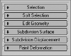
When you convert a primitive to an editable poly, you can see the controls for manipulating an object at sub-object levels in the Modify panel interface. They are very similar to the sub-objects you learned about earlier in the book with the Edit Mesh modifier. In all, there are six rollouts (as shown here). The main ones are Selection, Edit Geometry, and Subdivision Surface
Selection Rollout
The Selection rollout contains tools used to access different levels of the object's sub-objects and their display in the viewport. You can also find information about the selected components in this rollout, as shown in Figure 4.21.
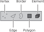
When you first create an editable poly and access the Modifier panel, you are in the Object level, meaning you will select the object. By clicking the different sub-object–level icons at the top of this rollout (see Figure 4.22), you can access the different selection levels as well as their relevant tools. Deselecting the icon will return you to the Object selection level.
You can also select the desired sub-object level by clicking the plus sign (+) next to the Editable Poly entry in the Modifier Stack and selecting one of the entries, as shown here.
Here are the different sub-object levels for an editable poly:
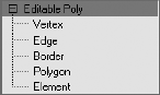
Vertex Vertices define the structure of other sub-objects that make up the poly. They are simply points in space. However, when a vertex is moved, the geometry that they form is changed accordingly. While your editable poly is selected, you can press 1 on the keyboard to select the Vertex level.
Edge The line connecting two vertices together is an edge and, therefore, creates the side of a polygon. Edges can be shared by only two polygons. Press 2 to enter Edge level selection.

Border A border is the edge of a hole. A surface's edge contains polygons that are not flanked by other polygons; in essence, they are on the edge of the surface. The row of edges on the perimeter of that surface is the border. You may invoke Border-level selection by pressing 3.
Polygon A polygon is a flat shape created by connecting three or more vertices, forming a closed shape. Polygons are what actually render when you output your scene in rendering. Press 4 to enter the Polygon level.
Element An element is one of two or more individual mesh objects (that is, groups of contiguous faces) grouped together into one larger object. For example, if you attach one box to another, you create one mesh object from the two boxes. Each box is now an element of the object. Any function you perform on that object affects all its elements. However, you can manipulate the elements independently at the Element sub-object level. When you attach two or more meshes together, for example, the object becomes a larger single object in 3ds Max. However, the original meshes attached to each other are still accessible as Elements of the larger grouped object. Press 5 to enter the Element level.
The Selection modifier has a few options that will help you quickly alter your selection to better suit your needs. The following covers a few of the important selection options:
By Vertex When you click the check box, you can select sub-objects by selecting the vertex they are near. This feature is grayed out when you are in Vertex mode.
Ignore Backfacing When you click the check box you can select only the sub-objects that are facing you. With the default, which is off, you can select any sub-object(s) whether they are facing you or even visible. Think of it like selecting a dot on an orange. With Ignore Backfacing turned on, you can select a dot only on the side of the orange you can see. With Ignore Backfacing off, you can select any dot—even if it is on the side of the orange that's away from you.
By Angle When you select a polygon with By Angle enabled, 3ds Max will also select the neighboring polygons based on the value given for the angle in the text box next to this check box. This value determines the maximum angle between neighboring polygons that may be selected.
Shrink When you have made a sub-object selection, but you feel the selection is too wide, use Shrink. Shrink will deselect the outermost sub-objects to shrink your selection.
Grow Conversely, you can make a small selection of sub-objects and use Grow to increase the selection area outward in all available directions.
Loop Once you select an edge, you can propagate that selection to all the edges continuously around the mesh object by clicking the Loop icon. In the image on the left, a single edge is selected. The entire loop of edges is selected in the image on the right.

Ring Similar to the Loop function, Ring propagates an edge selection to the ring of edges perpendicular to the edge selected. In the following image on the left, there is a single edge selection. In the image on the right, the edges are selected with the Ring function.

Soft Selection Rollout
As you already know, a regular selection selects only what you pick in the viewport for editing. You can, however, create a soft selection (shown in Figure 4.23), where a falloff effect emanates from your selection area toward the unselected sub-objects. In this case, the unselected sub-objects gain a partial selection value that is displayed in the viewports as a color gradient on the vertices or faces. When you apply a transformation—for example, if you move the soft selection—the actual selection will transform at a 1:1 ratio, while the falloff area of the soft selection will react at a lesser ratio according to the gradient falloff. This is similar to picking up a tablecloth with two fingers. The cloth between the two fingers is the full selection, while the cloth around the fingers falls off and does not lift up off the table as high as your fingers.
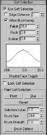
You can adjust the amount of falloff using the Falloff, Pinch, and Bubble parameters. In Figure 4.24, a sphere's vertices are being pulled outward with a soft selection. The area in the falloff, as you can see, is smoothly holding back as the main selection vertices are pulling out. The sphere in the back of the viewport in Figure 4.24 has a vertex pulled out without the benefit of a soft selection.

Figure 4.24. Front sphere with Soft Selection enabled and back sphere without Soft Selection enabled
Edit (Sub-Object) Rollout
These rollouts provide specific tools for editing the sub-object of your poly object. There are tools that are specific to the sub-object and ones that are the same for all sub-objects. The rollout heading name changes to reflect the sub-object level you are currently in and shows you the tools available for just that sub-object.
Try this exercise:
In a new scene, create a sphere. Convert the sphere to an editable poly.
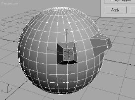
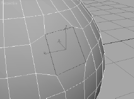
Select the Poly sub-object level and select a single poly on the sphere, as shown here. Make sure Soft Selection is not enabled.

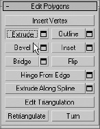
In the Edit Polygons rollout, choose Extrude, as shown here
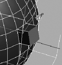
The appearance of your mouse pointer in the viewport will change. Click on the polygon you already have selected, and drag the mouse up to extrude the polygon out from the sphere. If you drag the mouse down, the polygon will extrude into the sphere, creating a square tunnel. Pull the polygon out as shown and release the mouse button
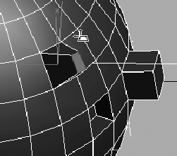
Select another polygon and extrude the face inward by dragging down on the cursor, as shown here.

Select a third polygon on the sphere, and this time select the Bevel tool in the Modifier panel. Similar to an Extrude, Bevel allows you to taper the extruded polygon. Click the polygon, and drag the mouse to pull the polygon out. When you release the mouse button, 3ds Max allows you to select the taper amount by moving the mouse up or down. When you have the desired taper, as shown here, click once to exit the tool and set the bevel as you see it here.
This rollout (Figure 4.25) is the same for all the sub-objects. These tools allow you to edit your object. You will be using many of these tools in the upcoming Chest of Drawers and Hand exercises in this chapter.
Subdivision Surface Rollout
You have probably heard of subdivision (SubD) surfaces and SubD modeling. A SubD surface is a surface that has been divided to have more faces. However, the SubD surface retains the original object's general shape, which is sometimes called a cage. You subdivide to add more detail to a model, but you can still edit the original cage of the model to alter its overall shape and form.
The Subdivision Surface rollout lets you access tools specific to modeling with a subdivision surface, as shown in Figure 4.26.

You will be modeling with subdivision surfaces a little bit later in the Hand exercise in this chapter and then again in Chapter 6, "Character Poly Modeling."
The Edit rollout tools give you access to functions such as Extrude and Bevel to help you shape your model. The next section, "Editable Poly Tools," will give you some more experience with these toolsets. You will also use many of these tools in the Chest of Drawers exercise in this chapter.
Let's experiment with some of the other Editable Poly tools. Dive right into the following exercises.
Extrude
When you extrude a vertex, 3ds Max moves it along a normal—that is, a line that is perpendicular to the surface in most cases. The extrusion creates new polygons that form the sides of the extrusion that also connect the vertex to the object.
We will start by extruding a vertex on a sphere:
Create a sphere by going to the Create panel and selecting Sphere. Create the sphere with about 20 units radius. Convert the sphere to an editable poly by right-clicking the sphere and choosing Editable Poly under the Convert To heading in the right-click menu. Go to Vertex mode, or press 1 on your keyboard. The vertices will appear as blue dots on your model.
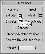
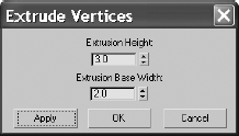
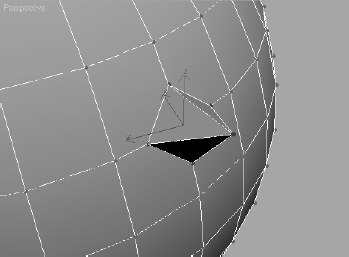
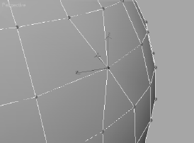
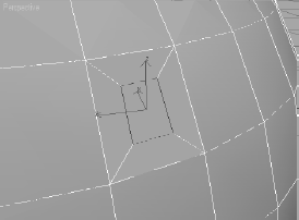
Select a vertex on your sphere. The vertex will turn red. Go to the Edit Vertices rollout in the Modify panel, and press the Settings button (next to Extrude) to bring up the dialog box shown in Figure 4.27. Set an exact extrusion height and base width, and click Apply to create the extrusion. You can also click and drag to interactively pull out the vertex. Figure 4.28 shows a single extruded vertex.
Extrude acts the same in any of the sub-object modes—Vertex, Edge, or Poly. Figure 4.29 shows an extruded edge; you saw what an extruded polygon looks like earlier in the chapter.
You will be able to work with more extrude options in the Creating the Fingers exercise later in this chapter.
In the following steps, you will use a different tool, called Chamfer, to create extra detail on an editable poly:

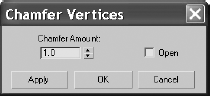
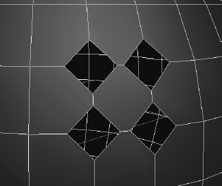
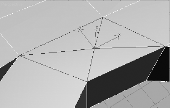
When you chamfer a sub-object, 3ds Max creates new faces around the area you have selected, complete with connecting edges, as you can see in Figure 4.30. Having been offset from the original vertex location, the three vertices are split into four new vertices each and arranged in a diamond formation. Chamfering, in this case, is good for creating some extra area of detail in your mesh or poly.
You can also use Chamfer to cut a hole in your surface. If you click the Open option box in the Chamfer Settings window, 3ds Max will cut a hole where the Chamfer exists, as shown in Figure 4.31.

When you are in the Edge sub-object level, you can chamfer edges. In this case, the chamfer splits an edge into more edges and offsets them from their original location. In Figure 4.32, the corner edge of a box (shown on the right) is selected and chamfered (shown on the left).
Note
Use Chamfer with some caution, because you can create overlapping geometry without realizing it.

Welding vertices helps you combine vertices on a poly or mesh that should occupy the same space. It helps simplify the model by taking out extra vertices that need not be there. Welding also can help shape your model. The following steps show you how to weld vertices together:
Start with a new Editable Poly sphere, in a new scene if you wish. Remember, to get an Editable Poly sphere, create a sphere and convert it to an editable poly by rightclicking on the Sphere entry in the Modifier Stack and selecting Editable Poly.

Use the Weld Threshold spinner in the Weld Settings window to weld the two vertices together, as shown in Figure 4.33. The Weld tool combines selected vertices that are within the threshold you set.
Weld is used a lot when detail is added to a model, such as with a chamfer, and some of the points need to be pulled together and combined into a single point.
You can also click the Settings button next to Bevel to open the Bevel Settings window shown here.
The Outline function allows you to resize a polygon cleanly. Follow these steps to outline a polygon:
With a new Editable Poly sphere, go into Polygon level and select a polygon on the face of the sphere.
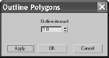
Then click OK or Apply. The polygon will change size, and the edges of the polygons around it will shift to accommodate the newly outlined polygon, as shown in Figure 4.35.
Outline lets you increase or decrease the size of the edges of a polygon. Using Outline is similar to selecting the polygon and scaling it with the Scale tool, but Outline is cleaner and easier to control.
Note
Clicking OK and clicking Apply in a dialog window are not the same. Clicking OK will perform the respective function and close the Settings window. Clicking Apply will perform the action but keep the window open.
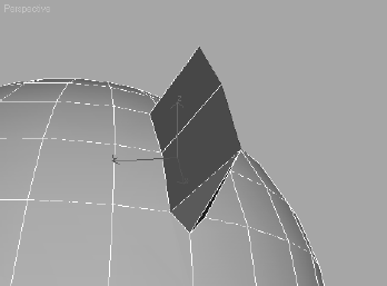
Now let's see some of the more involved tools in the Editable Poly toolset. The Hinge from Edge tool creates a series of new polygons that rotate along an edge on the surface of an existing poly, connecting it to the original object. You can think of it as an extrusion with a rotation.
Follow these steps to see Hinge from Edge in action:
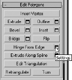
Select a polygon and click the Hinge from Edge button, as shown here, to open the Hinge Polygons from Edge Settings window in Figure 4.37.
Select the edge that will be the hinge or the edge about which the polygons will extrude and rotate. To select the hinge edge, click the Pick Hinge button in the dialog box next to the Current Hinge parameter. Then, in the viewport, go to the selected polygon and choose which edge you want to use.
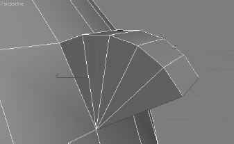
Once you select the hinge, the polygon will hinge out, rotating about that selected edge however many degrees are cited in the Angle parameter. You can use the spinner to select or you can enter the desired angle value for the hinge. The model will interactively hinge the polygon as you set the Angle value. Figure 4.38 shows a small hinge. Notice the hinge is flat, as it only has a Segments value of 1.
In the Settings window, change the Angle value to 90, and the Segments value to 5. Press OK to complete the function. Figure 4.39 shows the results.
The Hinge from Edge tool is an interesting way to extrude, and it can be handy in many instances, such as when you're creating an awning or a curved overhang. Remember, the smoother you need the hinge to be, the more segments you will need to add.


The Cap function creates a new polygon to fill a hole on a surface. For this function, you'll need to be in the Border-level selection. To see a cap in action, follow these steps:
Create a new sphere and convert it to an editable poly.
You may be wondering why you did that. You need to have a hole in the polygon surface for a Cap function and to check out the Border sub-object. As you may recall, a Border-level selection is the row of edges around a hole in a surface or on the edge of a surface, where only one side of the edge has a polygon. In the case of this sphere, the border is the line of edges surrounding the hole.
Now you need to cap the hole. Enter the Border-level selection by pressing the Border icon or pressing 3. Under the Edit Borders rollout, select Cap. The hole should be filled with a single polygon, as shown in Figure 4.40.

This tool can be very convenient. If you have done something to a polygon but don't like it, you can delete that poly and use the Cap tool to create a new one. Keep in mind, however, that cap will use a flat polygon to fill the hole, so a complex surface hole will not be patched with the same surface contours as the original.
Extrude Along Spline
The Extrude Along Spline function works just as it sounds. It will extrude a polygon subobject along a spline path, which is a curve drawn in 3ds Max. Splines will be introduced later in this chapter and covered more extensively in the following chapters.
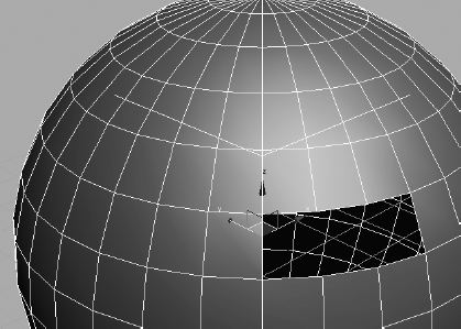
To see the Extrude Along Spline function in action, open the Path Extrude.max file found in the Chapter 4 directory in its Scenes folder. This file has a sphere that has already been converted to an editable poly and a spline that will act as the path of extrusion. To continue, follow these steps:
Select the sphere and go into Poly mode (use shortcut 4, or select the Poly icon in the Modify panel's Selection rollout). Select a polygon; it doesn't matter which one.
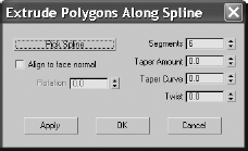
Click the Pick Spline button and click the spline next to the sphere.
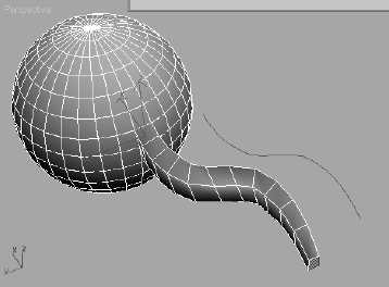
Immediately, you will see an extruded element coming from the sphere. It probably doesn't look very good because you still need to work with the parameters.
Start by adding more segments; 15 to 20 should give you a good-looking extrusion. The extrusion in Figure 4.41 is the result of 11 segments, −0.5 taper amount, and 2.0 taper curve.
Play around with some of the settings to get a good feel for what this tool can do. As a matter of fact, it's a really good idea to play around with all of the tool settings you have seen here and some of the ones you haven't. This is a good way, if not somewhat frustrating, to learn 3ds Max—or any 3D program for that matter. Use this sphere, or another editable poly you create, to experiment with the different tools available in this rollout for all the sub-object levels to get a basic idea of how things work. You can rely on the text in this book, as well as the online user reference dialog titled "Autodesk 3ds Max Reference," which you can launch from 3ds Max's Help menu.
Let's finally put some of your newfound knowledge into practice. If you skipped to this section from the beginning of the chapter or even from the beginning of the book, look at the previous sections in this chapter after you finish this model. Doing so will help fill in some of the gaps in your CG education and better explain how or why you've accomplished some of this exercise's topics.
In this section, you will model a chest of drawers (or dresser) to develop your editablepoly muscles. Why buy a chest of drawers when you can just make one in 3ds Max? Make sure you make it large enough for all your socks.
Ready, Set, Reference!
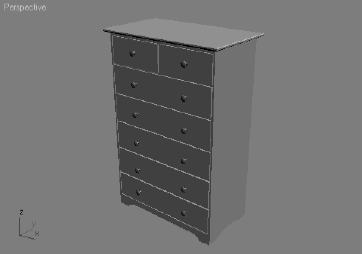
You're so close to modeling something! You'll want to get some sort of reference for what you're modeling. Study the photo in Figure 4.42 for a look at the desired result.
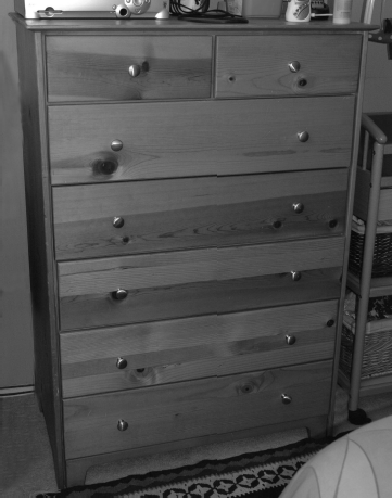
There are plenty of reference photos, and you will access them throughout this exercise to help build different parts of the chest. You may want to flip through the following pages to see the various photos to get a better idea of what you will be modeling.
Of course, if this were your chest of drawers, you could have captured tons of pictures already, right?
Ready, Set, Model!
Note
It's never a good idea to work from a CD. To learn how to create a new project, see Chapter 2, "Your First 3ds Max Animation."
Top of the Dresser
To begin the chest of drawers model, follow these steps:
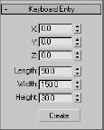
Begin with a new scene (choose File → New, and click New All in the pop-up window). Select the Perspective viewport and enable Edged Faces mode in the view (right-click the viewport name and toggle on Edged Faces from the menu). Go to the Create panel. In the Geometry heading, click Box. You are going to create a box using the Keyboard Entry rollout shown here.

With the box still selected, go to the Modify panel. You can see the box's parameters here. You will need to add more height segments, so change the Height Segs parameter to 6. Your box should look like the box in Figure 4.43.
Add an Editable Poly modifier to the box by selecting the box and choosing Modifiers → Mesh Editing → Edit Poly. As shown in Figure 4.44, you can always go through the Modifier Stack to convert the box to the editable poly instead of using the menus.
Press 4 on your keyboard to take you to the Polygon sub-object mode. Now select the polygon on the top of the box. As you can see in the viewport, the polygon is shaded red when it's selected.
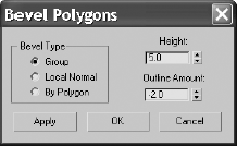
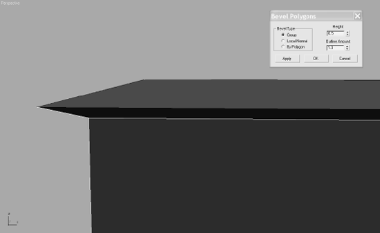
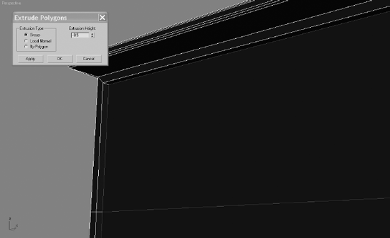
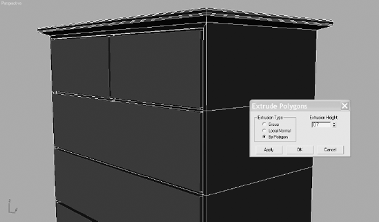
Now go to the Edit Polygons rollout in the Modify panel and select Settings (the button next to Bevel). We are going to bevel several times to create the lip on the crown of the dresser shown in Figure 4.45.
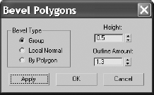
After the first bevel is applied, add more bevels to round out the crown. In the still-open Bevel Polygons window, input these parameters: Height: 0.1 and Outline Amount: 0.06. Click Apply (you want to keep the Bevel window open because you'll need to bevel several times). This will bevel a very slight bit up, as shown in Figure 4.47.
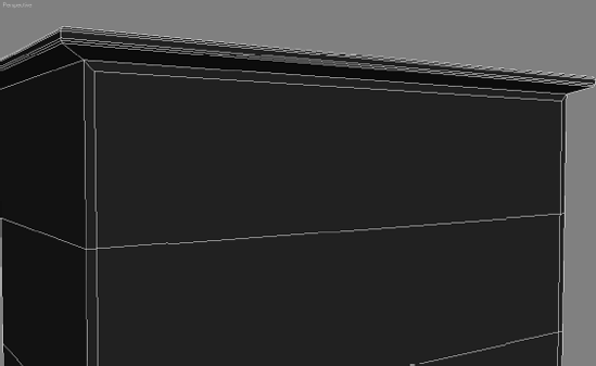
For the third bevel, input the following values: Height: 0.1 and Outline Amount: 0.03. Click Apply. Next, input these values: Height: 0.1 and Outline Amount: 0. Click Apply. This creates a slight curve in the crown. Again enter new values: Height: 0.3 and Outline Amount: 0. Click Apply. For the sixth bevel, change the values: Height: 0.1 and Outline Amount: −0.06. Click Apply. Finally, enter these values: Height: 0.1 and Outline Amount: −0.08. Click OK. Your dresser's top should resemble Figure 4.48 and Figure 4.49.


Bottom of the Dresser
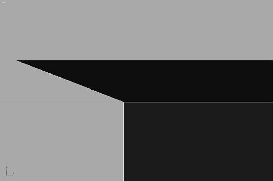
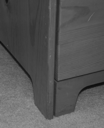
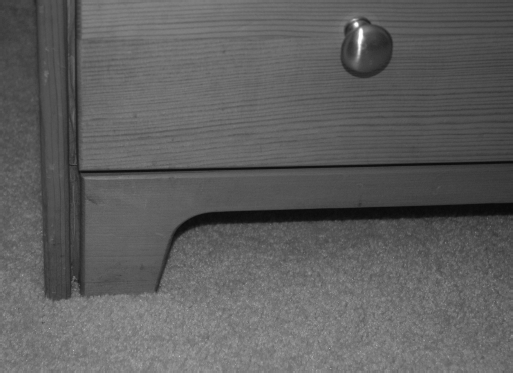
Now it is time for the bottom of the dresser. This dresser doesn't have legs, but it has a nice detail at the bottom nonetheless, as you can see in Figures 4.50 and 4.51. To create this detail, you need to extrude a segment.

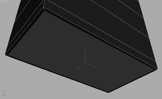
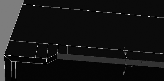
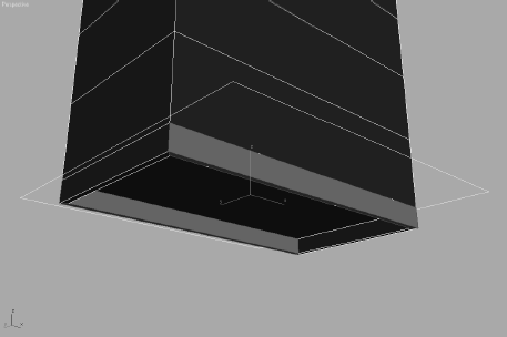
The poly is still selected, so select the Extrude Settings button, enter an Extrusion Height of −2.0, and click OK. Figure 4.53 shows how the bottom of the dresser has moved up into itself slightly.


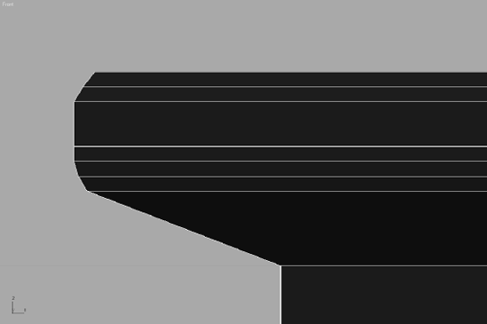
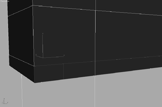
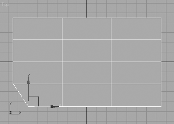
To create the detail on the bottom, you need to add more segments in the newly extruded polygons. Figure 4.54 shows a mock-up of how the bottom lip should be cut. To do this, you will use the Slice tool. The Slice tool works only when the polygons are selected. You will start by slicing into the extruded polygons on the front and back of the bottom lip.
Select all the polygons that make up the front and back lip of the bottom. Make sure you select the front, back, and bottom of the front and back lip as shown in the following graphic. The selections are marked darker in the graphic. It is also a good idea to lock your selection. The Lock icon


Note
The keyboard shortcut for the Selection Lock toggle is the spacebar.

Until now, when you have selected a polygon, it turned solid red in the viewport. You can change it to display as outline when a polygon is selected, and not as solid red. You will need to do this so you can see the new edges you are creating. To turn off Shaded Edge mode, press F2. Your selected polygons will now show red only around the edges.
With the Slice Plane tool still active, right-click in the viewport to bring up the Quad menu. Go to the Transform menu and select Rotate. Figure 4.56 shows this shortcut for the Transform tools.
You need to rotate the Slice Plane gizmo 90 degrees along the Y-axis. Center the cursor over the Transform gizmo's Y-axis (green wire), and click/drag until the Transform type-in box at the bottom of the interface reads 90 in the Y-box, or enter the rotation amount for Y and press Enter. As you rotate, you will see the slice interactively displayed as a red line on the selected polygons.
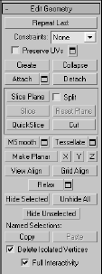
Use the Move tool (W) to position the Slice Plane gizmo where you want the first slice. The movement will be along the X-axis or horizontal along the box. When the Slice Plane gizmo is positioned as shown in Figure 4.57, go to the Edit Geometry rollout and click Slice. Don't click Slice plane because that will deactivate only the Slice Plane tool. You must click the Slice button because it is like clicking an Apply button for the Slice Plane tool. Once you click Slice, the polygon will have a new segment at that location. The Slice Plane tool should still be active.
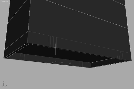
You need four slices at each end of the dresser bottom, as shown in Figure 4.58. Keep in mind that the polygons are selected on the front and back so that the Slice Plane tool will slice only polygons that are selected within the gizmo. Click the Slice Plane button to deactivate the tool when you have placed four vertical slices in all four corners of the front and back bottom lips of the dresser, as shown in Figure 4.58.
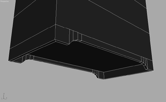
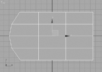
Press the spacebar to unlock your selection. You are going to use a combination of moving edges and polygons to create the detail on the bottom of the dresser as shown here.

Select the relevant polygons, and use the Move tool to place them as shown in Figure 4.59.
Don't worry if your adjustments don't have a perfectly smooth curve. Unless the camera is right on top of the detail, it will look good from a distance. A perfect curve is not necessary, especially for our purposes.
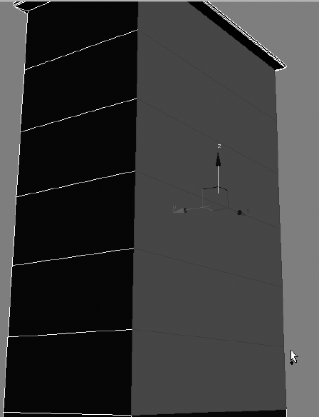
You can use the same techniques in the steps 1 through 8 to create detail in the side bottom lip of the dresser, as shown in Figure 4.60. Make sure you save your work.

I Can See Your Drawers
In the beginning of this exercise, you created a box with six segments on its height. You can use those segments to create the drawers. This is an example of thinking ahead and planning your model before you start an object. This was by far the easiest way to go; using the Slice Plane tool to add segments for the drawers after the box is made is doable, but much more laborious.
For simplicity's sake, you will not create drawers that can open and shut in this exercise. If this dresser were to be used in an animation in which the drawers would be opened, you would make them differently.
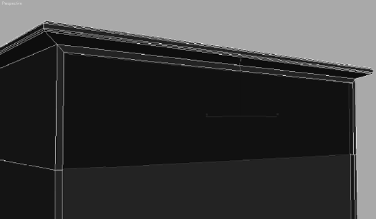
First, take a look at the drawers and see where you have to go. Figure 4.61 shows the drawers and an important detail we need to consider. Luckily, you needn't worry about the junk on top of the dresser.

To model the drawers, begin with these steps:
Create a small gap around the edge of the box. This gap will represent the space between the drawer and the main body of the dresser (Figure 4.61). Go to Polygon mode (press 4), and select the six polygons on the front of the box that represent the drawers. Remember to hold the Ctrl key while selecting the additional polygons; this will allow you to make multiple polygon selections, as shown.


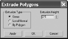
Keep those newly inset polygons selected, and go back to the Edit Polygons rollout to select the Extrude Settings button. Change the Extrusion Height to −0.5, keep Extrusion Type set to Group, and press OK. The faces will now extrude inward a little bit, as shown here.
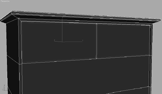
In the original reference picture (Figure 4.42), the top drawer of the dresser is split into two, so you need to slice that top-drawer polygon vertically to create two drawers. Make sure the selected polygons are displayed with the red outlines instead of the solid red color (you can toggle between these views with the F2 key). Switch your viewport to a front view.
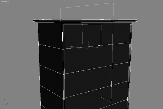
Select the polygon that represents the top drawer, as shown in Figure 4.63. Select Slice Plane in the Edit Geometry rollout. Rotate and move the Slice Plane gizmo so that it is vertical and centered on the polygon as shown here, and click Slice. Click the Slice Plane button to release the tool.
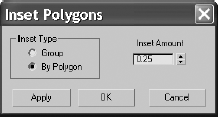
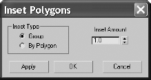
This setting insets each polygon individually, instead of performing this operation on multiple, contiguous polygons (which is what the Group option does). Click OK to run the Inset operation. Your polygons should resemble the ones in Figure 4.64.
Perform the same inset operation on the remaining drawer polygons on the front of the box (as shown): Set the Inset Amount to .25, and set the Inset Type to By Polygon. This will inset the five lower, wide drawers.
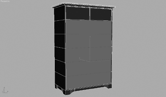
Select all of the "drawer" polygons. Go to the Edit Polygons rollout and click Extrude Settings. Set the Extrude Amount to 0.7 as shown here. You don't need it to extrude very much; you just want the drawers to extrude a bit more than the body of the dresser.
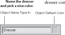
Go grab yourself a frosty beverage! The dresser is finished. Go ahead and name the dresser. You can even change the color of the dresser if you'd like. Go to the Name and Color type-in box (shown in Figure 4.65), change the name of the object to Dresser, and pick a nice light color.
Creating the Knobs
Now that the body of the dresser is done, it's time to add the final bit of detail to make the dresser complete: knobs. We will use Splines and a few surface creation tools new to your workflow. Goose bumps, anyone? Take a look at the reference for the knobs in Figure 4.67. You are going to create a profile of the knob and then rotate the profile around its axis to form a surface. This technique is known as Lathe, not to be mistaken for latte, which is a whole different deal and not really covered in this book.
Here's a quick rundown of what a spline is. A spline is a group of vertices and connecting segments that form a line or curve. To create the knob profile, we are going to use the Line Spline, shaped in the outline of—you guessed it—a knob. The Line tool allows you to create a free-form spline.


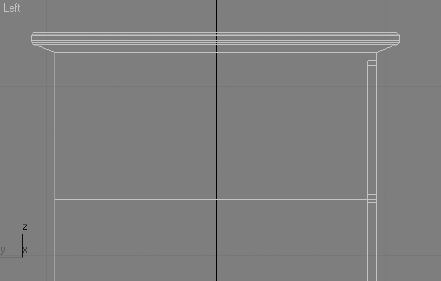
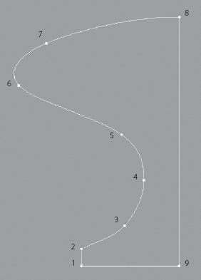
Make sure you are in the Left viewport, so you can see which side of the dresser the drawers are on, as shown here. You are going to create a profile of half the knob, as shown in Figure 4.68. Don't worry about creating all the detail in the knob because detail won't be seen; a simple outline will be fine.
Go to the Create panel and choose Shapes

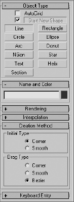
Figure 4.69 shows the profile line with the vertices numbered according to their creation order.
Note
To create a straight line segment between two vertices, press and hold Shift to keep the next vertex to be laid down orthogonal to the last vertex, either horizontally or vertically.
Once you lay down your last vertex at the top, finish the spline by either right-clicking to release the Line tool or clicking the first vertex you created to close the spline. For this example, it really doesn't matter which method you choose. Either an open or closed spline will work; however, a closed spline is shown in Figure 4.69. Drawing splines entails a bit of a learning curve, so it might be helpful to delete the one you did first and try again for the practice. Once you get something resembling the spline in Figure 4.69, you can edit it. Don't drive yourself crazy; just get the spline as close as you can.
Note
When you are creating a line, you can click once to create a corner vertex for the line, but you need to click and drag to create a Bezier vertex if you want to put a curve into the line.

A LINE'S VERTEX TYPE
When you center your cursor over a line's vertex and right-click to bring up the shortcut menu shown, you will have access to several vertex controls. In that shortcut menu, under the Tools1 heading, you can choose a vertex type.
The vertex types are the following:
Smooth: A Smooth vertex creates a smooth continuous curve. The actual curvature at a smooth vertex depends on the spacing of the adjacent vertices. This is a nonadjustable vertex, meaning it has no handles with which you can control the curvature directly.
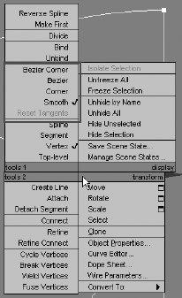
Corner: A Corner vertex is nonadjustable, which creates sharp corners.
Bezier: A Bezier vertex is a vertex that has locked continuous handles that create a smooth curve. You can directly adjust the curvature at a Bezier vertex by manipulating its handles. Adjusting a handle on one side of the vertex will also adjust the other side's handle, as they are continuous.
Bezier Corner: A Bezier Corner vertex creates a sharp corner like the Corner vertex, but it has discontinuous tangent handles with which you can control the curvature of the line at that vertex. The handle on one side of the vertex will not affect the handle on the other side.
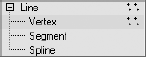
In some ways, Line's sub-objects are similar to the Editable Poly sub-object modes. However, when you are working with a spline, you are working with a 2D nonrendering object. A spline is made up of three sub-objects: a vertex, a segment, and a spline. As you know, a vertex is a point in space. A segment is the line that connects two vertices. The Spline mode allows you to select and/or transform a single or multiple splines within a spline object. To continue with the project, follow these steps:
Choose the vertex sub-object for the line. Make sure you are still working in the Left viewport. When you're working with 2D splines, it is always best to work in Orthographic view. Use the Move tool to click on one of the vertices. The vertex has a Transform gizmo just like an object. Use the Move tool to edit the shape to better fit the outline of the knob.
Be sure to read the sidebar in this section entitled "A Line's Vertex Type" to learn more about the types of vertices a line can have and how it can change the curvature of a line. If needed, you can change the vertex type of your line's vertices to control the curvature.

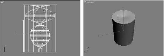
The profile line is ready to turn into a 3D object. This is where the modifiers are used. Get out of sub-object mode for your line. Choose Modifiers → Patch/Spline Editing → Lathe. (You could also go to the Modifier List and choose Lathe from the alphabetical list of modifiers.) When you first put the Lathe modifier on your spline, it won't look anything like the knob (see Figure 4.70)—but don't panic! You need to futz with the parameters to get it right (Figure 4.71). Right now the object is turned inside out.
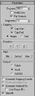
Go to the Parameters rollout and under the
Alignheading click the Max button. It's a knob! Now, that is more like it. You just had to change the alignment of the axis so the lathe revolution would be correct.Note
If step 3 does not work properly for you, try clicking Min instead of Max under the Align heading. When you are creating a line, where you begin to create that line and in what order you place the vertices (clockwise or counterclockwise) are both important. This example drew the knob's profile line in a clockwise direction.
Rotate the perspective view so you can see the top of the knob. You should notice a strange artifact. To correct this, check the Weld Core box under the Parameters rollout for the lathe.
That's it! Check out Figure 4.72 for a look at the lathed knob. By using Splines and Lathe, you can create all sorts of surfaces for your models. In the next section, you will resize the knob, position it, and copy it to fit on the drawers.
Copying the Knob
Now that you have a knob, you may need to adjust it and make it the right size. If you still want to futz with the knob, go back down the stack to the line to edit your spline. For example, you may want to scale the knob a bit to better fit the drawer (refer to the reference photo in Figure 4.67). Select the Scale tool, and click and drag until the original line is about 40 percent smaller. The Lathe modifier will re-create the surface to fit the new size. You can also delete the knob and restart with another line for more practice. In the following steps, you will copy and position the knob for the drawers.

Position and rotate the knob to fit on to the front of a top drawer. Change its default color (if you want) and change its name to Knob.
You'll need a few copies of the original knob, one for each drawer. Choose Edit → Clone (Figure 4.73). You are going to use the Instance command. An instance is a copy, but is still connected to the original. If you edit the original or an instance, all of the instances change. Click OK to create an instance.
Position the instanced knob in the middle of the other top drawer.
Using additional instances of the original knob, place knobs in the middle of all the remaining drawers of your dresser, as shown in Figure 4.74.

As you saw with this exercise, there are plenty of tools for the Editable Poly object. Your model doesn't have to be all of the same type of modeling either. In this example, we created the dresser with box modeling techniques, where you begin with a single box and extrude your way into a model, and with surface creation techniques using splines.
Now that you've had some experience modeling in 3ds Max, you can tackle modeling a simple hand. The goal is to acquire experience with some other tools 3ds Max has to offer. Before you begin modeling, look at a reference. Luckily, you probably have one or two hands at the ends of your arms.
Note
If you have access to Introducing Maya 2008: 3d for Beginners, by this volume's author, you can also reference a similar hand modeling tutorial to see how modeling workflows compare between 3ds Max and Maya.
Starting the Palm
There are several ways to model a hand, but you'll start with the same modeling techniques you started with in the Dresser exercise. To begin box-modeling the hand, follow these steps:
Start a new 3ds Max file in a new project called Hand, or copy the Hand project from the companion CD to your hard drive.
Go to the Modify panel, and you will see the parameters for the box. You need to subdivide the box so it has more polygons. Press F4 to toggle on Edged Face mode in your viewport. In the Modify panel's Parameters rollout, set the box's Length Segs to 4, Width Segs to 3, and Height Segs to 1, as you see here.

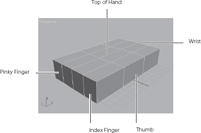
Look at the box and imagine that it is the palm of the hand. The polygons facing you in Figure 4.75 are going to be the fingers. The poly farthest from you will be the pinky finger, and the one nearest will be the index. This should help you get oriented.
Convert the box into an Editable Poly object (not the Edit Poly modifier). You can reference the Dresser exercise in this chapter if you have skipped to this section.
The fingers' polygons will need to be slightly splayed out, so they will not all stick together when you extrude them. Use the Edge sub-object mode to do this. In the Modifier Stack, click the plus (+) sign to reveal the sub-objects for the box.
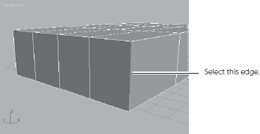
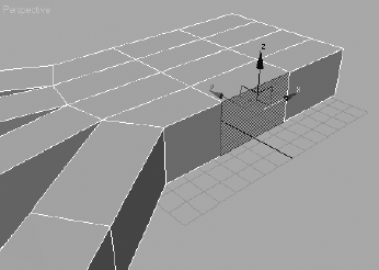
Use the keyboard shortcut 2 to choose the Edge sub-object level. Select the edge closest to you (which will be the outer edge of the index finger), as shown in Figure 4.76.
Click the Lock Selection icon (

Use the keyboard shortcut Wto enable the Move tool. Move the edge along the X-axis. You might find it easier to use the Top viewport for the move. Use the Transform gizmo—center the pointer so that the X and the tail of the X-axis arrow are yellow.
Yellow indicates that the axis is active. This will confine the movement to the X-axis and no other, as shown here.

Switch to the Top viewport and move the edge, as shown here. Press the spacebar to release the selection Lock.
Move the other edges to create a slight arch where the top of the palm will be, as shown in the following graphic. This will ensure that when you extrude the polygons for the fingers, there will be space for the webbing in-between. If you don't want the fingers spread apart this much, make the arc less curved. This repositions the polygon to a different angle so it won't extrude straight
Creating the Fingers
Now it is time to extrude the fingers.
With the box selected, select the Polygon sub-object mode or press 4 on your keyboard. Go to the perspective view. Click on the polygon that represents the index finger (closest to you), as you see here.

Go to the Modify panel under the Edit Polygons rollout. Click the Extrude Settings button (

EXTRUDE OPTIONS
Using the palm model of the hand for reference, the options for an extrude operation will behave as indicated here. All of the polygons on the front of the box are selected:
Group—The polygons are extruded out along their averaged normals, effectively extending the palm out, as shown here
Local Normal—The polygons are extruded straight out along their normal (usually perpendicular to the polygon's face), creating a flare at the end of the palm
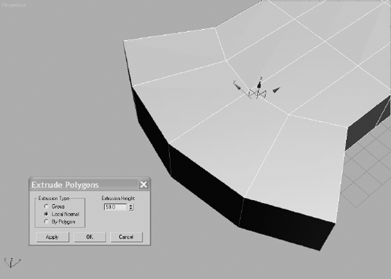
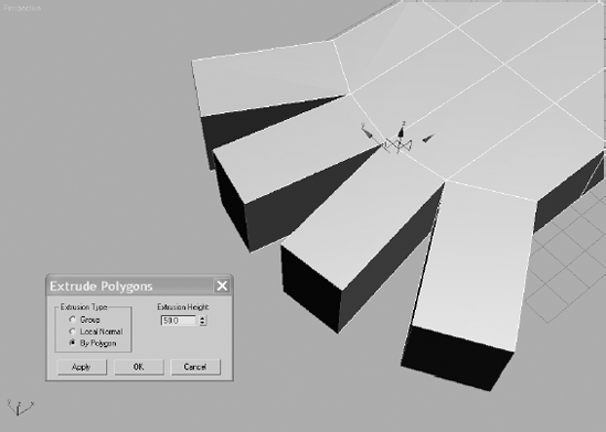
By Polygon—Each polygon is extruded individually along its own normal
Extrusion Height—Specifies how much to extrude in scene units. As you've already seen, positive values extrude out away from the object, and negative values extrude into the object.
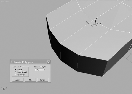
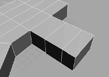
We are going to extrude the first finger so that it has three sections, so instead of doing one extrude, we are going to do three back to back. This will give the finger more segments with which to work. If you look at your own finger, you will notice the lower joint is the biggest joint, getting smaller toward the tip of the finger. In the Settings dialog box, set the first amount to 60. The Setting dialog box allows you to interactively perform these functions so you can see the extrude before you apply it. The 60-unit extrude looks good, so click Apply. This keeps the Settings window open. Go to Extrusion Amount and enter 50; this will change the extruded segment to 50 units. Click Apply again for the second extrusion. Change the extrude amount to 40, and press OK for the last extrusion of the index finger. Figure 4.78 shows the first finger.
Using the same techniques and the following settings for the extrusion amounts, extrude the rest of the fingers.
F I N G E R | F I R S T E X T R U D E | S E C O N D E X T R U D E | T H I R D E X T R U D E |
|---|---|---|---|
Middle Finger | 70 | 60 | 50 |
Ring Finger | 60 | 50 | 40 |
Pinky | 50 | 40 | 30 |
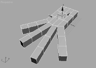
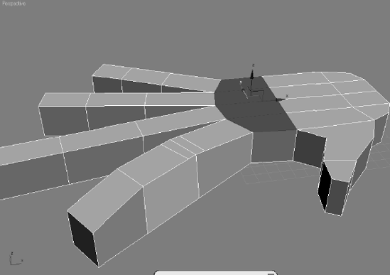
Figure 4.79 shows all the fingers extruded. You can use other values as long as you have three segments in each finger. Use your own hand as a guide.
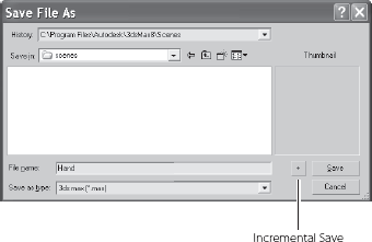
This is a good time to do another Save As; make sure you use the plus sign (+) instead of pressing the Save button. To catch up to this point or to check your own work, load the scene file Hand02.max from the Hand project on the companion CD.
Creating the Thumb
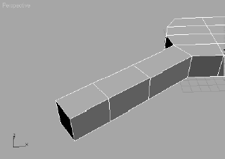
Now you will create the thumb, also using extrusions. Follow these steps:
Select the polygon in the middle of the side of the hand, as shown here
As with the fingers, the thumb will have three segments. Select the Extrude Settings button and enter an extrude amount of 30. With the value of 30, click Apply twice for two 30-unit extrusions. Now enter an extrude amount of 20 and click once more. Click OK. Figure 4.80.
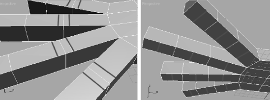
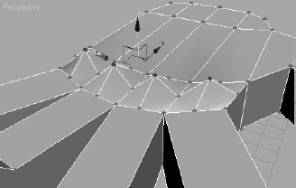
To shape the thumb, you will use a combination of adjusting edge and poly locations. Figure 4.81 shows a picture of a hand; notice how the thumb extrudes from the bottom of the hand. Using Edge mode, rearrange the edges in the extruded thumb to create a shape as shown in Figure 4.82.


You may be wondering how to take this boxy thing and turn it into something more organic and realistic. By using Subdivision Surfaces (SubDs), you can take a relatively simple object with very few segments and subdivide the polygons. SubDs make a flat surface appear smoother.
Follow these steps to use Subdivision Surfaces for your hand:
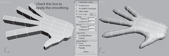
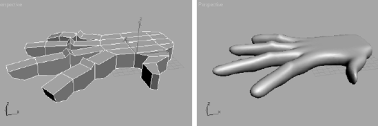
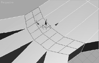
To apply the SubD, with the hand selected, check the Use NURMS Subdivision box in the Subdivision Surface rollout in the Modify panel. Figure 4.83 shows the hand before and after you apply the NURMS Subdivision.
Once the smoothing is applied, you will see an orange cage surrounding the hand if you are in any sub-object mode, as shown here. This allows you to work with this low-res cage while the smoother version is updating at the same time

You can control how much smoothing applies to the hand using the Iterations parameter, which is by default set to 1. Be very careful how many iterations you add. The higher the number, the harder the computer has to work to process the information. You can leave Iterations set to 1 for the hand.
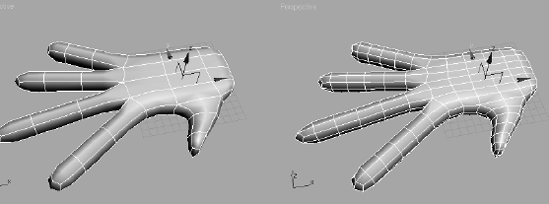
Uncheck Isoline Display in the Subdivision Surface rollout. When Isoline Display is off, 3ds Max displays all the faces added by the smoothing, as shown on the right in Figure 4.84. The default setting of On shows only the object's original edges, as shown on the left in Figure 4.84.
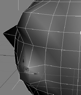
Make sure you are in Polygon sub-object mode. Press F2 to toggle the Shaded Face mode, so that when you select a poly, it will be shaded in red and easier to see. Now, select a polygon on the hand and right-click to access the shortcuts menu. Select Transform → Move. Move the polygon in any direction. The polygon will pull the surrounding polygons with it, but the selection is softer (Figure 4.85). This makes it possible to model in a push and pull fashion, just as if molding clay.
You don't want to save what you have done with the SubDs, so either undo all the smoothing changes or reopen the last saved file. You will probably find it easier to work with the boxy hand before the NURMS smoothing. You can also just uncheck the Use NURMS Subdivision. You will come back to this later.
Adding Detail to the Hand

The Cut tool allows you to divide an edge at any point. You then divide a second edge at any point, and the tool will create a new edge between the two points. To create more edges for detail on the hand, follow these steps:
With the hand selected, click the Cut Tool button. Now click the first edge (use Figure 4.86 as a reference) at the first knuckle on the index finger. A new vertex is created where you clicked. A dotted line will track along with your cursor until you click a second edge.
Click the opposite edge from your initial one to add a new edge next to the first segment on the index finger. Right-click to exit the tool.
Using the same sequence of commands, add new edges to the knuckle areas shown in Figure 4.86. You may want to add the new edges in a Nonperspective viewport.
Note
Working with the Cut tool in a Perspective viewport may be a bit difficult; the newly created edges may appear to jump around the hand or won't place correctly. In the Orthogonal views, it is simpler to read where the Cut tool is placing edges. With the Cut tool, you can cut across any number of faces. Also, if you double-click on the first edge, 3ds Max will divide that edge at the point where you clicked by adding a vertex there. You need not click on a second edge if you double-click.
Right-click to exit the tool.
Note
While working with the Cut tool, turn on Ignore Backfacing in the Selection rollout to avoid selecting edges on the back of the hand by accident.
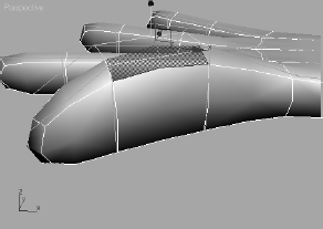
With all the new edges, use the Move tool to move those edges to create the knuckles and the fleshy area on the bottom of the fingers. You can also rearrange the edges at the tip of the finger to give the fingers a more tapered look. Click on Use NURMS Subdivision to see how the knuckles and fingers look with smoothing, as shown in Figure 4.87. You can see how the NURMS SubDs really smooth out the detail; so don't be afraid to exaggerate the detail so that it looks better when smoothed, as you can see on the right in Figure 4.87. Deselect Use NURMS Subdivision to return to the boxy hand.
Let's add some knuckles at the end of the fingers. You are going to use a tool for adding detail that is another way of subdividing a polygon. Tessellate doesn't give you the control options the Cut tool does, but it can be more precise. The Tessellate button is under the Edit Geometry rollout in the Modify panel. Two Tessellate methods are available: Edge and Face (Figure 4.88).

See the sidebar in this section titled "Tessellate Options" for more on Tessellate before you use it in the following steps.
Continue with these steps to add detail with the Tessellate function:
Before you tessellate any of the polygons on the hand, edit the poly size. The polygons are too long and they should be squarer. Select the lower edge of the polygons and move them closer to the base of the fingers, as you can see in Figure 4.89.
TESSELLATE OPTIONS
Edge—Vertices are inserted in the middle of each edge of the selected polygon, and a line is drawn connecting the new vertices to form new edges inside that polygon. The number of new polygons will be equal to the number of sides on the original polygon

Face—A vertex is inserted into the middle of the selected polygon, and edges are drawn from the original vertices of the polygon to the new vertex. Again, the number of new polygons will be equal to the number of sides on the original polygon
Tension—This parameter controls the Edge tension value, which essentially pulls vertices inward or outward from the plane, creating a concave or rounding effect, respectively. You can see how the edge is concave in this graphic
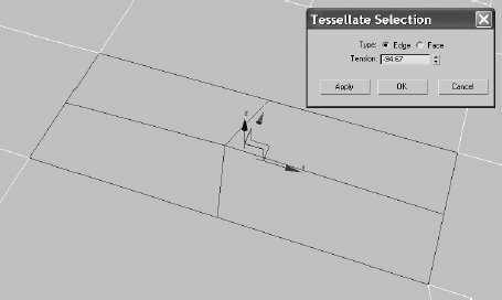
Select the polygons at the base of the fingers and hold the Ctrl key down, which will allow you to select all four polygons, as shown in Figure 4.90. Select the Tessellate Settings button under the Edit Geometry rollout. You are going to use the Edge option with Tension set to 0. Click OK, and your hand should tessellate as in Figure 4.91.
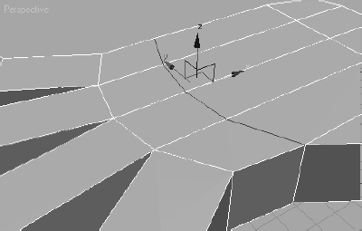
Switch to Vertex mode and select the vertices in the center of the subdivided polygons. Right-click to access the shortcut menu and choose Move. Move the vertices up away from the hand along the Z-axis, as shown in Figure 4.92. Check the Use NURMS Subdivision box to see the smoothing of the hand with the raised knuckles (as shown in Figure 4.93). You may want to go back to Vertex mode while in NURMS to use the SubDs cage to refine the changes. Continue to edit until you are satisfied with the look. Don't forget to save another iteration.
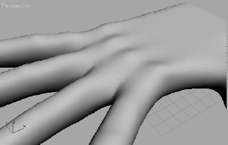
Now that you have created the basic shape for the hand, you should use the NURMS cage to refine and edit the look. Remember you have to be in a sub-object mode for the cage to appear.
To check your work, load the scene file Hand04.max from the Hand project on the companion CD.
Don't bog yourself down trying to model small details such as knuckle wrinkles or lines on the palm. Those details can be added using materials in texturing.
In this chapter, you learned how to model with 3ds Max. Through exploring the modeling toolsets to creating a dresser and a hand, you saw firsthand how the primary modeling tools in 3ds Max operate.
You began by first examining how to best plan a model. Then you learned some modeling concepts and how to use modifiers and the Modifier Stack effectively. You moved on to learning the differences between objects and meshes, and how to use sub-objects to edit your surfaces before you began a series of short exercises describing some of the poly editing tools. With that under your belt, you learned how to put these tools to use by making a dresser and finally modeling a simple hand.
Modeling is an artful craft. It is best to know where you are trying to go in your mind's eye, so you can effectively get there with your models. Becoming a good modeler takes time and patience; so stick with it.