
Light is everything. By light we see, and by light we show. Light shapes the world around us and defines shape, color, and texture. Computer graphics hang on every word light has to whisper. Without faithful lighting, any good computer graphic will fall to its knees and fail. Lighting is the most important aspect of CG, and it just simply cannot be mastered at a snap of the fingers. The trick to correctly lighting a CG is understanding how light works and seeing the visual nuances it has to offer.
In this chapter, you will study the various tools used to light in 3ds Max. This chapter will serve as a primer to this most important aspect of CG. It will start you on the path by showing you the tools available and giving you opportunities to begin using them.
Topics in this chapter include:
Basic Lighting Concepts
Three-Point Lighting
3ds Max Lights
Common Light Parameters
Ambient Light
Lighting the Red Rocket
Creating Shadows
Atmospheres and Effects
Light Lister
On a conceptual level, the lighting in 3ds Max mimics the real-world direct-lighting techniques used in photography and filmmaking. Lights of various types are placed around a scene to illuminate the subjects as they would for a still life or a portrait. Your scene and what's in it dictate, to some degree at least, which lights you put where. A number of considerations must be kept in mind when settling on a methodology and light types for CG, but the overall concept of lighting is strikingly similar between a real-world set lighting and CG.
At the basic level, you want your lights to illuminate the scene. Without lights, your cameras have nothing to capture. Although it seems rather easy to throw your lights in, turn them all on, and render the scene, that couldn't be further from the truth.
Lighting is the backbone of CG. Although it is technically easy to insert and configure lights, it is how you light that will make or break your scene. That skill really only comes with a good deal of experience and experimentation, and it requires a good eye and some patience.
In this chapter, you will learn the basic procedures for lighting a scene in 3ds Max. No single chapter could explain everything about lighting, and no beginner or intermediate CG student should expect to quickly master the art of lighting CG. In short, lighting touches every single aspect of the CG pipeline. A strong lighter understands modeling form and is able to make adjustments to enable efficient lighting. Lighters understand motion and how to light for it. They understand textures and materials, and they frequently are tasked with creating or adjusting materials to work perfectly with their lights. Strong lighters are also rendering experts. When it's time to render, they must know what is and is not doable in a scene. They must diagnose problems and overcome obstacles to make sure every frame is rendered faithfully and with artistic merit.
Develop Your Eye
As corny as it sounds, to be an artist, you must learn to see. This is especially true for CG lighting. There are so many nuances to the real-world lighting around us that we take them for granted. We intuitively understand what we see and how it's lit, and we infer a tremendous amount of visual information without much consideration. With CG lighting, you must re-create these nuances for your scene. That amounts to the work of lighting.
The most valuable thing you can do to improve your lighting technique is to relearn how you see your environment. Simply put, you must refuse to take for granted what you see. If you question why things look the way they do, you'll find that the answers almost always come around to lighting.
Take note of the distinction between light and dark in the room you're in now. Notice the difference in the brightness of highlights and how they dissipate into diffused light and then into shadow.
When you start understanding how real light affects objects, you'll be much better equipped to generate your own light. After all, the key to good lighting starts with the desire to simply create an interesting image.
Your Scene and Its Needs
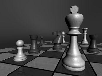
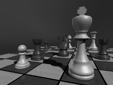
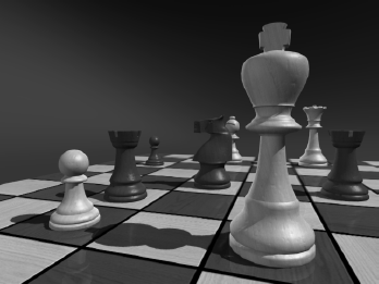
Your scene needs a careful balance of light and dark. Too much light will flatten your image and lose details in form. This is the first mistake many beginners make; they tend to over-light to make sure everything is lit. Figure 10.1 is a rendering of a chessboard that has too many bright lights. The lighting only flattens the image and removes any sense of depth and color.
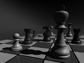
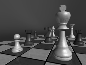
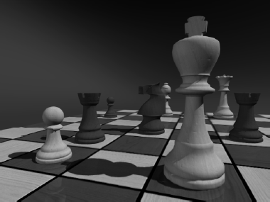
On the other hand, under-lighting a scene will make it muddy and gray and pretty lifeless. Your details will end up covered in darkness, and everything will flatten out as well. Figure 10.2 shows you the same chessboard that is under-lit. You hardly notice the details in the mesh.
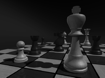
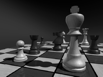
Your first job as a lighter is to find the balance between over-lighting and under-lighting. It sounds simple, and it is—although it requires lighting a shot several times and test rendering it to check the outcome. Like a photographer, you want your image to have the full range of exposure. You want the richest blacks and the brightest whites in your frame to give it a deep sense of detail. Figure 10.3 shows you a fairly well-balanced lighting for the same chessboard. The light and shadow complement each other, and the lighting works to show off the features of the objects in the scene.


Three-point lighting is a traditional approach to lighting a television shot. After all these years, the concepts still carry over to CG lighting. In this setup, three distinct roles are used to light the subject of a shot. More than one light can be used for each of the three roles, but the scene should in effect seem to have only one primary or key light, a softer light to fill the scene, and a back light to make the subject pop out from the background.
This does not mean there are only three lights in the scene. Three-point lighting suggests that there are three primary angles of light for your shot, dependent on where the camera is located.
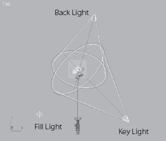
Three-point lighting ensures that your scene's main subject is well lit and has highlights and a sense of lighting direction using shadow and tone. Figure 10.4 shows you a plan view of the threepoint lighting layout. The subject is in the middle of the image.
Key Light
A key light is placed in front of the subject for the primary light. The key is placed off to one side to give a sense of direction to the light, because one side will be brighter than the other. Shadows will fall from this light to heighten the sense of direction and increase the depth of the shot.
Although it is possible for several lights to fulfill the role of key light in a scene—for example, three overhead ceiling lights—one light should dominate, creating a definitive direction. Figure 10.5 shows the subject being lit by a single key light.
Here, the key light produces a moody still life. It may be composed of more than one 3ds Max light, although the intent would be that all the lights that comprise the key should come from roughly the same angle.
Fill Light
A more diffused light than the key light, the fill light seems directionless and evenly spread across the subject's dark side. This fills the rest of the subject with light and decreases the dark area caused by the key light.
The fill light shouldn't necessarily cast any shadows onto the subject or the background. In fact, the fill light is actually used to help bring up the darkness and soften the shadows created by the key light. Figure 10.6 shows the same still life with an added fill light in the scene. The fill light clearly softens the shadows and illuminates the dark areas that the key light misses by design.
In most cases, you'll need to place the fill light in front of the subject. The fill, however, is aimed so that it shines from the reverse side of the key light. This angle intentionally targets the dark side of the subject. Even though the still life in Figure 10.6 is still a fairly moody composition, much more is visible than with only the key light in Figure 10.5.
Back Light
The back light, also called a rim light, is placed behind the subject to create a bit of a halo, which helps make the subject pop out in the shot. As a result, the subject has more presence against its background. Figure 10.7 shows how helpful a back light can be.
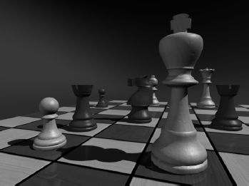

The back light brings the chess pieces out from the background and adds some highlights to the edges, making the composition more focused.
Don't confuse the back light with the background light, which lights the environment behind the subject.
Three-Point Lighting in Action
The focus of a three-point lighting system is the primary subject of the shot. This means the lighting is based on the position and angle of the subject to the camera. When a camera is moved for a different shot, even within a scene of the same subject, a new lighting setup is more than likely required. This makes three-point lighting shot-specific and not scene-specific. Of course, once you have a shot set up with the lighting you like, changing it slightly to suit a new camera angle is much easier than starting from scratch.
When the lighting is completed for the subject of a shot, the background will probably need to be lit as well. For the background, you would typically use a directed primary light source that matches the direction of the key light. This becomes your background's main light. Then you would use a softer fill light to light the rest of the background scene and to soften the primary shadows.
Practical Lighting
Practical lighting is a theatrical term describing any lights in a scene that are cast from lighting objects within the scene. For example, a shaded lamp on a nightstand in the background of a scene set in a bedroom would need practical lighting when the light is turned on. The practical lighting shouldn't interfere with the main lighting of the scene, although if the scene's lighting is explicitly coming from such a source, you will have to set up your key light to match the direction and general mood of the practical light in the shot.
Not every light-emitting object in your CG scene automatically calls for its own light in 3ds Max. Rendering tricks such as glow often are used to simulate the effect of an active scene light. This way, you don't need to actually use a 3ds Max light. Of course, if you need the practical light to illuminate something in the scene, you need to create a light for it.
3ds Max has two types of light objects: photometric and standard. Photometric lights are lights that possess very specific features to enable a more accurate definition of lighting, as you would see in the real world. Photometric lights have physically based intensity values that closely mimic the behavior of real light. They are rather advanced and will not be covered in this book.
Standard lights are still extremely powerful and capable of realism, but they are more straightforward to use than photometric lights and less taxing on the system at render time.
Note
Default Light
What happens if you have no lights at all in your 3ds Max scene? In this case, the scene is automatically lit by default lighting. When you add light objects, the default lighting is replaced entirely by the new lights. There is very little you can do with the default lighting; it is there for your convenience so you easily can view an object in Shaded mode and test render without creating a light first.

One or Two Default Lights
When you use default lighting, there is only one light. However, you can customize the configuration so that you can have two lights for default lighting.
To change to two default lights, in the main menu bar choose Customize → Viewport Configuration. In the Rendering Method tab, you can choose whether you want one light or two lights in your default lights under the Rendering Options heading. Figure 10.8 shows the Viewport Configuration's Rendering Method tab.

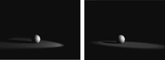
In a single default light, you have a single key light. This light is linked to the viewport, and it moves with the point of view. Setting up the default lighting to have two lights adds a single fill light that is placed opposite the key light. The key is always placed in front of the scene's object being viewed, on its upper-left side. The default fill light, if added, is created behind the object and to the lower right. The link between the default light and the viewport is broken when you have two default lights. In the above images (Figure 10.9), there is a sphere on the left with a single default light. The same sphere is in the middle with two default lights. In the image on the right, the two default lights are no longer connected to the viewport.
In Figures 10.10 and 10.11, you can see how the second default fill light works for the chessboard. Figure 10.10 has the single default light, and Figure 10.11 has two default lights. You can see the addition of a second set of highlights on the chess pieces in Figure 10.11 due to the added fill light.
Converting Default Lights
Remember that the default lights have no parameters and cannot be edited. You can, however, convert the default lighting into light objects that can be edited. To do this, the 2 Lights default lighting option must be selected in the Viewport Configuration.
3ds Max will bring the default lights in as Omni lights (which you will learn about soon). Once you add the default lights, you can edit them like any other light. However, it's always best to just begin lighting the scene with your own lights created from scratch.
Using Default Lights
Once you add a light, any default lighting that has not been added to the scene will be removed. Likewise, if you remove all the lights in a scene, 3ds Max will re-create the default lighting. Figure 10.12 shows the two default lights inserted as Omni lights (the diamond shapes) in the sphere's scene.
Use default lighting as a temporary solution. It gives you an easy way to have a constant light that travels with the viewport's point of view—provided it's the single default light. This helps you see the detail in your modeling, animation, and texturing without having to worry about creating and placing lights, especially lights that would follow the viewport.

Standard Lights
Standard lights will be the staple of your lighting diet for some time to come. They are the only lights covered in this book. The lights in 3ds Max try to mimic the way real lights work. For example, a light bulb that emits light all around itself would be an Omni light in 3ds Max. A desk lamp that shines light in a specific direction in a cone shape would be a spotlight. Each of the different Standard lights cast light differently. We will look at the most commonly used lights.
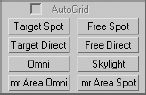
3ds Max has a total of eight light types in its Standard Light collection. The following lights are in the collection:
| Target Spotlight |
| Free Spotlight |
| Target Direct Light |
| Free Direct Light |
| Omni Light |
| Skylight |
| mr Area Omni Light |
| mr Area Spotlight |
The last two on this list have the prefix "mr" to signify that they are mental ray-specific lights. mental ray is an advanced renderer that is commonly used in production today. It offers many sophisticated and frequently complex methods of lighting that enhance the realism of a rendered scene. Because mental ray is fairly complex, it will not be covered in this book, so its lights will not be covered in this chapter.
After you read this chapter, you should be familiar enough with lighting to get started and try new things without using any advanced lighting and rendering methodologies. You will get the chance to light a radiosity effect in the next chapter.
Target Spotlight
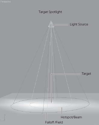
A Target spotlight, as shown in Figure 10.13, is one of the most commonly used lights because it is extremely versatile. A spotlight casts light in a focused beam, similar to a flashlight. This type of lighting allows you to light specific areas of a scene without casting any unwanted light on areas that may not need that light. You can control the size of the hotspot. This is the size of the cast beam.
The light is created with two nodes, the light itself (light source) and the Target node, at which the light points at all times. This way you are able to animate the light following the subject of the scene easily, as a spotlight would follow a singer on stage. Select the target and move it as you would any other object in 3ds Max. The Target spot will rotate to follow the target. Similarly, you can animate the light source, and it will orient itself accordingly to aim at the stationary target. (You may also animate both if you prefer.)
Click the Target Spot button, and in the Top viewport, click and drag to create a Target spotlight, as shown here.

FALLOFF/FIELD
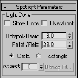
Select the light source of the Target spot. Go to the Modify panel, and open the Spotlight Parameters rollout as shown in the graphic.
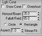
The falloff is the area in which the intensity of the beam falls off, or dissipates, creating a soft area around the Hotspot circle, as shown in Figure 10.14.
Field parameter is a function for Photometric lights, which are not covered in this introductory text.
SPOTLIGHT SHAPE
You can also change the shape of a spotlight from circular to rectangular by selecting either Circle or Rectangle in the Spotlight Parameters rollout. In addition, using the aspect value, you can set the height-to-width ratio for the hotspot for either Circle or Rectangle spots. Figure 10.15 shows a rectangular spot with an aspect of 4.0.
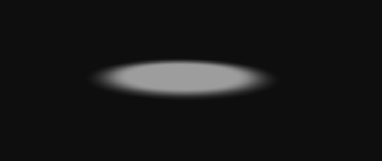
When rendered, the rectangular spot looks like the image in Figure 10.16.
SELECTING THE LIGHT
You can move (and animate) the entire light, including the light and the target, by selecting the light object in the viewport in the middle of its display, as shown in the following graphic on the left (Figure 10.17). To access the parameters of the light, you have to select the light, as shown on the right (Figure 10.17). The target does not list any parameters for the light.
INTERACTIVE CONE SETTINGS
3ds Max has the ability to control the Hotspot/Beam and the Falloff/Field parameters in the viewport. Follow these steps to interactively change a spotlight's hotspot and falloff.
Select the spotlight's source.
Click the Select and Manipulate tool in the main toolbar (

Click and drag the green circles at the end of the spotlight cone to set the hotspot and falloff ranges, as shown in Figure 10.18.


A Target Direct light has Target and Light nodes to help you control the direction and animation of the light. It also has a hotspot and beam, as well as a falloff much like the Target spot. However, where the Target spot emits light rays from a single point (the light source) outward in a cone shape, the Target Direct light casts parallel rays of light within its beam area. This helps simulate the lighting effect of the sun, because its light rays (for all practical purposes on Earth) are parallel. Figure 10.19 shows a Target Direct light in a viewport.
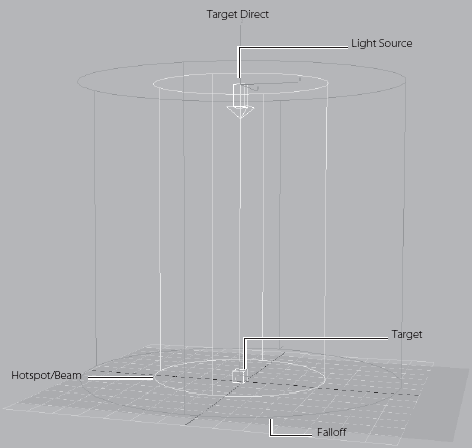
Because the directional rays are parallel, the Target Direct lights have a beam in a straight cylindrical or rectangular box shape instead of a cone.
You can create a Target Direct light much the same way as a Target spot.
Select Target Direct from the Create panel and click in an Orthographic window to set the light and define the target direction and length of the light by dragging.
Select the light for the Target direct and open the Modify panel.
In the Directional Parameters rollout, you'll find the same parameters for the Target Direct light that you had for the Target spot. The procedure to select the light is the same as for the Target spot as well. You can select the middle of the light for the whole object, or you can select either the target or light. You have to select the light to bring up the parameters for the light object.
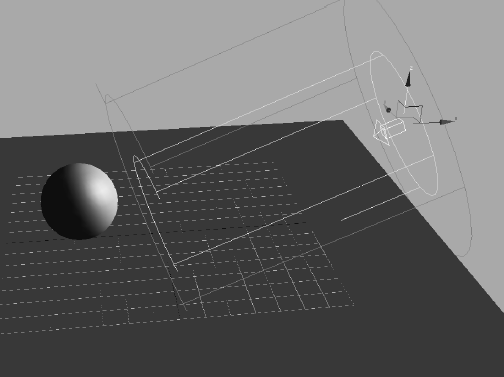
Although the spotlight and the directional light don't seem to be very different, the way they light is strikingly different, as you can see in the following graphics (Figure 10.20).
The spotlight rays cast an entirely different hotspot and shadow than the directional light, despite having the same values for those parameters.
Note
It's preferable to create lights in the Orthographic viewports because they give you a better idea of size and direction than a Perspective or Camera viewport.
A Free spotlight is virtually identical to a Target spot, except that this light has no target object. You can move and rotate the free spot however you want, relying on rotation instead of the target to aim it in any direction. A Free spotlight is shown in Figure 10.21.

You will study the General Parameters rollout later in this chapter.
Adjusting the length of a spotlight will not matter when the light is rendered; however, seeing a longer light in the viewports can help you line up the light with objects in the scene. Likewise, you can shorten the length of the light to clear some wireframe clutter from your viewports.
Spotlights (including Target spots) are great for key lighting because they are very easy to control and give a fantastic sense of direction.
The Free Direct light is identical to the Target Direct light, but it doesn't have the Target node. Its parameters are the same as the Free spot's, and it is selected and moved in the same way. Figure 10.22 shows a Free Direct light.
Directional lights (including Target directs) are also great lights to use as key lights. You can also use them for fill lights, although the hotspot size must be large to avoid seeing the edges of the hotspot.
Directional lights are also used frequently to simulate sunlight, although their beams must be quite wide to avoid any chance of seeing the hotspot or falloff area.
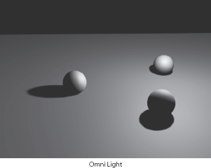
The Omni light in 3ds Max is a point light that emanates light from a single point in all directions around it. Figure 10.23 shows an Omni light.
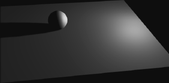
An Omni light is shown rendered in Figure 10.25. Notice how the ground plane is brighter directly below where the light sits.
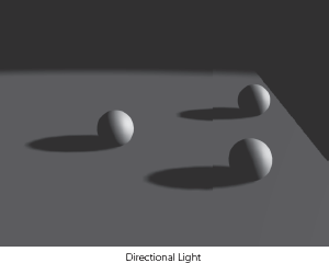
Omni lights are not as good for simulating sunlight as directional lights are. The Omni light's rays spread from a single point source, so by the time they reach their subjects, the light direction and shadows will be too disparate across the scene. In this graphic (Figure 10.26), the Omni light in the image on the left creates different shadow and lighting directions for all the objects in the scene, and the directional light in the image on the right creates a uniform direction for the light and shadow, as would the sun here on Earth.
Note
Try to avoid casting shadows with Omni lights because they will use a lot more memory than a spotlight when casting shadows.
Omni lights are good for fill lights as well as for simulating certain practical light sources that have a brighter center and fall off evenly around that bright spot in all three axes. You could even use Omni lights for all three points in your three-point lighting system, as shown in Figure 10.27 on the chessboard scene. This lighting gives the scene a nice soft feel.
Skylight
Skylight is a special 3ds Max light used with an advanced rendering method to quickly generate a scene rendered in a soft outdoor light. We will not be covering this more advanced lighting and rendering methodology; however, here is a quick introduction to the light itself.
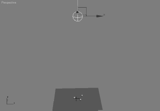
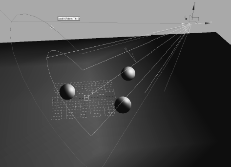
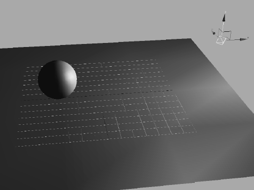
Figure 10.28 shows a skylight high above the scene with the three spheres. It is created by selecting the Skylight button in the Create panel and clicking to place it in a viewport.
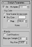
The skylight's Skylight Parameters rollout is shown in Figure 10.29.
The skylight is used to create a soft, global lighting to simulate light from the sky. This look is often seen with renders using Global Illumination or Radiosity. In these lighting/rendering solutions, the skylight creates a sky dome that sits around the objects in the scene. Light is emitted from the entire surface area of the dome to cast an even light throughout the scene, much as a sky lights an outdoor area.
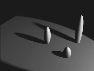
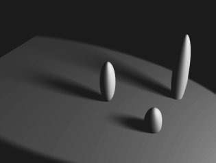
The rendering of a Skylight scene, as shown in Figure 10.30, is flat and bright. There is no definition because shadows are not enabled.
Turning on shadows gives you a beautiful render, as shown in Figure 10.31, with soft shadows and contact shadows that really make the spheres look as if they are sitting outside in afternoon light.
The render time for this frame, however, is significantly longer than any of the other renders so far in this chapter. Calculating soft light such as this is quite intensive, unless a lighting plug-in such as Light Tracer is enabled in the render setup.
Note
The Skylight light is not intended to be used without some other light source(s) in the scene. It is designed to be used only with Radiosity, Light Tracer, or mental ray rendering techniques. These techniques are more advanced, so they will not be covered in this book. It is important to learn traditional lighting and rendering methods before moving into advanced techniques.
Most of the parameters for the Standard lights are the same for all the lights and will be described in this section. You may want to create a spot or directional light so you can follow along with the information about light parameters given here.


Figure 10.31. Turning on shadows for the skylight dramatically increases render times, but it gives a nice effect with soft shadows mimicking a radiosity effect.
General Parameters Rollout
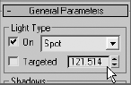
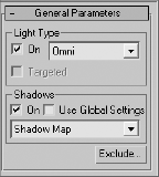
The General Parameters rollout for all the Standard lights (except for Skylight) is shown in Figure 10.32. In the Light Type section, you can change the type of light that is currently selected. Simply choose the type (Spot, Directional, Omni) from the drop-down menu.
3ds Max will replace the light with the new light type; it won't change its position or orientation. This can be immensely helpful when you are deciding which light will work best for a scene. Otherwise, you would have to delete and re-create lights to find the solution that best suited your scene.
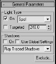
You can turn a Free spot or Free directional to a target of the same kind by checking the Targeted check box. Of course, the On check box controls whether the light is on or off in the scene.
In the Shadows section of the General Parameters rollout for these lights, you will find the controls for the shadow-casting properties of the selected light. Use the drop-down menu to select the type of shadows to cast. The two most-frequently used shadow types, Shadow map and Raytraced, are discussed later in the chapter.
The Use Global Settings toggle can be very useful. When it is turned on, all of the lights in your scene will be set to use the same Shadow parameters of the light you have selected and for which you have enabled Use Global Settings. This is useful in the event you need the same type of shadows cast from all the lights in the scene. It can save you the hassle of specifying the settings for all the lights. It does, however, limit you to the same shadow settings for all the lights. While you are learning, you should leave Use Global Settings off and set each light manually as needed. Again, shadows are covered a little later in this chapter.
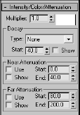
Intensity/Color/Attenuation Rollout
The Intensity/Color/Attenuation rollout, shown in Figure 10.33, is used to adjust your light's brightness and color settings.
Light Intensity
The Multiplier parameter works like a dimmer switch for a light. The higher the value is, the brighter the light will be. The Multiplier can go into negative values. A negative amount will subtract light from your scene, allowing you to create dark areas within lit areas or to remove excess light from a surface that has unwanted spill light.
Light Color
The Color Swatch next to the Multiplier is used to add color to your light. Simply click on the color swatch to open the Color Selector. The darker the color is, the darker the light will be.
Light Decay
Under the Decay section, you can set the way your light fades across distance. This is not the same as falloff with spots and directional lights, though. Falloff occurs on the sides of a hotspot, whereas decay happens along the path of the light as it travels away from the light. Figure 10.34 shows a light with no decay type set. Figure 10.35 shows the same light with its decay Type set to Inverse Decay. Figure 10.36 shows the same light with decay Type set to Inverse Square Decay. Notice the decay rate increases with each successive figure.
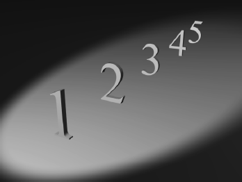


Figure 10.36. A light with Inverse Square Decay illuminates the first two numbers and begins to lose the remaining three.
If no decay is set for a light, its intensity remains at full strength from the light to infinity. An Inverse Decay diminishes the intensity of the illumination over distance traveled according to some brainy formula. An Inverse Square Decay more closely resembles the decay of real-world light, and it is a stronger rate of decay than Inverse Decay. Use this decay rate to drop off the effect of a light quickly before it reaches too far into the scene; however, you will need a stronger Multiplier value to increase your light's intensity to compensate for the much faster decay.
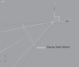
In Figure 10.37, you can quickly see and set the start of a decay in spot and directional lights by changing the Start value in the Decay section of the rollout.
In the following image (Figure 10.38) you can see a decay start that is closer to the light and its effect on the render in the top-left corner.
The start of the decay is moved closer to the spheres in Figure 10.39.

Light Attenuation
Light attenuation is another way to diminish the intensity of a light over distance. With attenuation, however, you have more implicit control on the start and end of the fade, and you can specify an area where the light fades in and then fades out. To do this, set the Attenuation distances to the desired effect.
NEAR ATTENUATION GROUP
The following values set the distances where the light fades into existence:
Start The distance at which the light starts to fade in.
End The distance at which the light reaches its full intensity.
Use Toggles on/off the use of near attenuation for the light.
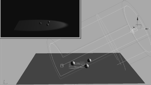
Figure 10.40 shows a render of near attenuation at work. The first numbers are darker, the back numbers are brighter.
Figure 10.41 shows a spotlight and the Attenuation display in the viewport.
FAR ATTENUATION GROUP
The following values set the distances where the illumination fades out of existence:
Start The distance at which the illumination starts to fade away.
End The distance at which the illumination has faded to nothing.
Use Toggles on/off the use of far attenuation for the illumination.
Figure 10.42 shows a render of the far attenuation on the same set of numbers, using the same light as before. Now the lights fade into darkness the farther back they are in the scene, which is similar to decay.
Figure 10.43 shows the Far Attenuation display for the spotlight.


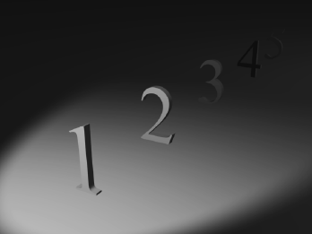
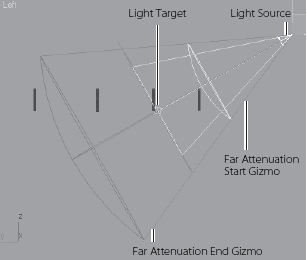
Figure 10.44 shows the Attenuation display for an Omni light in a viewport.
You can always use both near and far attenuation to set a sliver of light in your scene, as shown in Figure 10.45. As you can see, attenuation is a more precise way to set a diminishing light intensity over the Decay Type.


Note
Both decay and attenuation are important to use when the light needs to be realistic. Light decays in real life; your renders will assume a higher fidelity when the lights in them decay. The effect may be subtle, but it can make a large difference.
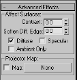
Advanced Effects Rollout
Contrast and Soften
By adjusting the Contrast and Soften Diffuse Edges values, you can alter the way the light hits your surface. The following image (Figure 10.46) was rendered with default Contrast and Soften Diffuse Edges values,
This image (Figure 10.47) was rendered with a Contrast of 25 and a Soften Diffuse Edges value of 50. It has deeper contrast, but with slightly softer values leading from the diffuse color.
Contrast Changes the contrast level between the diffuse and ambient areas of the surface when lit.
Soften Diffuse Edge Controls the softness of the edge between the diffuse and ambient areas of the lit surface.
Light Components
Light in a CG program is differentiated into an ambient, a diffuse, and a specular component. The ambient component of light is the general ambient light in a scene. There is no direction to ambient light, and the light itself is cast evenly across the extent of the scene. The diffuse component of light is the way it illuminates an object by spreading across its surface. The specular component of light is how the light creates highlights on a surface, especially when that surface is glossy. (You may want to review the discussion of these components in Chapter 7, "Materials and Mapping.")
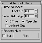
In the Affect Surfaces section of the Advanced Effects rollout, you can toggle the check boxes that will render only those components of the light on the surfaces they illuminate. This is a good way to separate your renders into lighting components that you can later control in compositing, although it leads to a longer workflow.
Figure 10.48 is rendered with the diffuse component of the lights in the scene.


Ambient light in 3ds Max is not a light per se; it is a global setting in the render environment. Ambient light, in short, is an even light with no direction or source. It is a way to globally brighten the entire scene to add an even light to all objects. Using too much ambient light will wash out your objects and give you flat renders.
To set an ambient light level in your scene, in the main menu select Rendering → Environment to open the Environment and Effects window shown in Figure 10.51.

To set an ambient light, click on the Ambient color swatch under the Global Lighting section and pick an appropriate color. The brighter the color value, the brighter the ambient light will be throughout the scene.
Note
You can also create an ambient light in your scene by creating an Omni light and toggling on the Ambient Only check box under the light's Advanced Effects Parameters rollout.
Now that we have an overview of how lights work in 3ds Max, let's put them to good use and light the Red Rocket textured model from Chapter 7. Because lighting goes hand in hand with rendering, we will create the basic lighting setup based on the three-point system discussed earlier in this chapter. We'll work more with the lighting and settings when we get to Chapter 11, "3ds Max Rendering."
Note
Occasionally, setting a project and opening a scene file fails to open all the appropriate image files used in the scene. In these cases, you will have to reconnect the image files needed by navigating to their folders (usually in the project's SceneAssets/Images folder) and picking the files manually. 3ds Max will give you the error message and give you a chance to replace the file when you first open the scene.
This scene is very simple (Figure 10.52). It is the final rocket from Chapter 7. (If you prefer, you can use your own rocket file.).
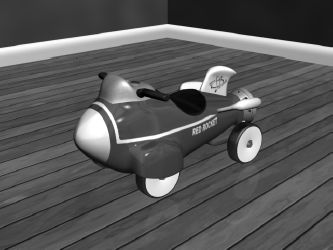
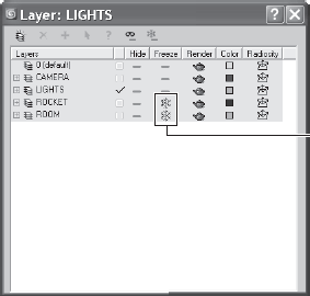
The rocket, with all its many parts, has been frozen in the scene on the CD so you can work freely without worrying about selecting objects other than the lights. The rocket and the room it is in can be unfrozen by going to the Layer Manager and clicking the Unfreeze icon next to the Rocket layer (as shown in Figure 10.53).
To begin lighting the rocket, follow along here:
Go to the Create panel and select the Lights icon (

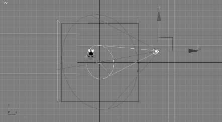
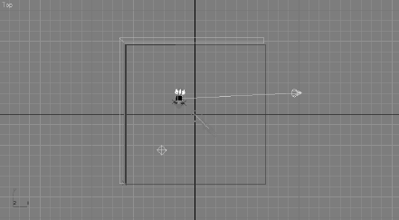
Click to create a Target spot. Go to the Top viewport, and click and drag from the right side of the viewport toward the middle, as shown in Figure 10.55. The first click will create the camera; the drag places the target.
Note
When you create your first light, the scene will turn black momentarily. This is because when you create a light, the default lights are removed from the scene.
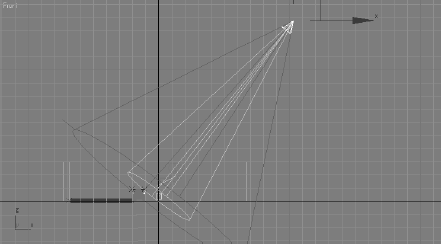
Move to the Front viewport, select the light, and move it up as shown in Figure 10.56. If your front view is not visible, simply select one of the viewports and press F for the Front viewport.
Name the light Key Light. This light will have shadows and give the scene its main source of light and direction.
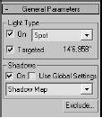
Go to the Modify panel, check the On box under Shadows, and set the Shadow Type to Shadow Map, as shown in Figure 10.57. This is the default shadow type. Later in the chapter, we will expand on all the shadow types and their uses in 3ds Max.
Go to the Intensity/Color/Attenuation rollout in the Modify panel, and set the Multiplier to 0.8. As you learned earlier in the chapter, the Multiplier acts like a dimmer switch and controls the light's brightness.
In the Spotlight Parameters rollout, change the Hotspot/Beam parameter to 18 and the Falloff/Field value to 38, as shown in Figure 10.58. Both these parameters affect the width of the cone of light. The closer the two values are, the sharper the edge of the light will be; the farther they are from each other, the softer the light will be.

Try a render (press F9 for a Quick Render) and you will see the rocket as shown in Figure 10.59.
Not bad, but look at how dark the shadow is. Once we add a fill light, the shadows will be better. For the fill we'll use an Omni light. You may also notice that the rocket looks a bit like it is floating above the ground. Let's address that issue first, in the following steps:
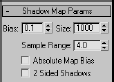
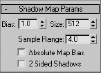
Select the key light (the Target spot), and in the Shadow Map Params rollout (Figure 10.60), change the Bias to 0.1. Bias moves the shadow toward or away from the object. The shadow is too far away from the rocket, and that is why in Figure 10.59 it appears to be floating.
In that same rollout, change the Size parameter to 1500. Size specifies the amount of resolution in the shadow; the more the pixels the more crisp the edge of the shadow will appear.
Go back to the Create panel to create another light. Click to create an Omni light. In the Top viewport, click in the bottom-left corner to place the Omni as shown in Figure 10.61.
In the Front viewport, move the light up about half the height of the backdrop.
The Omni is just a fill light in this scene, so we don't want any shadows from it. Furthermore, we will turn off specular highlights on the rocket from this light to make sure the render looks as if there is only one light in the room. By default, shadows are always off, but not the specular, so we will turn it off manually. With the Omni light selected, go to the Modify panel and under the Advanced Effects rollout, uncheck Specular as shown in Figure 10.62.
Go to the Intensity/Color/Attenuation rollout for the Omni light, and change the Multiplier to 0.3.
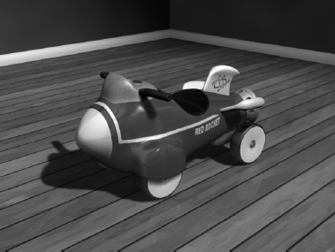
Render again (press F9) and you'll see the render looks better, but that the rocket's shadow is still dark (Figure 10.63).
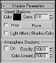
To fix the darkness of the shadow in Figure 10.63, we could add more lights to the scene, but then the scene would get too bright. The solution is to adjust the density of the shadow (you will see more on shadows in the next section in the chapter). Select the key light, go to the Modify panel and in the Shadow Parameters rollout, change the Object Shadow's Dens parameter to 0.8 (Figure 10.64).
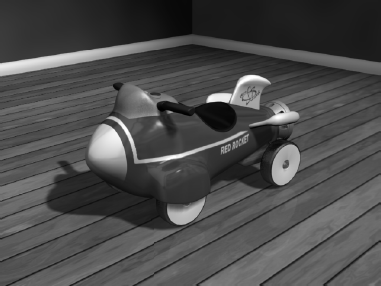
Press F9 for another Quick Render (or press the Teapot icon in the main toolbar), and you will see that the rocket's shadow looks much better (Figure 10.65).

This exercise used what is arguably the most popular shadow-casting method. There are other ways to cast different types of shadows, each with its own advantages and distinct look. In the following section, we will explore different shadowing techniques.
When creating shadows don't be too quick to smother your scene with light or too eager to show off your careful modeling work and textures. Leaving objects in shadow and darkness is as important as revealing them in light. You can say a lot visually by not showing parts of a whole and leaving some interpretation to the audience.
Using shadows intelligently is very important in lighting your scenes. Without the shadows in the rocket scene, the rendered image would look weird. The rocket would float in the scene and have no contact with its environment. You would also lose a great deal of the sense of direction without shadows.
A careful balance of light and dark is important for a composition. The realism of a scene is greatly increased with the simple addition of well-placed shadows. Don't be afraid of the dark. Use it liberally, but in balance.
You can create the following types of shadows in 3ds Max:
| Advanced Raytraced |
| mental ray Shadow Map |
| Area Shadow |
| Shadow Map |
| Raytraced Shadows |
Each type of shadow has its benefits and its drawbacks. The two most common types used are Shadow maps (which you've already seen) and Raytraced shadows.
When you use shadows, controls in the Shadow Parameters rollout and the shadow type-specific rollouts are available when you select the shadow type.
Shadow Parameters Rollout
You should always check your light's Multiplier values first to make sure your fill light does not wash out your shadows before you adjust the shadow parameters themselves. For instance, the fill light(s) generally has a lower intensity than the key light(s).
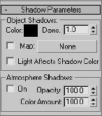
Click on the Color Swatch to pick a color for your shadows. More often than not, you will have your shadow colors at black, if not close to black. You can also control the density of the shadows by adjusting the Density value. As you can see in Figure 10.66, adjusting the density changes how much of the shadow is rendered. A Density of 0 will turn off your shadows in essence.

Interestingly enough, you can also apply a map to your shadow by checking the Map box and clicking on the button bar currently labeled None. From there, you can choose a map. In Figure 10.67, a checker map was mapped to the shadow on a fruit arrangement. Notice how the checker pattern shows up just in the shadows between and on the fruit.

Selecting a Shadow Type
For the most part, you will be more than happy with the results from a Shadow Map shadow in your scenes. However, to get shadows to respond to transparencies, you will need to use Raytraced shadows. Additionally, if you need to soften your shadows the farther they are cast from the object, you will need to use Area Shadows. These shadow types are discussed next.
Shadow Maps
The Shadow map generates a bitmap file during a pre-rendering pass of the scene. This map is used to place the shadows in the final render. It is often the fastest way to cast a shadow. However, Shadow Map shadows do not show the color cast through transparent or translucent objects. Once you select Shadow Maps in the General Parameters rollout for a light, the Shadow Map Params rollout appears. It is shown here.
The following parameters are useful for creating Shadow maps:
Bias The shadow is moved, according to the value set, closer or farther away from the object casting the shadow. Figure 10.68 shows how the bias moves the shadow away the higher the value is set.

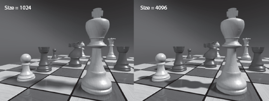
Size Detailed shadows will need detailed Shadow maps. Increase the Size value, and 3ds Max will increase the number of subdivisions for the map, which in turn increases the detail of the shadow cast. Figure 10.69 compares a low Shadow Map Size to render the chessboard with one four times larger. Notice how the shadows on the left (Size = 1024) are somewhat mushy and less noticeable and the shadows on the right (Size = 4096) are crisp and clean. You don't want to set your Shadow Map size to be too high, though. It will increase render time for little to no effect. A range around 2048 is usually good for most cases. Larger scenes like this chess board that have a large scale to them will require higher Size values such as the 4096 used. The rule of thumb is to use the lowest Size value that will get you the best result for your scene.
Note
In some scenes, you may discover that no Shadow Map size will give you good results (for instance in large outdoor scenes). In these cases, you will have to revert to a different shadow method, such as Raytraced shadows.
Sample Range This creates and controls the softness of the edge of shadow-mapped shadows. The higher the value is, the softer the edges of the shadow will be. Figure 10.70 shows you how a soft edge (on the left) can make the lighting seem weaker or farther away from the subject than crisp shadows (on the right).

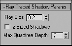
Raytraced Shadows
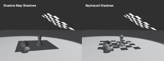
Raytracing involves tracing a ray of light from every light source in all directions and tracing the reflection to the camera lens. You can create more accurate shadows with raytracing. However, the render takes significantly longer to calculate. Raytraced shadows are always hard edged, yet they are realistic for transparent and translucent objects. Figure 10.50 shows a pair of chess pieces rendered with a plane casting a shadow over them. The plane has a checker mapped to its opacity, so it has alternating transparent and opaque squares defining the checkerboard. On the left side of the image in Figure 10.71, the light is casting Shadow Map shadows, while on the right the light is casting Raytraced shadows.
Use Raytraced shadows when you need highly accurate shadows or when Shadow Map resolutions are just not high enough to get you the crisp edges you need. You can also use Raytraced shadows to cast shadows from wireframe rendered objects.
Creating Soft Shadows Due to Distance
The only way you will be able to create a natural shadow that softens the farther it gets from the casting object is to use Area shadows. These types of shadows are natural. If you notice a telephone pole's shadow, the farther the shadow is from the pole, the softer the shadow becomes. Adding such a shadow to a render can greatly increase the realism of the scene.
To enable a soft shadow such as this, select Area Shadows as your shadow type. By default, the Area Shadow will work for you. Figure 10.72 shows a regular Raytraced shadow.
Figure 10.73 shows an Area shadow at the default settings.

Go to the Area Shadows rollout shown in Figure 10.74. To adjust the softness of the shadows, you will not want to increase the Sample Spread because that parameter, just like the Sample Range of the Shadow Map shadow, softens the entire shadow. A true shadow is crisp where it meets the casting object and softens as it casts away.

To further soften the ends of the shadows, in the Area Light rollout, set the Length to 80 and the Width to 60. This will increase the softness of the shadow in a realistic way, while keeping the contact shadow crisp. However, the render, shown in Figure 10.75, does not look very good. The soft ends are very grainy.
You will need to increase the quality of the shadow, so set the Shadow Integrity to 6 and the Shadow Quality to 10. The render will take longer, but you will get a beautiful shadow, as shown in Figure 10.76.

Using this rollout, you can assign and manage atmosphere effects and other rendering effects that are associated with lights. In the following exercise, you will learn how to create a volumetric light (similar to a flashlight shining through fog). You will also learn how to exclude objects from a light, so that the light does not illuminate them. This is an important trick to know.
Creating a Volumetric Light
Let's create a fog light now.

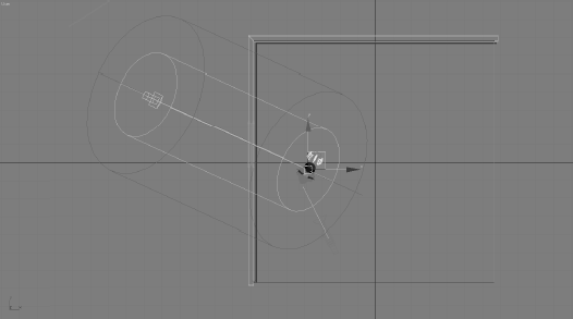
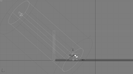
Move your pointer to the Top viewport, and click and drag from the top of the viewport down toward the rocket.
As shown in Figure 10.77, the light begins outside the room the rocket is in. This scene is already equipped with two Omni lights to act as fill lights in the room.
Move to the Front viewport and move the light up along the Y-axis, and then move the target so it is centered to point the light directly on the rocket, as shown in Figure 10.78. Make sure the light is shining into the room from outside through the window.
If you do a Quick Render (F9), you will see that the scene is being lit from the direction of the light (Figure 10.79).

This first render probably looks very odd. The rocket and floor have reflections on them; so they show up even if there is no light in the scene at all. That is the way reflections work.
Adding Shadows
Now you need some shadows in the scene.
In the General Parameters rollout for the light, go to the Shadows section and check the box to enable shadows. Select Shadow Map from the drop-down menu. This will turn on Shadow Maps shadows for this light.
Go to the Shadow Map Params rollout and set the size to 2048; this will add some sharpness to the shadow's edge and make it more like a daylight shadow. Also change the Bias to 0.1, which will move the shadow so it is under the rocket. If you do a Quick Render, you won't see any shadows (as shown in Figure 10.80).

This is because the window is blocking the light. The window glass object has a Material that has the Opacity turned down to 0. However, Shadow Map shadows don't recognize transparency in materials. To solve this problem, you need to exclude the Window Glass object from the Light.
Excluding Object from a Light
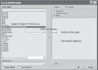
The Exclude button is in the General Parameters rollout for the light, just below the Shadows. Click the Exclude button to bring up the Exclude/Include window shown in Figure 10.81.
Click on the Glass object and press the right arrows in the middle of the window (Figure 10.81) to add the Glass to the other side, excluding the object from receiving light and casting light. Click OK.
Quick Render your scene to take a look. Now you can see shadows. We didn't exclude the whole window with its frame because the inside frame is a nice detail to cast shadows. Figure 10.82 shows the render with the shadows.

Adding a Volumetric Effect
The whole point of this exercise is to add volume to the light. This will give this scene some much needed atmosphere.
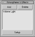
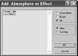
Go to the Atmosphere and Effects rollout for the light. Select Add from the rollout to open the Add Atmosphere or Effect window, which is shown in Figure 10.83.
In the window, select Volume Light and click OK to add the effect to the light.
Volume Light will be added to the rollout, as shown in Figure 10.84.
Render the scene. You should see a render similar to Figure 10.85.
To adjust the volume light, select the Volume Light entry in the rollout and click the Setup button. This will bring up the Environment and Effects dialog window. Scroll down to the Volume Light Parameters section to access the settings for the volume light, shown in Figure 10.86. Experiment with different settings to see how the volume light renders.

Volume Light Parameters
The default parameters for a volume light will give you some nice volume in the light for most scenes, right off the bat. If you want to adjust the volume settings, you can edit the following parameters:
Exponential The density of the volume light will increase exponentially with distance. By default (Exponential is off), density will increase linearly with distance. You will want to enable Exponential only when you need to render transparent objects in volume fog.
Density This value sets the fog's density. The denser the fog is, the more light will reflect off the fog inside the volume. The most realistic fogs can be rendered with about 2 to 6 percent Density value.
Most of the parameters are for troubleshooting volume problems in your scene if it is not rendering very well. Sometimes you just don't know what that problem is and you have to experiment with switches and buttons. The Noise settings are another cool feature to add some randomness to your volume:
Noise On This toggles the noise on and off. Render times will increase slightly with Noise enabled for the volume.

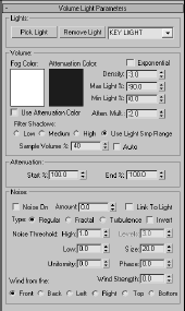
Amount This is the amount of noise that is applied to the fog. A value of 0 creates no noise. If the Amount is set to 1, the fog renders with pure noise.
Size, Uniformity, Phase These settings determine the look of the noise and let you set a Noise Type (Regular, Fractal, or Turbulence).
Adding atmosphere to a scene can heighten the sense of realism and mood. Creating a little bit of a volume for some lights can go a long way to improving the look of your renders. However, adding volume to lights can also slow your renders; so use it with care. Also be aware that adding too much volume to a scene may look peculiar; so use volumetric light sparingly and with good reason. Reserve it for when it is called for in the scene and will add ambience to the image.
If several lights are in your scene and you need to adjust all of them, selecting each light and making one adjustment at a time can become tedious. This is where 3ds Max's Light Lister comes in handy. Accessed through the main menu bar by choosing Tools → Light Lister, this floating palette gives you control over all of your scene lights, as shown in Figure 10.87.
This is the perfect tool to edit your lights once you have them set up initially. You can choose to view/edit all the lights in your scene or just the ones that are selected. Using this easy dialog window gives you instant access to almost all the important light parameters in one place. When you adjust the values for any parameter in the Light Lister window, the changes are reflected in the appropriate place in the Modify panel for that changed light.

Lighting is the aspect of CG that is arguably the most difficult to master (some users think it's even harder than character animation), and it is the most easily criticized. People in the CG industry can tell very quickly when lighting is done poorly.
In this chapter, you began by reviewing some key concepts in CG lighting, including three-point lighting. Then you learned the different types of lights that 3ds Max has to offer, from default lights to Target spots, and how to use them. You dove into the common light parameters to gauge how best to control the lights in your scene before you moved on to creating all different types of shadows. You ran through a set of short exercises in which you created a volumetric light for a fog effect and finished with a tour of the Light Lister window.
Several books are devoted to CG lighting. It is a craft that takes getting used to. This chapter introduced you to the concepts and tools you need to begin. Now it's your turn to take the models you have created (and the ones you will create in the future), texture them, and light scenes with them to develop an eye for the ins and outs of lighting.
There really is no quick way to learn how to light. It would be quite a disservice to pretend that a chapter, or even an entire book, will give you everything you need to know. Take the information and references in this chapter and apply them on your own. Working on your own may not sound like fun, and it may not seem as easy as being guided step by step, but it is the best education you will get.