Anticorrosion Coatings with Self-Recovering Ability Based on Damage-Triggered Micro- and Nanocontainers
D. Grigoriev Max-Plank Institute of Colloids and Interfaces, Am Muehlenberg 1, Potsdam-Golm, Germany
Abstract
Anticorrosion coatings demonstrating the ability to recover their protective function after being damaged by different destructive factors represent one particular class of the new generation engineering materials—so-called self-materials, which are one of most rapidly growing fields in modern material science.
A well-established concept to impart the self-recovering or self-protecting features to an organic coating is nowadays the use of micro- or nanocontainer structure when protective agents (corrosion inhibitors) entrapped in containers are embedded in the coating matrix. Thus, nano- or microcontainers with active loads are the crucial element of novel anticorrosion coatings.
In the chapter at hand, several different ways to produce containers for further incorporation into coatings as well as some types of containers for self-recovering anticorrosion coatings are described.
Incorporation of containers in the coating matrix, with subsequent experimental modeling of scratch propagation causing containers to rupture and release active agents at the damaged site, demonstrated promising effects, confirming the ability of novel coatings to recover their anticorrosion features. For the sake of visualization, the results of the corrosion testing according to the ISO 9227 procedure for new anticorrosion coatings are compared with those for conventional coatings.
8.1 Introduction
8.1.1 Corrosion as a global economic problem
The tremendous annual detriment directly resulting from corrosion of metallic materials and structures and the corresponding huge economic impact is a very important issue worldwide. According to a study conducted in 1999-2001 by CC Technologies Laboratories, Inc., supported by the U.S. Federal Highway Administration (FHWA) and the National Association of Corrosion Engineers (NACE), the total annual estimated direct cost of corrosion only in the United States is an overwhelming $276 billion.1 Similar results were reported for Europe, where every year more than €200 billion need to be invested just to recover losses related to corrosion degradation. Thus, even in the most economically advanced countries the material losses and performance failure costs connected with corrosion are estimated to be 3-4% of GDP.2,3 The corresponding information for the less economically developed countries is only partially accessible but seems to be more dramatic.2 Therefore, preventing corrosion and improving corrosion protection are nowadays the most important tasks challenging the community of corrosion scientists, engineers, and technologists.
8.1.2 Methods for combating corrosion: short overview
Because the corrosion process begins usually on sites where a metallic construction adjoins an aggressive surrounding, the typical place of the corrosion occurrence is the surface of the metal of which this construction is made, or, speaking more strictly, the interface between the metal and a medium. Thus, to date, all known approaches for preventing and controlling corrosion are directly or indirectly related to the stopping or slowing of the interfacial/surface reactions of the corresponding metal (alloy) with the aggressive environment. This can be achieved in many different ways. These ways may be generalized into two categories: one is a big group of approaches using chemical or physicochemical modification of the entire bulk material; and the second is an even more numerous group of approaches related to the surface/interfacial modification of the material to be protected.
Typical examples of approaches from the first group are the use of various corrosion-resistant alloys,4,5 polymers,6–8 and composite materials,9 or catodic protection.10
On the other hand, such approaches as use of different organic,11 ceramic,12 and metallic protective coatings,13 anodic protection,14 application of diverse corrosion inhibitors15–18 can be mentioned as conventional instances of the second group.
Among the wide variety of interfacial protective approaches only briefly named above, the use of organic coatings is probably the most common and economically sound approach to improve corrosion protection and, therefore, durability and performance of metal products and constructions in an extremely broad area of applications ranging from aviation to household appliances.
Depending on the metallic substrate to be protected and on the particular requirements of a coating’s anticorrosion efficiency and its other properties, a modern organic protective coating may be a quite complex construction. Excluding all cases of specific applications with special demands on the anticorrosive performance, a conventional contemporary anticorrosion coating can be regarded as a layered structure most commonly composed of three layers beginning from the substrate: a thin pretreatment layer, a primer, and a topcoat.
In some cases, the anticorrosion performance of these layered build-ups can be provided merely by the good isolation of the metal substrate from the corrosive environment, that is, the corrosion protection of these coatings has only a passive character because none of the layers included in the coating contain any additives that can prevent the onset of corrosion or slow down its propagation. Therefore, any damage to the mechanical integrity of the coating matrix in the case of such a passive coating is connected with the total failure of its protection performance at least in vicinity of the damaged site and, as a consequence, leads to the unrestricted development of corrosion.
Therefore, the addition of different anticorrosive agents, predominantly inorganic anticorrosion pigments,19,20 to a passive matrix became more and more common to impart at least some active anticorrosion function to a passive coating.
Especially successful was the application of hexavalent chromium compounds (Cr VI). These substances were widely used to create pretreatment conversion films.21,22 Because of the strong oxidation effect of chromates, the metal substrate to be protected plays the role of reductant, and on its surface the tight solid film of hydrated chromium (III) oxide is formed.23,24 The relatively thin conversion film obtained in this manner possesses very good barrier properties and can moreover confer on the coating the ability to heal itself upon damage. This ability is provided by the excess of chromate ions that become embedded into the conversion layer during its formation but remain only physically bonded with this layer. As a result, they can be easily released upon destroying the mechanical integrity of the coating exactly at the injured site and react again with the metal substrate, providing both cathodic and anodic passivation of the surface.25,26
Additionally, the gradual release of chromates incorporated in the matrix of the conversion film and their subsequent transfer to surface defects via the contiguous aqueous phase impart the long-term protection to it.27–29
Chromate conversion films are usually prepared by chemical treatment and have a low thickness. Thus, the amount of excess chromates that can be accumulated inside these films is not sufficient30 for the sustained corrosion protection of the substrates. To increase the sustainability of the protective effect, chromate anticorrosive pigments such as CaCrO4, SrCrO4, or BaCrO4 should be incorporated into the more extended primer layer.31–35
However, the oxidative power of chromates causes several very serious negative effects: importantly, high environmental toxicity coupled with this health concern show correlations between chromate pollutions and different cruel deceases such as cancer or gene damage.36 These health and environmental incompatibilities as well as the safety problems related to them were the driving forces to ban the use of chromates in corrosion protection solutions and to eliminate them from various applications.37
To date, the use of chromates has been stopped in almost all main industries and steadily increasing efforts are being made to find environmentally benign substitutes. Different alternative solutions have been suggested. A number of compounds of several transition metals in a high oxidation state have been used for chemical conversion coatings, such as titanium,38 vanadium,39 zirconium and niobium,40 manganese,41,42 cobalt,43 molybdenum,44 tungsten and silicon,45 cerium,40,46–49 and other rare earth metals.50,51 Other endeavors embrace such techniques as electrochemical chromate-free oxidation treatment (anodizing),52–54 diverse organic-inorganic pretreatments,55,56 and the application of organic inhibitors directly onto the metal substrate surface.57 Another attempt to find appropriate alternatives to chromates was reported by Dufek and Buttry.58
One of the most conventional methods to replace toxic chromates in organic anticorrosion coatings is the use of various inorganic pigments on the basis of zinc compounds (especially, zinc phosphate) for addition to the primer layer.20 These essentially less harmful additives have, however, an essentially lower protective efficiency. To attain an appropriate level of anticorrosion performance, much higher amounts of zinc phosphate should be included in a coating formulation. As a consequence, the growing ecological impact of their use on the environment, especially in the long-term, has to be taken into account. These concerns have already initiated the development of coating solutions free of zinc phosphate use,59 with the goal of its gradual elimination in the future.
Unfortunately, an equivalent substitution for chromates has until now not been found. Moreover, most of the studies of chromate-free protective solutions have unambiguously led to the conclusion that chromates provide outstandingly better anticorrosion performance compared with any other coatings developed so far. Therefore, the application of Cr (VI) compounds has been temporarily allowed as an exception in some industries, such as the aerospace industry, where the very high requirements for anticorrosion performance are mandatory because of enhanced safety standards.60 Simultaneously, the community of anticorrosion specialists continues more and more intensive tries to propose and to develop novel additives, techniques, and approaches for corrosion protection in order to attain solutions with equivalent to or even better performance than that of chromium (VI) compounds.
The direct incorporation of corrosion inhibitors in one of the layers (pretreatment, primer, or even topcoat) in the protective organic coating is a most obvious way to impart to this coating the ability to react actively to the corrosion-inducing factors.61–63
However, a lot of different obstacles can occur at this straight-line solution because of the specific physicochemical properties of the inhibitors applied and their interactions with other components of the coating system. These interactions can lead to a significant impairment or even to the failure of the protective performance of the coating.
Optimal effectiveness of an inhibitor can only be attained if its concentration in the closest proximity to the damaged site is in a certain “proper” range. Thus, too low inhibitor solubility will lead to its lack in the damage environment and consequently to the weak feedback activity. Whereas the solubility is too high, the substrate can only be protected for a relatively short time, after which the inhibitor depletion state will be rapidly attained. High osmotic pressure is another drawback related to the too high inhibitor solubility, which usually results in strong blistering and even delamination of the coating matrix from the substrate under protection. The osmotic pressure can also accelerate the water penetration across the coating, thus acting as a semipermeable membrane and causing the destruction of the passive coating matrix.64 Moreover, the adverse chemical interactions between inhibitor and other components of the coating matrix lead to significant shortcomings in its stability and to the worsening of the barrier properties of the coating system as a whole.65 The structural, chemical, and acidic/alkaline properties of the passive matrix determine the intensity of its interaction with the inhibitor and therefore the release rate of the latter. Furthermore, the freely dispersed state of an inhibitor leads quite often to its spontaneous leakage, causing a surface depletion of the inhibitor during aging.66
8.2 Micro- and Nanocontainers-Based Approach to the Protective Organic Coatings: Self-Healing Versus Self-Protecting
The idea to incorporate the previously encapsulated active agents in various materials or coatings to make them self-healing or self-restoring has been initially inspired by numerous examples from the living nature. First of all, the skin of humans and various mammalians as well as some other tissues demonstrate unique features to recuperate its integrity after being injured by external impacts (self-restoring) and to disable several types of aggressive species, mainly of environmental origin, adhering to its surface (self-protecting). It is also notable that the named abilities are always activated by external destructive factors, playing the role of on-demand triggers, such as integrity damage, or chemical or microbial attack, working in a very sustainable manner.
Efforts to mimic these natural features in diverse artificial engineering materials in order to impart to them the ability to reestablish their functionalities autarkically was started approximately three decades ago. Proposed in the early 1990s67,68 and elaborated initially for the self-repair of materials integrity in the bulk,69 this concept was then transferred to interfaces, mainly to organic anticorrosion coatings for metal substrates.64,70–72
The active feedback behavior of micro- or nanostructured material is essentially determined by its specific design. To date, the following approaches can be distinguished to fashion the fine structure of self-repairing materials: (1) based on incorporated micro- or nanocontainers, (2) based on embedded network of microcapillaries (“vascular”), and (3) intrinsic.73
Because of universality and high variability in realization, approach connected with the use of micro- or nanocontainers (further—“containers”) embedded in the material matrix is the most established now. Incorporation of containers loaded with diverse active agents enables the active feedback of the system upon the action of factors leading to the material damage because these work simultaneously as opening triggers for the containers and therefore for the release of active agents.
Most frequently, so-called sealants are used for the encapsulation in containers providing to the bulk phase of material the reestablishment of its mechanical integrity and the corresponding mechanical properties. Hence, the amount of sealing agent encapsulated in the containers applied for this purpose has to be sufficient for filling up the cracks in the interior of material bulk. This requires the use of quite large, typically micrometer-scale containers with the considerable volume fraction in the bulk.
Upon transfer of the same concept to the almost two-dimensional case of protective coatings, it is necessary to take into account several intrinsic constraints limiting the highest possible volume of the encapsulated sealant. First, this volume is closely related to the size of containers. Second, the containers volume fraction within the coating matrix also restricts the sealant volume that could be potentially released at the fracture site. These two parameters of the containers plurality are of key importance for their applicability in a certain coating. Only containers with size of several times smaller than the thickness of the coating can be embedded without damaging their integrity. Moreover, too high volume fraction can cause the formation of polydisperse container aggregates with the upper size cut-off exceeding the coating thickness.
The quantitative estimation of the protective capacity of the coating with the sealant-filled containers can be done as follows. Let us take into consideration a protective coating with thickness H and depth D which is damaged by a rectangular scratch with the width L and the depth attaining the surface of the metal substrate (Figure 8.1).

The monodisperse spherical core-shell containers with the size 2R and core radius r filled with sealing agent are homogeneously distributed in the coating matrix with the volume fraction φ. Only containers located at position x ≤ r related to each scratch face will be damaged at the scratch propagation. Thus, all these containers are distributed in the part of the coating matrix adjacent to the scratch which volume can be given by a simple expression:
Volume of all containers distributed within this matrix volume is then:
Obviously, number of containers Nc in the same volume is given by the ratio of their total volume to the volume of a single container:

Multiplying the amount of the sealant encapsulated in the single container and by their number (Equation (8.3)) the total amount of sealant encapsulated within the damaged volume is obtained as:
Part of the scratch which can be filled up by the total encapsulated sealant is given by the ratio of volume expressed by Equation (8.4) to the total scratch volume:

If the thickness of the container shell is negligible small comparing to its diameter, that is, if R ~ r, the Relation (8.5) can be simplified to the form:

The physical meaning of this relation is straightforward: For any reasonable volume fraction (for instance, for φ = 0.1) of containers with the size 10 μm and very thin shells, damage caused by the scratch can only be completely sealed when the latter has a width < 1 μm, that is, only submicrometric scratches can be recovered.
Considerably larger defects whose onset is also quite probable during the service life of a typical protective coating cannot be sealed even partially when a protective coating based on the containers filled with the sealing agent will be implemented in practice. The demonstrated limitations in the performance of self-repairing anticorrosion coatings based on the containers filled with sealants determine the predominant loading of the containers rather with protective agents (e.g., corrosion inhibitors) than with sealing ones.
The situation with the maximal amount of the sealing agent released from containers upon damage can be significantly improved, if the elongated containers, that is, containers with the aspect ratio other than unity are incorporated into coating matrix.74 The strongly elongated containers with the aspect ratio of 10 can release an almost twofold higher amount of sealing agent. Moreover, the orientation of these containers to the crack plane can also influence the sealing efficiency of the containers-based coating: if all containers are situated perpendicular to the plane of crack, up to four times higher improvement is expected. On the other hand, parallel orientation of containers and the crack leads to the decrease of the sealing capacity up to 50%. However, even the use of elongated containers filled with the sealant cannot ensure the complete self-restoring of the scratches with widths essentially exceeding the range of several micrometers.
On the contrary, efficiency of the encapsulated inhibitor for the protection of the bare metal substrate freshly created by the scratch is considerably higher: Let us imagine spherical containers with R = 1 μm and φ = 0.05 filled with an inhibitor possessing a molecular weight Mw of 500 g/mole and a density ρ of 1 g/cm3.
Following the similar consideration as previously, the maximal value of inhibitor that may be adsorbed on the scratch surface can be calculated as
where L and H are width of the scratch and the thickness of the coating, respectively.
Assuming a quite realistic coating with the thickness H = 70 μm, one obtains Γmax = 0.014/L μmole/m2. In other terms, Γmax values of some tens of micromoles per square meter are derived for typical millimeter-range scratches. These values are at least one order of magnitude higher than common saturation adsorption values Γ∞ reported for some organic inhibitors.75,76 As a result, defects of the coating surface with even larger centimeter-wide areas can be fully protected by the inhibitor amounts released from abovementioned containers.
Therefore, the term “self-protecting”77 in relation to coatings is more appropriate to use than “self-healing” since their physical integrity is usually not reestablished due to the protective effect of inhibitor released from containers, whereas the “main” anticorrosion functionality of such a coating can be completely recovered.
The key element of novel self-protecting anticorrosion organic coatings is a plurality of micro- or nanocontainers embedded in the coating matrix and possessing the triggered on-demand ability to release protective agents. In the following paragraphs of this work, the attention will be concentrated on the different types of containers applied in novel coatings, approaches and techniques used for their preparation, their morphology and release properties, distribution in coatings after curing, as well as the anticorrosion performance of container-based organic coatings.
8.3 Types of Containers and Methods of Their Preparation
Several types of nano- or microcontainers can be used for incorporation in the matrix of new self-protecting coatings: containers based on layered double hydroxides (LDHs); containers with porous or hollow ceramic core primarily soaked with inhibitor and then encased by polyelectrolyte (PE) shell with stimuli-responsive ability; containers with porous or hollow ceramic core impregnated by inhibitor and sealed then with the stimuli-responsive stoppers at the pores ends; and polymeric and composite containers possessing inhibitor-rich core and stimuli-responsive shell prepared on the basis of direct or inverse emulsions. All these types of containers have their specific peculiarities related to their preparation, loading with active agents (inhibitors), and incorporation in the coating matrix, which are discussed in more detailed in the next sections.
8.3.1 Nano- or microcontainers on the basis of LDHs
LDHs, also called as hydrotalcite-like substances,78 are naturally occurring clay-based nanostructured microparticles. Their composition can be expressed by the following general formula (M1 − x2 +Mx3 +(OH)2)Ax/nn − ⋅ mH2O where the cations M2 + can be represented by Mg2 +, Zn2 +, Fe2 +, Co2 +, Cu2 +, and so on, and M3 + can be represented by Al3 +, Cr3 +, Fe3 +, Ga3 + and others. Possessing a brucite-like structure with octahedral holes where some divalent cations were exchanged with various trivalent ones, LDHs compensate this excess of positive charge by intercalation of different guest anions between the host hydroxide layers located in the hydrated interlayer galleries.79 These anions can be exchanged with various species, thus allowing the preparation of a wide range of new material with application-specified properties, for example, as storage and delivery carriers for biologically important compounds and drugs; as selective media in separation science; and as polymer additives.79 The LDHs have also been applied as catalysts and catalyst supports,80 polymer stabilizers,81 and traps of anionic pollutants.82
The application of hydrotalcite-like compounds in corrosion protection has covered different areas. In some studies, the LDHs have been produced in situ, on the top of metallic substrates as protective films.83 The targeted synthesis of LDH layers with inhibitor intercalation immediately in the vicinity of substrate under protection is the simplest method for corrosion protection using this type of nanocontainers.84 Hydrotalcite-based conversion films have demonstrated good corrosion protection, and some research groups have been trying to improve the interaction between these conversion films and organic coatings.85
An alternative method is the use of these anion-exchangeable clays as potential inorganic host particles for different corrosion inhibitors and their incorporation in protective organic coatings. Due to considerable adsorption capacity of LDHs, the twofold aim can be achieved: not only the release of the substances that impart active protection, but also the trapping corrosive anions like chlorides or sulfates. These corrosive species may be replaced by different corrosion-inhibiting anions like nitrates, chromates,86 vanadates,87 or divanadates.88 In the latter case, the coatings doped with Zn/Al LDH-nanocontainers provide a well-defined self-protecting effect and confer anticorrosion properties of organic coating comparable or even superior to the currently used environmentally unfriendly chromate-based systems.
A new class of materials with emerging importance within the LDH family are LDHs loaded with organic anions.89 Several successful syntheses of these materials were performed recently. Williams and McMurray prepared LDHs with such organic species as benzotriazole (BTA), ethyl xantate, and oxalate90 by rehydration of commercial hydrotalcite (Mg6Al2(OH)16·CO3·4H2O). The resulting layered systems were inserted into a poly(vinylbutyral) coating prepared by a bar cast on the top of AA2024-T3 aluminum alloy.
LDHs intercalated with 2,5-dimercapto-1,3,4-thiadiazolate were prepared in a similar way91 and then the inhibiting properties of this anion with respect to the oxygen reduction reaction on copper were studied.
In another recently developed possibility, Poznyak et al.78 used Zn-Al and Mg-Al LDHs loaded with quinaldate and 2-mercaptobenzothiazolate. The containers were synthesized via anion-exchange reaction. Spectrophotometric measurements demonstrated that the release of organic anions from these LDHs into the bulk solution was triggered by the presence of chloride anions, proving the anion-exchange nature of this process. A significant reduction of the corrosion rate was observed when the LDH nanopigments were present in the corrosive media.
The mechanism by which the inhibiting anions can be released from the LDHs underlines the versatility of their environmentally friendly structures and their potential application as nanocontainers in self-protecting coatings.
8.3.2 Containers with ceramic core and polyelectrolyte/polymeric shell
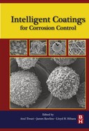
Naturally occurring or previously synthesized mesoporous or hollow micro- or nanoparticles are used for the preparation of this containers type. Several examples of micro-and nanoparticles commonly applied for this purpose are presented in the Figure 8.2.
Regardless of whether the ceramic particles are of artificial or natural origin and independent of their chemical nature, the extended porous core of these particles can serve as a robust scaffold on the next steps of containers assembly. Simultaneously, this spongelike reservoir can be loaded with various active compounds, in our particular case, anticorrosion coatings, with diverse corrosion inhibitors. The loading capacity is determined by the total volume of cavities, gaps, or pores available and can vary in the range between ~ 15 vol% for halloysite nanotubes (HS) and nearly 70 vol% for the silica nanoparticles with the highest porosity.
Halloysites nanoparticles represent one particular type of naturally occurring aluminosilicates with the average composition (Al2Si2O5(OH)4·nH2O). In contrast to kaolin and many other aluminosilicates, halloysite nanoparticles have the shape of tubes (Figure 8.2a) with the typical average length between 2 and 5 micrometers and 50 and 15 nm for the outer diameter and for the diameter of the hollow cylindrical cavity along the particle major axis, respectively.92 It is suggested, that this tubular shape of halloysite particles can to be caused by an irregular replacement of Al3 + by Fe3 + in the octahedral positions (3-10 wt.% of Fe2O3) due to geochemical processes in the earth’s crust.93
Unlike naturally occurring halloysites, spherical silica nanoparticles with much higher porosity can be prepared by the surfactant-templated polycondensation method. Size of these particles, their morphology, as well as the size distribution and structure of pores are determined by the type of the soft template applied in the synthesis (surfactant micelles or emulsion droplets) and by the physicochemical conditions in the system controlling the kinetics of hydrolysis and polycondensation.
When micelles of the cationic surfactant cetyltrimethylammonium bromide (CTAB) were chosen as template particles distributed in a sodium hydroxide solution, the hydrolysis of the subsequently added tetraethoxysilane (TEOS) and following gradual polycondensation of arising silanol molecules on the micellar templates led to the so-called spherical mesoporous silica (SMS) nanoparticles (Figure 8.2b). SMS particles have well-expressed, two-dimensional, hexagonally arranged cylindrical pores with the diameter of 3.5 nm and demonstrate very high values of the specific area and the total pore volume, 1000 m2/g and 1 cm3/g, respectively.
In the case of initial premixing of TEOS and CTAB, subsequent dispersion of this mixture in a water-ethanol medium, and raising the pH value in the continuous phase of the resulting emulsion to 11.5 with ammonium hydroxide, the formation of spherical hollow silica (SHS) nanoparticles was observed (Figure 8.2c). This type of silica nanoparticles does not show any structural order of pores, but has a quite dense shell and a highly porous inner cavity. The average pore diameter of these particles, their specific surface area, and the total pore volume demonstrate, however, values quite similar or even equal to those for SMS nanoparticles—3.5 nm, 1000 m2/g, and 0.9 cm3/g, respectively.
Another example of artificial porous ceramic nanoparticles, preliminary prepared for containers cores, are the nanoparticles of the mesoporous titania (TiO2). These particles are synthesized via heterophase oxidation of titanium carbide (TiC) micron-sized powder by the concentrated nitric acid. Subsequent multiple washing with H2O yielded (Figure 8.2d) the titania nanoparticles with average size of 400 nm and the moderate polydispersity (PDI = 0.35). These spongy ceramic scaffolds have a quite broad pore size distribution, with the mean value of 10 nm and a considerable total pore volume of about 0.35 cm3/g, which allow the sufficient loading of containers with various corrosion inhibitors.
Several kinds of mesoporous silica micro- or submicroparticles which can be immediately used for the fabrication of microcontainers are nowadays available on the market for reasonable prices. For instance, Figures 8.2e and f show two sorts of such particles, with the average sizes of 3.7 μm, but very high total pore volume of 2.0 cm3/g as well as of 500 nm and 0.75 cm3/g, respectively.
In connection with the characterization of ceramic core porosity, the question arises: what degree of porosity is enough to incorporate the inhibitor amount, sufficient for the effective corrosion protection?
Using the same formalism as at the derivation of Equation (8.7) and following discussion, let us imagine a microcontainer on the basis of the spherical porous ceramic core with the radius of 1 μm and volume fraction of pores of 20 vol%. Assuming further that only a half of this volume may be loaded with the inhibitor released upon coating damage, the volume of efficient inhibitor loaded in a single container becomes

Following the previously introduced (page 8) typical values for the density ρ, molecular weight Mw of inhibitor and its saturation adsorption Γmax on the surface of metallic substrate of 1 g/cm3, 500 g/mole, and 5 × 10− 6 mole/m2, respectively, the maximal area of substrate that can be protected by inhibitor released from this microcontainer can be estimated as

This area corresponds to the area of a square with the side length of 40 μm. One thousand of these containers can already protect an area of 1.6 × 10− 6 m2 which can be imagined as area of the scratch with the length of 16 mm and width of 100 μm, that is, as area of a quite common almost macroscopic defect occurring in the practice. Ratio of the total volume of these containers to the scratch volume can give the necessary volume fraction of containers providing the full protection of this scratch. Assuming again an organic coating with the thickness H = 70 μm, this fraction can be estimated as ~ 0.37 × 10− 4, that is, even at such a very low containers fraction the effective protection of substrate can be achieved. Of course, the presented numerical estimation of the inhibitor load capacity for containers with the porous ceramic core is quite simplified, but even in this case it demonstrates how efficient can be the application of these containers in the new anticorrosion organic coatings.
Next important step in the preparation of containers described in this section consists in the soaking of the chosen active agent or inhibitor into the pores or cavities of the container ceramic core (loading of the core). For this purpose, the corresponding porous or hollow micro/nanoparticles are added to the concentrated solution of the inhibitor in an appropriate solvent or to the pure inhibitor (if an inhibitor is a liquid) and this mixture is then subjected to the multiple cyclic vacuumization in a desiccator.71 The applied procedure provides the significant acceleration of the solution penetration and uptake in the especially narrow pores normally sealed with the tiny gaseous stoppers (nanobubbles) and enhances finally the amount of the inhibitor loaded in the containers. Moreover, the confined volume of narrow pores lead to the considerable decrease of the mobility of inhibitor molecules, which contribute as a consequence to the essentially extended release time for inhibitor impregnated into porous core and make therefore the release more sustained.
This peculiarity of the inhibitor molecules constrained in the confined volume of pores was used recently94 for the preparation of the self-protecting anticorrosion coatings for the aluminum substrate where the remarkably slower kinetics of the inhibitor release was observed for the larger core particles possessing the longer pores and providing more interaction sites between inhibitor molecules and pores walls. This prolonged release enabled the good long-term corrosion inhibition also for the protective organic coatings with the mesoporous nanocontainers without any polyelectrolyte or polymeric shells.
An important precondition required for the successful impregnation step is at least a good or, better yet, a complete wetting of particles material with the corresponding solution or liquid inhibitor. Thus, a thorough selection of a proper solvent with the good wetting ability to a specific ceramic material forming the core of container and simultaneously with the excellent solvency for the chosen inhibitor is necessary for the high efficiency of containers loading. Typically, high loading values of ceramic mesoporous containers with the inorganic inhibitors are attained from their aqueous solutions whereas organic inhibitors are less water-soluble and can be essentially better loaded from organic solvents of intermediate polarity such as short-chain alcohols, ketones and esters. Some examples of inhibitor loaded hollow or mesoporous cores particles discussed previously are presented in Figure 8.3.

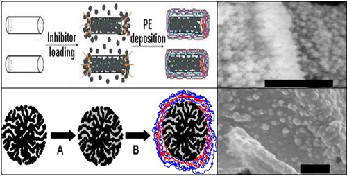
The final stage of containers assembly procedure is the layer-by-layer (L-b-L) alternate adsorption of opposite charged polyelectrolytes onto ceramic cores for the formation of PE shells around them. Cationic polyelectrolytes such as poly(diallyldimethylammonium chloride), PDADAMAC; polyallylamine hydrochloride (PAH); polyethylene imine (PEI) and anionic ones like poly(sodium 4-styrene sulfonate), PSS; polyacrylic acid (PAA); poly(methacrylic acid), PMA, can be mentioned as typical individual building blocks for the shell assembly where specific properties desired for a certain shells of future containers can be varied using different combinations of corresponding polyelectrolytes. Schematically, the process of containers build-up and its last step—the L-b-L polyelectrolyte deposition—is demonstrated in Figure 8.4. Amount of deposition and washing steps between the changes from cationic to anionic polyelectrolyte depends on the desired thickness of the shell to be created and on requirements to its final composition.
An envelope formed by polyelectrolyte multilayers around loaded ceramic porous or hollow container core significantly decelerates or almost completely stops the premature leakage of the inhibitor from the container. Moreover, utilizing a certain combination of polyelectrolytes for the shell assembly can provide it special sensitivity to the pH changes in the local surrounding; this factor can also be used as a specific trigger for the controlling of shell permeability or for the containers opening. The creation of such pH-sensitive shells of micro- or nanocontainers can particularly be achieved by deposition of weak cationic or anionic polyelectrolyte in alternation with strong oppositely charged polyelectrolyte. Both types of polyelectrolytes are almost fully dissociated in the neutral pH range and attract each other electrostatically in the container shell. This complete charge compensation within the shell leads to its neutrality and quite high density, especially in the dried state.
In the case when a weak polyelectrolyte is included in the shell composition, it becomes less dissociated in vicinity of either its pKa or pKb value depending on the acidic or basic character of this weak polyelectrolyte. As a consequence, the shift of pH value toward basic (for a weak cationic polyelectrolyte) of acidic (for a weak anionic polyelectrolyte) leads to the distortion of the charge compensation in the container shell and finally to its swelling due to electrostatic repulsion between individual layers. The opened state of containers is then achieved.
Usually, the onset of corrosion and further development of this process leads to the local pH changes that can be remarkable nearby the cathodic or anodic sites on the substrate. The corresponding specific sensitivity of containers shells converts this effect accompanying corrosion into a trigger for the opening of containers and for the release of the encapsulated inhibitor on-demand. Thus, the protective coating with embedded containers of this type demonstrates self-protecting anticorrosion functionality.
8.3.3 Containers with ceramic core and stimuli-responsive stoppers at the pores endings
The main component of this type of containers is almost identical to the one described in the previous paragraph: This is a porous or a hollow ceramic core of micro- or nanodimensions which has also to be initially impregnated with the corrosion inhibitor or other active agent. Only one specific feature here is of higher importance than for the abovementioned containers with ceramic core and polyelectrolyte shell—even in the case of a core with the hollow interior, the presence of small, through pores in the shell of this ceramic particle is essential for the build-up of this containers type (Figure 8.5). Firstly, these pores are necessary to load the inner part of the porous or hollow ceramic particle serving as a containers core. Again, being immersed into the liquid to be loaded, the particles have to be subjected to multiple vacuum cycles. After an appropriate uptake of the substance to be loaded is accomplished, the last stage of containers preparation is commenced. In contrast to the ceramic containers with the continuous polyelectrolyte multilayer shell, no enclosure of entire core particle is performed to isolate the container load from the surrounding medium and to prevent its premature release from containers. To attain the closed state of containers, the outer endings of pores in the ceramic porous or hollow particle are sealed with the insoluble stoppers made of substances that are the products of chemical or physical interactions between encapsulated corrosion inhibitor or solvent/dispersing agent and an additional external compound. For example, these stoppers can be made of ionic complexes or aggregates arising as a result of interfacial physical processes, such as interfacial precipitation, coacervation, or gelation. Therefore, the second important feature of pores is their role of “holders” for the stoppers formed at the pores outlets. The size, tortuosity, and the surface chemistry determine the ability of pores to be successfully sealed by a certain type of stoppers. Sometimes, an additional stabilizing of the pores openings or the chemical modification of their surface is necessary.95

The release of the encapsulated inhibitor toward the containers exterior can be on-demand switched on by several triggers that are, again, either the factors causing corrosion or the factors arising as a consequence of the corrosion process. As most typical triggering factors a change of pH, concentration of specific ions, ionic strength, or temperature can be mentioned. Local changes of these parameters nearby of containers in the closed state cause the swelling or dissolution of stoppers and therefore the opening of containers leading to the stimuli-responsive release of inhibitor or other active agent.
The simplest realization of this idea was recently reported by Abdullayev et al.96,97 where the halloysite nanotubes were employed as core particles. Here, the hollow lumen inside halloysites was simultaneously used as a single big pore for loading and then for the sealing of its outer ends with the stoppers. After the halloysite nanotubes were filled with the corrosion inhibitor BTA, the endings of tubules were closed by the insoluble stoppers, preventing the spontaneous release of the enclosed inhibitor. The formation of the insoluble complexes between BTA and bivalent copper cations was utilized for the nanocontainers sealing. The stimuli-responsive opening of containers was carried out by the addition of a concentrated ammonia solution to the aqueous suspension of containers. Due to formation of very stable, but soluble copper-ammonia complexes and because of pH increase leading to the formation of the anionic form of BTA, the stoppers were irreversible removed and the entrapped BTA was released in the containers’ exteriors. The subsequent introduction of these containers in the organic coatings for the corrosion protection of copper and aluminum showed their considerably better and sustained anticorrosion performance as compared with standard ones. Later, the corresponding U.S. patent application98 was made on the basis of this material.
More recently, the extended concept of these containers was also applied as a patent.99 In this patent, not only cylindrical hollow halloysites were proposed as containers cores, but also many other types of mesoporous or hollow ceramic micro- and nanoparticles. Moreover, various possible chemical as well as physical mechanisms for the stoppers creation were shown along with the inhibitor complexation reaction.
The possibility to utilize the different chemical mechanisms of stoppers opening was demonstrated very recently for the mesoporous silica-based nanocontainers with pores sealed by the insoluble complex between copper ions and BTA.95 Two external factors—the decrease of pH value below 5 and increase of sulfide ions concentration in the exterior solution led to the decomposition of copper-BTA complexes and to dissolution of stoppers followed by the release of active agents such as inhibitor BTA or antibacterial agents benzalkonium chloride or triclosan. By the incorporation of containers loaded by the corresponding agents into the coating matrix, the protective organic coatings with the enhanced anticorrosive, antibacterial, or multifunctional performance were prepared.
8.3.4 Containers on the basis of direct or inverse emulsions
As can be seen from previous sections, preparation of containers based on the use of ceramic hollow or mesoporous micro- or nanoparticle as scaffold and impregnable container core is a multistep process. Loading capacity and the number of loading cycles depend on the porosity of the scaffold as well as on the pores size distribution and can be additionally complicated in the case of narrow pores. This procedure may become even more complex when the containers load and containers core are composed of the substances with essentially different polarities. Furthermore, the polarity mismatches between core and dispersion medium where the containers were initially dislocated can make the total procedure overcomplicated.100 Together with at least two-step deposition of PE shells of containers, the entire fabrication of this containers type is not always simply and economically sound enough.
On the contrary, the paradigm in the preparation of nano- or microcontainers based on the utilization of emulsion as a starting point reveals a number of advantages over the techniques dealing with the particulate porous or hollow cores which were discussed above. Most important, the emulsion-based concept is the straightforward one where the droplets of emulsions play a twofold role: as soft (liquid) template particles and as loaded cores of the containers to be prepared. This simultaneous multipurpose use of emulsion droplets allows the significant reduction of number of stages during the containers fabrication. The second big advantage in using an emulsion as an initial system for the containers preparation is the liquid state of both the dispersion medium and dispersed phase at the beginning of assembly. First, this reduces significantly the amount of energy, that is, comminution work that has to be applied for the preparation of the colloidal system, especially in the presence of surfactants decreasing additionally the interfacial tension. Second, the liquid state of the dispersed phase facilitates the exact regulation of concentrations of all components and enables not only the fine adjustment of the active agent content and its distribution in the container, but also the precise control of containers size distribution by means of hydrophobes and surfactants.
Another benefits connected with the emulsion route for the containers preparation are the possibility to prepare containers with core/shell morphology and encapsulation of liquid ingredients. This situation may, for instance, frequently occur at the preparation of containers for biomimetic self-protecting anticorrosion coatings where the liquid encapsulated in containers resembles a biological liquid first of all blood in the skin. Thus, in case of destructive external impact, the strong immediate feedback of this coating will be achieved.
Obviously, the fabrication of oil-in-water (O/W, direct) or water-in-oil (W/O, inverse) emulsion serves as a springboard for all specific realizations of the emulsion-based concept. Thus, the liquid/liquid interface between dispersion medium of an emulsion and the plurality of droplets constituting its dispersed phase or this plurality itself functions as locus in quo where the formation of the container proceeds. A broad variety of techniques yielding finally the micro- or nanocontainers may be grouped into two wide classes depending on the nature of processes leading to the containers formation: (1) approaches using the physical phenomena for their creation and (2) techniques utilizing different chemical reactions at the interface of emulsion droplets or in-situ reactions in their bulk with eventual subsequent merging and segregation of the growing prepolymers at the interface (Figure 8.6).

This general classification is considered in more details in the next sections of this chapter on the basis of several types of containers prepared by the particular methods from these two groups. Concrete containers taken as corresponding examples will be used to discuss the methods applied for their preparation, mechanisms of their formation, and advantages and drawbacks in order to provide the self-protecting anticorrosion coatings the abilities to mimic the active feedback properties of living matter.
8.3.5 Containers based on the interfacial physical phenomena
8.3.5.1 Containers obtained by means of solvent induced interfacial precipitation
At the application of this method for the preparation of containers, the emulsion droplets serve as soft template particles at whose interface the component forming the shells of the future containers starts to precipitate because of changes in the physical or chemical parameters (composition) in the system. The same droplets contain also the substance to be loaded into containers and function therefore as their future cores. The shell-forming component is at the beginning completely dissolved in the emulsion droplets and both phases of this disperse system (emulsion) remain initially homogeneous. Several changes occurring in the system can disturb the solubility of the shell-building component and lead to start of its precipitation.
In the simplest case, changes in only one physical parameter of the system such as temperature can cause a serious lowering of the miscibility of the shell-forming component with other components in one phase of the two-phase disperse system leading to its precipitation at the droplets interface.
The decrease of the solubility of the shell-forming compound with subsequent precipitation can be also induced by changes in the phase composition—either by removal of the solvent having a good solvency for this compound (further—“solvent”) from the system or by addition of the solvent possessing a poor solvency for it (further—“nonsolvent”) to the system. Since the dispersed phase is a nonautonomous one, the phases are unequal against the independent changes of their compositions. If the shell-forming component is initially dissolved in the dispersion medium, its solubility there could be distorted almost without any effects on the composition of the dispersed phase. Moreover, a precipitation from dispersion medium is additionally favored by the presence of the emulsion droplets according to the heterogeneous nucleation mechanism that proceeds at their interface. Typical processes leading to the interfacial precipitation from the dispersion medium are evaporation of the solvent from this phase or its dilution by the nonsolvent, that is, solvent evaporation-induced precipitation (Figure 8.6), or dilution-induced precipitation.
In the spatially opposite case, precipitation starts from the interior of emulsion droplets, and triggers analogous to these for the dispersion medium can only be activated by the involving of the surrounding dispersion medium. Therefore, the solvent or nonsolvent, respectively, should at least be sparingly soluble also in the dispersion medium of the emulsion to be transferred through it from/to the emulsion droplets with the initially dissolved shell-forming component. Interfacial precipitation from the dispersed phase can additionally be influenced by curvature and confined character of its particles.
In the end, the formation of either containers with the core/shell morphology and liquid core or compact solid containers is attained.
Micro- and nanocontainers for the self-protecting anticorrosion coating containing the water-repelling agent sodium docusate (AOT) were prepared in our group,101 exploiting the solvent evaporation-induced interfacial precipitation in an O/W emulsion. The oil phase of the O/W emulsion was prepared by the mixing of water-immiscible dodecane with ethyl acetate (EA) sparingly soluble in water at the components ratio 5:9. In this composite solvent, ~ 9.5 wt.% of polystyrene (PS, Mw = 34 KDa) and 5 wt.% of sodium docusate, related to the total oil phase composition, were dissolved. Phosphate buffer solution with pH 7 saturated by EA at normal conditions was used as an aqueous dispersion medium of the emulsion. To this solution, 135 mg of nonionic surfactant Triton X-100 was added as emulsifying agent. Then, 10 v/v% rough O/W emulsion was prepared by means of Vortex-shaker (stage 7, for 1 min) and processed finally for 3 min with the high speed rotor-stator homogenizer Ultra-Turrax (IKA Werke, Staufen, Germany). After that, this emulsion was either left for the EA evaporation under the fume hood with continuous stirring at 150 rpm for 12 h or, to accelerate the removal of this solvent, firstly diluted ten times with Milli-Q water and then treated by the dry nitrogen bubbling for 5 h. Volatile EA was completely evaporated and an aqueous dispersion of PS micro- and nanocontainers containing a solution of AOT in dodecane was obtained. The zeta-average size of containers measured by DLS intensity (zetasizer Nano ZS Malvern, UK) was 1570 nm with PDI = 0.8 reflecting the strong polydispersity of containers visible also on the qualitative level in the Figure 8.7. Such a broad containers size distribution is a typical consequence of the emulsion preparation by means of a high speed rotor-stator homogenizer like Ultra-Turrax. Interestingly that the containers obtained only by the gradual evaporation of EA without acceleration showed lower polydispersity with PDI = 0.6 probably because of the Ostwald ripening in the initial emulsion droplet that kept in this case their liquid state longer. Several partially deformed containers with the concavities in the shells observable in the Figure 8.7 can be considered as an indirect argument for their core/shell or multicompartment morphology. On the other hand, this containers structure may be also deduced from the very low miscibility of core material (diluted docusate solution in dodecane) with the aqueous dispersion medium.

In spite of the simplicity and relatively low costs of interfacial precipitation method in its various concrete realizations, there are also a lot of challenges and drawbacks connected with some technical peculiarities of this method and with the properties of containers obtained in this manner related to their embedding into coating matrix. Solvents used for the dissolution of shell-forming component(s) have to be either completely or at least sparingly soluble in the dispersion medium, most often aqueous one. These solvents should be also volatile enough to assure a reasonable time of complete evaporation and formation of the container shell. Therefore, the application of this method in both solvent evaporation-induced precipitation and dilution-induced precipitation types will lead to serious amounts of environmentally dangerous wastes such as volatile organic compounds (VOC) or VOC-contaminated water, especially when upscaled to the industrial extent. Because of such environmental concerns, the industrial realization of the interfacial precipitation method may be additionally complicated by the necessity to install quite expensive recycling set-ups.
Another problem is that polymers used for the formation of containers shells are the preformed polymers, which should be well-soluble in several solvents of intermediate polarity ensuring the good miscibility with both aqueous and oily phases. Thus, the relatively low cross-linking degree of polymers employable for this purpose is required. However, the high solubility of shell-forming polymers in the solvents of moderate polarity excludes automatically the incorporation of containers made of these polymers by interfacial precipitation in the coatings on the basis of organic solvents and restricts their use only to water-borne coating formulations. Moreover, even in this case, the coating formulations with relatively high curing temperature can also be a subject of doubt as the low cross-linking degree of polymer will cause its melting already on the curing step with subsequent destruction of containers.
8.3.5.2 Containers prepared by the use of layer-by-layer (L-b-L) polyelectrolyte interfacial adsorption
Notwithstanding that the L-b-L interfacial adsorption method became well-established worldwide in cases of plane solid102 and colloidal solid103 templates in the last three decades, its extension to the liquid colloidal templates (emulsion droplets) was elaborated not so long ago. Several details of this technique were partially used already in some works issued in the middle 2000s.104–106
These attempts were, however, seriously restricted either by employing specific chemicals or by application of unique preparation conditions. So, Tjipto and coworkers106 have used the special substance (4′-pentyl-4-cyanobiphenyl) forming nematic liquid crystals as material for the droplets of O/W emulsion to be encapsulated. At the encapsulation of various food-relevant emulsions, both amounts of hydrophobic bioemulsifiers and the preparation conditions used evidences that the initial solid or solidlike layer was formed at the interface before the container shell formation by L-b-L polyelectrolyte deposition was started.104,105
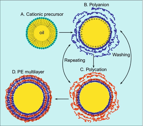
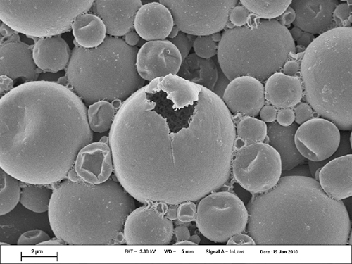
Universal approach to the preparation of loaded micro- and nanocontainers based on the direct emulsion encapsulation by polyelectrolyte L-b-L adsorption was developed only recently.107 Using this approach, the liquid colloidal templates (droplets of O/W emulsion) were composed of water-immiscible substance dodecane. To stabilize the dispersed phase of initial emulsion and to ensure the significant interfacial charge of droplets for the beginning of polyelectrolyte adsorption, the oil phase was doped by small amount of cationic surface-active precursor Dioctadecyldimethylammonium bromide (DODAB). Because of dodecane’s very low solubility in nonpolar solvents, 30 v/v% of chloroform was added to dodecane in order to improve the precursor solubility in the oil phase. The droplets of O/W emulsion, however, did not contain any detectable traces of chloroform during the polyelectrolyte deposition steps because of its considerable solubility in the aqueous media. Colloidal stability of initial emulsion was achieved due to a concentrated monolayer of strongly positively charged DODAB (zeta-potential was about + 90 mV) at the surface of each droplet. The L-b-L assembly was done by the subsequent adsorption of oppositely charged polyelectrolytes from their concentrated (20 mg/ml) aqueous salt-free solutions. The creamed upper layer of the positively charged initial emulsion was added dropwise to the oppositely charged solution of PSS upon continuous stirring, ensuring its good adsorption with the subsequent overcharging of the droplets interface. The excess of the remaining free polyelectrolyte was washed out by pure Milli-Q water. The second encapsulation step was done in an aqueous solution of cationic PE PDADMAC or PAH in the same manner (Figure 8.8). The further repetition of the alternating adsorption steps leads to the formation of containers with desired shell thickness depending on the particular final demand. Resulting containers had Z-average size of 4.2 μm and were quite monodisperse (PDI = 0.32). The dried droplets of O/W emulsion encapsulated by the L-b-L interfacial adsorption technique are presented in the figure. Since the procedure of drying leads, in the case of PE oil-filled containers, to their collapse, especially on the steps connected with the preparation of SEM samples, the oily containers cores cannot be kept intact, and only wrinkled polyelectrolyte containers shells are observable (Figure 8.9), supporting the polyelectrolyte multilayered shell assembly around O/W emulsion droplets.

Following the proposed paradigm for the straightforward preparation of the emulsion-based polyelectrolyte containers107 further progress in this field was achieved.108,109 Wackerbarth et al.108 reported polyelectrolyte microcontainers on the emulsion basis with six layers of biopolyelectrolytes for the potential application in the food industry. The authors of Ref. 109 have presented the successful polyelectrolyte encapsulation of highly unstable polyunsaturated natural oils for the purpose of storage and degradation protection by introducing the natural antioxidant compound (tannic acid) as a shell constituent in alternation with the biocompatible oppositely charged polyelectrolyte.
Container prepared via polyelectrolyte L-b-L direct emulsion encapsulation technique can be envisaged as quite applicable in several types of protective coatings, especially water based, imparting to them some unique functionalities independent of the nature of components encapsulated in the core. This can be achieved due to the many polyelectrolytes available for L-b-L container shell assembly. Purposeful choice of polyelectrolytes for the containers shells allows their opening by numerous environmental or artificially introduced triggers such as temperature,110 pressure,111 changes in pH,112 ionic strength, electrochemical potential, and therefore enables the specific stimuli-responsive protective ability of coatings carrying these containers.
Nanometric accuracy provided by polyelectrolyte L-b-L deposition on the each step of the container build-up allows very fine adjustment of their size and the shell thickness that also can be of high practical importance in many research and industrial fields.
On the other hand, some drawbacks of polyelectrolyte containers obtained by the L-b-L interfacial adsorption should be also mentioned here making their utilization in many types of self-protecting coatings problematic. Even at deposition of polyelectrolytes with lowest Mw the permeability of shell for low-molecular agents loaded into containers remains high disabling the possibility of sustained release for these substances and use of such type of containers in the media with good solvency for the core material. Low mechanical stability of the polyelectrolyte shells at any reasonable number of polyelectrolyte layers in the shell is the other source of trouble. It can be significantly improved by the increase of L-b-L deposition steps and subsequent annealing at higher temperature,110 such an overcomplication makes the fabrication costs rise and thus is unacceptable for many potential application fields. At the same time, the use of soft emulsion-based containers with L-b-L polyelectrolyte shells is imaginable in the water-borne coating formulations with the quite mild curing conditions and ductile coating matrices.
8.3.5.3 Containers on the basis of irreversible interfacial attachment—formation of Pickering emulsions
Noticeable phenomenon of emulsions stabilization due to spontaneous attachment of the partially hydrophobic/hydrophilic micro- or nanoparticles at the O/W or W/O interface underlies this method of preparation of emulsion-based nano- and microcontainers.
This “strange” behavior of such particles is known since the beginning of twentieth century113,114 and can be strictly described in terms of particle energy change at its transition from the bulk location to the interface115:
Thermodynamically, even in the case of small nanoparticles, this transition is practically irreversible because of the huge depth of the potential energy of the particle located at the interface and is therefore commonly called not “adsorption” but “attachment.” Due to these reasons, the partially hydrophobic/hydrophilic particles form spontaneously a tight mono- or even multilayer at the emulsion droplets interface and act as building blocks for the containers shells. Again, the emulsion droplets serve as a template for the formation of the particulate shells and work at the same time as reservoirs for the loaded active agent.
The interfacial activity of particles can be an intrinsic property of them connected with their specific affinity to certain types of solvents. In this case even the pristine particles with unmodified surface are able to concentrate at the interface between droplets of this solvent and the external continuous phase.116 However, this peculiarity is more frequently imparted to the particle by its surface modification using various types of surfactants117,118 bonded electrostatically or covalently to the particle material.
Electrostatic mechanism of the modification does not presume the formation of the proper chemical bonds between surfactant molecules and particle surface, but is rather a result of the equilibration of the complex physical interactions between these molecules, particles, and surrounding medium (solution). Therefore, the small amounts of free surfactant molecules always persisting in the system can occasionally interfere with the corrosion inhibitor or other protective agents in the core-forming emulsion droplets and impair the mechanism of the interfacial particle attachment. To avoid this undesired situation, the thorough selection of appropriate nonreacting and noninteracting surfactants and protective components should be made before fabrication of containers. The indicated problem will, however, not arise at all when inhibitor molecules possess by themselves the certain surface activity and can therefore simultaneously cause the partial hydrophobic modification of the particle surface. Many corrosion inhibitors are weak organic acids, bases, or amphoteric compounds having functional groups partially or fully ionized in a certain pH range and therefore becoming hydrophilic. In the case when residual organic moieties of inhibitor molecules are hydrophobic enough, the entire molecule will demonstrate the amphiphilic behavior in the same pH range, that is, will act as a surfactant. Haase et al. utilized the corresponding ability of the amphoteric corrosion inhibitor 8-hydroxyquinoline (8-HQ)119 to become considerably protonated at the pH < 5.5 (pKa = 5.13) and to be adsorbed electrostatically on the surface of negatively charged silica nanoparticles (Ludox TMA) in order to make them partially hydrophobized and therefore interfacially active. These particles stabilize the O/W emulsion droplets forming the multilayers at their interface that can be considered as particulate containers shells (Figure 8.10). The droplets of dispersed phase are composed of Diethyl phthalate (DEP) with dissolved 8-HQ and function as containers cores with the already loaded inhibitor. The containers size distribution and the amount of nanoparticles in the containers shells are well-expressed functions of pH in the range from ~ 4.4 to 5.6. At pH 4.4 the monodisperse containers with volumetric average size of 4.5 μm and PDI of about 0.4 were obtained. This pH-dependent behavior can be related to the continuously increased interfacial activity of silica nanoparticles hydrophobized by the gradually growing amount of the adsorbed 8-HQ upon pH drop. Below the pH 4.4, protonation degree of 8-HQ and subsequently its concentration in the dispersion medium attain the values enabling the formation of an 8-HQ bilayer on the surface of silica nanoparticles. The hydrophobe-hydrophobe interaction of the overlapping aromatic rings is suggested to be a driving force for this effect. As a result, the positively charged protonated groups of 8-HQ molecules in the outer part of bilayer are oriented toward dispersion medium and re-hydrophilize the particles in the containers shells. The rapid destruction of the containers is observed in this pH region, leading to the immediate burstlike release of the encapsulated inhibitor. This pH-sensitivity as well as the mechanical rupture of containers could be utilized as triggers for the containers opening and stimulated inhibitor release when the containers become embedded in the matrix of a self-protecting anticorrosion coating.

Emulsion-based containers fabricated by means of interfacial attachment of nano- or microparticulate building blocks forming the container shell reveal several advantages in the preparation routine and in the handling that follows, fashioning them as potential candidates for the use in the various self-protecting coatings. Fabrication of micro- and nanocontainers by means of the interfacial attachment method is usually quite simple procedure that includes as a rule only two steps—(1) preparation of particles as building blocks for the shells of future containers due to their partial hydrophobization (O/W) or hydrophilization (W/O) and (2) addition of them to the two-phase system containing all components of containers during or immediately before the emulsification with subsequent processing leading to the ready containers. Sometimes this procedure can be even further simplified to the practically one-pot process.116 Because of its simplicity, this preparation pathway may often be economically sound and has a high practical relevance. Wide variety of particles of different chemical nature and of immiscible solvents with diverse polarities available facilitates an almost unlimited number of achievable containers types thus making the method very versatile. Comparing with the types of the emulsion-based containers described above, containers prepared by the interfacial attachment of particles demonstrate much higher robustness120 and are therefore more suitable for the incorporation into self-protecting coatings with hard coating matrices. However, the main problem in the application of containers prepared by interfacial attachment remains the heterogeneity of their shells comprised of many fine particles joined at the surface of each emulsion droplet to a mono- or multilayer with the lot of gaps between individual building blocks. This discontinuous structure of the container shell reduces considerably its mechanical properties, especially comparing with these of the individual particle in the shell and increases its permeability drastically. The latter could be very critical when the containers loaded with the oil-soluble protective agent are mixed with a solvent-based coating formulation able to wash out the containers load immediately after their addition into coating mixture.
To enhance the mechanical strength of containers and make them more seamless, single particulate elements of the containers shells should be locked at the interface and joined together. It can be done for instance by the local high energy treatment121 where the high intensity ultrasound was used for this purpose. The second possibility is the interlinkage of particles in the shell by the deposition of additional polyelectrolyte layers atop it. This, on the one hand, complicates the process of the containers preparation by one more step, but on the other hand can significantly improve the integrity and permeability of their shells. Moreover, the polyelectrolyte deposition could impart to shells certain additional valuable features connected with the properties of polyelectrolyte layer like selective pH sensitivity and so on. Figure 8.11 shows containers on the basis of Pickering emulsion droplets made of 1.5 M solution of 8-HQ in dimethyl phthalate (DMP) coated with three polyelectrolyte bilayers composed of pairs PAH/PSS or PAH/PAA. Alternate deposition of polyelectrolytes not only did not disturb the initial containers size distribution with volume-average size of 2.5 μm and PDI = 0.35, but also did lead to the significantly higher stability of containers that remained almost not deformed during the SEM sample preparation.

8.3.6 Containers prepared by the interfacial or bulk chemical reactions in emulsion droplets
In the chemical methods of containers fabrication, containers form in the course of a chemical reaction proceeding either at the interface between emulsion droplets and dispersion medium around them or in the droplets interior.
Following to this natural division related to the reaction location, also the containers obtained by means of the corresponding reactions could be classified in two big groups: containers prepared using the interfacial polyaddition or polycondensation reactions and containers obtained by in-situ emulsion polymerization proceeding usually in the bulk of emulsion droplets.
8.3.6.1 Containers via interfacial polyaddition/interfacial polycondensation
At the containers synthesis by interfacial reaction in an emulsion, at least one of the reactants is distributed outside droplets in the continuous phase of emulsion whereas the others are dissolved in the droplets. Initially, the reactants have sufficiently different polarities and are predominantly soluble only in one of the coexisting phases excluding their interpenetration in the adjacent phase and premature reaction between them. Moreover, reactants have to remain phase-separated all the time when reaction goes on and meet each other only at the interface of emulsion droplets. If the product of such an interfacial reaction is soluble neither in the droplets of the emulsion nor in the medium around them, containers with the core/shell morphology will be synthesized. In the more frequently arising case, however, the resulting product is soluble or swellable in the droplets of dispersed phase, and particles with the compact morphology occur.122,123 Depending on the release of low-molecular side products, the interfacial polyaddition (without side products) or interfacial polycondensation (with) reactions can be discriminated.
The encapsulation of the mixture of protective agents possessing simultaneously the functionalities of corrosion inhibitors and water repellents was carried out recently124 by the interfacial polyaddition technique for the further application in the self-protecting anticorrosion coatings. The oil phase of the future O/W emulsion was composed of mixture of two protective agents, trimethoxy(octadecyl)silane (TMODS) and trimethoxy(octyl)silane (TMOS), Poly[(phenyl isocyanate)-co-formaldehyde] trifunctional pre-polymer participating in the reaction of shell formation as well as solvent (DEP) enabling the miscibility of all components.124 This mixture was firstly dispersed in an aqueous medium by means of nonionic polymeric emulsifier polyvinyl alcohol (PVA) under intensive stirring for 3 min with high speed rotor-stator homogenizer Ultra-Turrax (IKA Werke, Staufen, Germany).
Resulting emulsion was added to the phosphate buffer solution containing the second water-soluble reactant glycerol and polyaddition reaction catalyst 1,4-diazabicyclo [2.2.2]octane (DABCO). The formation of polyurethane (PU) containers shells at the interfaces of droplets was occurred according to the following reaction scheme:
The reaction mixture was then left for 1 h at 65 °C under continuous stirring and subsequently overnight without heating and stirring for the completion of containers formation. Suspension of obtained micro- and nanocontainers was dialyzed in order to remove residual glycerol and PVA and then separated by centrifugation at 13,000 rpm. Finally, quite polydisperse microcontainers with the well-expressed core/shell morphology (Figure 8.12) were isolated.
The size distribution of resulting PU containers demonstrated two peaks representing two main fractions of containers in the mixture—one at 1.0 μm and the second one—at 5.5 μm. At the increasing of rate of the high speed rotor-stator homogenizer from 11,000 rpm through 16,000 rpm to 22,000 rpm, the area of the first peak was continuously increased with the subsequent reduction of the second one remaining, however, still bimodal. Such a bimodal particle size distribution can be considered as polymerized replica of an initial O/W emulsion predestined by its droplets size distribution125 almost always showing a high polydispersity if the high speed rotor-stator homogenizer was applied for the emulsification process. Utilization of ultrasound for this purpose leads as a rule to narrower and frequently monomodal droplet size distribution in the original emulsion.126 Application of this comminution method in the considered case of containers with PU shells was unfortunately impossible because of numerous sonochemical effects accompanying the collapse of cavitation bubbles upon ultrasound propagation. Reactive isocyanate functional groups in the pre-polymer molecules quickly underwent side reaction with water molecules and highly reactive products of the water thermolysis (free radicals, hydroxyl-carrying species, etc.).
The incorporation of a small amount of these containers into the conventional coating (~ 6 wt.% microcontainers in relation to the total mass of the dry coating) provides to itself protecting features: Being mechanically damaged, the modified coating reveals not only recovered corrosion protection at the site of scratch, but also dewetting ability for the aqueous corrosive media.
Figure 8.13a and b demonstrate example of containers obtained by the interfacial polycondensation technique. The containers presented here have silica shells and are filled with the corrosion inhibitor mercaptobenzothiazole (MBT) dissolved in the organic solvent dibenzyl ester. These two compounds along with the shell-forming component TEOS were mixed together to form the oil phase of the future emulsion. An oil phase was dispersed in an aqueous phase with pH = 11.5 using the cationic surfactant CTAB, and the resulting emulsion was then left overnight at 65 °C. Formation of container shell made of silica was achieved due to gradual hydrolysis of TEOS with the silanols as semi-products and their subsequent condensation on the surface of liquid colloidal template127:


At the end, the polydisperse submicrocontainers (zeta-average size 700 nm, PDI = 0.43) loaded with MBT (see EDX spectrum in the Figure 8.13b) were collected.
These containers can be successfully applied in the anticorrosive self-protecting coatings in cases when the corrosion is caused or followed by the pH increase. The dissolution of silica shell in this pH range can lead to the corrosion-triggered release of inhibitor.
Similarly, the containers of other composition with compact morphology were obtained for self-protection purposes by the interfacial polyaddition method. This type of containers made of polyurea and the corrosion inhibitor 2-methylbenzothiazole (MeBT) was used in the self-protecting anticorrosion coatings for the aluminum substrate.123 Formation of the compact morphology can be explained as a result of the high affinity of MeBT to the polymer network. Due to very good solvency of this liquid inhibitor for polyurea, MeBT becomes homogeneously distributed over the whole droplet volume, forming a gel with a high amount of the liquid component. At the same time, crosslinked polymer network can hold the structure of the resulting particles together, ensuring their solid state. These microgel particles combine the attractive properties of both solids and liquids, making them perfect candidates for usage in self-protecting anticorrosion coatings. The solid state of the particles ensures good mechanical stability of the resulting coating system. The liquid component (MeBT), being entrapped in the solid matrix, retains its mobility providing the coating system with self-protecting abilities. The introduction of only a few parts of the particles in an organic coating allowed the significant improvement of its corrosion protection performance, as was shown by scanning vibrating electrode technique and electrochemical impedance spectroscopy.123
Figure 8.14 shows another example of containers obtained by the interfacial polycondensation technique. These containers have polyamide shells and are filled with the corrosion inhibitor Ce(III)-tris-(bis-2-ethylhexyl) phosphate dissolved in the organic solvent dibutylphosphate. These two compounds along with the shell-forming component terephthaloylchloride (TPC) were mixed in the weight ratio 2:13:5 for inhibitor, solvent and TPC, respectively, to form the oil phase of the future emulsion. Oil phase was dispersed in the Milli-Q water using the nonionic emulsifier PVA and the resulting emulsion was then added to the second aqueous phase containing combination of bi- and pentafunctional amines—ethylenediamine and tetraethylenepentamine in the ratio ensuring the trifunctionality of the final mixture. The rapid formation of containers shells according to the reaction:
was accomplished by the release of HCl as the low-molecular side product and was therefore conducted in the highly basic medium containing fivefold excess of amines relating to the TPC amount. The obtained containers had a mean size of 6 μm and were highly polydisperse (PDI = 0.7) because of very cautious conditions during their preparation (use of high speed rotor-stator homogenizer at lowest stirring rate, short comminution time, etc.).

These containers may be promising for the applications the anticorrosive self-protecting coatings in cases when the corrosion is caused or followed by the pH decrease. The dissolution or strong swelling of the polyamide shell in this pH range will lead to the corrosion-triggered release of inhibitor.
8.3.6.2 Containers through in situ emulsion polymerization
Realization of this technique of containers preparation presumes that all reactants needed for the synthesis are contained in the emulsion droplets from the beginning. These droplets serve as reservoirs for reactants and protective agents and play simultaneously the role of liquid colloidal reactors and are only kinetically stabilized against the premature onset of polymerization reaction. After the O/W or W/O emulsion with desired properties such as stability, concentration, droplet size distribution and so on is prepared, the chemical (initiator substance, catalyst) or physical (T, UV-light etc.) triggers are activated to switch on the reaction and it runs until the attainment of the real equilibrium state corresponding to the completion of the polymerization.
The polyepoxy containers loaded with the corrosion inhibitor MeBT for the use in self-protecting anticorrosion coatings on the aluminum substrates were prepared by in-situ polymerization method101 by the following steps. The mixture of reactants needed for the formation of polyepoxy shells of containers was initially prepared of the 1:1 combination of aromatic and aliphatic epoxy-monomers trimethylolpropane triglycidyl ether and tris(4-hydroxyphenyl)methane triglycidyl ether, respectively. A 20% of MeBT related to the total mass of the mixture was then added. The final step in the preparation of oil phase of the future emulsion was the addition of the second reactant for the in-situ polymerization reaction—diethylenetriamine in the amount ensuring the slight excess of the stoichiometric equivalence with the sum of both epoxy components. The oil phase was dispersed in the 2 wt.% aqueous solution of the nonionic emulsifier PVA using Ultra-Turrax at 16,000 rpm for 5 min. The obtained O/W emulsion was then doped with a small amount of polymerization catalyst tetrabutylphosphonium bromide to increase the reaction rate to a reasonable level. The mixture was left overnight under moderate stirring to complete the polymer formation. The resulting containers are very polydisperse (see Figure 8.15), with the volume-average size of 2.3 μm (PDI = 0.96), and have obviously the core/shell morphology revealing the phase separation in the emulsion droplets in the course of the polymerization reaction leading finally to the segregation of core and shell parts of containers. Again, the significant improvement of the container size distribution by the creation of the more monodisperse initial O/W emulsion via utrasonication was not possible because of the immediate reaction of monomers with water and especially with the products of sonochemical processes. Because of presence of free amino groups in the structure of the epoxy polymer that is obtained, the containers reveal high positive surface charge (zeta-potential of about + 45 mV) and are therefore well dispersible in various aqueous media, for instance, in the water-based liquid coating formulations. Moreover, the introducing of epoxy monomers with the functional groups easily hydrolyzable in the acidic or basic medium (like ester groups) allows their opening in these media and finally acid- or base-triggered release of protective agents from the containers.

Sometimes, the combination of several emulsion-based methods of container fabrication leads to better results than the application of each of these methods alone. Solid micro- and nanocontainers for the self-protecting anticorrosion coatings were prepared via interfacial deposition of droplets-stabilizing SiO2 nanoparticles with subsequent in-situ polymerization of their liquid cores.128 Oil phase of the initial Pickering emulsion was composed either of styrene with dissolved corrosion inhibitor 8-HQ, hydrophobe hexadecane (HD) and polymerization initiator azo-bis-(isobutyronitril) (AIBN) or of styrene, corrosion inhibitor MBT, 4-vinylpyridine (4VP) as a solubilizing agent for MBT, HD, and AIBN. The weight percent ratios of all components were 193:45:10:2 or 255:90:130:20:4, respectively. The silica nanoparticles (Ludox TMA, Sigma) were used for the creation of particulate shells of the future containers. Noteworthy, that no additional steps for making silica partially hyhrophobic and therefore intefacially active were needed: 8-HQ acts as SiO2 particle hydrophobizing agent and as, simultaneously, the encapsulated inhibitor, 4VP also hydrophobizes silica, acts as a MBT cosolubilizer, and becomes copolymerized with styrene. Variation of the amount of silica introduced in the liquid/liquid system during the comminution step (ultrasonication, VCX 505, Sonics & Materials Inc. Newton, USA) allowed the size controlling of the interim containers with the oily liquid core simply by the almost complete consumption of particles due to their interfacial deposition. The higher was the ratio of nanoparticles mass to the oil volume R, the smaller were the droplets of corresponding Pickering emulsion, independent of the ultrasonication power (W = 40 W) applied to the system. The size distribution of the nanosilica-stabilized emulsion droplets was always satisfactorily narrow: at R = 0.09, the number-average size was 2.3 μm with PDI = 0.45; at R = 0.32, the number-average size was 600 nm with PDI = 0.35; and at R = 0.91, the number-average size was around 260 nm with PDI = 0.2. It is also important to emphasize here that before and during the ultrasonic treatment the system was purged for 7 min by the nitrogen flow and ultrasonication was carried out under continuous cooling in the ice bath. These measures allowed the complete avoiding the undesired premature polymerization on the dispersion step. Finally, the polymerization of the liquid cores was initiated by heating the whole mixture up to 65 °C for 24 h. These solid containers (Figure 8.16) were introduced in the conventional water-based alkyd coating formulation that was then deposited on the aluminum specimens. The coatings with entrapped containers showed considerably better corrosion resistance than unmodified ones, as was confirmed by EIS and SVET measurements (Figure 8.17).


8.4 Release of Active Agents from Containers
Release kinetics of an active agent (corrosion inhibitor) entrapped in containers is very important characteristic of them influencing strongly the rate and intensity of protective feedback of the coating in which these containers are incorporated. Of course, there are some other factors that can also affect the feedback kinetics like distribution of containers in the coating matrix, its permeability for molecules of encapsulated agent as well as for the molecules from ambient medium and so on, but the release properties of containers themselves remain the main parameters that determine their selection for the particular practical application. Basically, shell thickness and indirectly related to it permeability predestine the release kinetics from container. Both these parameters can be widely varied at the containers assembly. The precisely controlled thickness of containers shells can be designed by the exact components ratio during the synthesis of polymeric containers either via interfacial or via in-situ polymerization methods. In case of containers with the ceramic core and polyelectrolyte shell, even the nanometric accuracy is possible through the number of individual steps of alternate polyelectrolytes deposition.
Together with absolute thickness of the container shell, the chemical nature of the shell material is essential for the kinetics of release especially in regard to the chemistry of the encapsulated active agent and to the medium where the container should be then dispersed. If the product of interfacial or bulk polymerization reaction is swellable in the containers cores due to good solvency of liquid inhibitor or auxiliary cosolvent used for the homogenization of oil phase prior emulsification step, the resulting containers do not acquire the core/shell morphology but are rather compact gel particles,122,123 revealing slow and sustained release of the encapsulated substance. Solubility or swellability of shell-forming material should be also taken into account on all steps of containers incorporation in the final coating. Containers have to remain stable already on the stage of their mixing with the coating formulation (free-standing containers) and then during the subsequent application and curing steps until their exposure to the aggressive surrounding (containers embedded in the coating matrix).
To examine the influence of certain components of the coating formulation where the containers should be distributed before the application step, the release from the containers freely dispersed in the medium mimicking this solvent mixture has to be studied. For instance, the containers with ceramic cores and polyelectrolyte shells are suitable mainly for the use in aqueous coating formulations because of the polar character of their shells. In order to check how these media can influence the shell properties and therefore the release behavior of containers they were incubated in buffer solutions with different pH values and the corresponding release kinetics were investigated. The results of this study are given in Figure 8.18a showing fast and almost complete release of active agent (corrosion inhibitor BTA) in acidic and basic pH ranges. These findings are consistent with the strong swelling of polyelectrolyte complexes made of two weak polylectrolytes—basic PAH and acidic PAA in the same pH windows. Swelling of polyelectrolyte shells of containers is therefore responsible for the opening of containers and release of inhibitor at low and high pH values which can be used as triggers for the protective feedback activity of coatings containing this containers type.


In contrast, Figure 8.18b shows the example when the medium impact on the containers shells leads to the very fast release of the encapsulated active agent. Burstlike release of the antibiofouling and antibiocorrosion agent 4,5-dichloro-2-n-octyl-4-isothiazolin-3-one (DCOIT) from PU microcontainers in an ethanol medium demonstrates clearly the complete inapplicability of this containers type for use in the coating formulations with the ethanol-like media.
For containers with porous or hollow ceramic core, the shape of hollow lumen and pore size distribution are additional factors that contribute significantly to the final rate of release. Figure 8.18c demonstrates that in the case of especially high porosity of the core and very fine pores (containers made on the basis of SHS silica nanoparticles), the release of the loaded substance from the core may last a considerable time. Changes in the pH value of the surrounding medium affect the release kinetics additionally because of the corresponding changes in the surface charge of the ceramic core and amphoteric character of the loaded inhibitor 8HQ.
Combination of containers providing both fast and continuous slow release in the same coating matrix seems to be especially suitable for an optimal protective performance of this coating. Initial strong burstlike release at the site of the damage ensures the high local concentration of inhibitor or other protective agent leading to the immediate creation of its protective layer on the metal surface whereas the following gradual release of small portions of inhibitor over long-term period provides the sustainability of the protection.
8.5 Distribution of Containers in the Matrices of Novel Protective Coatings
Homogeneity of containers distribution in the matrix of the protective coating is another very important parameter that can strongly influence not only the stimuli-responsive ability of novel coatings, but also affect their barrier properties. Traditionally, the proper size of containers for the incorporation in a coating is believed to be optimal if they have the size of about 10% as compared with the thickness of the coating layer in which they are embedded. This ratio between coating and containers dimensions ensures the maintenance of the coating integrity also after incorporation of containers including the most critical situation when some small aggregates of containers will be formed during some steps of the coating application or coating processing. However, even in almost ideal case of small and nonaggregated containers, the formation of local areas with the enhanced concentration of containers within coating matrix may lead to the deterioration of barrier properties of this coating and subsequently to the failure of its anticorrosion performance.129 Moreover, location of containers predominantly in a certain part of the coating matrix can also influence the response rate of novel coating to the damaging impacts. As it was shown very recently,130 increasing the distance between containers localization and metal surface to be protected led to better barrier properties, but worsened the active corrosion inhibition. The opposite situation when containers are located close to the substrate caused the decrease of passive protection of the coating.
Distribution of containers in the matrix of the cured coating is closely related to their dispersibility in the initial coating formulation. This characteristic, in turn, depends on the interplay between the interaction of containers with themselves (cohesion) and with solvent components of the coating formulation (adhesion). If the work of adhesion exceeds the work of cohesion the wetting of containers by the coating formulation medium is energetically disadvantageous and they tend to form aggregates. In the best case of lower adhesion work, the good wetting of containers is achieved and they may be dispersed well in the coating formulation. Other important preconditions for stability of containers dispersion are electrostatic or steric barriers around containers preventing their aggregation. On the other hand, such factors as high density difference between material of containers and the formulation medium as well as presence of other particles (in the worst case—of opposite charge), such as particles of the color pigment, can lead to the destabilization of the entire coating formulation even prior application and then to the very inhomogeneous distribution of containers in the matrix of the cured coating.
Creation of electrostatic or steric barriers protecting containers from the premature aggregation can be performed by means of their surface modification. Most frequently, substances having the surface activity are used for this purpose including ionic, nonionic and polymeric surfactants. Modification of containers surface by surfactants can also essentially improve their wettability by the formulation medium providing their better dispersibility in this formulation. In this manner, the stable dispersions of quite polar containers may be prepared not only in polar (aqueous) media, but also in the media with much higher hydrophobicity.131
Containers with polymeric shells of significant polarity such as PU, polyurea (PUa), and polyamides, are well-dispersible in media with high to moderate polarity because of their essential surface charge stabilizing containers from coagulation. These containers can be successfully introduced into water-based coating formulations as for instance shown in Figure 8.19a and b. Core/shell containers with the PU-shells and DCOIT loading for the self-protecting coatings against biofouling and biocorrosion are presented in the Figure 8.19b as already embedded into the polyepoxy coating matrix. These containers were prepared similarly to the pathway described above for the alkoxysilanes filled PU containers. Only the difference was that instead of alkoxysilanes mixture, the dispersed phase of the initial O/W emulsion contained about 55 v/v% of 10 wt.% solution of DCOIT in the mixture of octyl- and nonylbenzene.


At the same time, the polar nature of solvent-free powder coatings (polyester and polyepoxy) allowed the homogeneous distribution of not only containers with PUa shells, but also of much more polar halloysites-based containers (Figure 8.19c and d, respectively).
8.6 Protective Performance of Container-Based Organic Self-Protecting Coatings
Self-protecting functionality of novel coatings is determined by the type(s) of active agent(s) loaded in the containers that are incorporated in the coating matrix. Thus, first of all, not only anticorrosion, but also antifouling, dewetting, and many other types of active functional coatings, are realizable. Because of the special construction of containers shells, their opening is triggered by the factors accompanying the onset or development of destructive events, such as corrosion and biofouling. When the coating of a container is damaged as a result of a destructive attack, nearby containers also become mechanically and/or chemically affected. Therefore, the release of the protective agent happens exactly on the damaged or affected site, only on demand and just in the quantity not exceeding the amount really necessary for the termination of destructive processes. This “smart” behavior of new active coatings leads to very slow depletion of the active agent, and a very sustained protective performance is achieved compared with conventional coatings. Moreover, through the fact that some consequences of a certain deterioration process can act as triggers for the release of active agents and finally for the return of the coating to the almost fully recuperated state, the self-recovering of the main protective function of the coating is attained.
Specimens made of AA2024 aluminum alloy were coated with water-based two-part epoxy paint formulation containing 10 wt.% of inhibitor-loaded micro- or nanocontainers. The anticorrosion performance of these coatings was then compared with the performance of standard coating possessing 15 wt.% of inorganic anticorrosion pigment by means of a filiform corrosion test according to DIN EN 3665. Results of this test are presented in Figure 8.20 and reveal that not only formulation with nanocontainers based on the mesoporous silica nanoparticles, but also core/shell microcontainers with an epoxy shell and inhibitor-rich core have better performance than the standard formulation.

The halloysite-based nanocontainers embedded in an acrylic coating improved its corrosion protection performance significantly compared with standard coatings used previously for the same purpose. The results of copper accelerated acetic acid salt spray test (CASS-Test) performed in accordance with the specifications of ASTM B368 showed essentially longer maintenance of coating integrity in the area around the artificial scratch and at the cut edges as well as much lower delamination for the coating containing inhibitor loaded halloysites (Figure 8.21). This enhanced anticorrosion efficiency of novel coating was achieved due to lower depletion of inhibitor from tubuli-shaped containers possessing PE shells, making the inhibitor release much more sustained.

Figure 8.22 shows two another successful applications of inhibitor loaded halloysite-based nanocontainers. Powder-coated steel specimens were subjected to a neutral salt spray test (NSS-Test) according to ASTM B117 for 500 h. As can be seen, independent of the chemical composition of the coating matrix, introduction of inhibitor-loaded nanocontainers led to significant improvement of anticorrosion performance of the coating both for corrosion development on the scratched site as well as for the extent of delamination around the scratch.

8.7 Conclusions
A novel approach based on the incorporation of active agent filled nano- or microcontainers in the matrix of protective coatings leads to the essential improvement of their resistance to various environmental attacks and to more sustained anticorrosion performance, especially combined with the traditionally proven corrosion protection solutions.
Nano- or microcontainers are a key element of the new protective organic coatings and characteristics of these containers such as composition, morphology, and size determine essentially the protective efficiency of the coating.
Environmentally friendly LDH-based nanocontainers revealed a high versatility of their structures and may have a significant potential for applications in self-protecting coatings.
Efficient and robust nanocontainers can be prepared on the basis of naturally occurring or preformed hollow or mesoporous nanoparticles with subsequent formation either of an L-b-L polyelectrolyte shell or pore stoppers sensitive to the specific corrosion related triggers.
Fabrication of polymeric and composite nano- or microcontainers via the emulsion route is other versatile approach allowing preparation of containers with core/shell, multicompartment or compact (on demand) morphology, and size in the range from some micrometers to some tens of nanometers, wide variety of loaded corrosion inhibitors both in solid and liquid state, as well as shell components for optimal incorporation in different coatings.
Embedding of containers with different active agents (inhibitors, biocides, dewetting agents, etc.) can provide not only the active coatings with single specific feedback-active functionality, but also multifunctional (simultaneous embedding of several containers types) protective coatings.