
Important Aspects Involved in Pilot Scale Production of Modern Paints and Coatings
Sandeep Rai*; Snehal Lokhandwala† * GRP Limited, 510, A Wing, Kohinoor City C-1, Kurla(W), Mumbai, India
† Shroff S R Rotary Institute of Chemical Technology, Block No. 402, At & Post Vataria, Bharuch, Gujarat, India
Abstract
Paint, or coating, is defined as a fluid material that when spread on a surface forms a thin, cohesive, durable, and opaque film. It is a dispersion of powdered material (pigment) in a resin solution (vehicle/medium). It is a mixture of liquid and solid that exists in a stable dispersed condition. Prime parameters in paint or surface coatings are production of polymer emulsion with desired chemical composition and physical properties, and a high speed mixing and tinting to make stable dispersion. The dispersion process has four steps: grinding, wetting, separation, and stabilization. At the pilot plant stage, it is essential to mimic a commercial plant production process such as generating operating data, recording the reaction trends and thermochemical parameters, and optimizing recipes/formulations, for the facile scale-up of paints and coating formulations. This chapter focuses on general engineering aspects involved in Pilot Plant production of waterborne and solvent-based paints and coatings.
9.1 Introduction
Bringing new products to market as quickly as possible is a proven and successful business strategy for growth as applied by every industry. A systematic and methodical approach to minimize risks pertaining to process and product quality in developing new technologies is vital for the survival of the company. It is a well-known fact that pilot plants play an essential and crucial role in realizing R&D concepts into commercially viable processes for chemicals, catalysts, fuels, and other products. Pilot plants are equally valuable for the quick and fast development of modern paints and coatings at the root level, which falls under the category of fastest moving consumer goods.
Pilot plants processes are of paramount importance to minimize the risk associated with developing new and unproven technologies. The main difference in the characteristic of a pilot plant and a commercial plant is that its main output (“product”) usually is data—not a large volume of physical goods/products as in the case of a commercial reactor. These data include engineering design information for the commercial plant, impact of operating parameters on process efficiency and product quality, raw material quality requirements, development of safe standard operating procedures, and estimation of capital and operating costs. It is, therefore, essential that pilot plants be relatively more robust and flexible in functions/operations than their commercial manufacturing counterparts. Normally, pilot plants withstand extremes in process conditions, as optimum manufacturing temperatures, pressures, and other elements of the process are unknown and have yet to be established.
Detailed engineering aspects involved in pilot scale production of modern paints and coatings are of enormous importance for the successful and hassle-free scale-up of formulations as per the market demand.
In this chapter, we briefly review and describe the various engineering aspects involved in pilot scale production of polymeric binders (aqueous and solvent-based), intermediate dispersions, and final paint and coatings formulations.
9.2 Definition
Any pigmented liquid, liquefiable, or mastic composition designed for application to a substrate in a thin layer and that is converted to a solid, protective, decorative, or functional adherent film after the application is called a paint or coating.
Paint or coating is comprised mainly of four ingredients: pigments and extenders, resins/mediums/binders, solvents/thinners, and additives.
Pigments: Pigment may be defined as a solid material, in the form of small discrete particles, insoluble in the medium in which it is employed. Pigment provides density, color, protection, opacity, and fastness to light.
Pigments have the following properties:
– Color: For decorative effect or esthetic appeal
– Opacity: Power to hide or obliterate
– Fastness to light: Ability to retain its color when exposed to light
– Tinting strength: Ability of a colored pigment to tint a white base
– Reducing strength: Ability of a white base to resist tinting
Resins: Resins are solid, semisolid or liquid substances of nonuniform and often high molecular weight, which in the solid state usually possess a softening or melting range and exhibit conchoidal (shell-like) fractures. They have a general tendency to flow at room temperature. Resins are, in general, raw materials, for example, binders, curable molding compositions, adhesives, and coatings. Some types of medium are glue, casein, oils, alkyds, amino, nitrocellulose, urethanes, chlorinated rubber, and epoxy.
Solvents: Solvents/thinners are the liquid materials added to the binder to reduce the overall viscosity/flow of the system. Solvents have characteristics such as solvent power, BP, rate of evaporation, flash point, flammability, chemical stability, color, odor, toxicity, and cost. Solvents (mostly hydrocarbons) may be classified as aliphatic (kerosene, mineral turpentine), aromatic (toluene, xylene), ketones (acetone, MIBK, and mek), and esters (ethyl acetate, butyl acetate).
Solvents have the following applications:
– Increase and ease Paint ability
– Dissolve the resin
– Control the drying properties of the paint
– Ensure uniform drying
– Dissolve film formers
Additives: Additives constitute the group of products that is used in relatively small amounts to give paint or coatings one or more desirable properties. It provides wetting, facilitates dispersion, facilitates and controls drying, and prevents bacterial attacks. There are different types of additives: wetting agents, dispersing agents, antisettling agents, antiflotation agents, flow control agents, antiskinning agents, pH stabilizers, thixotropic agents, thickeners, bactericides, fungicides, and freeze thaw stabilizers. Pilot plant trials of these additives are relevant for developing new and alternate sources/suppliers of these critical raw materials/chemicals.
Additives have the following applications:
– Viscosity can be increased or decreased
– Settling can be prevented
– Skinning can be prevented
– Drying can be accelerated
– Foaming can be eliminated
– Thixotropic can be created
– Gloss can be increased or decreased
– Improve stability of formulation during intermediate processing and storage
– Flow and leveling can be improved
9.3 Dispersion Process
Dispersion is breaking down the pigment agglomerate and homogenous mixing of pigment into a resin such that every pigment particle is entirely surrounded by resin. To facilitate the dispersion, some dispersion aids are added to the pigment, which have a greater ease of adsorption onto a pigment surface and are themselves attracted to the resin.
The solids have a definite structure, nonflowing, rigid, compact, micronized solids entrap air, intermolecular attraction, and surface tension whereas liquids have no clear structure, flow, and innumerable molecular structure and have molecules close to each other, intermolecular attraction, and surface tension.
Dispersion Process—Liquid/Solid: Powdered solid has air entrapped during micronization. Thus, we have three phases involved when we mix solid powder with liquid. The purpose is to mix the liquid with solid powder and remove the air.
The factors affecting dispersion are
– Intermolecular attraction
– Surface tension
Stages of Dispersion Process: It is necessary for any coating or paint manufacturer to disperse the dry pigment into part of the medium of the coating. Dry pigments consist of agglomerates of crystals of pigment.
The dispersion process has four stages:
– Wetting
– Separation
– Stabilization
Grinding: Grinding is a process of breaking the agglomerates by using some external force, such as impact, shear, or both.
Wetting: Wetting involves displacement of air from the surface of the pigment particles and aggregates by the medium in which dispersion is to be affected.
Separation: The objective of this process is to separate the pigment agglomerates into individual crystals.
Stabilization: This is key to making a good dispersion. If the dispersion is not stabilized, the pigment particles will be attracted to each other and undergo flocculation.
9.4 General Process for Paints and Coatings
There are three main routes through which the paint is produced (Figure 9.1). This route is used mainly for solvent-based paints and coatings. It is also known as the sand mill route. The sand mill route consists of Twin Shaft Disperser (TSD) and a sand mill. TSD is used for premixing purpose, and the sand mill is used for grinding or size reduction purposes.
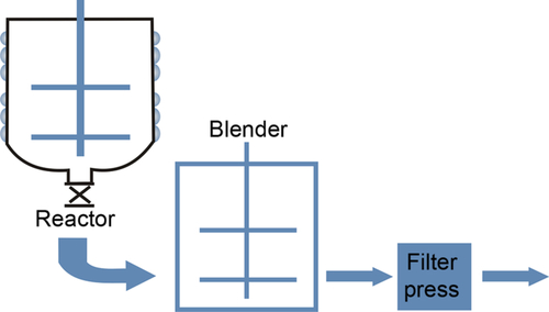
These routes are

OHM: Overhead mixer
SM: Sand mill
HSM: High-speed mixer
This route contains the following tasks:
■ Grinding
■ Thinning and tinting
■ Quality assurance
■ Packing
(A) Paints and coatings having extremely hard pigments are made by this route because they cannot be dispersed or grinned in TSD/sand mill.
(B) In this route, the task of TSD and OHM is accomplished by HSM. This route is preferred in pilot plants wherein the finished paint or coating for evaluation is required in extremely less quantity.
Thinning and tinting are the key tasks in pilot plant production of modern paints and coatings. Tinters belong to a group of additives. Tinters are mainly used for getting the required shades of the paint batches as per the market need. Following are the routes that are used while preparing the tinters:
TSD → OHM → SM → TINTERMIXER
BALL MILL → TINTERMIXER
HSM → SM → TINTERMIXER
9.5 Pilot Plants
Pilot plant is defined as a small version of a planned industrial plant, built to gain experience in operating the final plant. It is a small-scale industrial plant in which problems can be identified and solved before the full-scale plant is built. Pilot plant is often referred to as an experimental industrial plant in which processes or techniques planned for use in full-scale operation are tested in advance. A pilot plant allows investigation of a product and process on an intermediate scale before a large amount of money is committed to full-scale production.
In general, a pilot plant can be used for the following:
(a) Making product and process corrections based on evaluation results obtained for laboratory studies and their optimization and validation prior to scale-up
(b) Development of prototype new recipes and formulations
(c) Acquiring data to justify whether to go for full-scale production and, if found positive, designing and constructing a full-size plant or modifying an existing plant
(d) Development of alternate and cheaper sources of raw materials
(e) Generation of thermochemical data and reaction trends
(f) Evaluation of performance of critical raw materials/chemicals/additives
(g) Customer complaint investigation
9.5.1 Step by step scaling up
9.5.1.1 Reactors
Bench scale and lab scale systems are vital early-stage tools for assessing and scaling up new technology. Such systems are highly automated and customized for the application and are treated as a precursor to larger pilot and demonstration scale plants. Typical size of bench/lab reactor varies from 1 to 5 L.
For successful production of any product on a mega scale, pilot plant is a necessary tool to study the process involved. It also gives us a complete idea of the parameters that are of vital importance in getting a maximum yield and a product of high quality. Pilot plants provide the first window of the process development world. Performance/application tests are carried out to determine, or confirm, yield and other relevant data under a variety of operating conditions. Reactor size at the pilot plant scale typically ranges from 10 to 100 L.
Demonstration plants differ from pilot plants as the equipment and process flow sheet resemble much more closely to commercial scale operations. Demonstration plants can have significantly higher capital and operating costs than a pilot plant and are typically only employed when the process technology itself is already quite well developed. Reactor volumes typically fall within the 100-1000 L range.
9.5.1.2 General steps involved in scale-up
(a) The product economics are to be defined based on projected market size and competitive selling.
(b) Laboratory experiments and scale-up planning are conducted simultaneously.
(c) Critical monitoring parameters are defined in the proposed process.
(d) A pilot plant is constructed considering SHE requirements, cleaning and sanitizing systems, packaging, and waste handling systems.
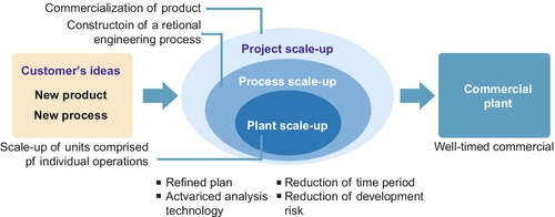
(e) The product and the process results of pilot plants are evaluated, including process economics to make any corrections, and a decision on whether to switch to a full-scale plant are taken. Figure 9.2 exhibits conceptual business modeling of a new product development.
Another frequently used word in scale-up is kilo lab, but it differs from pilot plant as shown in Table 9.1.

9.5.2 Pilot plant layouts—major issues
Pilot plants not only are necessary for process parameters and product quality point of view, but should be easy to approach. They should also have ease of operation and maintenance. Safety and disposal of toxic raw materials/by-products should also be given due importance in terms of usage and disposal while designing and commissioning. The critical parameters to be taken into account while designing and installation of pilot plant are depicted in Figure 9.3.

9.5.3 Process equipment and its support units
Table 9.2 shows the list of vital support units required for the process equipment used in a pilot plant for paints and coatings.
Table 9.2
Equipment Used in a Pilot Plant for Paints and Coatings
| Process Units | Support Units |
| Reactors—pressure and nonpressure | Suitable PCS/DCS control unit |
| Mixing vessels | Temperature control module |
| Pumps | Suitable heating/cooling system |
| Scales | A suitable and easily accessible control room |
| Ball mill—mixer | Air compressor |
| TSD: Sand mill—mixer | Suitable safety health and environment-related devices |
| HSM: Dyno mill—mixer | |
| Attritor—mixer | |
| Direct mixer | |
| JPT |
The basic requirement for pilot plants of paint and coating is to generate data for proper scale-up. A main criterion for processing is proper dispersion using suitable binders, which are essentially water-based or solvent-based polymers. Polymeric binders in use for paints and coatings include waterborne acrylic, styrene-acrylic emulsions, SBR, XSBR, NBR, XNBR emulsions, and solvent-based alkyd resins.
9.5.4 Types of pilot plant for water and solvent-based polymeric binders
The pilot plants for modern paints and coatings can be broadly classified as aqueous emulsion based pilot plant and solvent-based resin pilot plants.
9.5.4.1 Aqueous emulsion based pilot plant
These emulsions are the product of radical polymerization of unsaturated monomers in an aqueous medium. Their vital applications include binders for paints and plasters, paper and packing materials adhesives for wood, and binders and laminating materials for paper, textile, and leather processing. Such a polymerization is preferred to solution polymerization because of processing without organic solvents, shorter batch times, and constant product viscosities regardless of the rate of polymerization. The main components involved in this pilot plant are:
(a) Monomers: Major used monomers are vinyl propionate, vinyl acetate, butadiene, styrene, and acrylic and methacrylic derivatives. In order to achieve the desired finished product properties, a blend of monomers is used.
(b) Emulsion stabilizers: Surface active agents are required for stabilization of polymer particles during the formation of micelles during polymerization. It is observed that the emulsion produced with protective colloids could exhibit higher viscosities and large particle diameter compared to the polymers generated using just emulsifiers.
(c) Emulsifiers: In general anion-active and nonionic emulsifiers such as alkyl sulfates and -sulfonates, alkylethersulfates and -phosphates, sulfosuccinates, and ethoxylated fatty alcohols or nonylphenols are frequently used. The stabilizers for such emulsifiers are water soluble, high molecular organic compounds such as polyvinyl alcohol, hydroxyl ethyl cellulose, and polyvinylpyrrolidone.
(d) Initiators: The polymerization process requires water-soluble initiators such as ammonium or potassium peroxidisulfate and, less frequently employed, hydrogen peroxide.
(e) Buffers: During the polymerization process pH-value of the reaction mixture affects the saponification rates of some monomers (vinylic and acrylic esters) and, therefore, requires the presence of small quantities of buffers such as phosphates, carbonates, acetates, or borates.
(f) Water: Fully demineralized water is preferred because the presence of electrolytes in the process water has an adverse effect on the polymerization process. The qualities of water also affect the diffusion of monomer molecules partly through the water phase into the micelles of the emulsifier and formation of initiator radicals.
The batch emulsion polymerization is executed either by the monomer feed or the emulsion feed process.
Monomer Feed Process: In this process, an initial quantity of monomers, initiators, emulsifiers, or protective colloids and part of total water are fed into reactor. After attaining the desired temperature (generally 45-80 °C), the remaining quantity of monomers and other ingredients are charged at controlled rates.
Emulsion Feed Process: In this process a preemulsion is prepared from monomers, water, emulsifier, and initiator. A part of the preemulsion is transferred to the reactor and heated to up to desired temperature. The balance of the preemulsion is then added at a preset flow rate when the reaction has initiated. In Figure 9.4 various feeding modes such as continuous, semicontinuous, and direct dosing are schematically shown.

As another option, a part of the process water along with emulsifier and additives are charged to the reactor and finally adding a part of the preemulsion. After initiating the polymerization reaction, the remainder of the preemulsion is fed to the reactor at a preset rate. After the completion of the reaction, further initiator is added and the batch is maintained at reaction temperature to reduce the residual content of free monomers. Finally the batch is cooled and transferred to a cooling and mixing tank where auxiliary materials, such as plasticizers, defoaming agents, microbicides, and, if required, neutralizing agents, are added, and the batch is adjusted to the final product specification.
The main advantage of this process is that heat generated during the polymerization can be controlled by the cooling water circulation in the limpet coil of the reactor. Even the employment of an agitator with a drive designed for infinitely variable shaft speeds, an efficient blending, and heat removal at low shear forces are achieved.
A polymer emulsion pilot plant consists mainly of the following equipment:
(a) Charge equipment for raw materials with load cells for emulsifier tank, monomer blending tank, initiator and accelerator tanks and reactor, and automatic charge valves
(b) Emulsifier manufacturing equipment with tank, agitator, and transfer pump
(c) Monomer blending and feeding equipment with monomer blending tank, and initiator and accelerator tanks, each equipped with agitator, transfer pump, and flow meter
(d) Reaction equipment with reactor, reactor agitator, and distillation system. Butadiene-based emulsions require pilot plant with mechanical seal and appropriate safety equipment such as rupture disc
(e) Vacuum equipment with vacuum pump
(f) Heating and cooling circuit (primary and secondary) with circulation pump, heat exchanger,and control valves
(g) Cooling and blending equipment having cooling and blending tank and agitator
(h) Filter equipment with product pump and product filter
(i) Process control equipment and instrumentation with personal computer and software controllers, switch and control boards for the installation of the load equipment, and PLC
State of the art pilot plant for polymer emulsion includes high agitation efficiency, low shear rates, and excellent heat transfer using highly polished reactor and reactor agitator surfaces in contact with the product to facilitate cleaning operations. New technologies come with fully automatic process control through a personal computer with specifically developed user friendly software for a comfortable plant manipulation, optimum process operation, and reproducible product characteristics. A pilot plant for taking up development work for a butadiene (gaseous monomer) recipe such as styrene butadiene and acrylonitrile butadiene rubbers is shown in Figure 9.5.

9.5.4.2 Solvent-based resin pilot plants
Resins are the condensation/addition polymers that are formed by reacting monomer functional groups. It is the film-forming material and provides gloss and adhesion to paint and coating. These binders are also used to bind the pigment and extender to the substrate.
Resin plays a vital role in overall paint formulation, such as:
i. It converts liquid coating into solid film after application as a thin film by air-drying or drying mechanism.
ii. It provides gloss to finished paint and coating films.
iii. It provides flexibility and hardness to the paint film.
iv. It facilitates paint and coating adherence to the surface.
v. It imparts resistance to water, alkali, and abrasion.
vi. It helps in the easier dispersion of pigment and extender in a uniform way on the substrate.
Different types of binders used in the modern paints and coating industries are alkyd resin, nitrocellulose, amino resin, polyesters, phenolics, chlorinated rubber, acrylic resin, epoxy resin, silicone resin, and polyurethane.
Resin pilot plant includes substantial equipment like pilot reactor, blender, and filter machine. The pilot plant contains accessories such as nitrogen gas line with rota meter, temperature and pressure indicators, sampling port, condenser, separator with auto siphon pot, and vacuum pump. Normal utilities required are heating media, cooling tower, compressor, chilling plant, nitrogen and instrument air, and so on. During resin processing, few important physical and chemical properties are monitored in pilot plants, for example, color, clarity, viscosity, acid value, % nonvolatiles (120 °C/1 h), hydroxyl value, finish on Hegmann gauge, weight per liter, dilution viscosity, and drying characteristics. Process control in resin pilot plants includes measurement of water of reaction, stirring speed (RPM) and type of agitator, addition time of ingredients, reaction time, temperature, steam pressure, and so on.
9.6 Major Equipment Used in Paints and Coating Industry
Mixers, mills, and filters are the major equipment used in production of paints and coatings. It is, therefore, necessary that pilot plants for paints and coatings must contain small replicas of the above equipment for effective and accurate data for scale-up. However, the principle remains the same, only the size differs. Figure 9.6 shows a schematic diagram of reactor and accessories required for polymeric binders.
9.6.1 Mixers
Mixers are used to achieve homogeneity between different components of paints and coatings. Mixers are used in the following operations:
■ Decreasing the viscosity of resins and varnishes
■ Mixing pigments and fillers with coating materials
■ Mixing additives with paints or varnishes
■ Adding solvents or diluting agents (thinner) to paints to adjust the viscosity
■ Preparing emulsion (water-based) paints
There are several types of mixers used in the paint and coating industry depending upon their suitability for different end applications. Choice of mixer type depends on viscosity, density difference between components, and solid particle size.
There are different types of mixers:
■ Automatic mixers
■ Kneaders
■ Colloid mills
■ Rotary churns
■ Mixing by air streams
VisiMix—an engineering modeling tool that simulates mixing and heat transfer in stirred tanks was used by Solutia in product and process development. This tool was successfully used to assess the mixing and heat transfer capability of a pilot reactor for a new resin product. It was also exceptionally useful to design pilot plant agitation configuration for a new process and to scale-up a lab reactor to a pilot vessel to match the particle size distribution of the final product.2
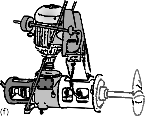
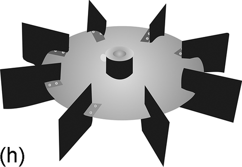
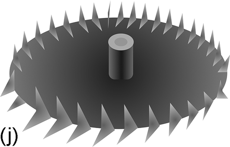
Figure 9.7a–q3 shows impellers and mixers useful in both pilot plants of modern paints and the coating industry.

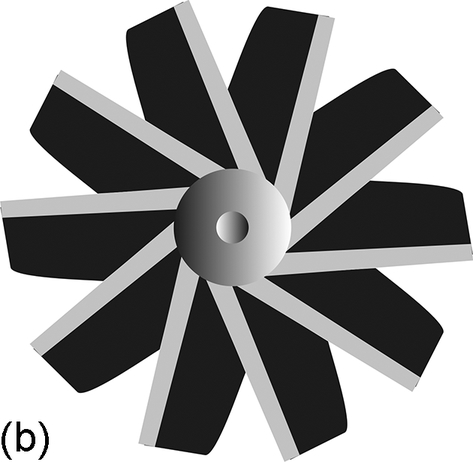
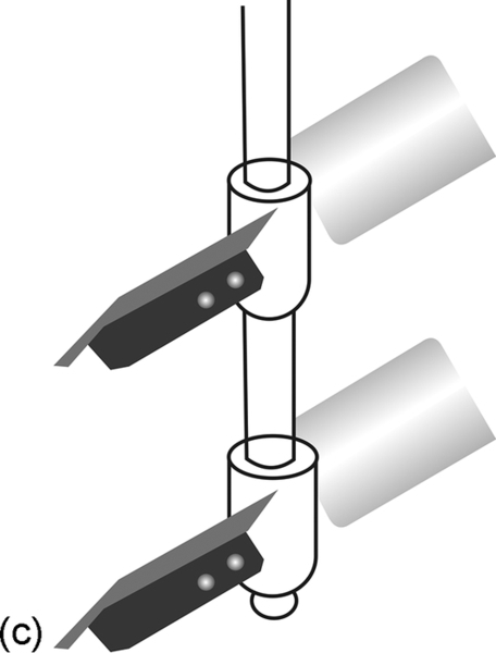


The mixers usually consist of the mixing tank, usually vertical, and one or more impeller(s) driven by an electrical motor; the mixing tank may also have vertical baffles. The impeller consists of a shaft assembled with one or more mixing blades propellers. Propellers can be divided into two main types, axial and radial flow propellers.
Axial flow propellers as shown in Figure 9.7a–f is considered the most commonly used in paints and coating industry. The impeller in Figure 9.7d is fixed in the wall of the mixing tank with suitable inclination; it can be also fixed vertically at the axis of mixing tank using vertical baffles. These impellers rotate at speeds between 1150 and 1750 rpm. The vertical type as shown in Figure 9.7e is used in preparing colloids and rotates at speeds between 350 and 420 rpm via gearbox. The inclined high-speed type is used for the preparation of various kinds of emulsions. The type shown in Figure 9.7f is used to mix liquids that are free from solid particles.
Radial flow propellers as shown in Figure 9.7g–j have blades parallel to the propeller shaft axis. On the other hand, turbine propellers as shown in Figure 9.7g–h rotate the mixing tank contents in a circular motion in both vertical and axial directions. The diameter of paddle propellers shown in Figure 9.7i reaches 60% of the mixing tank diameter and rotates with relatively low speeds.
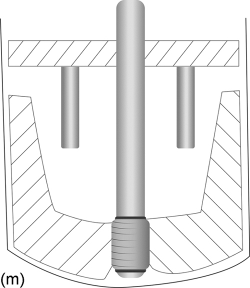
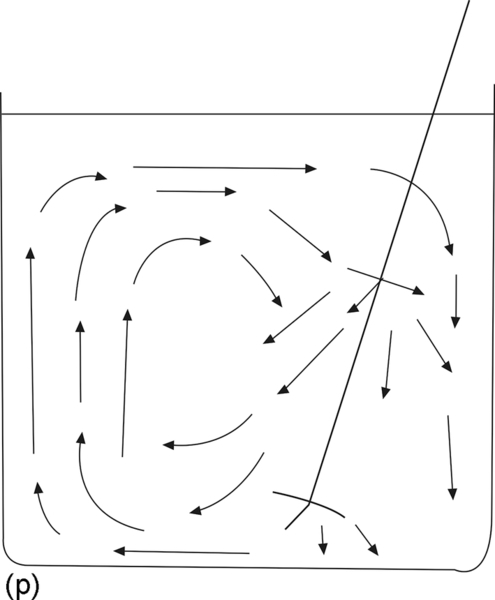
Paddle stirrers are used in mixing high viscosity liquids or pastes, whereas anchor stirrers are used for extremely high viscosity liquids or pastes, as shown in Figure 9.7k–m. This type has a small clearance between the mixing propeller and mixing tank walls. Figure 9.7n shows the multiple vane stirrers, and Figure 9.7o–p3 shows the motion of the inclined propellers.
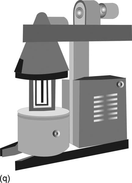
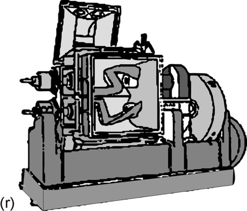
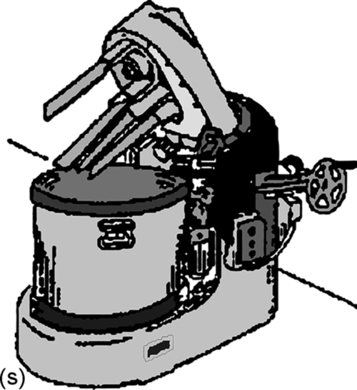
Figure 9.7q3 shows typical kneaders used in the production of putties. The kneader consists of a separate tank that can be fixed in the mixer or transferred with its contents to the packing unit. This system helps in weighing the tank content before mixing and to clean the mixing vessel in the cleaning unit. In this system, the mixers can be elevated vertically or laterally as shown in Figure 9.7r.3
A horizontal kneader composed of a U-shaped vessel in two mixers with unique shape rotate in different directions with small clearance between them, as shown in Figure 9.7s.3 There are other types of kneaders including one that can be heated by steam or cooled by water in order to control the viscosity of the mixture.
A few essential types of mixers are described below:
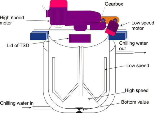
(a) Twin Shaft Disperser (TSD): It is mild steel-made processing vessel fitted with two shafts at the top. The central shaft is referred to as the slow speed shaft and is connected to a cage having scrappers and is rotated at the rpm of about 30 to 40. It is designed to scrape the mill base material, which is stuck to the inner wall of the vessel during the mixing process. The other shaft, which is fitted at an inclination to the central axis, the cylindrical vessel, rotates at an exceedingly high speed of about 1400 rpm. This shaft is fitted with a circular saw-blade type impeller disc at the bottom that is known as a cowl disc. The saw-blade type impeller is designed and placed inside the vessel in such a manner that the mixture of powder, medium, and the solvent is subjected to proper shear flow patterns in order to achieve the dispersion.
(b) Overhead Mixture (OHM): The main task of this machine is to grind the batch that comes from TSD. Normally this machine is fitted just next to TSD.
(c) High-Speed Disperser (HSM): This equipment is used when the pigment is lesser in compared to the solvent to achieve homogenous dispersion.
9.6.2 Mills
The paint and coating industry uses different types of mills, such as roller mills and ball mills. A three-roller mill is shown in Figure 9.8,3 in which each roller rotates in the opposite direction of others and with different speeds with a 1:3:9 ratio. The clearance between each two rollers is the key factor to maintain the desired finesse of dyes that leads to the desired homogeneity. This type of mills is open and, therefore, cannot be used in grinding of paints that contain high volatility solvents because emissions may lead to SHE-related issues.

Another relevant class is the ball mills. This type consists of a cylinder rotating about its horizontal axis and containing the grinding balls that may be made of steel or pebbles. If steel balls are used, the cylinder lining will be also made of steel and is used only with dark color paints and coatings. But if the balls are made of pebbles or ceramics the cylinder lining will be made of ceramic or silica and can be used with white or light color. The grinding efficiency and fineness of particles are dependent on the dimensions of the cylinder, speed of rotation, balls size, and balls density. Some mills have the length of the cylinder equal to its diameter, but to maintain a higher degree of fineness mills with a length larger than their diameter are used. Other types of mills include one in which the grinding operation is made in steps inside the mill as the cylinder is separated into sections with screens with suitable sizes separating the sections wherein the initial grinding is done in the first section and the finishing is done in the final section. A bars mill is used instead of balls in order to obtain particles with slightly different sizes that are suitable for dry grinding and/or grinding of colloidal particles.
Presently, the most commonly used mills, in large modern factories, are sand mills (vertical or horizontal) and dyno mills. The relations between the internal diameter of balls mills and the diameter of balls are shown in Table 9.33 and Figure 9.9.3
Table 9.3
Relations Between the Internal Diameter of Ball Mills and the Ball Diameter
| Internal Diameter | Ball Diameter (cm) and Their Percentage |
| 30-60 | 1.5 (70%), 2.5 (30%) |
| 90-120 | 1.5 (30%), 2.5-4 (60%), 4-5 (10%) |
| 120-150 | 2-2.5 (85%), 5-6.5 (15%) |

CVRD’s research center has conducted pilot tests to discover new technologies of improving ball milling efficiency on grinding mill feed. It was noticed that with a mill feed having particle finesse below 170 μm, millpebs when mixed at 30% by weight with grinding balls improves ball milling efficiency by 15%. The results of pilot plant trials proved that millpebs breakage rate exceeds that for 25 mm grinding balls from 209 to 44 μm; however, performance is similar below 44 μm. Somehow, at 80% slurry density, millpebs were escaping the mill.4
Some of the primarily used mills are described below:
(a) Sand Mill (SM)
The sand mill is equipment used for size reduction of powder particles uniformly dispersed in the premixed millbase. The premixed millbase is passed through a cylinder bank of sand, which is being subjected to intense agitation. During passage upward through the agitated sand zone, the millbase is caught and ground between the sand particles—a strong shearing action that affects the dispersion of the pigment into the vehicle and also reduces the particle size of the pigment. On emerging from the active sand zone, the dispersed millbase overflows through an exit screen having size enough to permit free flow of the millbase while holding the sand particles.
The agitation of the sand particles is produced by flat disk impellers, which revolve at extremely high speed (peripheral velocity of 2000 ft/min) inside the shell of the sand mill. Sand particles and millbase adjacent to the impeller surfaces pick up the impeller motion through viscous resistance and, as a result, are slung outward against the confining walls of the shell. The shell is fitted with a jacket to allow cooling water circulation in order to dissipate the heat generated during the grinding process. The critical process parameter in this process is the flow rate of millbase coming out of the sand mill. This is crucial for achieving the desired dispersion and grinding. Generally the grinding media used are glass beads of size 0.6 to 1.4 mm. And the amount of grinding media filled in the shell of the sand mill is about half of the shell volume.
(b) Ball Mill
This equipment is mostly used for paints and coatings consisting of extremely hard pigments. Unlike the sand mill route, both premixing and grinding operation are carried out in single equipment.
A ball mill consists of a cylinder container mounted horizontally and partially filled with either pebbles or ceramic or metallic balls, known as grinding media. The entire quantity of powders (pigments and extenders), part of the medium and solvent, along with dispersing agents are charged to the ball mill. Grinding (dispersion) of the millbase is accomplished by rotating the ball mill and its constituents about the horizontal axis of the mill at a rate sufficient to lift the pebbles or balls to one side and then cause them to roll, slide, and tumble to the lower side. Because of this cascading action pigment particles are caught between the tumbling balls and are subjected to both impact and intensive shear. This highly turbulent mixing action on the millbase trapped in the ball interstices imparts the required dispersion effect. Some of the decisive factors that need to be monitored for achieving effective dispersion are:
■ Speed of rotating of the ball mill
■ Ball charge
■ Millbase viscosity
(c) Attritor
An attritor is similar to the ball mill in operation. The only difference between an attritor and a ball mill is that the ball mill rotates around a horizontal axis whereas the attritor rotates vertically.
9.6.3 Filters
During the manufacturing in paints and coatings industry or during the oil heating process the liquids are contaminated by foreign matters. Moreover, the paint and coating may contain particles that were not properly ground or some polymers that remain undissolved. Some surface hardness may also contribute to the contamination. Figure 9.105 shows a type of filter.

For all such reasons, paints and coatings in liquid form must be purified by either of the following methods:
■ Using filter press
■ Using centrifugal separator
■ Using fine screens
■ Using settling techniques
Centrifuges, screens, or pressure filters are used to remove nondispersed pigments. The finished paint or coating produced from pilot plant is poured into small can, labeled, packed, and moved to storage area/shelf.
9.7 General Checkpoints for a Paint and Coating Pilot Plant
For the smooth start-up of a pilot plant for paints and coatings, there are certain routine checks that should be carried out. Normally this covers cleanliness of reactor, and working of accessories including safety devices and process control systems. Table 9.4 shows typical checkpoints:
Table 9.4
Checkpoints for a Typical Paint and Coating Pilot Plant Manufacturing
| Reactor condition | Clean reactor/no residue/valve function/periodical testing of pressure/periodical testing of coil pressure/ultrasonic thickness measurement/periodical external inspection/testing of safety devices |
| Separator | Drain line ok/view glass clear |
| Condenser | Vent open cooling pressure ok |
| Cooling tower | Proper pressure standby the pump in operating condition |
| Nitrogen pressure | Inert atmosphere, reflux rate |
9.8 General Safety Precautions in Paint and Coating Pilot Plant
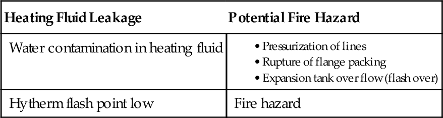
Because most of the ingredients in the trials are volatile and explosive, it is of utmost importance to augment pilot plant with suitable and proper safety devices such as safety valves and rupture discs. Listed in Table 9.5 are some common safety checkpoints that are normally taken care of prior to charging in the pilot reactors.
9.9 Typical Example of Pilot Scale Trial and Scale-Up of Acrylic Latex for Coating Applications
Tables 9.6 and 9.7 show a typical recipe for latex used in coating applications; processing parameters; a temperature profile; and typical finished latex properties.
Table 9.6
Typical Recipe of Styrene Butylacrylate Latex for Coating Application
| Ingredient | Recipe Parts Boma |
| Initial aqueous charge | |
| Process water | 61.5 |
| Anionic emulsifier | 0.17 |
| Feed into reactor | |
| Monomer mixture | |
| Butylacrylate | 85.0 |
| Methylmethacrylate | 13.0 |
| Methacrylic acid | 2.0 |
| Surfactant solution | |
| Anionic emulsifier | 1.35 |
| Process water | 20.0 |
| Catalyst solution | |
| Process water | 25.0 |
| Potassium persulfate | 0.45 |

a Bill of material.
Table 9.7
Typical Properties of the Latex (Before pH Make-Up)
| Parameters | Value |
| Total solids | 47.5% |
| pH | 2.5 |
| Conversion | 99.7% |
| Grit content | Nil |
| Particle size | 1000 A° |
| Brookfield viscosity RV # 50, rpm @25 °C | 45 cps |
| Surface tension @25 °C | 45 dynes/cm |
| Mechanical stability | Medium |
9.9.1 General process of charging
■ Charge the initial aqueous charge in the reactor.
■ Raise the temperature of reactor to 80 °C with nitrogen purging. Nitrogen blanketing should be maintained throughout the reaction.
■ Charge 10% of monomer mixture and surfactant solution and 20% catalyst solution within 10 min into the reactor. Hold all the feeds for 15 min at this stage.
■ Thereafter feed the remaining parts of monomer mixture, surfactant solution, and catalyst solution with controlled feed rate in 4 h. Maintain the temperature at 80 °C throughout the run.
■ After addition of all the feeds is complete, hold the reactor at 80 °C for 30 min.
■ Cool the reactor to 30 °C or to ambient temperature and adjust the pH of finished latex to 7.0 using ammonia.
9.9.2 Pilot plant setup
In general, pilot plant of aqueous emulsion R&D consists of a reactor, facility for nitrogen blanketing, intermediate vessels for making different solutions, agitators, jacket for circulating temperature maintaining fluid, flow meters to maintain desired flow rate, and so on. Last but not least it should have a proper safety device such as a safety valve and rupture disc. For precise control it normally should have a sophisticated control system to maintain temperature profile and automatic charging of ingredients in a stipulated time period. Series of experiments are conducted in the pilot reactor to optimize recipe that is screened initially on a lab reactor, and subsequently in a similar way the recipe is further optimized with respect to thermochemical data and finished product quality.
For further scale-up to the commercial production, the following engineering calculations as shown in Tables 9.8–9.10 are of utmost significance to get the desired finished product with targeted properties and quality in line with what was obtained at pilot scale.
Table 9.8
Geometric Proportions for a Standard Agitation System
| DA:DT = 1:3 | H:DT = 1 | J:DT = 1:12 |
| E:DA = 1 | W:DA = 1:5 | L:DA = 1:4 |
| B = Number of blades on impeller R = Number of baffles DA = Agitator diameter H = Liquid height DT = Tank diameter E = Height of the agitator from the bottom of the tank L = Baffle width J = Agitator blade length W = Agitator blade width | ||
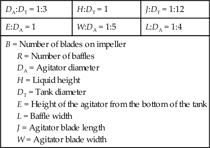
Table 9.9
Impeller Selection Guide
| Type of Impeller | Range of Liquid (cP) | Viscosity (kg/m s) |
| Anchor | 102-2 × 10³ | 10- 1-2 |
| Propeller | 100-104 | 10- 3-101 |
| Flat-blade turbine | 100-3 × 10⁴ | 10- 3-3 × 101 |
| Paddle | 102-3 × 101 | 10- 1-2 × 101 |
| Gate | 103-105 | 100-102 |
| Helical screw | 3 × 10³-3 × 10⁵ | 3-3 × 10² |
| Helical Ribbon | 104-2 × 10⁶ | 101-2 × 10³ |
| Extruders | > 106 | > 103 |
Table 9.10
Important Engineering Parameters for Mixing6
NRe = 10.75Nd2S/μ, Reynolds number
Np = 1.523(1013)P/N3d5S, Power number
NQ = l.037(105)Q/Nd3, Flow number
tbN = Dimensionless blend time
NFr = 7.454(10- 4) N2d, Froude number
d = impeller diameter (in.)
D = vessel diameter (in.)
N = rpm of impeller shaft
P = horsepower input
Q = volumetric pumping rate (cuft/s)
S = specific gravity
tb = blend time (min)
p = viscosity (cP)
9.10 Conclusion
Pilot plants still play a key role in the modern paints and coating industry and give firsthand information about processing parameters, product quality, and any associated safety, health, and environment-related aspects. This especially helps create a timely and hassle-free scale-up of the desired paint and coating and one that is of high and consistent quality. Pilot plants play major roles in FMCG products such as paints and coatings, where entering into the market and reaching the masses and meeting customer satisfaction is the topmost priority.