

Software implementation
This chapter describes how to implement the IBM Virtualization Engine TS7700 on the IBM System z host systems. The tasks you must complete include defining the hardware to the hosts by using the hardware configuration definition (HCD) menus and other operating system-specific tasks.
From a software perspective, differences exist between the IBM Virtualization Engine TS7740 and the IBM Virtualization Engine TS7720. If no specific differences are indicated, the implementation steps apply to both. Otherwise, the differences are explained in each relevant step.
In a z/OS environment, Data Facility Storage Management Subsystem (DFSMS) provides automated system management of tape libraries. In addition to the implementation steps described in this chapter, you can find a step-by-step implementation process in Appendix B, “IBM Virtualization Engine TS7700 implementation steps” on page 861 and Appendix E, “Case study for logical partitioning of a two-cluster grid” on page 905.
This chapter includes the following sections:
6.1 Host implementation considerations
From a host perspective, each TS7700 Virtualization Engine supports 16 tape CUs, each with 16 IBM 3490E tape drives, for a total of 256 tape drives. With the release of TS7700 Virtualization Engine R2.0, up to a six-cluster grid can be configured, which provides the capability for 96 tape CUs, with a total of 1536 tape drives. Each TS7700 Virtualization Engine can be host-attached through two or four FICON channels.
The host does not know whether it is dealing with “physical” 3490E tape drives or with the virtual 3490E tape drives of the TS7700 Virtualization Engine. Therefore, the TS7700 Virtualization Engine with virtual 3490E tape drives is defined just like physical IBM 3490-C2A controllers with 16 addresses through the hardware configuration definition (HCD) interface.
Before you can use the TS7700 Virtualization Engine, you need to define it to the System z host through HCD. Because the virtual tape drives of the TS7700 Virtualization Engine are library resident, you must specify LIBRARY=YES in the define device parameters. If Fibre Channel connection (FICON) directors are being installed for the first time, the directors themselves can also be defined in the input/output configuration program (IOCP) and HCD input/output definition file (IODF).
In a z/OS environment, you define the composite and distributed libraries to storage management subsystem (SMS) and then update the SMS constructs and automatic class selection (ACS) routines to direct mounts to the TS7700 Virtualization Engine. See 6.3, “TS7700 Virtualization Engine software definitions for z/OS” on page 308 for more details about the implementation in a System z environment. You might need to update Missing Interrupt Handler (MIH) values also, as described in 6.2.6, “Set values for the Missing Interrupt Handler” on page 306.
The software implementation steps for z/VM and z/VSE are described in 6.6, “Software implementation in z/VM and z/VSE” on page 316. For Transaction Processing Facility (TPF)-related implementation details, see 6.7, “Software implementation in Transaction Processing Facility” on page 323.
After defining the TS7700 Virtualization Engine to a system, verify that the devices can be brought online. Plan to update the expected IPL configuration and validate that an IPL does not generate production problems with the changed definitions.
Authorized program analysis reports (APARs) have been created that address the use of multicluster grids. Search for the newest D/T3957 preventive service planning (PSP) buckets before you install new clusters. A recent APAR that addresses software handling for multiple distributed libraries is OA33450.
6.1.1 Sharing the TS7700 Virtualization Engine by multiple hosts
Each multicluster grid or stand-alone grid has its own library sequence number, which is used to define the logical library to the host. Each logical library identified as a composite library looks like a separate library to the host. A TS7700 Virtualization Engine can be shared by multiple System z systems, VM, VSE, and TPF systems.
Sharing can be achieved in two ways:
•By logically dividing the TS7700 Virtualization Engine into separate partitions (partitioning)
•By allowing all attached systems to sequentially access all physical and logical volumes (sharing)
Sharing of an IBM Automated Tape Library means that all attached hosts have the same access to all volumes in the tape library. To achieve this sharing, you need to share the host control data sets, that is, the tape management system inventory, the integrated catalog facility (ICF) catalog information, and the write to operator with reply, among the attached hosts. In a non-SMS environment, all systems must share the ICF catalog that contains the Basic Tape Library Support (BTLS) inventory.
In general, these requirements can be met only in a single-platform environment. In this configuration, only one global tape volume scratch pool per media type is available.
6.1.2 Partitioning the TS7700 Virtualization Engine between multiple hosts
Partitioning is the solution if you need to dedicate the use of volume ranges to certain systems or complexes, or separate host platforms. Dividing one or more libraries into logical libraries is the easiest way to allow different hosts to access them. Each host or complex owns its own set of drives and volumes, which another system or complex cannot access without manual intervention. Each system knows only about its part of the library. Partitioning is also appropriate for the attachment to a z/OS logical partition (LPAR) for testing.
This partition is implemented through values updated in the DEVSUPxx category definitions. Up to now, to modify a category value, you needed to change the DEVSUPxx member and IPL the system. A new command, DS QLIB, CATS, allows you to query and modify these category values without IPL; however, this must be done with great care as a discrepancy in this area will cause scratch mounts to fail. See 6.2.5, “Display and control your settings” on page 302 for further information.
With the introduction of the Selective Device Access Control (SDAC) function, the partitioning possibilities for the TS700 have been improved. See more about SDAC in 6.4, “Implementing Selective Device Access Control” on page 311. A step-by-step description of partitioning is located in Appendix E, “Case study for logical partitioning of a two-cluster grid” on page 905.
6.1.3 Logical path considerations
The TS7700 Virtualization Engine attaches to the host system or systems through two or four FICON adapters. Each FICON channel connected to the FICON adapter provides support for 256 logical paths. A four FICON configuration will result in a total of 1,024 logical paths per TS7700 Virtualization Engine.
To calculate the number of logical paths required in an installation, use the following formula:
Number of logical paths per FICON channel = number of LPARs x number of CU
This formula assumes that all LPARs access all control units (CUs) in the TS7700 Virtualization Engine with all channel paths.
For example, if one logical partition (LPAR) has 16 CUs defined, it means that you are using 16 logical paths of the 256 logical paths available on each FICON adapter. See Table 6-1 for the number of logical paths that are used in various scenarios.
Table 6-1 Logical paths per FICON channel
|
Number of CUs defined
|
Number of LPARs
|
Logical paths used
|
Maximum paths
|
|
16
|
8
|
128
|
256
|
|
16
|
16
|
256
|
256
|
|
8
|
32
|
256
|
256
|
The FICON Planning and Implementation Guide, SG24-6497, covers the planning and implementation of FICON channels and operating in FICON native (Fibre Channel (FC)) mode. It also discusses the FICON and FC architectures, terminology, and supported topologies.
Define one tape CU in the HCD dialog for every 16 virtual devices. Up to eight channel paths can be defined to each CU. A logical path might be thought of as a three-element entity: A host port, a TS7700 Virtualization Engine port, and a logical CU in the TS7700 Virtualization Engine.
|
Remember: A reduction in the number of physical paths will reduce the throughput capability of the TS7700 Virtualization Engine and the number of available logical paths. A reduction in CUs will reduce the number of virtual devices available for any individual host.
|
6.1.4 Library names, Library IDs, and port IDs
Library names, Library IDs, and port IDs are used to define the TS7700 Virtualization Engine to the host at the hardware, operating system, and SMS level. Some of these identifiers are also used by the IBM System Services Representative (SSR) in the hardware configuration phase of installation.
On the host side, this means that definitions must be made in HCD and in the SMS. See Table 6-2 for an example, and create a similar one during your planning phase. It will be used in later steps. The Library ID must only contain hexadecimal characters (0-9 and A-F).
Table 6-2 lists examples of the library names and IDs needed in a z/OS implementation.
Table 6-2 Sample of library names and IDs: Four-cluster TS7700 Virtualization Engine implementation
|
TS7700 Virtualization Engine virtual library names
|
SMS name1
|
LIBRARY-ID
|
Defined in HCD
|
Defined in SMS
|
|
IBMC1 (Composite)
|
IBMC1
|
C7401
|
Yes
|
Yes
|
|
IBMD1TU (Distributed Tucson)
|
IBMD1TU
|
D1312
|
No
|
Yes
|
|
IBMD1PH (Distributed Phoenix)
|
IBMD1PH
|
D1307
|
No
|
Yes
|
|
IBMD1SJ (Distributed San Jose)
|
IBMD1SJ
|
D1300
|
No
|
Yes
|
|
IBMD1AT (Distributed Atlanta)
|
IBMD1AT
|
D1963
|
No
|
Yes
|
1 The SMS name cannot start with a “V”.
Distributed library name and composite library name
The distributed library name and the composite library name are defined to z/OS and DFSMS. The composite library name is linked to the composite library ID when defining the tape library to DFSMS, as shown in Figure 6-10 on page 309. In the same manner, the distributed library name is linked to the distributed library ID, as shown in Figure 6-11 on page 310. Use names that are similar to those listed in Table 6-2 on page 288. Use the letter “C” to indicate the composite library names and the letter “D” to indicate the distributed library names. The composite library name and the distributed library name cannot start with the letter “V”.
The distributed library name and the composite library name are not directly tied to the configuration parameters used by the IBM SSR during the installation of the TS7700 Virtualization Engine. These names are not defined to the TS7700 Virtualization Engine hardware. However, to make administration easier, it is useful to associate the LIBRARY-IDs with the SMS library names through the nickname setting in the TS7700 Virtualization Engine management interface (MI).
|
Remember: Match the distributed and composite library names entered at the host with the aliases defined at the TS7700 Virtualization Engine MI. Although they do not have to be the same, it will simplify the management of the subsystem.
|
LIBRARY-ID and LIBPORT-ID
LIBRARY-ID and LIBPORT-ID are z/OS HCD parameters that allow HCD to provide the composite library configuration information that is normally obtained by the operating system at IPL time. If the devices are unavailable during IPL, the HCD information allows the logical tape devices to be varied online (when they subsequently become available to the system) without reactivating the IODF.
|
Tip: Specify the LIBRARY-ID and LIBPORT-ID in your HCD/IOCP definitions, even in a stand-alone configuration. This reduces the likelihood of having to reactivate the IODF when the library is not available at IPL and providing enhanced error recovery in certain cases. It might also eliminate the need to IPL when you make changes to your I/O configuration. In a multicluster configuration, the LIBRARY-ID and LIBPORT-ID must be specified in HCD, as shown in Table 6-6 on page 299.
|
Distributed library ID
During installation planning, each cluster is assigned a unique, five-digit hexadecimal number, (that is, the sequence number). This is used during subsystem installation procedures by the IBM SSR. This is the distributed library ID. This sequence number is arbitrary, and can be selected by you. It can start with the letter D.
In addition to the letter D, you can use the last four digits of the hardware serial number if it only consists of hexadecimal characters. For each distributed library ID, it will be the last four digits of the TS7700 Virtualization Engine serial number.
If you are installing a new multicluster grid configuration, you might consider choosing LIBRARY-IDs that clearly identify the cluster and the grid. The following examples can be the distributed library IDs of a four-cluster grid configuration:
Cluster 0 DA01A
Cluster 1 DA01B
Cluster 2 DA01C
Cluster 3 DA01D
The composite library ID for this four-cluster grid can then be CA010.
|
Important: Whether you are using your own or IBM nomenclature, the important point is that the subsystem identification must be clear. Because the identifier that appears in all system messages is the SMS library name, it is important to distinguish the source of the message through the SMS library name.
The distributed library ID is not used in defining the configuration in HCD.
|
Composite library ID
The composite library ID is defined during installation planning and is arbitrary. The LIBRARY-ID is entered by the IBM SSR into the TS7700 Virtualization Engine configuration during hardware installation. All TS7700 Virtualization Engines participating in a grid will have the same composite library ID. In the example in “Distributed library ID”, the composite library id starts with a “C” for this five hex-character sequence number. The last four characters can be used to uniquely identify each composite library in a meaningful way. The sequence number must match the LIBRARY-ID used in the HCD library definitions and the LIBRARY-ID listed in the Interactive Storage Management Facility (ISMF) Tape Library definition windows.
|
Remember: In all configurations, each LIBRARY-ID, whether distributed or composite, must be unique.
|
LIBPORT-ID
The LIBPORT-ID reflects the order in which the tape CUs are configured to the TS7700 Virtualization Engine across all distributed libraries participating in a composite library.
DEVICE SERVICES QTAPE command
In an existing installation, you can use the DEVSERV QTAPE system command to discover what to specify. All tape drives (logical or physical) connected to a given logical control unit (LCU, CU) have the same LIBPORT-ID. Therefore, you only have to issue the DS QT command once per CU for any logical device number in that string of 16.
The command syntax is shown in Example 6-1.
Example 6-1 QTAPE command
DS QT,devnum,1,RDC
The values in the command are defined:
DS Device service
QT Query tape
devnum Device address
1 Number of devices to be displayed
RDC Read device characteristics
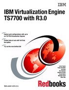
Figure 6-1 shows the output of a DS QT system command.
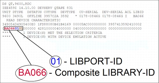
Figure 6-1 Sample DEVSERV QT command output
|
Clarification: The distributed library number or cluster index number for a given logical drive can be determined with the DS QT command. As identified in Figure 6-1, the response shows LIBPORT-ID 01 for logical drive 9600. LIBPORT-ID 01 is associated with Cluster 0. The association between distributed libraries and LIBPORT-IDs is discussed in 6.2.1, “Defining devices through HCD for Cluster 0” on page 292.
|
From the DS QT command in Figure 6-1, you can derive the LIBRARY-ID for the composite library and the LIBPORT-ID of the LCU presenting the logical device. The real device type of the physical devices is unknown to the host and DEVSERV always shows 3592 as DEVTYPE. The LIBID field identifies the composite library ID associated with the device.
|
Tip: You can get the real device type from the Host Console Request function LIBRARY REQUEST,<distributed library name>,PDRIVE located in the distributed library.
The short form of LIBRARY REQUEST is LI REQ.
|
6.2 Hardware configuration definition
This section describes the process of defining the TS7700 Virtualization Engine through the hardware configuration definition (HCD) interface for Cluster 0. The following points are the most important:
•HCD definitions are required.
•Up to sixteen 3490 tape CUs can be defined per TS7700 Virtualization Engine, with 16 x 3490E drives each.
•Keep the link address blank when no FICON director is used.
•Specify LIBRARY=YES when using system-managed tape.
Usually, HCD definitions are made by z/OS system administrators. A helpful approach is to fill in a table with all the definitions that the administrators need to be able to create HCD, and then give the table to the administrators. Table 6-3 is an example for Cluster 0. In general, all the blank cells must be filled in by system administrators because they know what channels are free, what CU numbers are free, and so on.
Table 6-3 HCD definitions table for Cluster 0
|
CHPID
|
CU
|
CUADD
|
Link
|
Devices
|
ADD
|
LIB-ID
|
Libport
|
|
|
|
0
|
|
|
00-0F
|
|
01
|
|
|
|
1
|
|
|
00-0F
|
|
02
|
|
|
|
2
|
|
|
00-0F
|
|
03
|
|
|
|
3
|
|
|
00-0F
|
|
04
|
|
|
|
4
|
|
|
00-0F
|
|
05
|
|
|
|
5
|
|
|
00-0F
|
|
06
|
|
|
|
6
|
|
|
00-0F
|
|
07
|
|
|
|
7
|
|
|
00-0F
|
|
08
|
|
|
|
8
|
|
|
00-0F
|
|
09
|
|
|
|
9
|
|
|
00-0F
|
|
0A
|
|
|
|
A
|
|
|
00-0F
|
|
0B
|
|
|
|
B
|
|
|
00-0F
|
|
0C
|
|
|
|
C
|
|
|
00-0F
|
|
0D
|
|
|
|
D
|
|
|
00-0F
|
|
0E
|
|
|
|
E
|
|
|
00-0F
|
|
0F
|
|
|
|
F
|
|
|
00-0F
|
|
10
|
6.2.1 Defining devices through HCD for Cluster 0
You can define up to 16 CUs with 16 devices each per cluster in the grid configuration. Use CUADD=0 through CUADD=7 and LIBPORT-IDs of 01 through 08 for the first eight CUs, as shown in Table 6-4.
Table 6-4 CUADD and LIBPORT-ID for the first set of 256 virtual devices
|
CU
|
1
|
2
|
3
|
4
|
5
|
6
|
7
|
8
|
|
CUADD
|
0
|
1
|
2
|
3
|
4
|
5
|
6
|
7
|
|
LIBPORT-ID
|
01
|
02
|
03
|
04
|
05
|
06
|
07
|
08
|
For the ninth to sixteenth CUs, use CUADD=8 through CUADD=F and LIBPORT-IDs of 09 through 10, as shown in Table 6-5.
Table 6-5 CUADD and LIBPORT-ID for the second set of virtual devices
|
CU
|
9
|
10
|
11
|
12
|
13
|
14
|
15
|
16
|
|
CUADD
|
8
|
9
|
A
|
B
|
C
|
D
|
E
|
F
|
|
LIBPORT-ID
|
09
|
0A
|
0B
|
0C
|
0D
|
0E
|
0F
|
10
|
Figure 6-2 and Figure 6-3 on page 294 show the two important windows for specifying a tape CU.
|
------------------------ Add Control Unit ---------------------
CBDPCU10 Specify or revise the following values. Control unit number . . . . 0440 + Control unit type . . . . . 3490 + Serial number . . . . . . . __________ Description . . . . . . . . ________________________________ Connected to switches . . . 01 01 01 01 __ __ __ __ + Ports . . . . . . . . . . . D6 D7 D8 D9 __ __ __ __ + If connected to a switch: Define more than eight ports . 2 1. Yes 2. No Propose CHPID/link addresses and unit addresses. . . . . . . . .2 1. Yes
2. No F1=Help F2=Split F3=Exit F4=Prompt F5=Reset F9=Swap F12=Cancel |
Figure 6-2 Adding the first TS7700 Virtualization Engine CU through HCD (Part 1 of 2)
Specify the CU number and the type here (3490), as shown in Figure 6-2 on page 293, then press Enter. The window shown in Figure 6-3 is displayed. Select the processor to which the CU is to be connected.
|
-------------------------- Add Control Unit -------------------------
CBDPCU12 Specify or revise the following values. Control unit number . : 0440 Type . . . . . . : 3490 Processor ID . . . . . : PROC1 This is the main processor Channel Subsystem ID . : 0 Channel path IDs . . . . 40 50 60 70 __ __ __ __ + Link address . . . . . . D6 D7 D8 D9 __ __ __ __ + Unit address . . . . . . 00 __ __ __ __ __ __ __ + Number of units . . . . 16 ___ ___ ___ ___ ___ ___ ___ Logical address . . . . 0 + (same as CUADD) Protocol . . . . . . . . __ + (D,S or S4) I/O concurrency level . 2 + (1, 2 or 3) F1=Help F2=Split F4=Prompt F5=Reset F9=Swap F12=Cancel |
Figure 6-3 Adding the first TS7700 Virtualization Engine CU through HCD (Part 2 of 2)
|
Tip: When the TS7700 Virtualization Engine is not attached through FICON directors, the link address fields will be blank.
|
Repeating the previous process, you define the second through sixteenth TS7700 Virtualization Engine virtual tape CUs, specifying the logical unit address (CUADD)=1 to F, in the Add Control Unit windows. The Add Control Unit summary window is shown in Figure 6-3.
To define the TS7700 Virtualization Engine virtual drives, you need to use the Add Device window shown in Figure 6-4.
|
------------------------------- Add Device ---------------------------
CBDPDV10 Specify or revise the following values. Device number . . . . . . . . 0A40 (0000 - FFFF) Number of devices . . . . . . 16__ Device type . . . . . . . . . 3490_________ + Serial number . . . . . . . . __________ Description . . . . . . . . . ________________________________ Connected to CUs . . 0440 ____ ____ ____ ____ ____ ____ ____ + F1=Help F2=Split F3=Exit F4=Prompt F5=Reset F9=Swap F12=Cancel |
Figure 6-4 Adding the first 16 drives through HCD
After entering the required information, you can specify to which processors and operating systems the devices are connected. Figure 6-5 shows the window used to update the processor’s view of the device.
|
------------------------ Define Device / Processor---------------------------
CBDPDV12 Specify or revise the following values. Device number . : 0A40 Number of devices . . . . : 16 Device type . . : 3490 Processor ID. . : PROC1 This is the main processor
Unit address . . . . . . . . . . 00 +(only necessary when different from the last 2 digits of device number) Time-Out . . . . . . . . . . . . No (Yes or No)
STADET . . . . . . . . . . . . . No (Yes or No) Preferred CHPID . . . . . . . . __ + Explicit device candidate list . No (Yes or No) F1=Help F2=Split F4=Prompt F5=Reset F9=Swap F12=Cancel |
Figure 6-5 HCD Define Device / Processor window
After entering the required information and specifying to which operating systems the devices are connected, the window in Figure 6-6 is displayed, where you can update the device parameters.
|
CBDPDV13 Define Device Parameters / Features Row 1 of 6
Command ===> __________________________________________ Scroll ===> PAGE
Specify or revise the values below.
Configuration ID . : AB MVS operating system
Device number . . : 0440 Number of devices :16
Device type . . . : 3490
Parameter /
Feature Value P Req. Description
OFFLINE Yes Device considered online or offline at IPL
DYNAMIC Yes Device supports dynamic configuration
LOCANY No UCB can reside in 31 bit storage
LIBRARY Yes Device supports auto tape library
AUTOSWITCH No Device is automatically switchable
LIBRARY-ID CA010 5-digit library serial number
LIBPORT-ID 01 2 digit library string ID (port number)
MTL No Device supports manual tape library
SHARABLE No Device is Sharable between systems
COMPACT Yes Compaction
***************************** Bottom of data ****************************
F1=Help F2=Split F4=Prompt F5=Reset F7=Backward
F8=Forward F9=Swap F12=Cancel F22=Command
|
Figure 6-6 Define Device Parameters HCD window
|
Tips:
•If you are defining drives that are installed in a system-managed IBM Tape Library, such as the TS7700 Virtualization Engine, you must specify LIBRARY=YES.
•If more than one System z host will be sharing the virtual drives in the TS7700 Virtualization Engine, specify SHARABLE=YES. This will force OFFLINE to YES. It is up to the installation to ensure the correct serialization from all attached hosts.
•You must use the composite library ID of the TS7700 Virtualization Engine in your HCD definitions.
•The distributed library IDs are not defined in HCD.
|
To define the remaining TS7700 Virtualization Engine 3490E virtual drives, you need to repeat this process for each CU in your implementation plan.
6.2.2 Activate the I/O configuration
There are differences in the concurrent IODF activation process between a new tape library implementation and a configuration change made to an existing library. Changes to the virtual devices’ address range of an existing library is an example of where concurrent IODF activation is useful.
As an alternative to the procedures described next, you can always IPL the system.
Installing a new tape library
If you are installing a TS7700 Virtualization Engine for the first time, from a host software definition point of view, this is an installation of a new library. When you are activating the IODF for a new tape library, the following steps must be performed to get the tape library or TS7700 Virtualization Engine online without IPLing your systems:
1. Activate the IODF.
2. Run MVS console command VARY ONLINE to vary online the devices in the library. This will create some of the control blocks. You will see the following message:
IEA437I TAPE LIBRARY DEVICE(ddd), ACTIVATE IODF=xx, IS REQUIRED
3. Do the final ACTIVATE. This is required to build the Eligible Device Table (EDT) for MVS Allocation.
You can check the details using the DEVSERV QTAPE command, which provides information about Unit Control Block (UCB), UCB prefix, UCB common extension, Device Class Extension (DCE), and Read Device Characteristics (RDC) and Read Configuration Data (RCD) data, which are data buffers acquired directly from the device.
|
Tip: If you are just adding additional device address ranges to an existing TS7700 Virtualization Engine, you can use the same process as for a new tape library.
|
Modifications to an existing tape library
When you are modifying an existing tape library so that existing device addresses are to be changed, perform the following steps:
1. Activate an IODF that deletes all devices from the library.
2. Activate an IODF that defines all of the devices of the modified library.
3. Run MVS console command VARY ONLINE to vary online the devices in the library. This will create some of the control blocks. You will see the following message:
IEA437I TAPE LIBRARY DEVICE(ddd), ACTIVATE IODF=xx, IS REQUIRED
4. Do the final ACTIVATE.
Alternatively, you can use the DS QL,nnnnn,DELETE (where nnnnn is the LIBID) command to delete the library’s dynamic control blocks. If you have IODEF with LIBID and LIBPORT coded already, perform the following steps:
1. Use QLIB LIST to see if the INACTIVE control blocks have been deleted.
2. Use ACTIVATE IODF to redefine the devices.
3. Use QLIB LIST to verify that the ACTIVE control blocks are properly defined.
If LIBRARY-ID (LIBID) and LIBPORT-ID are not coded, perform the following steps:
1. Run MVS console command VARY ONLINE to vary on the devices in the library. This will create some control blocks, and you will see the following message:
IEA437I TAPE LIBRARY DEVICE(ddd), ACTIVATE IODF=xx, IS REQUIRED
2. Use QLIB LIST to verify that the ACTIVE control blocks are properly defined.
6.2.3 HCD considerations for multicluster grid operation
Each TS7700 Virtualization Engine presents 256 virtual device images for a total of 1,536 virtual devices if used in a six-cluster grid configuration. Each TS7700 Virtualization Engine has 256 virtual devices with 16 logical control units (LCU 0-F). The host generates the physical paths to each site separately, so the host sees one composite library image, and all the distributed libraries. An example of a TS7700 Virtualization Engine three-cluster grid configuration is shown in Figure 6-7.
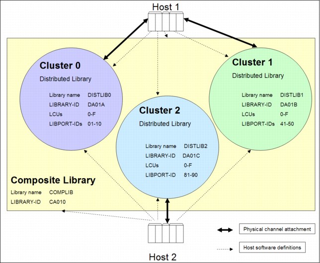
Figure 6-7 Example of a TS7700 Virtualization Engine three-cluster grid configuration
Using Figure 6-7 as an example, define Host 1 as having physical connections to Cluster 0 and Cluster 1. Cluster 2 and Host 2 are probably far away in a disaster recovery site and
Host 2 has only physical connections to Cluster 2. You then configure Host 1 with 512
(2 x 256) 3490E drives and Host 2 with 256 3490E drives. In HCD, you use the LIBRARY-ID from the composite library (CA010). Host 1 and Host 2 have three distributed libraries and one composite library defined to SMS. The three clusters are connected with an IP network.
LCUs and physical paths are defined on a vNode/gNode boundary, similar to the virtual tape controllers (VTCs) in the previous generation of the peer-to-peer Virtual Tape Server (VTS). All of them are part of the same composite library image presented to the host. Table 6-6 shows the subsystem IDs (LIBPORT-IDs) that you must use for each cluster in a four-cluster grid configuration.
Table 6-6 LIBPORT-ID for each cluster in a six-cluster grid configuration
|
Cluster
|
Logical control units (LCUs)
|
LIBPORT-IDs (hex)
|
|
0
|
0 - 7
|
01 - 08
|
|
8 - F
|
09 - 10
|
|
|
1
|
0 - 7
|
41 - 48
|
|
8 - F
|
49 - 50
|
|
|
2
|
0 - 7
|
81 - 88
|
|
8 - F
|
89 - 90
|
|
|
3
|
0 - 7
|
C1 - C8
|
|
8 - F
|
C9 - D0
|
|
|
4
|
0 - 7
|
21 - 28
|
|
8 - F
|
29 - 30
|
|
|
5
|
0 - 7
|
61 - 68
|
|
8 - F
|
69 - 70
|
The definition steps are essentially the same as for a stand-alone grid configuration. The important difference is that you need to specify the listed LIBPORT-IDs for all clusters forming the multicluster grid.
The virtual device allocation for each cluster in a two-cluster grid configuration is managed by the host. The host randomly picks a device from each cluster for an I/O operation based upon a host device allocation algorithm. Referencing Figure 6-7 on page 298, if the remote Cluster 2 is now attached through a limited bandwidth FICON connection to Host 1 or Host 2, it might negatively affect I/O performance. The possibility exists that the remote Cluster 2 might be selected as the I/O cluster, even if the data is residing in the Tape Volume Cache (TVC) of Cluster 0 or Cluster 1. To avoid those situations, vary offline the remote virtual devices from each host’s point for normal operation. Only vary those remote virtual drives online from the host in a disaster recovery situation. Other possibilities, such as device allocation assistance(DAA) and scratch allocation assistance (SAA), can also be used. For a detailed description, see Chapter 10, “Performance and monitoring” on page 653.
In your installation, you might have to review the FICON switch redundancy and performance objectives. Policies are based on requirements for data availability and accessibility. Your local policies might require that all FICON equipment must be attached through two FICON switches, with half of the connections on each.
If you have two data centers and FICON switch equipment at both sites connected to the hosts, use a cascading FICON switch configuration to attach to your tape subsystems. An alternate solution can be to connect the FICON connections directly from your local CPU to the switch in the remote center.
|
More information: For the latest information about supported FICON directors and TS7700 Virtualization Engine Licensed Internal Code levels, go to the following address:
An example of how to perform a cascading FICON attachment with two sites is at the following address:
|
6.2.4 More HCD and IOCP examples with a two-cluster grid
This section shows IOCP examples to help you get started.
Cluster 0, Composite LIBID = C0001 example
Figure 6-8 shows the configuration for IOCP definition.
Figure 6-8 Example configuration used for IOCP definition
Example 6-2 shows Cluster 0 IOCP.
Example 6-2 Cluster 0 IOCP
RESOURCE PARTITION=(LPAR0,1)
CHPID PATH=(48),SHARED,SWITCH=41,TYPE=FC
CHPID PATH=(4A),SHARED,SWITCH=42,TYPE=FC
CHPID PATH=(4C),SHARED,SWITCH=41,TYPE=FC
CHPID PATH=(4E),SHARED,SWITCH=42,TYPE=FC
CNTLUNIT CUNUMBER=(480),PATH=(48,4A,4C,4E ),UNIT=TAPE,UNITADD=((00,16)),LINK=(5306,5406,5308,5408),CUADD=0
IODEVICE ADDRESS=(2B00,16),UNIT=TAPE,CUNUMBER=(480),UNITADD=00,LIBID=C0001,LIBPORT=41
CNTLUNIT CUNUMBER=(481),PATH=(48,4A,4C,4E),UNIT=TAPE,UNITADD=((00,16)),LINK=(5306,5406,5308,5408),CUADD=1
IODEVICE ADDRESS=(2B10,16),UNIT=TAPE,CUNUMBER=(481),UNITADD=00,LIBID=C0001,LIBPORT=42
CNTLUNIT CUNUMBER=(482),PATH=(48,4A,4C,4E ),UNIT=TAPE,UNITADD=((00,16)),LINK=(5306,5406,5308,5408),CUADD=2
IODEVICE ADDRESS=(2B20,16),UNIT=TAPE,CUNUMBER=(482),UNITADD=00,LIBID=C0001,LIBPORT=43
CNTLUNIT CUNUMBER=(483),PATH=(48,4A,4C,4E),UNIT=TAPE,UNITADD=((00,16)),LINK=(5306,5406,5308,5408),CUADD=3
IODEVICE ADDRESS=(2B30,16),UNIT=TAPE,CUNUMBER=(483),UNITADD=00,LIBID=C0001,LIBPORT=44
CNTLUNIT CUNUMBER=(484),PATH=(48,4A,4C,4E ),UNIT=TAPE,UNITADD=((00,16)),LINK=(5306,5406,5308,5408),CUADD=4
IODEVICE ADDRESS=(2B40,16),UNIT=TAPE,CUNUMBER=(484),UNITADD=00,LIBID=C0001,LIBPORT=45
CNTLUNIT CUNUMBER=(485),PATH=(48,4A,4C,4E),UNIT=TAPE,UNITADD=((00,16)),LINK=(5306,5406,5308,5408),CUADD=5
IODEVICE ADDRESS=(2B50,16),UNIT=TAPE,CUNUMBER=(485),UNITADD=00,LIBID=C0001,LIBPORT=46
CNTLUNIT CUNUMBER=(486),PATH=(48,4A,4C,4E ),UNIT=TAPE,UNITADD=((00,16)),LINK=(5306,5406,5308,5408),CUADD=6
IODEVICE ADDRESS=(2B60,16),UNIT=TAPE,CUNUMBER=(486),UNITADD=00,LIBID=C0001,LIBPORT=47
CNTLUNIT CUNUMBER=(487),PATH=(48,4A,4C,4E),UNIT=TAPE,UNITADD=((00,16)),LINK=(5306,5406,5308,5408),CUADD=7
IODEVICE ADDRESS=(2B70,16),UNIT=TAPE,CUNUMBER=(487),UNITADD=00,LIBID=C0001,LIBPORT=48
CNTLUNIT CUNUMBER=(488),PATH=(48,4A,4C,4E ),UNIT=TAPE,UNITADD=((00,16)),LINK=(5306,5406,5308,5408),CUADD=8
IODEVICE ADDRESS=(2B80,16),UNIT=TAPE,CUNUMBER=(488),UNITADD=00,LIBID=C0001,LIBPORT=49
CNTLUNIT CUNUMBER=(489),PATH=(48,4A,4C,4E),UNIT=TAPE,UNITADD=((00,16)),LINK=(5306,5406,5308,5408),CUADD=9
IODEVICE ADDRESS=(2B90,16),UNIT=TAPE,CUNUMBER=(489),UNITADD=00,LIBID=C0001,LIBPORT=4A
CNTLUNIT CUNUMBER=(48A),PATH=(48,4A,4C,4E ),UNIT=TAPE,UNITADD=((00,16)),LINK=(5306,5406,5308,5408),CUADD=A
IODEVICE ADDRESS=(2BA0,16),UNIT=TAPE,CUNUMBER=(48A),UNITADD=00,LIBID=C0001,LIBPORT=4B
CNTLUNIT CUNUMBER=(48B),PATH=(48,4A,4C,4E),UNIT=TAPE,UNITADD=((00,16)),LINK=(5306,5406,5308,5408),CUADD=B
IODEVICE ADDRESS=(2BB0,16),UNIT=TAPE,CUNUMBER=(48B),UNITADD=00,LIBID=C0001,LIBPORT=4C
CNTLUNIT CUNUMBER=(48C),PATH=(48,4A,4C,4E ),UNIT=TAPE,UNITADD=((00,16)),LINK=(5306,5406,5308,5408),CUADD=C
IODEVICE ADDRESS=(2BC0,16),UNIT=TAPE,CUNUMBER=(48C),UNITADD=00,LIBID=C0001,LIBPORT=4D
CNTLUNIT CUNUMBER=(48D),PATH=(48,4A,4C,4E),UNIT=TAPE,UNITADD=((00,16)),LINK=(5306,5406,5308,5408),CUADD=D
IODEVICE ADDRESS=(2BD0,16),UNIT=TAPE,CUNUMBER=(48D),UNITADD=00,LIBID=C0001,LIBPORT=4E
CNTLUNIT CUNUMBER=(48E),PATH=(48,4A,4C,4E ),UNIT=TAPE,UNITADD=((00,16)),LINK=(5306,5406,5308,5408),CUADD=E
IODEVICE ADDRESS=(2BE0,16),UNIT=TAPE,CUNUMBER=(48E),UNITADD=00,LIBID=C0001,LIBPORT=4F
CNTLUNIT CUNUMBER=(48F),PATH=(48,4A,4C,4E),UNIT=TAPE,UNITADD=((00,16)),LINK=(5306,5406,5308,5408),CUADD=F
IODEVICE ADDRESS=(2BF0,16),UNIT=TAPE,CUNUMBER=(48F),UNITADD=00,LIBID=C0001,LIBPORT=50
Cluster 1, Composite LIBID = C0001 example
Figure 6-9 shows cluster configuration for IOCP.

Figure 6-9 Cluster configuration for IOCP
Example 6-3 shows Cluster 1 IOCP.
Example 6-3 Cluster 1 IOCP
CHPID PATH=(58),SHARED,SWITCH=61,TYPE=FC
CHPID PATH=(5A),SHARED,SWITCH=62,TYPE=FC
CHPID PATH=(5C),SHARED,SWITCH=61,TYPE=FC
CHPID PATH=(5E),SHARED,SWITCH=62,TYPE=FC
CNTLUNIT CUNUMBER=(440),PATH=(58,5A,5C,5E ),UNIT=TAPE,UNITADD=((00,16)),LINK=(7306,7406,7308,7408),CUADD=0
IODEVICE ADDRESS=(2A00,16),UNIT=TAPE,CUNUMBER=(440),UNITADD=00,LIBID=C0001,LIBPORT=01
CNTLUNIT CUNUMBER=(441),PATH=(58,5A,5C,5E),UNIT=TAPE,UNITADD=((00,16)),LINK=(7306,7406,7308,7408),CUADD=1
IODEVICE ADDRESS=(2A10,16),UNIT=TAPE,CUNUMBER=(441),UNITADD=00,LIBID=C0001,LIBPORT=02
CNTLUNIT CUNUMBER=(442),PATH=(58,5A,5C,5E ),UNIT=TAPE,UNITADD=((00,16)),LINK=(7306,7406,7308,7408),CUADD=2
IODEVICE ADDRESS=(2A20,16),UNIT=TAPE,CUNUMBER=(442),UNITADD=00,LIBID=C0001,LIBPORT=03
CNTLUNIT CUNUMBER=(443),PATH=(58,5A,5C,5E),UNIT=TAPE,UNITADD=((00,16)),LINK=(7306,7406,7308,7408),CUADD=3
IODEVICE ADDRESS=(2A30,16),UNIT=TAPE,CUNUMBER=(443),UNITADD=00,LIBID=C0001,LIBPORT=04
CNTLUNIT CUNUMBER=(444),PATH=(58,5A,5C,5E ),UNIT=TAPE,UNITADD=((00,16)),LINK=(7306,7406,7308,7408),CUADD=4
IODEVICE ADDRESS=(2A40,16),UNIT=TAPE,CUNUMBER=(444),UNITADD=00,LIBID=C0001,LIBPORT=05
CNTLUNIT CUNUMBER=(445),PATH=(58,5A,5C,5E),UNIT=TAPE,UNITADD=((00,16)),LINK=(7306,7406,7308,7408),CUADD=5
IODEVICE ADDRESS=(2A50,16),UNIT=TAPE,CUNUMBER=(445),UNITADD=00,LIBID=C0001,LIBPORT=06
CNTLUNIT CUNUMBER=(446),PATH=(58,5A,5C,5E ),UNIT=TAPE,UNITADD=((00,16)),LINK=(7306,7406,7308,7408),CUADD=6
IODEVICE ADDRESS=(2A60,16),UNIT=TAPE,CUNUMBER=(446),UNITADD=00,LIBID=C0001,LIBPORT=07
CNTLUNIT CUNUMBER=(447),PATH=(58,5A,5C,5E),UNIT=TAPE,UNITADD=((00,16)),LINK=(7306,7406,7308,7408),CUADD=7
IODEVICE ADDRESS=(2A70,16),UNIT=TAPE,CUNUMBER=(447),UNITADD=00,LIBID=C0001,LIBPORT=08
CNTLUNIT CUNUMBER=(448),PATH=(58,5A,5C,5E ),UNIT=TAPE,UNITADD=((00,16)),LINK=(7306,7406,7308,7408),CUADD=8
IODEVICE ADDRESS=(2A80,16),UNIT=TAPE,CUNUMBER=(448),UNITADD=00,LIBID=C0001,LIBPORT=09
CNTLUNIT CUNUMBER=(449),PATH=(58,5A,5C,5E),UNIT=TAPE,UNITADD=((00,16)),LINK=(7306,7406,7308,7408),CUADD=9
IODEVICE ADDRESS=(2A90,16),UNIT=TAPE,CUNUMBER=(449),UNITADD=00,LIBID=C0001,LIBPORT=0A
CNTLUNIT CUNUMBER=(44A),PATH=(58,5A,5C,5E ),UNIT=TAPE,UNITADD=((00,16)),LINK=(7306,7406,7308,7408),CUADD=A
IODEVICE ADDRESS=(2AA0,16),UNIT=TAPE,CUNUMBER=(44A),UNITADD=00,LIBID=C0001,LIBPORT=0B
CNTLUNIT CUNUMBER=(44B),PATH=(58,5A,5C,5E),UNIT=TAPE,UNITADD=((00,16)),LINK=(7306,7406,7308,7408),CUADD=B
IODEVICE ADDRESS=(2AB0,16),UNIT=TAPE,CUNUMBER=(44B),UNITADD=00,LIBID=C0001,LIBPORT=0C
CNTLUNIT CUNUMBER=(44C),PATH=(58,5A,5C,5E ),UNIT=TAPE,UNITADD=((00,16)),LINK=(7306,7406,7308,7408),CUADD=C
IODEVICE ADDRESS=(2AC0,16),UNIT=TAPE,CUNUMBER=(44C),UNITADD=00,LIBID=C0001,LIBPORT=0D
CNTLUNIT CUNUMBER=(44D),PATH=(58,5A,5C,5E),UNIT=TAPE,UNITADD=((00,16)),LINK=(7306,7406,7308,7408),CUADD=D
IODEVICE ADDRESS=(2AD0,16),UNIT=TAPE,CUNUMBER=(44D),UNITADD=00,LIBID=C0001,LIBPORT=0E
CNTLUNIT CUNUMBER=(44E),PATH=(58,5A,5C,5E ),UNIT=TAPE,UNITADD=((00,16)),LINK=(7306,7406,7308,7408),CUADD=E
IODEVICE ADDRESS=(2AE0,16),UNIT=TAPE,CUNUMBER=(44E),UNITADD=00,LIBID=C0001,LIBPORT=0F
CNTLUNIT CUNUMBER=(44F),PATH=(58,5A,5C,5E),UNIT=TAPE,UNITADD=((00,16)),LINK=(7306,7406,7308,7408),CUADD=F
IODEVICE ADDRESS=(2AF0,16),UNIT=TAPE,CUNUMBER=(44F),UNITADD=00,LIBID=C0001,LIBPORT=10
6.2.5 Display and control your settings
In a z/OS environment, you can use the DISPLAY SMS and DEVSERV QUERY LIBRARY commands to check portions of your definitions.
DISPLAY SMS command in TS7700 Virtualization Engine
You can use the DISPLAY SMS command to display and check the settings in the DEVSUPxx member for the scratch categories, as shown in the following example:
DISPLAY SMS,LIBRARY(lib_name),DETAIL
|
Remember: The scratch count of MEDIA2 does not necessarily match the number of scratch volumes of your tape management system when you use the Expire Hold function in the TS7700 Virtualization Engine. The object access method (OAM) displays the scratch count it receives from the TS7700 Virtualization Engine.
|
Example 6-4 shows the sample output of a DISPLAY SMS,LIBRARY command against the composite library, in this case, for a mixed grid with both TS7720 and TS7740 distributed libraries. The host from which this command was issued is using scratch category 5001 for MEDIA1 and scratch category 5002 for MEDIA2. There might be differences in the Device Type field depending on your configuration. For a mixed grid configuration, the device type is GRID. In a grid consisting of TS7720 clusters only, it is 3957-VEA or 3957-VEB. In a pure TS7740 grid, a device type of 3957-V06 or 3957-V07 is displayed.
Example 6-4 Display SMS,LIB from the TS7700 Virtualization Engine composite library
D SMS,LIB(BARR68),DETAIL
F OAM,D,LIB,BARR68,L=SCOTTMR-Z
CBR1110I OAM LIBRARY STATUS: 110
TAPE LIB DEVICE TOT ONL AVL TOTAL EMPTY SCRTCH ON OP
LIBRARY TYP TYPE DRV DRV DRV SLOTS SLOTS VOLS
BARR68 VCL GRID 1536 256 256 0 0 2681012 Y Y
----------------------------------------------------------------------
MEDIA SCRATCH SCRATCH SCRATCH
TYPE COUNT THRESHOLD CATEGORY
MEDIA1 366736 0 5001
MEDIA2 314276 0 5002
----------------------------------------------------------------------
DISTRIBUTED LIBRARIES: BARR68A BARR68B BARR68C BARR68D BARR68E
DISTRIBUTED LIBRARIES: BARR68F
----------------------------------------------------------------------
LIBRARY ID: BA068
OPERATIONAL STATE: AUTOMATED
ERROR CATEGORY SCRATCH COUNT: 1
CORRUPTED TOKEN VOLUME COUNT: 1
----------------------------------------------------------------------
LIBRARY SUPPORTS OUTBOARD POLICY MANAGEMENT.
LIBRARY SUPPORTS LOGICAL WORM.
Example 6-5 on page 303 shows the sample output of a DISPLAY SMS,LIBRARY command against one of the TS77040 distributed libraries in the grid.
Example 6-5 Display SMS,LIB from a TS7740 Virtualization Engine distributed library
D SMS,LIB(BARR68A),DETAIL
F OAM,D,LIB,BARR68A,L=SCOTTMR-Z
CBR1110I OAM LIBRARY STATUS: 873
TAPE LIB DEVICE TOT ONL AVL TOTAL EMPTY SCRTCH ON OP
LIBRARY TYP TYPE DRV DRV DRV SLOTS SLOTS VOLS
BARR68A VDL 3957-V07 0 0 0 6887 4070 0 Y Y
----------------------------------------------------------------------
COMPOSITE LIBRARY: BARR68
----------------------------------------------------------------------
LIBRARY ID: BA68A
OPERATIONAL STATE: AUTOMATED
SCRATCH STACKED VOLUME COUNT: 2029
PRIVATE STACKED VOLUME COUNT: 780
----------------------------------------------------------------------
LIBRARY SUPPORTS IMPORT/EXPORT.
LIBRARY SUPPORTS OUTBOARD POLICY MANAGEMENT.
LIBRARY SUPPORTS LOGICAL WORM.
CONVENIENCE I/O STATION INSTALLED.
CONVENIENCE I/O STATION IN OUTPUT MODE.
CONVENIENCE I/O STATION EMPTY.
BULK INPUT/OUTPUT NOT CONFIGURED.
DISPLAY SMS command for the TS7720 Virtualization Engine
For the TS7720 Virtualization Engine, the output differs slightly. Example 6-6 shows the output of DISPLAY SMS,LIBRARY for one of the TS7720 distributed libraries in the grid.
Example 6-6 Display SMS,LIB from a TS7720 Virtualization Engine distributed library
D SMS,LIB(BARR68D),DETAIL
F OAM,D,LIB,BARR68D,L=SCOTTMR-Z
CBR1110I OAM LIBRARY STATUS: 272
TAPE LIB DEVICE TOT ONL AVL TOTAL EMPTY SCRTCH ON OP
LIBRARY TYP TYPE DRV DRV DRV SLOTS SLOTS VOLS
BARR68D VDL 3957-VEB 0 0 0 0 0 0 Y Y
----------------------------------------------------------------------
COMPOSITE LIBRARY: BARR68
----------------------------------------------------------------------
LIBRARY ID: BA68D
CACHE PERCENTAGE USED: 35
OPERATIONAL STATE: AUTOMATED
----------------------------------------------------------------------
LIBRARY SUPPORTS OUTBOARD POLICY MANAGEMENT.
LIBRARY SUPPORTS LOGICAL WORM.
The important fields of the TS7720 Virtualization Engine distributed library are shown in the output of D SMS,LIBRARY,(BARR68D),DETAIL:
•The device type is 3957-VEB.
•The amount of cache used is listed.
•The number of TOTAL SLOTS and EMPTY SLOTS is always 0.
•As there are no cartridges to manage, there is no I/O station.
•The SCRATCH and PRIVATE STACKED lines are suppressed.
There are many additional states that can be reported (if the library is in the associated state) with the DISPLAY SMS command. Some of the more TS7700-specific states are listed:
•LIMTED CACHE FREE SPACE - Warning State (TS7720 Virtualization Engine only)
•OUT OF CACHE RESOURCES - Critical State (TS7720 Virtualization Engine only)
•FORCE PAUSE OCCURRED
•GRID LINKS DEGRADED
•VTS OPERATIONS DEGRADED
DEVSERV QUERY LIBRARY command
When making changes to the libraries, always use the DEVSERV QUERY LIBRARY or DS QL command to query your library configuration before and after an activation of your IODF. You can query both a composite library and a distributed library.
The new command DS QLIB,CATS allows you to view and change logical VOLSER categories without need to IPL the system, but be careful when you use this command. Example 6-7 shows how to list all categories used in a system.
Example 6-7 Sample output of DEVSERV QLIB,CATS
DS QL,CATS
IEE459I 10.56.27 DEVSERV QLIB 626
5001 5002 5003 5004 5005 5006 5007 5008 5009 500A 500B 500C 500D
500E 500F
After you have the actual categories, you can change them. To perform that task, change the first three digits of the category. However, the last digit must remain unchanged because it represents the media type.
Example 6-8 shows the command that changes all categories to 111 for the first three digits.
Example 6-8 Sample output of DEVSERV QLIB,CATS(111*)
DS QL,CATS(111*)
IEE459I 10.57.35 DEVSERV QLIB 899
1111 1112 1113 1114 1115 1116 1117 1118 1119 111A 111B 111C 111D
111E 111F
Ensure that this change is made in the DEVSUPxx PARMLIB member. Otherwise, the next initial program load (IPL) will revert categories to what they were in DEVSUPxx.
|
Remember: Be aware of the potential risks of changing scratch categories in a running system. If you alter the MEDIA2 scratch category and there are no logical volumes in this altered scratch category in the TS7700 Virtualization Engine, all scratch mounts will fail.
|
Example 6-9 shows how you list all the active composite libraries using the DS QL command. The QLIB command uses the LIBRARY-IDs (LIBIDs), not the TAPE LIBRARY NAME that was used in the D SMS,LIB command.
Example 6-9 DEVSERV QLIB,LIST
DS QL,LIST
IEE459I 09.39.33 DEVSERV QLIB 933
The following are defined in the ACTIVE configuration:
*BA062 *CA045 *BA060 *BA045 *BA003 *BA031 *BA032 *BA002 *BA039 *BA038
*BA010 BA066 BA051 BA004
|
Note: The asterisks in the QLIB displays indicate libraries that are actually attached to the host.
|
Example 6-10 shows a DEVSERV QLIB command issued against composite library BA003. It shows the virtual devices of the distributed libraries belonging to this composite library. This is a stand-alone configuration with a single TS7740 so there is only one DISTRIBUTED LIBID listed. In a multicluster grid, all the distributed libraries defined to this composite library are listed.
Example 6-10 Sample output of DEVSERV QLIB for a composite library
DS QL,BA003
IEE459I 11.07.56 DEVSERV QLIB 970
The following are defined in the ACTIVE configuration:
LIBID PORTID DEVICES
BA003 06 8F5A* 8F5B* 8F5C* 8F5D* 8F5E* 8F5F* 8F50* 8F51*
8F52* 8F53* 8F54* 8F55* 8F56* 8F57* 8F58* 8F59*
02 8F1A* 8F1B* 8F1C* 8F1D* 8F1E* 8F1F* 8F10* 8F11*
8F12* 8F13* 8F14* 8F15* 8F16* 8F17* 8F18* 8F19*
04 8F3A* 8F3B* 8F3C* 8F3D* 8F3E* 8F3F* 8F30* 8F31*
8F32* 8F33* 8F34* 8F35* 8F36* 8F37* 8F38* 8F39*
08 8F7A* 8F7B* 8F7C* 8F7D* 8F7E* 8F7F* 8F70* 8F71*
8F72* 8F73* 8F74* 8F75* 8F76* 8F77* 8F78* 8F79*
0C 8FBA* 8FBB* 8FBC* 8FBD* 8FBE* 8FBF* 8FB0* 8FB1*
8FB2* 8FB3* 8FB4* 8FB5* 8FB6* 8FB7* 8FB8* 8FB9*
10 8FFA* 8FFB* 8FFC* 8FFD* 8FFE* 8FFF* 8FF0* 8FF1*
8FF2* 8FF3* 8FF4* 8FF5* 8FF6* 8FF7* 8FF8* 8FF9*
0E 8FDA* 8FDB* 8FDC* 8FDD* 8FDE* 8FDF* 8FD0* 8FD1*
8FD2* 8FD3* 8FD4* 8FD5* 8FD6* 8FD7* 8FD8* 8FD9*
0A 8F9A* 8F9B* 8F9C* 8F9D* 8F9E* 8F9F* 8F90* 8F91*
8F92* 8F93* 8F94* 8F95* 8F96* 8F97* 8F98* 8F99*
01 8F00* 8F01* 8F02* 8F03* 8F04* 8F05* 8F06* 8F07*
8F08* 8F09* 8F0A* 8F0B* 8F0C* 8F0D* 8F0E* 8F0F*
03 8F20* 8F21* 8F22* 8F23* 8F24* 8F25* 8F26* 8F27*
8F28* 8F29* 8F2A* 8F2B* 8F2C* 8F2D* 8F2E* 8F2F*
05 8F40* 8F41* 8F42* 8F43* 8F44* 8F45* 8F46* 8F47*
8F48* 8F49* 8F4A* 8F4B* 8F4C* 8F4D* 8F4E* 8F4F*
07 8F60* 8F61* 8F62* 8F63* 8F64* 8F65* 8F66* 8F67*
8F68* 8F69* 8F6A* 8F6B* 8F6C* 8F6D* 8F6E* 8F6F*
09 8F80* 8F81* 8F82* 8F83* 8F84* 8F85* 8F86* 8F87*
8F88* 8F89* 8F8A* 8F8B* 8F8C* 8F8D* 8F8E* 8F8F*
0B 8FA0* 8FA1* 8FA2* 8FA3* 8FA4* 8FA5* 8FA6* 8FA7*
8FA8* 8FA9* 8FAA* 8FAB* 8FAC* 8FAD* 8FAE* 8FAF*
0D 8FC0* 8FC1* 8FC2* 8FC3* 8FC4* 8FC5* 8FC6* 8FC7*
8FC8* 8FC9* 8FCA* 8FCB* 8FCC* 8FCD* 8FCE* 8FCF*
0F 8FE0* 8FE1* 8FE2* 8FE3* 8FE4* 8FE5* 8FE6* 8FE7*
8FE8* 8FE9* 8FEA* 8FEB* 8FEC* 8FED* 8FEE* 8FEF*
DISTRIBUTED LIBID(S)
BA03A*
Example 6-11 shows a list of the devices belonging to a single distributed library using the DEVSERV QLIB command. Check that no duplicate port IDs are listed and that each port has 16 devices. This is the correct output for a TS7700 Virtualization Engine.
Example 6-11 Sample output of the DEVSERV QLIB command against a single distributed library
DS QL,BA03A
IEE459I 11.12.02 DEVSERV QLIB 840
The following are defined in the ACTIVE configuration:
LIBID PORTID DEVICES
BA03A 06 8F5A* 8F5B* 8F5C* 8F5D* 8F5E* 8F5F* 8F50* 8F51*
8F52* 8F53* 8F54* 8F55* 8F56* 8F57* 8F58* 8F59*
02 8F1A* 8F1B* 8F1C* 8F1D* 8F1E* 8F1F* 8F10* 8F11*
8F12* 8F13* 8F14* 8F15* 8F16* 8F17* 8F18* 8F19*
04 8F3A* 8F3B* 8F3C* 8F3D* 8F3E* 8F3F* 8F30* 8F31*
8F32* 8F33* 8F34* 8F35* 8F36* 8F37* 8F38* 8F39*
08 8F7A* 8F7B* 8F7C* 8F7D* 8F7E* 8F7F* 8F70* 8F71*
8F72* 8F73* 8F74* 8F75* 8F76* 8F77* 8F78* 8F79*
0C 8FBA* 8FBB* 8FBC* 8FBD* 8FBE* 8FBF* 8FB0* 8FB1*
8FB2* 8FB3* 8FB4* 8FB5* 8FB6* 8FB7* 8FB8* 8FB9*
10 8FFA* 8FFB* 8FFC* 8FFD* 8FFE* 8FFF* 8FF0* 8FF1*
8FF2* 8FF3* 8FF4* 8FF5* 8FF6* 8FF7* 8FF8* 8FF9*
0E 8FDA* 8FDB* 8FDC* 8FDD* 8FDE* 8FDF* 8FD0* 8FD1*
8FD2* 8FD3* 8FD4* 8FD5* 8FD6* 8FD7* 8FD8* 8FD9*
0A 8F9A* 8F9B* 8F9C* 8F9D* 8F9E* 8F9F* 8F90* 8F91*
8F92* 8F93* 8F94* 8F95* 8F96* 8F97* 8F98* 8F99*
01 8F00* 8F01* 8F02* 8F03* 8F04* 8F05* 8F06* 8F07*
8F08* 8F09* 8F0A* 8F0B* 8F0C* 8F0D* 8F0E* 8F0F*
03 8F20* 8F21* 8F22* 8F23* 8F24* 8F25* 8F26* 8F27*
8F28* 8F29* 8F2A* 8F2B* 8F2C* 8F2D* 8F2E* 8F2F*
05 8F40* 8F41* 8F42* 8F43* 8F44* 8F45* 8F46* 8F47*
8F48* 8F49* 8F4A* 8F4B* 8F4C* 8F4D* 8F4E* 8F4F*
07 8F60* 8F61* 8F62* 8F63* 8F64* 8F65* 8F66* 8F67*
8F68* 8F69* 8F6A* 8F6B* 8F6C* 8F6D* 8F6E* 8F6F*
09 8F80* 8F81* 8F82* 8F83* 8F84* 8F85* 8F86* 8F87*
8F88* 8F89* 8F8A* 8F8B* 8F8C* 8F8D* 8F8E* 8F8F*
0B 8FA0* 8FA1* 8FA2* 8FA3* 8FA4* 8FA5* 8FA6* 8FA7*
8FA8* 8FA9* 8FAA* 8FAB* 8FAC* 8FAD* 8FAE* 8FAF*
0D 8FC0* 8FC1* 8FC2* 8FC3* 8FC4* 8FC5* 8FC6* 8FC7*
8FC8* 8FC9* 8FCA* 8FCB* 8FCC* 8FCD* 8FCE* 8FCF*
0F 8FE0* 8FE1* 8FE2* 8FE3* 8FE4* 8FE5* 8FE6* 8FE7*
8FE8* 8FE9* 8FEA* 8FEB* 8FEC* 8FED* 8FEE* 8FEF*
COMPOSITE LIBID
BA003
You can display the command syntax in the following manner:
DS QL,?
For a complete description of the QLIB command, see the following resources:
•z/OS MVS System Commands, SA22-7627
6.2.6 Set values for the Missing Interrupt Handler
The TS7700 Virtualization Engine emulates 3490E devices and does not automatically communicate the Missing Interrupt Handler (MIH) timeout values to the host operating system in the Read Configuration Data Channel Control Word (CCW).
|
Important: An MIH value of 45 minutes is preferable for the virtual devices in a multicluster grid when a copy consistency for the remote clusters is set to RUN.
|
You must specify the MIH timeout value for IBM 3490E devices. The value applies only to the virtual 3490E drives and not to the real IBM TS1140/TS1130/TS1120/3592 drives that the TS7740 Virtualization Engine manages in the back end. Remember that the host only knows about logical 3490E devices.
Table 6-7 summarizes the minimum values, which might need to be increased, depending on specific operational factors.
Table 6-7 Tape device MIH values
|
Tape device
|
MIH
|
|
TS7700 Virtualization Engine stand-alone grid with 3490E emulation drives
|
20 minutes
|
|
TS7700 Virtualization Engine multicluster grid with 3490E emulation drives
|
45 minutes
|
Specify the MIH values in PARMLIB member IECIOSxx. Alternatively, you can also set the MIH values through the System z operator command SETIOS. This setting is available until it is manually changed or until the system is initialized.
Use the following statements in PARMLIB, or manual commands to display and set your MIH values:
•You can specify the MIH value in the IECIOSxx PARMLIB member:
MIH DEV=(0A40-0A7F),TIME=45:00
•To manually specify MIH values for emulated 3490E tape drives, use this command:
SETIOS MIH,DEV=(0A40-0A7F),TIME=45:00
– To display the new settings, use this command:
D IOS,MIH,DEV=0A40
– To check the current MIH time, use this command:
D IOS,MIH,TIME=TAPE
More information about MIH settings is available in MVS Initialization and Tuning Reference, SA22-7592.
During IPL (if the device is defined to be ONLINE) or during the VARY ONLINE in process, some devices might present their own MIH timeout values through the primary/secondary MIH timing enhancement that is contained in the self-describing data for the device. The primary MIH timeout value is used for most I/O commands, but the secondary MIH timeout value can be used for special operations, such as long-busy conditions or long-running I/O operations.
Any time that a user specifically sets a device or device class to an MIH timeout value that is different from the default for the device class that is set by IBM, that value will override the device-established primary MIH timeout value. This implies that if an MIH timeout value that is equal to the MIH default for the device class is explicitly requested, IOS will not override the device-established primary MIH timeout value. To override the device-established primary MIH timeout value, you must explicitly set a timeout value that is not equal to the MIH default for the device class.
|
Important: Overriding the device-supplied primary MIH timeout value might adversely affect MIH recovery processing for the device or device class.
|
See the specific device’s reference manuals to determine whether the device supports self-describing MIH timeout values.
6.3 TS7700 Virtualization Engine software definitions for z/OS
This section describes the software definition considerations for implementing the TS7700 Virtualization Engine in z/OS, VM/ESA, and z/VSE environments. From a software point of view, the TS7700 Virtualization Engine is the same as an IBM 3494 Enterprise Tape Library with IBM 3490E Tape Drives.
The TS7700 Virtualization Engine must be defined as a new tape library with emulated 3490E Tape Drives from the host system. See IBM TotalStorage 3494 Tape Library: A Practical Guide to Tape Drives and Tape Automation, SG24-46322, for more information about defining this configuration.
The software levels required to support a TS7700 Virtualization Engine are explained in 4.5.2, “Software requirements” on page 159.
Tape management systems
From the host perspective, a TS7700 Virtualization Engine is a single automated tape subsystem whether it is a stand-alone cluster configuration or a multicluster grid configuration. The tape management system sees only the composite library and logical drives. There is no difference from the tape management system’s point of view between a multicluster grid TS7700 Virtualization Engine installation (peer-to-peer) and a stand-alone cluster installation (stand-alone).
6.3.1 z/OS and DFSMS/MVS system-managed tape
To define the TS7700 Virtualization Engine to DFSMS, use the Interactive Storage Management Facility (ISMF) panels to create a new definition of the TS7700 Virtualization Engine logical tape library to be recognized from the host. This definition is done in the same way for a new installation of a stand-alone grid as it is done for a new installation of a multicluster grid TS7700 Virtualization Engine, with the exception of distributed library definitions:
•In a stand-alone cluster configuration, you define one composite library and one distributed library.
•In a multicluster configuration, you define one composite library and two, three, four, five, or six distributed libraries.
To use the TS7700 Virtualization Engine, at least one Storage Group must be created to allow the TS7700 Virtualization Engine tape library virtual drives to be allocated by the SMS ACS routines. Because all of the logical drives and volumes are associated with the composite library, only the composite library can be defined in the Storage Group. The distributed libraries must not be defined in the Storage Group.
See the following resources for information about host software implementation tasks for IBM tape libraries:
•z/OS DFSMS OAM Planning, Installation, and Storage Administration Guide for Tape Libraries, SC35-0427
•IBM TS3500 Tape Library with System z Attachment A Practical Guide to Enterprise Tape Drives and TS3500 Tape Automation, SG24-6789
Perform the following steps to define the TS7700 Virtualization Engine Tape Library in a z/OS environment:
1. Modify the SYS1.PARMLIB member (such as IEFSSNxx, IGDSMSxx, LOADxx, DEVSUPxx, or COMMANDxx).
2. Using IDCAMS, define the tape configuration database (TCDB) as an ICF catalog using the DEFINE USERCATALOG command with keyword VOLCAT.
3. Use the IDCAMS IMPORT CONNECT command to connect the TCDB to the other systems in the sysplex where it will be shared. This does not need to be done on the system where the TCDB was first created, it will be connected during the DEFINE process on that system.
4. Add the procedure to start the OAM address space if it does not already exist.
5. Use the ISMF panels to define the tape library as a DFSMS resource. Define the composite library and one or more distributed libraries. Remember that library names cannot start with a “V”.
Figure 6-10 shows the definition of a composite library.
|
window Utilities Scroll Help
------------------------------------------------------------------------------
TAPE LIBRARY DEFINE Page 1 of 2
Command ===>_
SCDS Name . : SCDS.TEMP.PRIMARY
Library Name : IBMC1
To Define Library, Specify:
Description ===> TS7700 Grid Composite library
===>
Library ID . . . . . . . . . . .CA010 (00001 to FFFFF)
Console Name . . . . . . . . . .LIB1CON
Entry Default Data Class . . . .DCATLDS
Entry Default Use Attribute . . S (P=PRIVATE or S=SCRATCH)
Eject Default . . . . . . . . . K (P=PURGE or K=KEEP)
Media Type: Scratch Threshold
Media1 . . . . 100 Media3 . . . . 0 (0 to 999999)
Media2 . . . . 400 Media4 . . . . 0 (0 to 999999)
Use ENTER to Perform Verification; Use DOWN Command to View Next window;
Use HELP Command for Help; Use END Command to Save and Exit; CANCEL to Exit.
|
Figure 6-10 Composite library definition
Figure 6-11 shows a sample window that defines one of the distributed libraries.
|
window Utilities Scroll Help
------------------------------------------------------------------------------
TAPE LIBRARY DEFINE Page 1 of 2
Command ===>_
SCDS Name . : SCDS.TEMP.PRIMARY
Library Name : IBMD1TU
To Define Library, Specify:
Description ===> TS7700 Distributed library A
===>
Library ID . . . . . . . . . . .D1312 (00001 to FFFFF)
Console Name . . . . . . . . . .
Entry Default Data Class . . . .
Entry Default Use Attribute . . (P=PRIVATE or S=SCRATCH)
Eject Default . . . . . . . . . (P=PURGE or K=KEEP)
Media Type: Scratch Threshold
Media1 . . . . 0 Media3 . . . . 0 (0 to 999999)
Media2 . . . . 0 Media4 . . . . 0 (0 to 999999)
Use ENTER to Perform Verification; Use DOWN Command to View Next window;
Use HELP Command for Help; Use END Command to Save and Exit; CANCEL to Exit.
|
Figure 6-11 Distributed library definition
|
Remember: Library ID is the only field that applies for the distributed libraries. All other fields can be blank or left as the default.
|
6. Using ISMF, create or update the Data Classes (DCs), Storage Classes (SCs), and Management Classes (MCs) for the TS7700 Virtualization Engine. Ensure that these defined construct names are the same as those you have defined at the TS7700 Virtualization Engine management interface (MI).
7. Using ISMF, create the Storage Groups (SGs) for the TS7700 Virtualization Engine. Ensure that these defined construct names are the same as those you have defined at the TS7700 Virtualization Engine MI.
The composite library must be defined in the Storage Group. Do not define the distributed libraries in the Storage Group.
|
Tip: At OAM address space initialization, if a distributed library is defined to a Storage Group, the warning message CBR3017I is issued indicating that the distributed library is incorrectly defined to the Storage Group.
|
8. Update the ACS routines to assign the constructs, translate, test, and validate the ACS routines.
9. Activate the new Source Control Data Set (SCDS) with the SETSMS SCDS command.
10. SCDS activation will initiate an OAM restart if parameter RESTART=YES is specified in the OAM startup procedure in PROCLIB. If RESTART=NO is used, you must issue an OAM restart command manually using the F OAM,RESTART command. Example 6-12 shows a sample OAM procedure where RESTART=NO is used.
Example 6-12 OAM start-up procedure from PROCLIB
//OAM PROC
//IEFPROC EXEC PGM=CBROAM,REGION=0M,
// PARM=('OSMC=NO,APLAN=CBROAM,OAM=60,MAXS=2,RESTART=NO')
//SYSABEND DD SYSOUT=A
11. Vary the composite library and distributed libraries online.
12. Vary the TS7700 Virtualization Engine virtual drives online.
For more detailed information about defining a tape subsystem in a DFSMS environment, see IBM TS3500 Tape Library with System z Attachment A Practical Guide to Enterprise Tape Drives and TS3500 Tape Automation, SG24-6789.
|
Clarification: The CBRXLCS FUNC=PTPDATA and FUNC=PTPMC programming interfaces are not supported in the TS7700 Virtualization Engine. If invoked, these functions fail with Return Code 12, Reason Code 322, 'Command rejected by the library'.
|
6.4 Implementing Selective Device Access Control
This section explains how to implement Selective Device Access Control (SDAC). The function is a new common feature from TS7700 Virtualization Engine R2.0. SDAC allows you to perform a hard partitioning of the available devices and volume ranges for a host plex, when several host plexes share the same composite library. It supports the ability to enable hard partitioning at LIBPORT-ID granularity. It enables exclusive control on host-initiated mount, eject, and attribute or category changes.
The primary intended use of SDAC is to prevent one host logical partition (LPAR)/sysplex with an independent tape management configuration from inadvertently modifying or removing data owned by another host. Also, use SDAC to prevent applications and users on one system from accessing active data on volumes owned by another system.
A use case for the feature can be a client that uses a service provider. The service provider uses one composite library to deliver the services needed for all sysplexes:
•Each sysplex uses its own scratch categories based on logical partitioning. See 6.1.2, “Partitioning the TS7700 Virtualization Engine between multiple hosts” on page 287.
•Each sysplex uses its own unique volume ranges and independent tape management system (that is, Removable Media Management (RMM) or CA-1)
•The service provider owns the host and therefore has exclusive access to the IODF settings for each sysplex.
•Access to the MI must be the responsibility of the service provider and access to the MI must be restricted.
•IODF is defined within the System z host, by the service provider, to determine which device ranges and associated Library Port IDs are configured for a particular LPAR/sysplex. You assign a range of volumes to be mutually exclusive to that set of Library Port IDs.
•IBM RACF security or an equivalent product is used to protect the IODF data set.
•Tape volumes and data sets on tape volumes are protected by PACF. To perform this part and to get more detailed information about RACF and tape, see z/OS V1R13.0 DFSMSrmm Implementation and Customization Guide, SC26-7405.
The function can be active on new volume ranges and existing ranges. An example with three hosts using SDAC is shown in Figure 6-12.

Figure 6-12 SDAC with three hosts
6.4.1 Implementation of SDAC in z/OS
You define the number of CUs and devices for each host after a thorough evaluation of how many devices are needed from each of the connected clusters. The definitions must match the definitions made on the MI.
The correct volume ranges must be defined in your Tape Management System. Example 6-13 shows what happens in z/OS when a job tries to read data from a volume when the volume ranges are “hard-partitioned” and belong to another host. The job will fail.
Example 6-13 SDAC and unauthorized access to a logical volume
11.15.36 JOB21356 IEF233A M 8EB8,100066,,TAB64800,CMPR000
11.15.36 JOB21356 JOB=TAB64800 STEP=CMPR000 PGM=IEBGENER NOT EXECUTED
11.15.37 JOB21356 IEF453I TAB64800 - JOB FAILED - JCL ERROR - TIME=11.15.37
IEF116I TAB64800 CMPR000 - MOUNT OF VOLUME 100066 ON DEVICE 8EB8 FAILED
IEE763I NAME= CBRLLACS CODE= 140198
CBR4000I LACS MOUNT PERMANENT ERROR FOR DRIVE 8EB8.
CBR4175I VOLUME 100066 LIBRARY BARR64 ACCESS GROUP DENIES MOUNT.
IEF272I TAB64800 CMPR000 - STEP WAS NOT EXECUTED.
6.4.2 Implementation of SDAC from the MI
Implementing SDAC from the MI is described.
Library port access groups
A library port access group is where you define and name the access group and connect it to LIBPORT-IDs. Eight groups are allowed within Feature Code (FC) 5271. That gives a maximum of nine groups, including the original default group. The feature must be installed on all clusters, forming the grid. The access group can be viewed on one or more system plexes as you defined.
Each access group includes one or more ranges of Library Port IDs. Access groups are grid scope, so all clusters see the same access groups. In the MI, select Settings, select Library Port Access Groups, and then use the drop-down list under access groups to select Add.
Figure 6-13 shows an example of adding an access group.
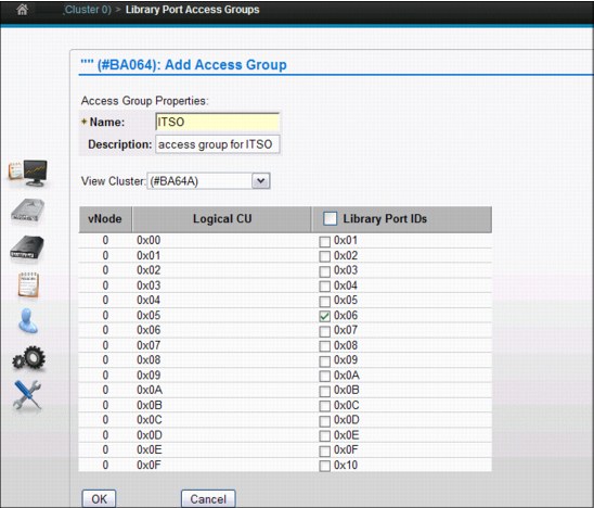
Figure 6-13 Add Access Group
Connecting volume ranges to access groups
After defining the access groups, the volume ranges need to be connected. You can define them to an existing access group.
Figure 6-14 on page 314 shows an example of defining volumes to the access group.
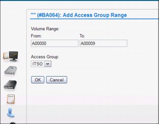
Figure 6-14 Defining a range of volumes to the access group
To assist in defining which existing volume ranges can be connected to the access groups, the MI window can assist you by showing all access groups and all existing volume ranges.
Figure 6-15 shows an example of the summary display listing all defined access groups.

Figure 6-15 Summary display listing all defined access groups
When you are out of logical volumes and need to insert more, you will see a warning message in the MI if the volumes are not fully covered by one or more existing ranges. This allows you to correct the range definition before the insert.
Secure access to define, update, or delete access groups
You can change whether a user can create, modify, or delete a library port access policy. But to ensure visibility, the properties option will always be available so a user can see the library port available in the policy. On the MI, you can define the access rules under Access → Roles and Permissions.
6.5 TS7700 SETTING function
The TS7700 Virtualization Engine SETTING function is part of the library Host Console Request function. The SETTING request provides information about many of the current workflow and management settings of the cluster specified in the request and the ability to modify the settings. It also allows alerts to be set for many of the resources managed by the cluster.
In response to the SETTING request, the composite library or the cluster associated with the distributed library in the request will modify its settings based on the additional keywords specified. If no additional keywords are specified, the request will just return the current settings.
With the SETTING function, you have the ability to modify the internal behavior of the TS7700 using the reporting standard setting. The TS7700 MI cannot be used for viewing or altering the parameters controlled by the SETTING function of the library Host Control Request function.
The following settings are available:
Alert settings If the ALERT keyword is specified, the cluster will set different thresholds at which a message is sent to all hosts attached to the cluster and, in a grid configuration, all hosts attached to all clusters. Additional keywords specify which alert threshold is to be set and the threshold value.
Cache settings If the keyword CACHE is specified, the cluster will modify how it controls the workflow and content of the TVC. Additional keywords specify which functions are enabled or disabled, or a value can be given.
Throttle settings If the keyword THROTTLE is specified, the cluster will modify how it controls the different data flow rates into and out of the cluster. Additional keywords specify which copy policy options are affected.
Reclaim settings If the keyword RECLAIM is specified, the cluster will modify how the reclaim background tasks control the workflow and content of the TVC. An additional keyword will specify the number of reclaim tasks.
Device Allocation settings If the keyword DEVALLOC is specified, the domain will modify how device allocation assistance (DAA) requests are handled. Additional keywords will enable or disable allocation preferences for scratch and private mounts.
Copy Thread Count settings If the keyword CPYCNT is specified, the domain will modify how many concurrent threads are allowed to process either RUN or DEFERRED copies. Additional keywords will set the number of copies for both types of copies.
Copy settings If the keyword COPY is specified, the cluster will modify the reporting method Immediate-deferred state. Additional keywords modify the volume copy timeout value.
Link settings If the keyword LINK is specified, the cluster will modify how to react in a link failover during a remote mount.
Delete Expire settings If the keyword DELXP is specified, the Delete Expire count will be modified.
All settings are persistent across machine restarts, service actions, and code updates. The settings are not carried forward as part of disaster recovery from copy-exported tapes or the recovery of a system.
A detailed description of the Host Console Request functions and responses is available in IBM Virtualization Engine TS7700 Series z/OS Host Command Line Request User’s Guide, which is available at the Techdocs website (search for the term TS7700):
Further detailed information is in 9.3.3, “Host Console Request function” on page 602. Information about performance aspects of the various parameters is in Chapter 10, “Performance and monitoring” on page 653.
6.6 Software implementation in z/VM and z/VSE
This section explains how to implement and run the TS7700 Virtualization Engine under z/VM and z/VSE. It covers the basics for software requirements, implementation, customization, and platform-specific considerations about operations and monitoring. For more detailed information, see IBM TS3500 Tape Library with System z Attachment A Practical Guide to Enterprise Tape Drives and TS3500 Tape Automation, SG24-6789.
6.6.1 General support information
Not all IBM Tape Libraries and TS7700 Virtualization Engine solutions are supported in all operating systems. Table 6-8 on page 317 shows a summary of several supported tape solutions for non-z/OS environments.
Table 6-8 Supported tape solutions for non-z/OS platforms in System z environments
|
Platform/Tape system
|
IBM System Storage TS3500 Tape Library
|
TS7700 Virtualization Engine
|
3592 drives
|
|
z/VM V5.4, V6.1, and V6.2 native
|
Yes
|
Yes1
|
Yes
|
|
z/VSE V4.3 native2
z/VSE V5.1 native3
|
Yes
|
Yes
|
Yes
|
|
z/VSE V4.3 under z/VMb
z/VSE V5.1 under z/VMc
|
Yes
|
Yesa
|
Yes
|
|
zTPF
|
Yes
|
Yes
|
Yes
|
1 With restrictions: See “Restrictions in all TS7700 Virtualization Engine environments” on page 317.
2 This platform includes support for Logical WORM (LWORM).
3 z/VSE V5.1 supports multicluster grid and Copy Export.
Even if z/VM and z/VSE can use the TS7700 Virtualization Engine, you must consider certain restrictions. For information about support for TPF, see 6.7, “Software implementation in Transaction Processing Facility” on page 323.
Restrictions in all TS7700 Virtualization Engine environments
z/VSE cannot provide SMS constructs to TS7700; however, clients might be able to take advantage of some of the Outboard policy management functions if they predefine the constructs to the logical volumes when they are entered through the MI. Another possibility is to use dedicated physical pools in a TS7700 Virtualization Engine environment. After the insert processing of virtual volumes completes, you can define a default construct to the volume range as described in 5.5, “Implementing Outboard Policy Management for non-z/OS hosts” on page 281.
TS7700 Virtualization Engine multicluster grid environments
z/VSE does not support TS7700 multicluster grid. z/VSE is unable to handle unsolicited messages and actions (for example, intervention-required and hardware messages). Therefore, a peer-to-peer VTS requires an active z/OS to support z/VSE. z/VSE 5.1 supports multicluster grid and Copy Export.
6.6.2 z/VM native support using DFSMS/VM
DFSMS/VM Function Level 221 (FL221) is the only way for a z/VM system to communicate with a TS7700 Virtualization Engine. DFSMS/VM FL221 is part of z/VM. The removable media services (RMS) function of DFSMS/VM FL221 provides TS7700 Virtualization Engine support in z/VM, as described in DFSMS/VM Function Level 221 Removable Media Services, SC24-6185.
Tape management
Although the RMS functions themselves do not include tape management system services, such as inventory management and label verification, RMS functions are designed to interface with a tape management system that can perform these functions. Additional information about third-party tape management systems that support the TS7700 Virtualization Engine in the z/VM environment is in IBM TotalStorage 3494 Tape Library: A Practical Guide to Tape Drives and Tape Automation, SG24-4632.
Figure 6-16 shows the z/VM native support for the TS7700 Virtualization Engine.
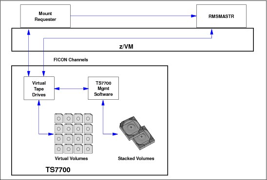
Figure 6-16 TS7700 Virtualization Engine in a native z/VM environment using DFSMS/VM
When you use the TS7700 Virtualization Engine in a VM environment, consider that many VM applications or system utilities use specific mounts for scratch volumes. So, every time a mount request is issued from the host, the TS7740 Virtualization Engine has to recall the requested logical volume from the stacked cartridge if it is not already in the TVC. This can lead to performance degradation when writing data in a VM environment. In addition, VM backups usually require offsite movement, so the TS7700 Virtualization Engine is not the best candidate for this data.
DFSMS/VM
After you define the new TS7700 Virtualization Engine Tape Library through HCD, you must define the TS7700 Virtualization Engine to DFSMS/VM if the VM system is to use the TS7700 Virtualization Engine directly. You define the TS7700 Virtualization Engine Tape Library through the DFSMS/VM DGTVCNTL DATA control file. Also, you define the available tape drives though the RMCONFIG DATA configuration file. See z/VM V6R2 DFSMS/VM Removable Media Services, SC24-6185, for more information.
You have access to RMS as a component of DFSMS/VM. To allow RMS to perform automatic insert bulk processing, you must create the RMBnnnnn data file in the VMSYS:DFSMS CONTROL directory, where nnnnn is the five-character tape library sequence number that is assigned to the TS7700 Virtualization Engine during hardware installation.
For details about implementing DFSMS/VM and RMS, see DFSMS/VM Function Level 221 Removable Media Services User’s Guide and Reference, SC35-0141. If the TS7700 Virtualization Engine is shared by your VM system and other systems, additional considerations apply. See Guide to Sharing and Partitioning IBM Tape Library Data, SG24-4409, for further information.
6.6.3 Native z/VSE
Native support is provided for the stand-alone grid TS7700 Virtualization Engine configuration in z/VSE Version 4.3 and later that support all IBM TS1130/TS1120/3592-J1A configurations (J70, C06, and TS7700 Virtualization Engine) without APARs in all automation offerings. This includes 3494 Enterprise Tape Library and TS3500 Tape Library configurations.
z/VSE supports the TS3500 Tape Library/3953 natively through its Tape Library Support (TLS). In addition to the old Tape Library Support, a function has been added to allow the Tape Library to be supported through the S/390 channel command interface commands, therefore eliminating any XPCC/APPC communication protocol required by the old interface. The external interface (LIBSERV JCL and LIBSERV macro) remains unchanged.
Define library support
First, define the type of support you are using by specifying the SYS ATL statement. You can define the following types:
TLS TLS Tape Library Support, which provides full VSE LPAR support
VSE LCDD, which does not support TS1130/TS1120/3592 (only IBM 3490E and 3590) and therefore not the TS3500 Tape Library
VM VM Guest Support, which when running z/VSE under z/VM and a TS7700 is used by both operating systems, where VSE Guest server (VGS) and DFSMS are needed (see 6.6.5, “z/VSE as a z/VM guest using a VSE Guest Server (VGS)” on page 321)
For native support under VSE, where TS7700 is used only by z/VSE, select TLS. At least one tape drive must be permanently assigned to VSE.
Define tape libraries
Next, define your tape library or libraries. This is done through a batch job as shown in Example 6-14. Use skeleton member TLSDEF from ICCF Lib 59.
Example 6-14 Define tape libraries
* $$ JOB JNM=TLSDEF,CLASS=0,DISP=D
* $$ LST CLASS=A
// JOB TLSDEF
// EXEC LIBR,PARM='MSHP'
ACCESS S=IJSYSRS.SYSLIB
CATALOG TLSDEF.PROC REPLACE=YES
LIBRARY_ID TAPELIB1 SCRDEF=SCRATCH00 INSERT=SCRATCH00 --- default library
LIBRARY_ID TAPELIB2 * SECOND LIB DEF
DEVICE_LIST TAPELIB1 460:463 * DRIVES 460 TO 463
DEVICE_LIST TAPELIB2 580:582 * DRIVES 580 TO 582
QUERY_INV_LISTS LIB=TLSINV * MASTER INVENTORY FILES
MANAGE_INV_LISTS LIB=TLSMAN * MANAGE FROM MASTER
/+
LIBSERV
The communication from the host to the TS7700 Virtualization Engine goes through the LIBSERV JCL or macro interface. Example 6-15 on page 320 shows a sample job using LIBSERV to mount volume 123456 for write on device address 480 and, in a second step, to release the drive again.
Example 6-15 Sample LIBSERV JCL
$$ JOB JNM=BACKUP,CLASS=0,DISP=D
$$ JOB BACKUP
// ASSGN SYS005,480
// LIBSERV MOUNT,UNIT=480,VOL=123456/W
// EXEC LIBR
BACKUP S=IJSYSRS.SYSLIB TAPE=480
/*
// LIBSERV RELEASE,UNIT=480
/&
$$ EOJ
LIBSERV provides the following functions:
Query all libraries for a volume LIBSERV AQUERY,VOL=123456
Mount from category LIBSERV CMOUNT,UNIT=480,SRCCAT=SCRATCH01
Mount a specific volume LIBSERV MOUNT,UNIT=480,VOL=123456
Demount a volume LIBSERV RELEASE,UNIT=480
Query count of volumes LIBSERV
CQUERY,LIB=TAPELIB1,SRCCAT= SCRATCH01
CQUERY,LIB=TAPELIB1,SRCCAT= SCRATCH01
Query device LIBSERV DQUERY,UNIT=480
Query inventory of library LIBSERV IQUERY,LIB=TAPELIB1,SRCCAT=SCRATCH01
Query library LIBSERV LQUERY,LIB=TAPELIB1
Manage inventory LIBSERV MINVENT,MEMNAME=ALL,TGTCAT=SCRATCH01
Change category LIBSERV SETVCAT,VOL=123456,TGTCAT=SCRATCH01
Query library for a volume LIBSERV SQUERY,VOL=123456,LIB=TAPELIB1
Copy Export LIBSERV COPYEX,VOL=123456,LIB=TAPELIB1
For additional information, see z/VSE System Administration Guide, SC33-8224, and z/VSE System Macros Reference, SC33-8230.
6.6.4 VM/ESA and z/VM guest support
This section describes two host environments that allow you to use an IBM TS7700 Virtualization Engine while running it as a guest host system under z/VM.
|
Tip: When z/OS is installed as a z/VM guest on a virtual machine, you must specify the following statement in the virtual machine directory entry for the VM user ID under which the z/OS guest operating system is IPLed:
STDEVOPT LIBRARY CTL
|
z/OS guests
The environments described in 6.3.1, “z/OS and DFSMS/MVS system-managed tape” on page 308 can operate when z/OS is running as a guest of z/VM Release 5.4 or later.
In this environment, additional software products are not required.
The STDEVOPT statement specifies the optional storage device management functions available to a virtual machine. The LIBRARY operand with CTL tells the control program that the virtual machine is authorized to issue tape library commands to an IBM Automated Tape Library Dataserver. If the CTL parameter is not explicitly coded, the default of NOCTL is used. NOCTL specifies that the virtual machine is not authorized to issue commands to a tape library, and this results in an I/O error (command reject) when MVS tries to issue a command to the library. For further information about the STDEVOPT statement, go to the following address:
z/VSE guests
Some VSE tape management systems require VSE Guest Server (VGS) support and also DFSMS/VM RMS for communication with the TS7700 Virtualization Engine.
If the VGS is required, define the LIBCONFIG file and FSMRMVGC EXEC configuration file on the VGS service machine’s A disk. This file simply cross-references the z/VSE guest’s tape library names with the names that DFSMS/VM uses. To enable z/VSE guest exploitation of inventory support functions through the LIBSERV-VGS interface, the LIBRCMS part must be installed on the VM system.
If VGS is to service inventory requests for multiple z/VSE guests, you must edit the LIBRCMS SRVNAMES cross-reference file. This file enables the inventory support server to access Librarian files on the correct VSE guest machine. For more information, see 6.6.5, “z/VSE as a z/VM guest using a VSE Guest Server (VGS)” on page 321 and 7.6, “VSE Guest Server Considerations” in Guide to Sharing and Partitioning IBM Tape Library Data, SG24-4409.
CA DYNAM/TM-VSE does not use the VGS machine.
6.6.5 z/VSE as a z/VM guest using a VSE Guest Server (VGS)
When a z/VSE guest machine uses a tape drive in the TS7700 Virtualization Engine, the virtual tape drive must be attached to that machine and the virtual tape volume must be mounted on the drive. Because, as a virtual machine, z/VSE cannot communicate with the TS7700 Virtualization Engine to request a tape mount, RMSMASTR (a z/VM machine) must attach the tape drive and mount the volume. However, z/VSE cannot use RMSMASTR directly, because RMS functions run only in CMS mode.
Therefore, some z/VSE guest scenarios use the CMS service machine, called the VGS, to communicate with RMSMASTR. VGS uses the standard facilities of RMS to interact with the TS7700 Virtualization Engine and the virtual drives.
Figure 6-17 shows the flow and connections of a TS7700 Virtualization Engine in a z/VSE environment under VM.

Figure 6-17 TS7700 Virtualization Engine in a z/VSE environment as a VM guest
Tape management systems
As with the IBM VM/ESA native environment (see 6.6.2, “z/VM native support using DFSMS/VM” on page 317), the tape management system is responsible for keeping an inventory of volumes in the TS7700 Virtualization Engine that belong to z/VSE. Some vendor tape management support scenarios do not use VGS. Instead, they communicate directly with RMSMASTR through CSL calls.
Figure 6-18 shows CA-DYNAM/T VSE.

Figure 6-18 TS7700 Virtualization Engine in a z/VSE environment as a VM guest (no VGS)
VSE uses other equipment manufacturer (OEM) tape management products that support scratch mounts. So, if you are using VSE under VM, you have the benefit of using the scratch (Fast Ready) attribute for the VSE library’s scratch category.
For more information about z/VSE, see z/VSE V4R3.0 Administration, SC33-8304, and z/VSE V5R1.0 Administration, SC34-2627.
6.7 Software implementation in Transaction Processing Facility
This section describes the support for a TS7700 Virtualization Engine in a native Transaction Processing Facility (TPF) environment with TPF V4.1 or z/TPF. The TPF control program and several new and modified TPF E-type programs support the TS7740 Virtualization Engine and TS7720 Virtualization Engine. The support is limited to a command-based interface.
Because TPF does not have a tape management system or a tape catalog system, z/OS manages this function. In a TPF environment, most tape data is passed between the systems. In general, 90% of the tapes are created on TPF and read on z/OS, and the remaining 10% are created on z/OS and read on TPF.
Be sure to use the normal z/OS and TS7700 Virtualization Engine installation processes.
6.7.1 Usage considerations for TS7700 with TPF
TPF uses virtual volumes from the z/OS scratch pools and shares the TS7700 Virtualization Engine scratch categories with z/OS. The z/OS host performs the insert processing for these virtual volumes and continues to manage them based on the input obtained from TPF. TPF has a set of commands (ztplf), which you use to load the volumes in TPF-allocated virtual drives.
After a volume is loaded into a TPF drive, you have an automated solution in place that passes the volume serial number (VOLSER), the tape data set name, and the expiration date over to z/OS to process it automatically.
On z/OS, you must update the tape management system’s catalog and the TCDB so that z/OS can process virtual volumes that have been created by TPF. After the TPF-written volumes have been added to the z/OS tape management system catalog and the TCDB, normal expiration processing applies. When the data on a virtual volume has expired and the volume is returned to scratch, the TS7700 Virtualization Engine internal database is updated to reflect the volume information maintained by z/OS.
Specifics for TPF and z/OS with a shared TS7700 Virtualization Engine
From the virtual drive side, TPF must be allocated certain drive addresses. This information depends on the tape functions that are needed on TPF, and can vary with your set. Therefore, the TS7700 Virtualization Engine will have tape addresses allocated to multiple TPF and z/OS systems, and can be shared by dedicating device addresses to other systems.
Tapes that are created on z/OS and read into TPF
Tapes that are created on z/OS and read into TPF use the same z/OS process for creating tapes. Now, when TPF wants to read this z/OS-created tape, it does a specific mount of the tape virtual server network (VSN) into a TPF-allocated drive using the TPF (ztplf) commands.
TS7700 Virtualization Engine performance for TPF
You can use the normal TPF Data Collection and Reduction reports that summarize read and write activity to the TPF-allocated drive. For TS7700 Virtualization Engine-specific performance, use the normal TS7700 Virtualization Engine statistics that are offloaded to z/OS through the TS7700 Virtualization Engine Bulk Volume Information Retrieval (BVIR) function.
Support of large virtual volumes for TPF (2 GB and 4 GB)
TPF itself does not use functions, such as Data Class, to control the logical volume size for specific mounts. User exits provide the ability to set construct names for a volume. If you are not using the user exits, you can set the default size through the TS7700 Virtualization Engine management interface during logical volume insertion, as described in 5.5, “Implementing Outboard Policy Management for non-z/OS hosts” on page 281.
Consider the following information when you implement a TS7700 Virtualization Engine in a TPF environment:
•Reserving a tape category does not prevent another host from using that category. You are responsible for monitoring the use of reserved categories.
•Automatic insert processing is not provided in TPF.
•Currently, no IBM tape management system is available for TPF.
Advanced Policy Management is supported in TPF through a user exit. The exit is called any time a volume is loaded into a drive. At that time, the user can specify, through the TPF user exit, whether the volume will inherit the attributes of an existing volume using the clone VOLSER attribute. Or, the code can elect to specifically set any or all of the Storage Group, Management Class, Storage Class, or Data Class construct names. If the exit is not coded, the volume attributes remain unchanged because the volume is used by TPF.
For the two levels of TPF, two separate APARs are required for this support:
•For TPF V4.1, the APAR number is PJ31643.
•For zTPFV 1.1, the APAR number is PJ31394.
Library interface
TPF’s only operator interface to the TS7700 Virtualization Engine is a TPF functional message, ZTPLF. The various ZTPLF functions allow the operator to manipulate the tapes in the library as operational procedures require. These functions include Reserve, Release, Move, Query, Load, Unload, and Fill. For more information, see IBM TotalStorage 3494 Tape Library: A Practical Guide to Tape Drives and Tape Automation, SG24-4632.
Control data sets
The TPF host does not keep a record of the volumes in the TS7700 Virtualization Engine Tape Library or manage the tape volumes in it. You can use the QUERY command to obtain information about the tape volumes held in the TS3500/3952 Tape Library.
Service information message and media information message presentation
Service information messages (SIMs) and media information messages (MIMs) report hardware-related problems to the operating system.
SIMs and MIMs are represented in TPF by environmental recording, editing, and printing (EREP) reports and the following messages:
•CEFR0354
•CEFR0355W
•CEFR0356W
•CEFR0357E
•CEFR0347W
•CDFR0348W
•CDFR0349E
6.7.2 Performance considerations for TS7700 multicluster grids with TPF
When clusters are operating within a TS7700 grid, they share information about the status of volumes and devices. Certain operations initiated by TPF require all the clusters in the grid to communicate with one another. Under normal conditions, this communication occurs without delay and no impact to TPF. In addition, if one cluster has failed and the other clusters in the grid have recognized that condition, the communication with that cluster is no longer needed.
The issue with TPF arises when the period that clusters wait before recognizing that another cluster in the grid has failed exceeds the timeout values on TPF. This issue also means that during this recovery period, TPF is unable to perform any ZTPLF commands that change the status of a volume, including loading tapes or changing the category of a volume through a ZTPLF command or through the tape category user exit in segment CORU. The recovery period when a response is still required from a failing cluster can be as long as six minutes. Attempting to issue a tape library command to any device in the grid during this period can render that device inoperable until the recovery period has elapsed even if the device is on a cluster that is not failing.
To protect against timeouts during a cluster failure, TPF systems must be configured to avoid issuing tape library commands to devices in a TS7700 grid along critical code paths within TPF. This can be accomplished through the tape category change user exit in the segment CORU. To isolate TPF from timing issues, the category for a volume must not be changed if the exit has been called for a tape switch. Be sure that the exit changes the category when a volume is first loaded by TPF and then not changed again.
To further protect TPF against periods in which a cluster is failing, TPF must keep enough volumes loaded on drives that have been varied on to TPF so that the TPF system can operate without the need to load an additional volume on any drive in the grid until the cluster failure has been recognized. TPF must have enough volumes loaded so that it can survive the six-minute period where a failing cluster prevents other devices in that grid from loading any new volumes.
|
Important: Read and write operations to devices in a grid do not require communication between all clusters in the grid. Eliminating the tape library commands from the critical paths in TPF helps TPF tolerate the recovery times of the TS7700 and read or write data without problems if a failure of one cluster occurs within the grid.
|
Another configuration consideration relates to volume ownership. Each volume in a TS7700 grid is owned by one of the clusters in the grid. When a scratch volume is requested from a category for a specific device, a volume that is owned by the cluster to which that device belongs is selected, if possible. TPF systems must always be configured so that any scratch category is populated with volumes that are owned by each cluster in the grid. In this manner, TPF will have access to a scratch tape that is owned by the cluster that was given the request for a scratch volume. If all the volumes in a grid are owned by one cluster, a failure on that cluster will require a cluster takeover (which can take tens of minutes) before volume ownership can be transferred to a surviving cluster.
Guidelines
When TPF applications use a TS7700 multicluster grid represented by the composite library, the following usage and configuration guidelines can help you meet the TPF response-time expectations on the storage subsystems:
•The best configuration is to have the active and standby TPF devices and volumes on separate composite libraries (either single-cluster or multicluster grid). This configuration prevents a single event on a composite library from affecting both the primary and secondary devices.
•If the active and standby TPF devices/volumes will be configured on the same composite library in a grid configuration, be sure to use the following guidelines:
– Change the category on a mounted volume only when it is first mounted through the ZTPLF LOAD command or as the result of a previous ZTPLF FILL command.
This change can be accomplished through the tape category change user exit in the segment CORU. To isolate TPF from timing issues, the category for a volume must never be changed if the exit has been called for a tape switch. Be sure that the exit changes the category when a volume is first loaded by TPF, and then not changed again.
– TPF must keep enough volumes loaded on drives that have been varied on to TPF so that the TPF system can operate without the need to load additional volumes on any drive in the grid until a cluster failure has been recognized and the cluster isolated. TPF must have enough volumes loaded so that it can survive the six-minute period when a failing cluster prevents other devices in that grid from loading any new volumes.
– TPF systems must always be configured so that any scratch category is made up of volumes that are owned throughout all the various clusters in the grid. This method assures that during cluster failures, volumes on other clusters are available for use without having ownership transfers.
•Only use the RUN Copy Consistency Point for the cluster that will be used as the TVC. All other clusters must be configured with the Deferred consistency point to avoid timeouts on the close of the volume.
..................Content has been hidden....................
You can't read the all page of ebook, please click here login for view all page.