

Hardware implementation
This chapter describes the hardware-related implementation steps for the IBM Virtualization Engine TS7700.
It covers all implementation steps that relate to the setup of the following products:
•IBM System Storage TS3500 Tape Library
•TS7700 Virtualization Engine
|
Important: IBM 3494 Tape Library attachment is not supported at Release 2.0 and later.
|
For information about host software implementation, see Chapter 6, “Software implementation” on page 285 that describes the hardware configuration definition (HCD) steps on the host and operating system-related definitions.
This chapter includes the following sections:
5.1 TS7700 Virtualization Engine implementation and installation considerations
The following sections discuss the implementation and installation tasks to set up the TS7700 Virtualization Engine. The TS7700 Virtualization Engine includes both the IBM Virtualization Engine TS7720 and the IBM Virtualization Engine TS7740, so specific names are used in this chapter if a certain task only applies to one of the two because there are slight differences between the TS7720 Virtualization Engine and the TS7740 Virtualization Engine.
The TS7720 Virtualization Engine does not have a tape library attached, so the implementation steps related to a physical tape library, TS3500 Tape Library, do not apply to the TS7720 Virtualization Engine.
You can install the TS7740 Virtualization Engine together with your existing TS3500 Tape Library. Because the Library Manager functions reside inside of TS7700 Virtualization Engine microcode, the TS7740 itself manages all necessary operations, so the IBM 3953 Tape System is no longer required to attach a TS7740 Virtualization Engine.
|
Important: System z attachment of native 3592 tape drives through a tape controller might still require the IBM 3953 Tape System. See IBM TS3500 Tape Library with System z Attachment A Practical Guide to Enterprise Tape Drives and TS3500 Tape Automation, SG24-6789, for more information.
|
You can also install a new TS3500 Tape Library and a new TS7740 Virtualization Engine at the same time.
5.1.1 Implementation tasks
The TS7700 Virtualization Engine implementation can be logically separated into three major sections:
•TS7740 Virtualization Engine and tape library setup
Use the TS7740 Virtualization Engine and the TS3500 Tape Library interfaces for these setup steps:
– Defining the logical library definitions of the TS7740 Virtualization Engine, such as physical tape drives and cartridges, using the TS3500 Tape Library Specialist, which is the web browser interface to the TS3500 Tape Library.
– Defining specific settings, such as encryption, and inserting logical volumes into the TS7740 Virtualization Engine. You can also use the management interface (MI) to define logical volumes, management policies, and volume categories.
This chapter provides details of these implementation steps.
•TS7700 Hardware I/O configuration definition
This section relates to the system generation. It consists of processes, such as FICON channel attachment to the host, HCD/input/output configuration program (IOCP) definitions, and Missing Interrupt Handler (MIH) settings. This activity can be done before the physical hardware installation and it can be part of the preinstallation planning.
These installation steps are described in Chapter 6, “Software implementation” on page 285.
•TS7700 Virtualization Engine software definition
This is where you define the new virtual tape library to the individual host operating system. In a System z environment with Data Facility Storage Management Subsystem (DFSMS)/IBM MVS, this includes updating DFSMS automatic class selection (ACS) routines, object access method (OAM), and your tape management system during this phase. You also define Data Class (DC), Management Class (MC), Storage Class (SC), and Storage Group (SG) constructs and selection policies, which are passed to the TS7700 Virtualization Engine.
These installation steps are described in Chapter 6, “Software implementation” on page 285.
These three groups of implementation tasks can be done in parallel or sequentially. HCD and host definitions can be completed before or after the actual hardware installation.
5.1.2 Installation tasks
The tasks outlined in this section are specific to the simultaneous installation of a TS3500 Tape Library and a TS7740 Virtualization Engine.
|
Important: IBM 3494 Tape Library attachment is not supported at Release 2.0 and later.
|
If you are installing a TS7740 Virtualization Engine in an existing TS3500 Tape Library environment, some of these tasks might not apply to you:
•Hardware-related activities (completed by your IBM System Service Representative (SSR)):
– Install the IBM TS3500 Tape Library.
– Install any native drives that will not be controlled by the TS7740 Virtualization Engine.
– Install the TS7740 Virtualization Engine Frame and additional D2x frame or frames in the TS3500 Tape Library.
•Define drives to hosts:
– z/OS
– z/VM
– z/VSE
– TPF and z/TPF
•Software-related activities:
– Apply maintenance for the TS3500 Tape Library.
– Apply maintenance for the TS7700 Virtualization Engine.
– Verify or update exits for the tape management system (if applicable) and define logical volumes to it.
– See z/VM V5R4.0 DFSMS/VM Removable Media Services, SC24-6090, and 6.6, “Software implementation in z/VM and z/VSE” on page 316.
•Specific TS7700 Virtualization Engine activities:
– Define policies and constructs using the TS7700 Virtualization Engine MI.
– Define the logical VOLSER ranges of the logical volumes through the TS7700 Virtualization Engine MI.
•Specific TS7740 Virtualization Engine installation activities:
– Define the TS7740 Virtualization Engine environment using the TS3500 Tape Library Specialist.
– Define pool properties.
– Define the physical VOLSER ranges for TS7740 Virtualization Engine-owned physical volumes to the MI of the TS7740 Virtualization Engine and TS3500 Tape Library (if applicable).
– Insert TS7740 Virtualization Engine-owned physical volumes in the tape library.
•If you will use encryption, you must specify the system-managed encryption method in the TS3500 web MI, and set all drives for the logical library as Encryption Capable.
|
Important: Encryption does not work with tape drives in emulation mode. Tape drives must be set to Native mode.
|
These tasks are further described, including the suggested order of events, later in this chapter.
After your TS7740 Virtualization Engine is installed on the TS3500 Tape Library, perform the following post-installation tasks:
•Schedule and complete operator training.
•Schedule and complete storage administrator training.
5.2 TS3500 Tape Library definitions (TS7740 Virtualization Engine)
Use this section if you are implementing the TS7740 Virtualization Engine in a TS3500 Tape Library in a System z environment. If your TS7700 Virtualization Engine does not have an associated tape library (TS7720), see 5.3, “Setting up the TS7700 Virtualization Engine” on page 212.
Your IBM SSR performs the hardware installation of the TS7740 Virtualization Engine, its associated tape library, and the frames. This installation does not require your involvement other than the appropriate planning. See Chapter 4, “Preinstallation planning and sizing” on page 123 for details.
The following topics are covered in this section:
•Defining a logical library
•Cartridge assignment policies
•Eight-character VOLSER support
•Assigning drives and creating control paths
•Defining an encryption method and encryption-capable drives
After the SSR has physically installed the library hardware, you can use the TS3500 Tape Library Specialist to set up the logical library, which is attached to the System z host.
|
Clarification: The steps described in the following section relate to the installation of a new IBM TS3500 Tape Library with all the required features, such as ALMS, already installed. If you are attaching an existing IBM TS3500 Tape Library that is already attached to Open Systems hosts to System z hosts also, see IBM TS3500 Tape Library with System z Attachment A Practical Guide to Enterprise Tape Drives and TS3500 Tape Automation, SG24-6789, for additional actions that might be required.
|
5.2.1 Defining a logical library
The TS3500 Tape Library Specialist is required to define a logical library and perform the following tasks. Therefore, ensure that it is set up properly and working. For access through a standard-based web browser, an IP address must be configured, which will be done initially by the SSR during the hardware installation at the TS3500 Tape Library operator window.
|
Important:
•Each TS7740 Virtualization Engine requires its own logical library in a TS3500 Tape Library.
•The ALMS feature must be installed and enabled to define a logical library partition in the TS3500 Tape Library.
|
Ensure that ALMS is enabled
Before enabling ALMS, the ALMS license key has to be entered through the TS3500 Tape Library Operator window, because ALMS is a chargeable feature.
You can check the status of ALMS with the TS3500 Tape Library Specialist by selecting Library → ALMS, as shown in Figure 5-1.

Figure 5-1 TS3500 Tape Library Specialist System Summary and Advanced Library Management System windows
As you can see in the ALMS window (at the bottom of the picture), ALMS is enabled for this TS3500 Tape Library.
When ALMS is enabled for the first time in a partitioned TS3500 Tape Library, the contents of each partition will be migrated to ALMS logical libraries. When enabling ALMS in a non-partitioned TS3500 Tape Library, cartridges that already reside in the library are migrated to the new ALMS single logical library.
Creating a new logical library with ALMS
This function is valid and available only if ALMS is enabled.
|
Tip: You can create or remove a logical library from the TS3500 Tape Library by using the Tape Library Specialist web interface.
|
1. From the main section of the TS3500 Tape Library Specialist Welcome window, go to the work items on the left side of the window and select Library → Logical Libraries, as shown in Figure 5-2.
2. From the Select Action drop-down menu, select Create and click Go.
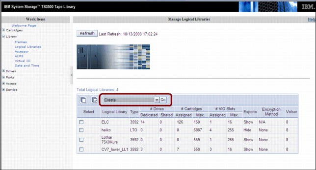
Figure 5-2 Create logical library starting window
An additional window, named Create Logical Library, opens. Both windows are shown in Figure 5-3.
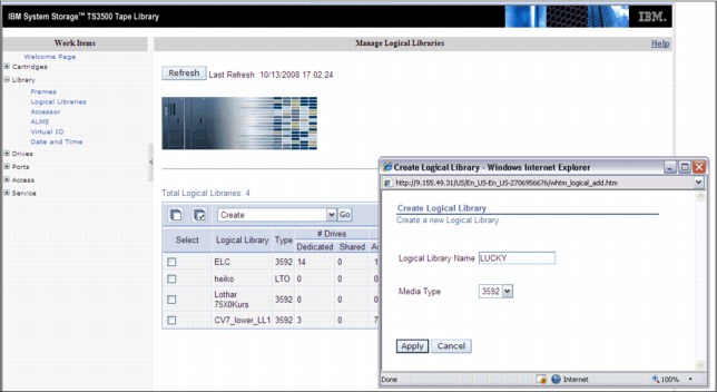
Figure 5-3 Create Logical Library windows
3. Type the logical library name (up to 15 characters), select the media type (3592 for TS7740), and then click Apply. The new logical library is created and displays in the logical library list when the window is refreshed.
After the logical library is created, you can display its characteristics by selecting Library → Logical Libraries under work items on the left side of the window, as shown in Figure 5-4 on page 197. From the Select Action drop-down menu, select Details and then click Go.
In the Logical Library Details window, you see the element address range. The starting element address of each newly created logical library starts one element higher, such as the following examples:
•Logical Library 1: Starting SCSI element address is 1025.
•Logical Library 2: Starting SCSI element address is 1026.
•Logical Library 3: Starting SCSI element address is 1027.
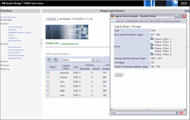
Figure 5-4 Recording of the starting SCSI element address of a logical library
Setting the maximum cartridges for the logical library
Define the maximum number of cartridge slots for the new logical library. If multiple logical libraries are defined, you can define the maximum number of tape library cartridge slots for each logical library. This allows a logical library to grow without a reconfiguration each time you want to add empty slots. To define the quantity of cartridge slots, select a new logical library from the list, and from drop-down menu, select Maximum Cartridges and then click Go.
Figure 5-5 shows the web interface windows.

Figure 5-5 Defining the maximum number of cartridges
Setting eight-character Volser option in the new logical library
Check the new logical library for the eight-character Volser reporting option. Go to the Manage Logical Libraries window under Library in the Tape Library Web Specialist, as shown in Figure 5-6.

Figure 5-6 Check Volser reporting option
If the new logical library does not show 8 in the Volser column, correct the information:
1. Select a logical library.
2. Click the Select Action drop-down menu and select Modify Volser Reporting.
3. Click Go.
Figure 5-7 illustrates the sequence.

Figure 5-7 Modifying Volser Reporting length
4. In the pop-up window, select the correct Volser character length, which is 8 (default), and apply it as shown in Figure 5-8.

Figure 5-8 Setting 8-character Volser
5.2.2 Adding drives to the logical library
From the Logical Libraries window shown in Figure 5-4 on page 197, use the work items on the left side of the window to navigate to the requested web page by selecting Drives → Drive Assignment.
|
Restriction: No intermix of tape drive models is supported by TS7740 with the only exception of the 3592-E05 Tape Drives working in J1A emulation mode and 3592-J1A Tape Drives (those were the first and second generation of the 3592 Tape Drives).
TS1130 (3592 Model E06) and TS1140 (3592 Model E07) cannot be intermixed with any other model of 3592 Tape Drive within the same TS7740.
|
This link takes you to a filtering window where you can select to have the drives displayed by drive element or by logical library. Upon your selection, a window opens so that you can add a drive to or remove a drive from a library configuration. It also enables you to share a drive between Logical Libraries and define its drive as a control path.
|
Restriction: Do not share drives belonging to a TS7740 (or any other control unit). They must be exclusive.
|
Figure 5-9 on page 201 shows the drive assignment window of a logical library that has all drives assigned.
Unassigned drives appear in the Unassigned column with the box checked, so to assign them, check the appropriate drive box under the logical library name and click Apply.
Click the Help link at the upper-right corner of the window, shown in Figure 5-9, to see extended help information, such as detailed explanations of all the fields and functions of the window. The other TS3500 Tape Library Specialist windows provide similar help support.

Figure 5-9 Drive Assignment window
In a multi-platform environment, you see logical libraries as shown in Figure 5-9, and you can reassign physical tape drives from one logical library to another. You can easily do this for the Open Systems environment, where the tape drives attach directly to the host systems without a tape controller or VTS/TS7700 Virtualization Engine.
|
Restriction: Do not change drive assignments if they belong to an operating TS7740 or tape controller. Work with your IBM SSR, if necessary.
|
In a System z environment, a tape drive always attaches to one tape control unit or TS7740 Virtualization Engine only. If you reassign a tape drive from a TS7740 Virtualization Engine or an IBM 3953 Library Manager partition to an Open Systems partition temporarily, you must also physically detach the tape drive from the TS7740 Virtualization Engine or tape controller first, and then attach the tape drive to the Open Systems host. Ensure that only IBM SSRs perform these tasks to protect your tape operation from unplanned outages.
|
Important: In a System z environment, use the Drive Assignment window only for these functions:
•Initially assign the tape drives from TS3500 Tape Library Web Specialist to a logical partition.
•Assign additional tape drives after they have been attached to the TS7740 Virtualization Engine or a tape controller.
•Remove physical tape drives from the configuration after they are physically detached from the TS7740 Virtualization Engine or tape controller.
In addition, never disable ALMS at the TS3500 Tape Library after it has been enabled for System z host support and System z tape drive attachment.
|
5.2.3 Defining control path drives
Each TS7740 Virtualization Engine requires four control path drives defined. If possible, distribute the control path drives over more than one TS3500 Tape Library frame to avoid single points of failure.
In a logical library, you can designate any dedicated drive to become a control path drive. A drive that is loaded with a cartridge cannot become a control path until you remove the cartridge. Similarly, any drive that is a control path cannot be disabled until you remove the cartridge that it contains.
The definition of the control path drive is specified on the Drive Assignment window shown in Figure 5-10. Notice that drives, defined as control paths, are identified by the symbol on the left side of the drive box. You can change the control path drive definition by selecting or deselecting this symbol.

Figure 5-10 Control Path symbol
5.2.4 Defining the Encryption Method for the new logical library
After adding tape drives to the new logical library, you must specify the Encryption Method for the new logical library (if applicable).
|
Reminders:
•When using encryption, tape drives must be set to Native mode.
•To activate encryption, FC9900 must have been ordered for the TS7400 and the license key factory must be installed. Also, the associated tape drives must be Encryption Capable 3592-E05, 3592-E06, or 3952-E07 (although supported, 3592-J1A is unable to encrypt data).
|
Perform the following steps:
1. Check the drive mode by opening the Drives summary window in the TS3500 MI, as shown in Figure 5-11 on page 203, and look in the Mode column. This column is displayed only if drives in the tape library are emulation-capable.

Figure 5-11 Drive mode
2. If necessary, change the drive mode to Native mode. In the Drives summary window, select a drive and select Change Emulation Mode, as shown in Figure 5-12.

Figure 5-12 Changing drive emulation
3. In the next window that opens, select the native mode for the drive. After the drives are at the desired mode, proceed with the Encryption Method definition.
4. In the TS3500 MI, select Library → Logical Libraries, select the logical library with which you are working, select Modify Encryption Method, and then click Go. See Figure 5-13.

Figure 5-13 Selecting the Encryption Method
5. In the window that opens, select System-Managed for the chosen method, and select all drives for this partition. See Figure 5-14.

Figure 5-14 Setting the Encryption Method
To make encryption fully operational in the TS7740 configuration, additional steps are necessary. Work with your IBM SSR to configure the Encryption parameters in the TS7740 during the installation process.
|
Important: Keep the Advanced Encryption Settings as NO ADVANCED SETTING, unless specifically set otherwise by IBM Engineering.
|
5.2.5 Defining Cartridge Assignment Policies
The Cartridge Assignment Policy (CAP) of the TS3500 Tape Library is where you can assign ranges of physical cartridge volume serial numbers to specific logical libraries. If you have previously established a CAP and place a cartridge with a VOLSER that matches that range into the I/O station, the library automatically assigns that cartridge to the appropriate logical library.
Select Cartridge Assignment Policy from the Cartridges work items to add, change, and remove policies. The maximum quantity of Cartridge Assignment Policies for the entire TS3500 Tape Library must not exceed 300.
Figure 5-15 shows the VOLSER ranges defined for logical libraries.

Figure 5-15 TS3500 Tape Library Cartridge Assignment Policy
The TS3500 Tape Library allows duplicate VOLSER ranges for different media types only. For example, Logical Library 1 and Logical Library 2 contain Linear Tape-Open (LTO) media, and Logical Library 3 contains IBM 3592 media. Logical Library 1 has a Cartridge Assignment Policy of ABC100-ABC200. The library will reject an attempt to add a Cartridge Assignment Policy of ABC000-ABC300 to Logical Library 2 because the media type is the same (both LTO). However, the library does allow an attempt to add a Cartridge Assignment Policy of ABC000-ABC300 to Logical Library 3 because the media (3592) is different.
In a storage management subsystem (SMS)-managed z/OS environment, all VOLSER identifiers across all storage hierarchies are required to be unique. Follow the same rules across host platforms also, whether or not you are sharing a TS3500 Tape Library between System z and Open Systems hosts.
|
Tip: The Cartridge Assignment Policy does not reassign an already assigned tape cartridge. If needed, you must first make it unassigned, and then manually reassign it.
|
5.2.6 Inserting TS7740 Virtualization Engine physical volumes
The TS7740 Virtualization Engine subsystem manages both logical and physical volumes. The Cartridge Assignment Policy (CAP) of the TS3500 Tape Library only affects the physical volumes associated with this TS7740 Virtualization Engine logical library. Logical Volumes are managed from the TS7700 Virtualization Engine MI only.
Perform the following steps to add physical cartridges:
1. Define Cartridge Assignment Policies at the TS3500 Tape Library level by using ALMS through the Web Specialist. This ensures that all TS7740 Virtualization Engine ranges are recognized and assigned to the correct TS3500 Tape Library logical library partition (the logical library created for this specific TS7740 Virtualization Engine) before you begin any TS7700 Virtualization Engine MI definitions.
2. Physically insert volumes into the library by using the I/O station or by opening the library and placing cartridges in empty storage cells. Cartridges are assigned to the TS7740 logical library partitions according to the definitions.
|
Important: Before inserting TS7740 Virtualization Engine physical volumes into the tape library, ensure that the VOLSER ranges are defined correctly at the TS7740 MI. See 5.3.3, “Defining VOLSER ranges for physical volumes” on page 215.
|
These procedures ensure that TS7700 Virtualization Engine back-end cartridges will never be assigned to a host by accident. Figure 5-16 shows the flow of physical cartridge insertion and assignment to logical libraries for TS7740 Virtualization Engine.

Figure 5-16 Volume assignment
Inserting physical volumes into the TS3500 Tape Library
Two methods are available for inserting physical volumes into the TS3500 Tape Library:
•Opening the library doors and inserting the volumes directly into the tape library storage empty cells (bulk loading)
•Using the TS3500 Tape Library I/O station
Insertion directly into storage cells
Use the operator window of the TS3500 to pause it. Open the door and insert the cartridges into any empty slot, except those slots reserved for diagnostic cartridges, which are Frame 1, Column 1 in the first Row (F01, C01, and R01) in a single media-type library.
|
Important: With ALMS enabled, cartridges that are not in a CAP will not be added to any logical library.
|
After completing the new media insertion, close the doors. After approximately 15 seconds, the TS3500 automatically inventories the frame or frames of the door you opened. During the inventory, the message INITIALIZING is displayed on the Activity window on the operator window. When the inventory completes, the TS3500 operator window displays a Ready state. The TS7740 Virtualization Engine uploads its logical library inventory and updates its Integrated Library Manager inventory accordingly. After completing this operation, the TS7740 Virtualization Engine Library reaches the Auto state.
Place cartridges only in a frame that has an open front door. Do not add or remove cartridges from an adjacent frame.
Insertion by using the I/O station
With the ALMS, your TS3500 can be operating with or without virtual I/O being enabled. The procedure varies depending on which mode is active in the library.
Basically, with virtual I/O (VIO) enabled, TS3500 will move the cartridges from the physical I/O station into the physical library by itself. In the first moment, the cartridge leaves the physical I/O station and goes into a slot mapped as a virtual I/O - SCSI element between 769 (X’301’) and 1023 (X’3FF’) for the logical library selected by the CAP.
Each logical library has its own set of up to 256 VIO slots. This is defined in the logical library creation, and can be altered later, if needed.
With VIO disabled, the TS3584 does not move cartridges from the physical I/O station unless it receives a command from the TS7400 Virtualization Engine or any other controlling host.
In both cases, the TS3500 detects the volumes inserted when the I/O station door is closed and scans all I/O cells using the bar code reader. The CAP decides to which logical library those cartridges belong and then performs one of the following tasks:
•Moves them to that logical library’s virtual I/O slots, if VIO is enabled.
•Waits for a host command in this logical partition. The cartridges stay in the I/O station after the bar code scan.
Because the inserted cartridges belong to a defined range in the CAP of this logical library, and those ranges were defined in the TS7740 Virtualization Engine Physical Volume Range as explained in 5.3.3, “Defining VOLSER ranges for physical volumes” on page 215, those cartridges will be assigned to this logical library. If any VOLSER is not in the range defined by the CAP, the operator must identify the correct logical library as the destination by using the Insert Notification window at the operator window. If Insert Notification is not answered, the volume remains unassigned.
|
Restriction: Insert Notification is not supported on a high-density library. If a cartridge outside the CAP-defined ranges is inserted, it will remain unassigned without any notification.
|
Verify that the cartridges were correctly assigned by using the TS3500 MI. Click Cartridges → Data Cartridges and select the appropriate logical library. If everything is correct, the inserted cartridges will be listed. Alternatively, displaying the Unassigned/Shared volumes show none. See Figure 5-17.
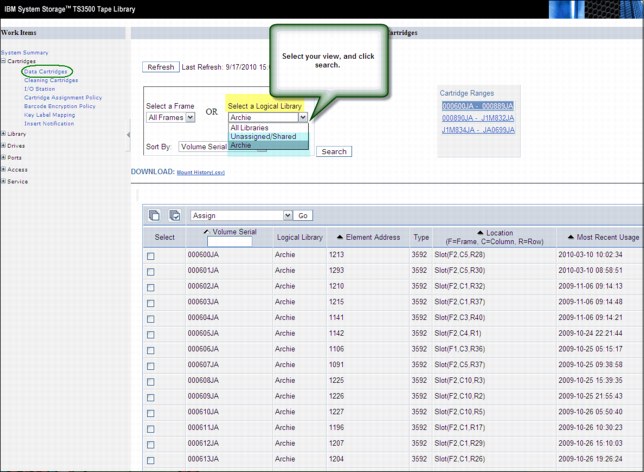
Figure 5-17 Checking volume assignment
Unassigned volumes in the TS3500 Tape Library
If a volume does not match the definitions in the CAP and if during the Insert Notification process, no owner was specified, the cartridge remains unassigned in the TS3500 Tape Library. You can check for unassigned cartridges by using the TS3500 MI and selecting Cartridges → Data Cartridges. In the drop-down menu, select Unassigned/Shared (Figure 5-17).
You can then assign the cartridges to the TS7740 Virtualization Engine logical library partition by following the procedure in 5.2.7, “Assigning cartridges in the TS3500 Tape Library to the logical library partition” on page 210.
|
Important: Unassigned cartridges can exist in the TS3500 Tape Library, and in the TS7700 Virtualization Engine MI. But “unassigned” has separate meanings and requires separate actions from the operator in each system.
|
Unassigned volumes in TS7740 Virtualization Engine
A physical volume will be put in the Unassigned category by the TS7740 Virtualization Engine if it does not fit in any defined range of physical volumes for this TS7740 Virtualization Engine. Defined Ranges and Unassigned Volumes can be checked in the Physical Volume Ranges window shown in Figure 5-18. If an unassigned volume needs to belong to this TS7740 Virtualization Engine, a new range that includes this volume must be created, as described in 5.3.3, “Defining VOLSER ranges for physical volumes” on page 215. If this volume was incorrectly assigned to the TS7740 Virtualization Engine, you must eject and reassign it to the proper logical library in the TS3500 Tape Library. Also, double-check the CAP definitions in the TS3500 Tape Library.

Figure 5-18 TS7740 unassigned volumes
5.2.7 Assigning cartridges in the TS3500 Tape Library to the logical library partition
This procedure is necessary only if a cartridge was inserted, but a CAP was not provided in advance. To use this procedure, you must assign the cartridge manually to a logical library in the TS3500 Tape Library.
|
Clarifications:
•Insert Notification is not supported in a high-density library. The CAP must be correctly configured to provide automated assignment of all the inserted cartridges.
•A cartridge that has been manually assigned to the TS7740 Logical Library will not show up automatically in the TS7740 inventory. An Inventory Upload is needed to refresh the TS7740 inventory. The Inventory Upload function is available on the Physical Volume Ranges menu as shown in Figure 5-18.
•Cartridge assignment to a logical library is available only through the TS3500 Tape Library Specialist web interface. The operator window does not provide this function.
|
Assigning a data cartridge
To assign a data cartridge to a logical library in the TS3500 Tape Library, perform the following steps:
1. Open the Tape Library Specialist web interface (navigate to the library’s Ethernet IP address or the library URL using a standard browser). The Welcome window opens.
2. Click Cartridges → Data Cartridges. The Data Cartridges window opens.
3. Select the logical library to which the cartridge is currently assigned and select how you want the cartridge range to be sorted. The library can sort the cartridge by volume serial number, SCSI element address, or frame, column, and row location. Click Search. The Cartridges window opens and shows all the ranges for the logical library that you specified.
4. Select the range that contains the data cartridge that you want to assign.
5. Select the data cartridge and then click Assign.
6. Select the logical library partition to which you want to assign the data cartridge.
7. Click Next to complete the function.
For a TS7740 Virtualization Engine cluster, click Physical → Physical Volumes → Physical Volume Ranges and click Inventory Upload, as shown in Figure 5-18 on page 210.
Inserting a cleaning cartridge
Each drive in the TS3500 Tape Library requires cleaning from time to time. Tape drives used by the TS7740 subsystem can request a cleaning action when necessary. This cleaning is carried out by the TS3500 Tape Library automatically. However, you must provide the necessary cleaning cartridges.
|
Remember:
•ALMS must be enabled in a library that is connected to a TS7740 Virtualization Engine. As a result, the cleaning mode is set to automatic and the library will manage drive cleaning.
•A cleaning cartridge is good for 50 cleaning actions.
|
The process to insert cleaning cartridges varies depending on the setup of the TS3500 Tape Library. A cleaning cartridge can be inserted by using the web interface or from the operator window. As many as 100 cleaning cartridges can be inserted in a TS3500 Tape Library.
To insert a cleaning cartridge using the TS3500 Tape Library Specialist, perform the following steps:
1. Open the door of the I/O station and insert the cleaning cartridge.
2. Close the door of the I/O station.
3. Type the Ethernet IP address on the URL line of the browser and press Enter. The Welcome Page opens.
4. Click Cartridges → I/O Station. The I/O Station window opens.
5. Follow the instructions in the window.
To insert a cleaning cartridge by using the operator window, perform the following steps:
1. From the Library’s Activity touchscreen, press MENU → Manual Operations → Insert Cleaning Cartridges → Enter. The library displays the message Insert Cleaning Cartridge into I/O station before you continue. Do you want to continue?
2. Open the I/O station and insert the cleaning cartridge. If you insert it incorrectly, the I/O station will not close properly. Do not force it.
3. Close the I/O station and press YES. The tape library will scan the I/O station for the cartridges and move them to an appropriate slot. The tape library displays the message Insertion of Cleaning Cartridges has completed.
4. Press Enter to return to Manual Operations menu, and Back until you return to the Activity touchscreen.
|
Tip: Cleaning cartridge are not assigned to specific logical libraries.
|
5.3 Setting up the TS7700 Virtualization Engine
This section uses the TS7700 MI to continue with the TS7700 Virtualization subsystem setup. If you have a TS7720, you can skip 5.2, “TS3500 Tape Library definitions (TS7740 Virtualization Engine)” on page 192 and start here.
This section describes the definitions and settings that apply to the TS7700 Virtualization Engine. The setup requires the following major tasks:
•Definitions that are made by the IBM SSR during the installation of the TS7700 Virtualization Engine at your request
•Definitions that are made through the TS7740 Virtualization Engine MI
•Insertion of logical volumes through the TS7740 Virtualization Engine MI
5.3.1 TS7700 Virtualization Engine definition with the MI
The TS7700 Virtualization Engine MI is a web-based user interface to the TS7700 for information and management. It is accessed through any standard web browser, using the TS7700 Virtualization Engine IP address. During the installation process, the IBM SSR set up TCP/IP on the TS7700 to use the assigned TCP/IP host name and TCP/IP address.
Using the MI, you can perform the following functions:
•Monitor the status of the TS7700 functions and hardware components
•Monitor the performance of the TS7700 and grid
•Manage the TS7700 logical volumes
•Configure the TS7700 and grid
•Manage the operation of the TS7700 and grid
•Manage user access to the TS7700
•Access the TS3500 Tape Library Specialist web interface
•Access the TS7700 Information Center
Connecting to the MI
Perform the following steps to connect to the MI:
1. In the address bar of a supported web browser, enter http:// followed by the virtual IP address that was entered during installation, followed by /Console. The virtual IP is one of three IP addresses specified during installation. The complete URL will take this form:
http://virtual IP address/Console
2. Press the Enter key on your keyboard or click Go on your web browser.
3. The login page for the MI will load. The default login name is admin and the default password is admin.
Figure 5-19 shows a summary window for a six-cluster grid.

Figure 5-19 Six-cluster grid summary
Hold the mouse on the cluster, and the pop-up window shows the distributed library ID. The composite library sequence number, distributed library sequence number, and cluster number are shown in Figure 5-19.
Name your grid and cluster (or clusters) by using the MI. Be sure to use meaningful names to make resource identification as easy as possible to anyone who might be managing or monitoring this grid through the MI.
|
Tip: A preferred practice is to make the grid name the same as the composite library name that was defined through DFSMS.
|
To set the grid name, access the TS7700 MI. Click Action → Modify Grid Identification. The Modify Grid Identification window opens as shown in Figure 5-20. Enter the appropriate information as required.
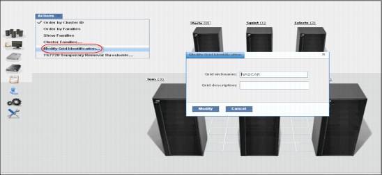
Figure 5-20 Modify Grid Identification window
Click one cluster image on the Grid Summary window, and the cluster summary window is loaded. To set the cluster names, click Action → Modify Cluster Identification. See Figure 5-21 for the Modify Cluster Identification window.
|
Tip: Use the same denomination in the cluster nickname as used in the DFSMS distributed library for the same cluster.
|

Figure 5-21 Modify Cluster Identification window
Both the cluster or grid nickname must be one to eight characters in length and composed of alphanumeric characters. Blank spaces and the following special characters are also allowed:
@ . - +
Blank spaces cannot be used in the first or last character position.
In the Grid description field or the Cluster description field, a brief description (up to 63 characters) is enough.
5.3.2 Verifying the composite and distributed library sequence numbers
You must ensure that distributed library and composite library sequence numbers are unique within the grid.
Both composite and distributed library sequence numbers are set into each TS7700 Virtualization Engine cluster by the IBM SSR during installation. The composite library ID defined in the TS7700 hardware must match the hardware configuration definition (HCD) as well as the Library-ID defined in ISMF. The distributed library ID defined in the TS7700 hardware must match the Library-ID defined in ISMF.
Even a stand-alone grid (stand-alone) TS7700 Virtualization Engine requires the definition of a composite and a distributed library ID (visualize a grid compounded by a lone cluster). The composite library ID is used for the host definition of the TS7700 Virtualization Engine logical library. The distributed library ID is used to link to the hardware aspects of the TS7700 Virtualization Engine, such as displaying scratch stacked volumes.
Check the distributed and composite library sequence numbers in the Grid Summary window of the MI, as shown in Figure 5-19 on page 213.
|
Restriction: The library ID must be five characters using a hexadecimal value (0-9, A-F). Do not use distributed library names starting with the letter V because on the z/OS host, a library name cannot start with the letter V.
|
5.3.3 Defining VOLSER ranges for physical volumes
After a cartridge is assigned to a logical library that is associated to a TS7740 Virtualization Engine by CAPs, it will be presented to the TS7740 Virtualization Engine Integrated Library Manager. The Integrated Library Manager uses the VOLSER ranges that are defined in its VOLSER Ranges table to set it to a proper Library Manager category. Define the proper policies in the VOLSER Ranges table before inserting the cartridges into the tape library.
|
Important:
•When using a TS3500 Tape Library, you must assign the CAP at the library hardware level before using the library with System z hosts.
•When using a TS3500 Tape Library and the TS7740 Virtualization Engine, physical volumes must fall within ranges that are assigned by the CAP to this TS7740 Virtualization Engine Logical Library in the TS3500 Tape Library.
|
Use the window shown in Figure 5-22 on page 216 to add, modify, or delete physical volume ranges. Unassigned physical volumes are listed in this window. When you observe an unassigned volume that belongs to this TS7740 Virtualization Engine, add a range that includes that volume to fix it. If an unassigned volume does not belong to this TS7740 Virtualization Engine, you must eject it and reassign it to the proper logical library in the TS3500 Tape Library.
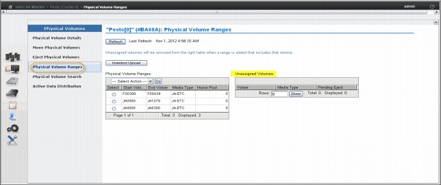
Figure 5-22 Physical Volume Ranges window
Click Inventory Upload to upload the inventory from the TS3500 and update any range or ranges of physical volumes that were recently assigned to that logical library. The VOLSER Ranges table displays the list of defined VOLSER ranges for a specific component. You can use the VOLSER Ranges table to create a new VOLSER range, or to modify or delete a predefined VOLSER range.
|
Important: Operator intervention is required to resolve unassigned volumes.
|
Figure 5-22 shows the status information that is displayed in the VOLSER Ranges table:
•Start Volser: The first VOLSER in a defined range
•End Volser: The last VOLSER in a defined range
•Media Type: The media type for all volumes in a certain VOLSER range. The following values are valid:
– JA-ETC: Enterprise Tape Cartridge
– JB-ETCL: Enterprise Extended-Length Tape Cartridge
– JC-EADC: Enterprise Advanced Data Cartridge
– JJ-EETC: Enterprise Economy Tape Cartridge
– JK-EAETC: Enterprise Advanced Economy Tape Cartridge
•Home Pool: The home pool to which the VOLSER range is assigned
Use the drop-down menu in the VOLSER Ranges table to add a new VOLSER range, or to modify or delete a predefined range:
•To add a new VOLSER range, select Add from the drop-down menu. Complete the fields for information that will be displayed in the VOLSER Ranges table, as defined previously.
•To modify a predefined VOLSER range, click the radio button from the Select column that appears in the same row as the name of the VOLSER range you want to modify. Select Modify from the drop-down menu and make your changes to the information that will be displayed in the VOLSER Ranges table.
|
Important: Modifying a predefined VOLSER range will not have any effect on physical volumes that are already inserted and assigned to the TS7740 Virtualization Engine. Only physical volumes that will be inserted after the VOLSER range modification will be changed.
|
The VOLSER entry fields must contain six characters. The characters can be letters, numerals, or a space. The two VOLSERs must be entered in the same format. Corresponding characters in each VOLSER must both be either alphabetic or numeric. For example, AAA998 and AAB004 are of the same form, but AA9998 and AAB004 are not. The VOLSERs that fall within a range are determined in the following manner. The VOLSER range is increased so that alphabetic characters are increased alphabetically, and numeric characters are increased numerically. For example, VOLSER range ABC000 - ABD999 results in a range of 2,000 VOLSERs (ABC000 - ABC999 and ABD000 - ABD999).
|
Restriction: The VOLSER ranges you define on the IBM TS3500 Tape Library apply to physical cartridges only. You can define logical volumes only through the TS7700 Virtualization Engine MI. See 5.3.15, “Inserting logical virtual volumes” on page 259 for more information.
|
For the TS7700 Virtualization Engine, no additional definitions are required at the hardware level other than setting up the correct VOLSER ranges at the TS3500 library.
Although you can now enter cartridges into the TS3500 library, complete the required definitions at the host before you insert any physical cartridges into the tape library.
The process of inserting logical volumes into the TS7700 Virtualization Engine is described in 5.3.15, “Inserting logical virtual volumes” on page 259.
5.3.4 Defining physical volume pools (TS7740 Virtualization Engine)
Physical volume pooling was first introduced as part of advanced policy management advanced functions in the IBM TotalStorage Virtual Tape Server (VTS).
Pooling physical volume allows you to separate your data into separate sets of physical media, treating each media group in a specific way. For instance, you might want to segregate production data from test data, or encrypt part of your data. All of this can be accomplished by defining physical volume pools appropriately. Also, you can define the reclaim parameters for each specific pool to best suit your specific needs. The TS7700 Virtualization Engine MI is used for pool property definitions.
Items under Physical Volumes in the MI only apply to clusters with an associated tape library (TS7740 Virtualization Engine). Trying to access those windows from a TS7720 results in the following HYDME0995E message:
This cluster is not attached to a physical tape library.
Use the window shown in Figure 5-23 on page 218 to view or modify settings for physical volume pools, which manage the physical volumes used by the TS7700 Virtualization Engine.

Figure 5-23 Physical Volume Pools
The Physical Volume Pool Properties table displays the encryption setting and media properties for every physical volume pool defined for a given cluster in the grid.
You can use the Physical Volume Pool Properties table to view encryption and media settings for all installed physical volume pools. To view and modify additional details of pool properties, select a pool or pools from this table and then select either Modify Pool Properties or Modify Encryption Settings from the drop-down menu.
|
Tip: Pools 1 - 32 are preinstalled. Pool 1 functions as the default pool and is used if no other pool is selected. All other pools must be defined before they can be selected.
|
The Physical Volume Pool Properties table displays the media properties and encryption settings for every physical volume pool defined for a given cluster in the grid. This table contains two tabs: Pool Properties and Physical Tape Encryption Settings:
•The following information is under the Pool Properties tab:
– Pool: Lists the pool number, which is a whole number in the range of 1 - 32, inclusive.
– Media Class: Lists that the supported media class of the storage pool is 3592.
– First Media (Primary): The primary media type that the pool can borrow or return to the common scratch pool (Pool 0). The following values are valid:
Any 3592 Any 3592
JA Enterprise Tape Cartridge (ETC)
JB Enterprise Extended-Length Tape Cartridge (ETCL)
JC Enterprise Advanced Data Cartridge (EADC)
JJ Enterprise Economy Tape Cartridge (EETC)
JK Enterprise Advanced Economy Tape Cartridge (EAETC)
To modify pool properties, select the check box next to one or more pools listed in the Physical Volume Pool Properties table and select Properties from the drop-down menu. The Pool Properties table is displayed.
You can modify the fields Media Class and First Media, defined previously, and the following fields:
– Second Media (Secondary): Lists the second choice of media type from which the pool can borrow. The options listed exclude the media type selected for the First Media. The following values are valid:
Any 3592 Any 3592
JA Enterprise Tape Cartridge (ETC)
JB Enterprise Extended-Length Tape Cartridge (ETCL)
JC Enterprise Advanced Data Cartridge (EADC)
JJ Enterprise Economy Tape Cartridge (EETC)
JK Enterprise Advanced Economy Tape Cartridge (EAETC)
None The only option available if the Primary Media type is Any 3592.
– Borrow Indicator: Defines how the pool is populated with scratch cartridges. The following values are valid:
Borrow, Return A cartridge is borrowed from the common scratch pool and returned when emptied.
Borrow, Keep A cartridge is borrowed from the common scratch pool and retained, even after being emptied.
No Borrow, Return A cartridge cannot be borrowed from the common scratch pool, but an emptied cartridge is placed in the common scratch pool. This setting is used for an empty pool.
No Borrow, Keep A cartridge cannot be borrowed from the common scratch pool, and an emptied cartridge will be retained.
– Reclaim Pool: Lists the pool to which logical volumes are assigned when reclamation occurs for the stacked volume on the selected pool.
– Maximum Devices: Lists the maximum number of physical tape drives that the pool can use for premigration.
– Export Pool: Lists the type of export that is supported if the pool is defined as an Export Pool, which is the pool from which physical volumes are exported (From the Physical Volume Pools page, click the Pool Properties tab; select the check box next to each pool to be modified; select Modify Pool Properties from the Physical volume pools drop-down menu; and click Go to open the Modify Pool Properties page.) The following values are valid:
Not Defined The pool is not defined as an Export pool.
Copy Export The pool is defined as a Copy Export pool.
– Export Format: The media format used when writing volumes for export. This function can be used when the physical library recovering the volumes supports a different media format than the physical library exporting the volumes. This field is only enabled if the value in the Export Pool field is Copy Export. The following values are valid:
Default The highest common format supported across all drives in the library. This is also the default value for the Export Format field.
E06 Format of a 3592-E06 Tape Drive.
E07 Format of a 3592-E07 Tape Drive.
– Days Before Secure Data Erase: Lists the number of days a physical volume that is a candidate for Secure Data Erase can remain in the pool without access to a physical stacked volume. Each stacked physical volume possesses a timer for this purpose, which is reset when a logical volume on the stacked physical volume is accessed. Secure Data Erase occurs at a later time, based on an internal schedule. Secure Data Erase renders all data on a physical stacked volume inaccessible. The valid range of possible values is 1 - 365. Clicking to clear the check box deactivates this function.
– Days Without Access: Lists the number of days the pool can persist without access to set a physical stacked volume. Each physical stacked volume has a timer for this purpose, which is reset when a logical volume is accessed. The reclamation occurs at a later time, based on an internal schedule. The valid range of possible values is 1 - 365. Clicking to clear the check box deactivates this function.
– Age of Last Data Written: Lists the number of days the pool has persisted without write access to set a physical stacked volume as a candidate for reclamation. Each physical stacked volume has a timer for this purpose, which is reset when a logical volume is accessed. The reclamation occurs at a later time, based on an internal schedule. The valid range of possible values is 1 - 365. Clicking to clear the check box deactivates this function.
– Days Without Data Inactivation: Lists the number of sequential days the pool’s data ratio has been higher than the Maximum Active Data to set a physical stacked volume as a candidate for reclamation. Each physical stacked volume has a timer for this purpose, which is reset when data is inactivated. The reclamation occurs at a later time, based on an internal schedule. The valid range of possible values is 1-365. Clicking to clear the check box will deactivate this function. If deactivated, this field is not used as a criteria for reclamation.
– Maximum Active Data: Lists the ratio of the amount of active data in the entire physical stacked volume capacity. This field is used in conjunction with Days Without Data Inactivation. The valid range of possible values is 5 - 95(%). This function is disabled if Days Without Data Inactivation is not selected.
– Reclaim Threshold: Lists the percentage that is used to determine when to perform reclamation of free storage on a stacked volume. When the amount of active data on a physical stacked volume drops below this percentage, a reclaim operation will be performed on the stacked volume. The valid range of possible values is 5 - 95(%). The default value is 10%. Clicking to clear the check box deactivates this function.
•The following information is under the Physical Tape Encryption Settings tab:
– Pool: Lists the pool number. This number is a whole number 1 - 32, inclusive.
– Encryption: Lists the encryption state of the pool. The possible values are Enabled or Disabled.
– Key Mode 1: Lists the encryption mode used with Key Label 1. The following values are valid for this field:
• Clear Label: The data key is specified by the key label in clear text.
• Hash Label: The data key is referenced by a computed value corresponding to its associated public key.
• None: Key Label 1 is disabled.
• Dash (-): The default key is in use.
– Key Label 1: Lists the current encryption key Label 1 for the pool. The label must consist of ASCII characters and cannot exceed 64 characters. Leading and trailing blanks are removed, but an internal space is allowed. Lowercase characters are internally converted to uppercase upon storage, and therefore key labels are reported using uppercase characters.
If the encryption state indicates Disabled, this field is blank. If the default key is used, the value in this field is default key.
– Key Mode 2: Lists the encryption mode used with Key Label 2. The following values are valid for this field:
• Clear Label: The data key is specified by the key label in clear text.
• Hash Label: The data key is referenced by a computed value corresponding to its associated public key.
• None: Key Label 2 is disabled.
• Dash (-): The default key is in use.
– Key Label 2: The current encryption key Label 2 for the pool. The label must consist of ASCII characters and cannot exceed 64 characters. Leading and trailing blanks are removed, but an internal space is allowed. Lowercase characters are internally converted to uppercase upon storage, and therefore key labels are reported using uppercase characters.
If the encryption state is Disabled, this field is blank. If the default key is used, the value in this field is default key.
To modify encryption settings for one or more physical volume pools, use the following steps (see Figure 5-24 and Figure 5-25 on page 222 for reference):
1. Open the Physical Volume Pools page (Figure 5-24).

Figure 5-24 Modifying encryption parameters for a pool
|
Tip: A tutorial is available at the Physical Volume Pools page to show how to modify encryption properties.
|
2. Click the Physical Tape Encryption Settings tab.
3. Select the check box next to each pool to be modified.
4. Click Select Action → Modify Encryption Settings.
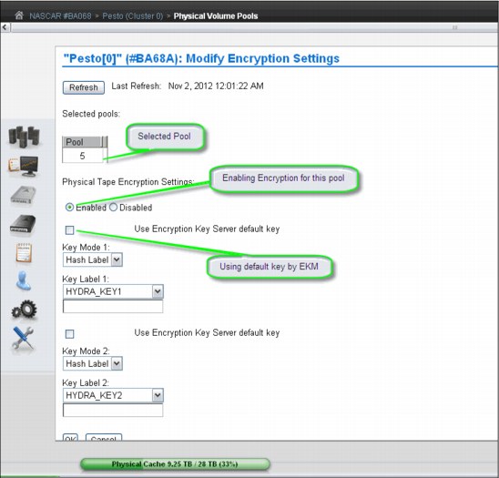
Figure 5-25 Modify encryption settings parameters
In this window, you can modify values for any of the following controls:
•Encryption:
This field is the encryption state of the pool and can have the following values:
– Enabled: Encryption is enabled on the pool.
– Disabled: Encryption is not enabled on the pool.
When this value is selected, key modes, key labels, and check boxes are disabled.
•Use Encryption Key Manager default key
Select this check box to populate the Key Label field by using a default key provided by the encryption key manager.
|
Restriction: Your encryption key manager software must support default keys to use this option.
|
This check box occurs before both Key Label 1 and Key Label 2 fields; you must select this check box for each label to be defined using the default key.
If this check box is selected, the following fields are disabled:
– Key Mode 1
– Key Label 1
– Key Mode 2
– Key Label 2
•Key Mode 1
This field is the encryption mode that is used with Key Label 1. The following values are valid:
– Clear Label: The data key is specified by the key label in clear text.
– Hash Label: The data key is referenced by a computed value corresponding to its associated public key.
– None: Key Label 1 is disabled. The default key is in use.
•Key Label 1
This field is the current encryption key Label 1 for the pool. The label must consist of ASCII characters and cannot exceed 64 characters. Leading and trailing blanks are removed, but an internal space is allowed. Lowercase characters are internally converted to uppercase upon storage, and therefore, key labels are reported using uppercase characters.
•Key Mode 2
This field is the encryption mode used with Key Label 2. The following values are valid:
– Clear Label: The data key is specified by the key label in clear text.
– Hash Label: The data key is referenced by a computed value that corresponds to its associated public key.
•None
Indicates that the Key Label 2 is disabled. The default key is in use.
•Key Label 2
This field is the current encryption key Label 2 for the pool. The label must consist of ASCII characters and cannot exceed 64 characters. Leading and trailing blanks are removed, but an internal space is allowed. Lowercase characters are internally converted to uppercase upon storage, and therefore key labels are reported using uppercase characters.
To complete the operation, click OK. To abandon the operation and return to the Physical Volume Pools page, click Cancel.
Reclaim thresholds
To optimize utilization of the subsystem resources, such as CPU cycles and tape drive usage, you can inhibit space reclamation during predictable busy periods of time and adjust reclamation thresholds to the optimum point in your TS7740 through the MI. The reclaim threshold is the percentage used to determine when to perform the reclamation of free space in a stacked volume. When the amount of active data on a physical stacked volume drops below this percentage, the volume becomes eligible for reclamation. Reclamation values can be in the range of 5 - 95%, and default value is 10%. Clicking to clear the check box deactivates this function.
Throughout the data lifecycle, new logical volumes are created and old logical volumes become obsolete. Logical volumes are migrated to physical volumes, occupying real space there. When a logical volume becomes obsolete, that space becomes a waste of capacity in that physical tape. In other words, the active data level of that volume is decreasing over time. TS7740 actively monitors the active data in its physical volumes. Whenever this active data level crosses the reclaim threshold that is defined in the Physical Volume Pool in which that volume belongs, the TS7400 sets that volume in a candidate list for reclamation.
Reclamation will copy active data from that volume to another stacked volume in the same pool. When the copy finishes and the volume becomes empty, the volume is returned to available SCRATCH status. This cartridge is now available for use and will be returned to the common scratch pool or directed to the specified reclaim pool, according to the Physical Volume Pool definition.
|
Clarification: Each reclamation task uses two tape drives (source and target) in a tape-to-tape copy function. The TS7740 Tape Volume Cache is not used for reclamation.
|
Multiple reclamation processes can run in parallel. The maximum number of reclaim tasks is limited by the TS7740, based on the number of available back-end drives as shown in Table 5-1.
Table 5-1 Installed drives versus maximum reclaim tasks
|
Number of available drives
|
Maximum number of reclaims
|
|
3
|
1
|
|
4
|
1
|
|
5
|
1
|
|
6
|
2
|
|
7
|
2
|
|
8
|
3
|
|
9
|
3
|
|
10
|
4
|
|
11
|
4
|
|
12
|
5
|
|
13
|
5
|
|
14
|
6
|
|
15
|
6
|
|
16
|
7
|
The reclamation level for the physical volumes must be set by using the Physical Volume Pools window in the TS7740 MI. See Figure 5-26.
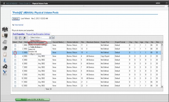
Figure 5-26 Physical Volume Pools
Select a pool and click Modify Pool Properties in the drop-down menu to set the reclamation level and other policies for that pool. See Figure 5-27 on page 226.
In this example, the reclamation level is set to 35%, the Borrow-Return policy is in effect for this pool, and reclaimed physical cartridges stay in the same Pool 3, except borrowed volumes, which will be returned to the original pool.
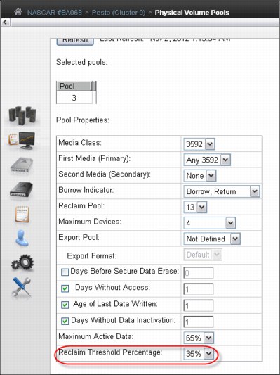
Figure 5-27 Pool properties
Reclamation enablement
To minimize any impact on TS7700 Virtualization Engine activity, the storage management software monitors resource utilization in the TS7700 Virtualization Engine, and enables or disables reclamation as appropriate. You can optionally prevent reclamation activity at specific times of day by specifying an Inhibit Reclaim Schedule in the TS7740 Virtualization Engine MI (Figure 5-28 on page 229 shows an example). However, the TS7740 Virtualization Engine determines whether reclamation is to be enabled or disabled once an hour depending on the number of available scratch cartridges and will ignore the Inhibit Reclaim schedule if the TS7740 Virtualization Engine is almost out of scratch category.
|
Tip: The maximum number of inhibit reclaim schedules is 14.
|
Using the Bulk Volume Information Retrieval (BVIR) process, you can run the query for PHYSICAL MEDIA POOLS to monitor the amount of active data on stacked volumes to help you plan for a reasonable and effective reclaim threshold percentage. You can also use the Host Console Request function to obtain the physical volume counts.
Although reclamation is enabled, stacked volumes might not always be going through the process all the time. Other conditions must be met, such as stacked volumes that meet one of the reclaim policies and drives available to mount the stacked volumes.
Reclamation for a volume is stopped by the TS7700 Virtualization Engine internal management functions if a tape drive is needed for a recall or copy (because these are of a higher priority) or a logical volume is needed for recall off a source or target tape being used in the reclaim process. If this happens, reclamation is stopped for this physical tape after the current logical volume move is complete.
Pooling is enabled as a standard feature of the TS7700 Virtualization Engine, even if you are only using one pool. Reclamation can occur on multiple volume pools at the same time, and processing multiple tasks for the same pool. One of the reclamation methods selects the volumes for processing based on the percentage of active data. For example, if the reclaim threshold was set to 30% generically across all volume pools, the TS7700 Virtualization Engine selects all the stacked volumes from 0% to 29% of the remaining active data. The reclaim tasks then process the volumes from least full (0%) to most full (29%) up to the defined reclaim threshold of 30%.
Individual pools can have separate reclaim policies set. The number of pools can also influence the reclamation process because the TS7740 Virtualization Engine always evaluates the stacked media starting with Pool 1.
The scratch count for physical cartridges also affects reclamation. The scratch state of pools is assessed in the following manner:
1. A pool enters a Low scratch state when it has access to fewer than 50 but two or more stacked volumes.
2. A pool enters a Panic scratch state when it has access to fewer than two empty stacked volumes.
“Access to” includes any borrowing capability, which means that if the pool is configured for borrowing, and if there are more than 50 cartridges in the common scratch pool, the pool will not enter the Low scratch state.
Whether borrowing is configured or not, as long as each pool has two scratch cartridges, the Panic Reclamation mode is not entered. Panic Reclamation mode is entered when a pool has fewer than two scratch cartridges and no more scratch cartridges can be borrowed from any other pool defined for borrowing. Borrowing is described in “Physical volume pooling” on page 41.
|
Important: A physical volume pool running out of scratch cartridges might stop mounts in the TS7740, impacting your operation. Mistakes in pool configuration (media type, borrow and return, home pool, and so on) or operating with an empty common scratch pool might lead to this situation.
|
Consider that one reclaim task consumes two drives for the data move, and CPU cycles. When a reclamation starts, these drives are busy until the volume being reclaimed is empty. If you raise the reclamation threshold level too high, the result is larger amounts of data to be moved, with resultant penalty in resources that are needed for recalls and premigration. The default setting for the reclamation threshold level is 10%. Generally, you need to operate with a reclamation threshold level in the range of 10 - 30%. Also, see Chapter 9, “Operation” on page 413 to fine-tune this function, considering your peak load and using new host functions. Pools in either scratch state (Low or Panic state) get priority for reclamation.
Table 5-2 summarizes the thresholds.
Table 5-2 Reclamation priority table
|
Priority
|
Condition
|
Reclaim schedule honored
|
Active data threshold% honored
|
Number of concurrent reclaims
|
Comments
|
|
1
|
Pool in Panic scratch state
|
No
|
No
|
1, regardless of idle drives
|
|
|
2
|
Priority move
|
Yes or No
|
No
|
1, regardless of idle drives
|
If a volume is within 10 days of a Secure Data Erasure (SDE) and still has active data on it, it will be reclaimed at this priority. An SDE priority move will honor the inhibit reclaim schedule.
For a TS7740 MI-initiated priority move, the option to honor the inhibit
reclaim schedule is given to the operator. |
|
3
|
Pool in Low scratch state
|
Yes
|
Yes
|
1, regardless of idle drives
|
Volumes that are subject to reclaim because of Maximum Active Data, Days Without Access, Age of Last Data Written, and Days Without Data Inactivation will use priority 3 or 4 reclamation.
|
|
4
|
Normal reclaim
|
Yes
|
Yes, pick from all eligible pools
|
(Number of idle drives divided by 2) minus 1
8 drv: 3 max
16 drv: 7 max
|
Volumes that are subject to reclaim because of Maximum Active Data, Days Without Access, Age of Last Data Written, and Days Without Data Inactivation will use priority 3 or 4 reclamation.
|
|
Tips:
•A physical drive is considered idle when no activity has occurred for the previous ten minutes.
•The Inhibit Reclaim schedule is not honored by the Secure Data Erase function for a volume that has no active data.
|
Inhibit Reclaim schedule
The Inhibit Reclaim schedule defines when the TS7700 Virtualization Engine must refrain from reclaim operations. During times of heavy mount activity, it might be desirable to make all of the physical drives available for recall and premigration operations. If these periods of heavy mount activity are predictable, you can use the Inhibit Reclaim schedule to inhibit reclaim operations for the heavy mount activity periods.
To define the Inhibit Reclaim schedule, click Management Interface → Settings → Cluster Settings, which opens the window shown in Figure 5-28.

Figure 5-28 Inhibit Reclaim schedules
The Schedules table (Figure 5-29) displays the day, time, and duration of any scheduled reclamation interruption. All inhibit reclaim dates and times are first displayed in Coordinated Universal Time (UTC) and then in local time. Use the drop-down menu on the Schedules table to add a new Reclaim Inhibit Schedule, or modify or delete an existing schedule, as shown in Figure 5-28.

Figure 5-29 Add Inhibit Reclaim schedule
5.3.5 Defining scratch (Fast Ready) categories
In Release 3.0 of the TS7700 Virtualization Engine, all categories that are defined as scratch inherit the Fast Ready attribute. There is no longer a need to use the MI to set the Fast
Ready attribute to scratch categories; however, the MI is still needed to indicate which categories are scratch.
The MOUNT FROM CATEGORY command is not exclusively used for scratch mounts. Therefore, the TS7700 Virtualization Engine cannot assume that any MOUNT FROM CATEGORY is for a scratch volume.
The Fast Ready attribute provides a definition of a category to supply scratch mounts. For z/OS, it depends on the definitions. The TS7700 MI provides a way to define one or more scratch (Fast Ready) categories. Figure 5-30 shows the Categories window. You can add a scratch (Fast Ready) category by using the Add Scratch Category pull-down (Maintenance Interface with Release 3.0).
When defining a scratch (Fast Ready) category, you can also set up an expire time, as well as further define the expire time as an Expire Hold time.
The actual category hexadecimal number depends on the software environment and on the definitions in the SYS1.PARMLIB member DEVSUPxx for library partitioning. Also, the DEVSUPxx member must be referenced in the IEASYSxx member to be activated.

Figure 5-30 Categories
In Figure 5-30, use this page to add, modify, or delete a scratch (Fast Ready) category of virtual volumes. You can also use this page to view total volumes defined by custom, inserted, and damaged categories. The Categories table uses the following values and descriptions:
•Categories:
– Scratch
Categories within the user-defined private range 0x0001 through 0xEFFF that are defined as scratch (Fast Ready).
– Private
Custom categories established by a user, within the range of 0x0001 though 0xEFFF.
– Damaged
A system category identified by the number 0xFF20. Virtual volumes in this category are considered damaged.
– Insert
A system category identified by the number 0xFF00. Inserted virtual volumes are held in this category until moved by the host into a scratch category.
•Owning Cluster
Names of all clusters in the grid.
•Counts
The total number of virtual volumes according to category type, category, or owning cluster.
•Scratch Expired
The total number of scratch volumes per owning cluster that are expired. The total of all scratch expired volumes is the number of ready scratch volumes.
|
Number of virtual volumes: You cannot arrive at the total number of virtual volumes by adding all volumes shown in the Counts column because some rare, internal categories are not displayed on the Categories table. Additionally, movement of virtual volumes between scratch and private categories can occur multiple times per second and any snapshot of volumes on all clusters in a grid is obsolete by the time a total count completes.
|
You can use the Categories table to add, modify, or delete a scratch category, or to change the way that information is displayed.
Figure 5-31 shows the Add Category window, which opens by selecting Add Scratch Categories as shown in Figure 5-30 on page 230.

Figure 5-31 Scratch (Fast Ready) Categories: Add Category
The Add Category window shows these fields:
•Category
A four-digit hexadecimal number that identifies the category. The following characters are valid characters for this field:
A-F, 0-9
|
Note: Do not use category name 0000 or "FFxx", where xx equals 0 - 9 or A - F. 0000 represents a null value, and "FFxx" is reserved for hardware.
|
•Expire
The amount of time after a virtual volume is returned to the scratch (Fast Ready) category before its data content is automatically delete-expired.
A volume becomes a candidate for delete-expire once all the following conditions are met:
– The amount of time since the volume entered the scratch (Fast Ready) category is equal to or greater than the Expire Time.
– The amount of time since the volume’s record data was created or last modified is greater than 12 hours.
– At least 12 hours has passed since the volume was migrated out of or recalled back into disk cache.
|
Note: If you select No Expiration, volume data never automatically delete-expires.
|
•Set Expire Hold
Check this box to prevent the virtual volume from being mounted or having its category and attributes changed before the expire time has elapsed.
Checking this field activates the hold state for any volumes currently in the given scratch (Fast Ready) category and for which the expire time has not yet elapsed. Clearing this field removes the access restrictions on all volumes currently in the hold state within this scratch (Fast Ready) category.
|
Restriction: Trying to mount a non-expired volume that belongs to a scratch (Fast Ready) category with Expire Hold on will result in an error.
|
Beginning in Release 2.1, a category change to a held volume is allowed so long as the target category is not scratch (Fast Ready). An expire-held volume can be moved to a private (non-Fast Ready) category and cannot be moved to another scratch (Fast Ready) category with this option enabled.
|
Tip: Add a comment to DEVSUPnn to ensure that the scratch (Fast Ready) categories are updated when the category values in DEVSUPnn are changed. They need to be in sync at all times.
|
See Appendix H, “Library Manager volume categories” on page 953 for the scratch mount category for each software platform. In addition to the z/OS DFSMS default value for the scratch mount category, you can define your own scratch category to the TS7700 Virtualization Engine. In this case, you must also add your own scratch mount category to the Fast Ready category list.
5.3.6 Defining the logical volume expiration time
You define the expiration time from the MI window shown in Figure 5-31 on page 231. If the Delete Expired Volume Data setting is not used, logical volumes that have been returned to scratch will still be considered active data, allocating physical space in tape cartridges on the TS7740 Virtualization Engine. In that case, only rewriting this logical volume will expire the old data, therefore allowing that physical space occupied by old data to be reclaimed later. With the Delete Expired Volume Data setting, the data that is associated with volumes that have been returned to scratch are expired after a specified time period and their physical space in tape can be reclaimed.
For example, assume that you have 20,000 logical volumes in SCRATCH status at any point in time, that the average amount of data on a logical volume is 400 MB, and that the data compresses at a 2:1 ratio. The space occupied by the data on those scratch volumes is 4,000,000 MB or the equivalent of fourteen 3592-JA cartridges. By using the Delete Expired Volume Data setting, you can reduce the number of cartridges required in this example by 14. The parameter Expire Time specifies the amount of time in hours, days, or weeks. The data continues to be managed by the TS7700 Virtualization Engine after a logical volume is returned to scratch before the data associated with the logical volume is deleted. A minimum of 1 hour and a maximum of 32,767 hours (approximately 195 weeks) can be specified.
|
Remember:
•Scratch (Fast Ready) categories are global settings within a multicluster grid. Therefore, each defined scratch (Fast Ready) category and the associated Delete Expire settings are valid on each cluster of the grid.
•The Delete Expired Volume Data setting applies also to TS7720 clusters. If it is not used, logical volumes that have been returned to scratch will still be considered active data, allocating physical space in the Tape Volume Cache (TVC). Therefore, setting an expiration time on TS7720 is important to maintain an effective cache usage by deleting expired data.
|
Specifying a value of zero used to work as the No Expiration option in older levels. Zero in this field causes an error message as shown in Figure 5-32 on page 234. You see the message because the data associated with the volume is managed as it was before the addition of this option, meaning that it is never deleted. In essence, specifying a value (other than zero) provides a “grace period” from when the logical volume is returned to scratch until its associated data is eligible for deletion. A separate Expire Time can be set for each category defined as Fast Ready.

Figure 5-32 Invalid expire time value
Expire Time
Figure 5-31 on page 231 shows the number of hours or days in which logical volume data categorized as scratch (Fast Ready) will expire. If the field is set to 0, the categorized data will never expire. The minimum Expire Time is 1 hour and the maximum Expire Time is 195 weeks, 1,365 days, or 32,767 hours. The Expire Time default value is 24 hours.
Establishing the Expire Time for a volume occurs as a result of specific events or actions. The following list shows the possible events or actions and their effect on the Expire Time of a volume:
•A volume is mounted.
The data that is associated with a logical volume will not be deleted, even if it is eligible, if the volume is mounted. Its Expire Time is set to zero, meaning it will not be deleted. It will be re-evaluated for deletion when its category is subsequently assigned.
•A volume’s category is changed.
Whenever a volume is assigned to a category, including assignment to the same category in it currently exists, it is re-evaluated for deletion.
•Expiration.
If the category has a non-zero Expire Time, the volume’s data is eligible for deletion after the specified time period, even if its previous category had a different non-zero Expire Time.
•No action.
If the volume’s previous category had a non-zero Expire Time or even if the volume was already eligible for deletion (but has not yet been selected to be deleted) and the category to which it is assigned has an Expire Time of zero, the volume’s data is no longer eligible for deletion. Its Expire Time is set to zero.
•A category’s Expire Time is changed.
If a user changes the Expire Time value through the scratch (Fast Ready) categories menu on the TS7700 Virtualization Engine MI, the volumes assigned to the category are re-evaluated for deletion.
•Expire Time is changed from non-zero to zero.
If the Expire Time is changed from a non-zero value to zero, volumes assigned to the category that currently have a non-zero Expire Time are reset to an Expire Time of zero. If a volume was already eligible for deletion, but had not been selected for deletion, the volume’s data is no longer eligible for deletion.
•Expire Time is changed from zero to non-zero.
Volumes currently assigned to the category continue to have an Expire Time of zero. Volumes subsequently assigned to the category will have the specified non-zero Expire Time.
•Expire Time is changed from non-zero to non-zero.
Volumes maintain their current Expire Time. Volumes subsequently assigned to the category will have the updated non-zero Expire Time.
After a volume’s Expire Time has been reached, it is eligible for deletion. Not all data that is eligible for deletion will be deleted in the hour that it is first eligible. Once an hour, the TS7700 Virtualization Engine selects up to 1,000 eligible volumes for data deletion. The volumes are selected based on the time that they became eligible, with the oldest ones being selected first. Up to 1,000 eligible volumes for the TS7700 Virtualization Engine in the library are selected first.
5.3.7 Events
Verify that all raised events are being reported to the attached System z hosts, by clicking Monitor → Events and selecting the Send Future Events to Host table, which indicates that the Current setting is Enabled, as shown in Figure 5-33, so that the information can be sent to the hosts.

Figure 5-33 Events
5.3.8 Defining TS7700 constructs
To exploit the Outboard Policy Management functions, you must define four constructs:
• Storage Group (SG)
• Management Class (MC)
• Storage Class (SC)
• Data Class (DC)
These construct names are passed down from the z/OS host and stored with the logical volume. The actions defined for each construct are performed by the TS7700 Virtualization Engine. For non-z/OS hosts, you can manually assign the constructs to logical volume ranges.
Storage Groups
On the z/OS host, the Storage Group construct determines into which tape library a logical volume is written. Within the TS7740 Virtualization Engine, the Storage Group construct allows you to define the storage pool to which you want to place the logical volume.
Even before you define the first Storage Group, there is always at least one Storage Group present. This is the default Storage Group, which is identified by eight dashes (--------). This Storage Group cannot be deleted, but you can modify it to point to another storage pool. You can define up to 256 Storage Groups, including the default.
Use the window shown in Figure 5-34 to add, modify, or delete a Storage Group used to define a primary pool for logical volume premigration.

Figure 5-34 Storage Groups
The Storage Groups table displays all existing Storage Groups available for a given cluster.
You can use the Storage Groups table to create a new Storage Group, modify an existing Storage Group, or delete a Storage Group.
The following status information is listed in the Storage Groups table:
•Name: The name of the Storage Group
Each Storage Group within a cluster must have a unique name. The following characters are valid for this field:
A - Z Alphabetic characters
0 - 9 Numerals
$ Dollar sign
@ At sign
* Asterisk
# Number sign
% Percent
•Primary Pool: The primary pool for premigration
Only validated physical primary pools can be selected. If the cluster does not possess a physical library, this column will not be visible and the MI will categorize newly created Storage Groups using pool 1.
•Description: A description of the Storage Group
Use the drop-down menu in the Storage Groups table to add a new Storage Group, or to modify or delete an existing Storage Group.
To add a new Storage Group, select Add from the drop-down menu. Complete the fields for the information that is displayed in the Storage Groups table.
|
Restriction: If the cluster is not attached to a physical library, the Primary Pool field will not be available in the Add or Modify menu options.
|
To modify an existing Storage Group, click the radio button from the Select column that appears adjacent to the name of the Storage Group you want to modify. Select Modify from the drop-down menu. Complete the fields for information that will be displayed in the Storage Groups table.
To delete an existing Storage Group, select the button in the Select column next to the name of the Storage Group you want to delete. Select Delete from the drop-down menu. You are prompted to confirm your decision to delete a Storage Group. If you select Yes, the Storage Group will be deleted. If you select No, your request to delete is canceled.
|
Important: Do not delete any existing Storage Group if there are still logical volumes assigned to this Storage Group.
|
Management Classes
You can define, through the Management Class, whether you want to have a dual copy of a logical volume within the same TS7740 Virtualization Engine. In a grid configuration, you will most likely choose to copy logical volumes over to the other TS7700 cluster instead of creating a second copy in the same TS7700 Virtualization Engine. In a stand-alone configuration, however, you might want to protect against media failures by using the dual copy capability. The second copy of a volume can be in a pool that is designated as a Copy Export pool. See 2.3.31, “Copy Export” on page 76 for more information.
If you want to have dual copies of selected logical volumes, you must use at least two storage pools because the copies cannot be written to the same storage pool as the original logical volumes.
A default Management Class is always available. It is identified by eight dashes (--------) and cannot be deleted. You can define up to 256 Management Classes, including the default. Use the window shown in Figure 5-35 to define, modify, or delete the Management Class that defines the TS7700 Virtualization Engine copy policy for volume redundancy.
The Current Copy Policy table displays the copy policy in force for each component of the grid. If no Management Class is selected, this table will not be visible. You must select a Management Class from the Management Classes table to view copy policy details.
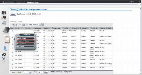
Figure 5-35 Management Classes
The Management Classes table (Figure 5-35) displays defined Management Class copy policies that can be applied to a cluster.
You can use the Management Classes table to create a new Management Class, modify an existing Management Class, or delete one or more existing Management Classes. The default Management Class can be modified, but cannot be deleted. The default name of Management Class uses eight dashes (--------).
The following status information is displayed in the Management Classes table:
•Name: The name of the Management Class
Valid characters for this field are A - Z, 0 - 9, $, @, *, #, and %. The first character of this field cannot be a number. This is the only field that cannot be modified after it is added.
•Secondary Pool: The target pool in the volume duplication
If the cluster does not possess a physical library, this column will not be visible and the MI will categorize newly created Storage Groups using pool 0.
•Description: A description of the Management Class definition
The value in this field must be between 1 and 70 characters in length.
•Scratch Mount Candidate
The cluster or clusters that are the candidates for scratch mounts. Clusters displayed in this field are selected first for scratch mounts of the volumes associated with the Management Class. If no clusters are displayed, the scratch mount process remains a random selection routine that includes all available clusters. See 5.4.4, “Defining scratch mount candidates” on page 268.
•Retain Copy Mode (Yes or No)
Retain Copy mode honors the original Copy Consistency Policy that is in place in the cluster where the volume was created. With this, undesired copies are not created throughout the grid. See Chapter 2, “Architecture, components, and functional characteristics” on page 15 for more details.
•The Cluster Copy Policy provides the ability to define where and when copies are made.
Use the drop-down menu in the Management Classes table to add a new Management Class, modify an existing Management Class, or delete one or more existing Management Classes.
To add a new Management Class, select Add from the drop-down menu and click Go. Complete the fields for information that will be displayed in the Management Classes table. You can create up to 256 Management Classes per TS7700 Virtualization Engine Grid.
|
Tip: If cluster is not attached to a physical library, the Secondary Pool field will not be available in the Add option.
|
The Copy Action drop-down menu is adjacent to each cluster in the TS7700 Virtualization Engine Grid. Use the Copy Action menu to select, for each component, the copy mode to use in volume duplication. The following actions are available from this menu:
•No Copy: No volume duplication will occur if this action is selected.
•Rewind Unload (RUN): Volume duplication occurs when the Rewind Unload command is received. The command returns only after the volume duplication completes successfully.
•Deferred: Volume duplication occurs at a later time based on the internal schedule of the copy engine.
•Synchronous Copy: Provides tape copy capabilities up to synchronous-level granularity across two clusters within a multicluster grid configuration. See “Synchronous mode copy” on page 70 for additional information about Synchronous mode copy settings and considerations.
Figure 5-36 shows the Add Management Class window.

Figure 5-36 Add Management Class
To modify an existing Management Class, select the check box in the Select column that is in the same row as the name of the Management Class that you want to modify. You can modify only one Management Class at a time. Select Modify from the drop-down menu and click Go. Of the fields listed in the Management Classes table, or available from the Copy Action drop-down menu, you are able to change all of them except the Management Class name.
Figure 5-37 shows the Modify Management Classes window.

Figure 5-37 Modify Management Classes window
To delete one or more existing Management Classes, select the check box in the Select column that is in the same row as the name of the Management Class that you want to delete. Select multiple check boxes to delete multiple Management Classes. Select Delete from the drop-down menu and click Go.
|
Important: Do not delete any existing Management Class if there are still logical volumes assigned to this Management Class.
You cannot delete the default Management Class.
|
Storage Classes
By using the Storage Class construct, you can influence when a logical volume is removed from cache.
A default Storage Class is always available. It is identified by eight dashes (--------) and cannot be deleted. Use the window shown in Figure 5-38 on page 241 to define, modify, or delete a storage class used by the TS7700 Virtualization Engine to automate storage management through the classification of data sets and objects.
The Storage Classes table lists storage classes that are defined for each component of the grid.

Figure 5-38 Storage Classes window on a TS7740
The Storage Classes table displays defined storage classes available to control data sets and objects within a cluster. Although storage classes are visible from all TS7700 clusters, only those clusters attached to a physical library can alter TVC preferences. TS7700 clusters that do not possess a physical library do not remove physical volumes from the tape cache, so the TVC preference for these clusters is always Preference Level 1.
Use the Storage Classes table to create a new storage class, or modify or delete an existing storage class. The default storage class can be modified, but cannot be deleted. The default storage class uses eight dashes as the name (--------).
The following status information is displayed in the Storage Classes table:
•Name: The name of the storage class.
Valid characters for this field are A - Z, 0 - 9, $, @, *, #, and %. The first character of this field might not be a number. The value in this field must be 1 - 8 characters in length.
•Tape Volume Cache Preference: The preference level for the storage class.
It determines how soon volumes are removed from cache following their copy to tape. This information can only be modified if the selected cluster possesses a physical library. If the selected cluster is a TS7720 Virtualization Engine (disk-only), volumes in that cluster’s cache display a Level 1 preference. The following values are valid:
– Use IART
Volumes are removed according to the Initial Access Response Time (IART) of the TS7700 Virtualization Engine.
– Level 0
Volumes are removed from the TVC as soon as they are copied to tape.
– Level 1
Copied volumes remain in the TVC until additional space is required, and then they are the first volumes removed to free space in the cache. This is the default preference level assigned to new preference groups.
•Volume Copy Retention Group: The name of the group that defines the preferred Auto Removal policy applicable to the logical volume.
The Volume Copy Retention Group provides additional options to remove data from a TS7720 Virtualization Engine (disk-only) as the active data reaches full capacity. Volumes become candidates for removal if an appropriate number of copies exist on peer clusters and the volume copy retention time has elapsed since the volume was last accessed. Volumes in each group are removed in order based on their least recently used (LRU) access times. The volume copy retention time describes the number of hours that a volume remains in cache before becoming a candidate for removal.
This field is displayed only if the cluster is a disk-only cluster or part of a hybrid grid (a hybrid grid combines TS7700 clusters that both attach and do not attach to a physical library). If the logical volume is in a scratch (Fast Ready) category and resides on a disk-only cluster, removal settings no longer apply to the volume and the volume is a candidate for removal. In this instance, the value displayed for the Volume Copy Retention Group is accompanied by a warning icon:
– Prefer Remove
Removal candidates in this group are removed before removal candidates in the Prefer Keep group.
– Prefer Keep
Removal candidates in this group are removed after removal candidates in the Prefer Remove group.
– Pinned
Copies of volumes in this group are never removed from the accessing cluster. The volume copy retention time does not apply to volumes in this group. Volumes in this group that are subsequently moved to scratch become priority candidates for removal.
|
Important: Care must be taken when assigning volumes to this group to avoid cache overruns.
|
•Volume Copy Retention Time: The minimum amount of time (in hours) after a logical volume copy was last accessed that the copy can be removed from cache.
The copy is said to be expired after this time has passed, and the copy then becomes a candidate for removal. Possible values include any values in the range of 0 - 65,536. The default is 0.
|
Tip: This field is only visible if the selected cluster does not attach to a physical library and all the clusters in the grid operate at a microcode level of 8.7.0.xx or higher.
|
If the Volume Copy Retention Group displays a value of Pinned, this field is disabled.
•Description: A description of the storage class definition.
The value in this field must be 1 - 70 characters in length.
Use the drop-down menu in the Storage Classes table to add a new storage class or modify or delete an existing storage class.
To add a new storage class, select Add from the drop-down menu. Complete the fields for the information that will be displayed in the Storage Classes table. You can create up to 256 storage classes per TS7700 Virtualization Engine Grid.
To modify an existing storage class, click the radio button from the Select column that appears in the same row as the name of the storage class that you want to modify. Select Modify from the drop-down menu. Of the fields listed in the Storage Classes table, you will be able to change all of them except for the storage class name.
To delete an existing storage class, click the radio button from the Select column that appears in the same row as the name of the storage class that you want to delete. Select Delete from the drop-down menu. A dialog box opens where you confirm the storage class deletion. Select Yes to delete the storage class, or select No to cancel the delete request.
|
Important: Do not delete any existing storage class if there are still logical volumes assigned to this storage class.
|
Figure 5-39 shows the Add Storage Class window on a TS7720.

Figure 5-39 Add Storage Class window on a TS7720
Data Classes
From a z/OS perspective (SMS-managed tape), the DFSMS Data Class defines the following information:
•Media type parameters
•Recording technology parameters
•Compaction parameters
For the TS7700 Virtualization Engine, only the Media type, Recording technology, and Compaction parameters are used. The use of larger logical volume sizes is controlled through Data Class.
A default Data Class is always available. It is identified by eight dashes (--------) and cannot be deleted.
Use the window shown in Figure 5-40, to define, modify, or delete a TS7700 Virtualization Engine Data Class. The Data Class is used to automate storage management through the classification of data sets.

Figure 5-40 Data Classes window
The Data Classes table (Figure 5-40) displays the list of Data Classes defined for each cluster of the grid.
You can use the Data Classes table to create a new Data Class, or modify or delete an existing Data Class. The default Data Class can be modified, but cannot be deleted. The default Data Class shows the name as eight dashes (--------).
The following status information is displayed in the Data Classes table:
•Name: The name of the Data Class
Valid characters for this field are A - Z, 0 - 9, $, @, *, #, and %. The first character of this field cannot be a number. The value in this field must be between 1 and 8 characters in length.
•Virtual Volume Size (mebibyte, MiB): The logical volume size of the Data Class
It determines the maximum number of MiB for each logical volume in a defined class. The following values are valid:
Insert Media Class Logical volume size is not defined; the Data Class will not be defined by a maximum logical volume size. You can use 1,000 MiB, 2,000 MiB, 4,000 MiB, or 6,000 MiB.
|
Restriction: Support for 25,000 MiB logical volumes of maximum size is available by a request for price quotation (RPQ) only and supported by a code level of 8.7.0.140 or higher.
|
•Logical Write Once Read Many (WORM)
It specifies whether logical WORM (LWORM) is set for the Data Class. LWORM is the virtual equivalent of WORM tape media, achieved through software emulation.
|
Note: This setting is available only when all clusters in a grid operate a code level of 8.6.0.xx or higher.
|
The following values are valid for this field:
– Yes
LWORM is set for the Data Class. Volumes belonging to the Data Class are defined as LWORM.
– No
LWORM is not set. Volumes belonging to the Data Class are not defined as LWORM. This is the default value for a new Data Class.
•Description: A description of the Data Class definition
The value in this field must be at least 0 and no greater than 70 characters in length.
Use the drop-down menu on the Data Classes table to add a new Data Class, or modify or delete an existing Data Class. Figure 5-41 shows the Add Data Class window.

Figure 5-41 Add Data Class window
To add a new Data Class, select Add from the drop-down menu and click Go. Complete the fields for the information that will display in the Data Classes table.
|
Tip: You can create up to 256 Data Classes per TS7700 Virtualization Engine Grid.
|
To modify an existing Data Class, select the check box in the Select column that appears in the same row as the name of the Data Class that you want to modify. Select Modify from the drop-down menu and click Go. Of the fields listed in the Data Classes table, you can change all of them except the default Data Class name.
To delete an existing Data Class, click the radio button from the Select column that appears in the same row as the name of the Data Class you want to delete. Select Delete from the drop-down menu and click Go. A dialog box opens where you can confirm the Data Class deletion. Select Yes to delete the Data Class, or select No to cancel the delete request.
|
Important: Do not delete any existing Data Class if there are still logical volumes assigned to this Data Class.
|
5.3.9 TS7700 licensing
This section describes how to view information about, activate, or remove the following feature licenses from the TS7700 Virtualization Engine cluster:
•Peak data throughput increments
•Logical volume increments
•Cache enablement
•Grid enablement
•Selective Device Access Control enablement
•Encryption configuration enablement
•Dual port grid connection enablement
•Specific RPQ enablement (for example, 25,000 MiB logical volume enablement)
|
Clarification: Cache enablement license key entry applies only on a TS7740 Virtualization Engine configuration because a TS7720 Virtualization Engine does not have a 1-TB cache enablement feature (FC5267).
|
The amount of disk cache capacity and performance capability are enabled using feature license keys. You will receive feature license keys for the features that you have ordered. Each feature increment allows you to tailor the subsystem to meet your disk cache and performance needs.
Use the Feature Licenses window (Figure 5-42 on page 247) to activate feature licenses in the TS7700 Virtualization Engine. To open the window, select Activate New Feature License from the list and click Go. Enter the license key into the fields provided and select Activate.

Figure 5-42 Feature Licenses window
To remove a license key, select the feature license to be removed, select Remove Selected Feature License from the list, and click Go.
|
Important: Do not remove any installed peak data throughput features because removal can affect host jobs.
FC5267, 1 TB Cache Enablement, is not removable after activation.
|
When you select Activate New Feature License, the Feature License entry window opens as shown in Figure 5-43. When you enter a valid feature license key and click Activate, the feature will be activated.
|
Tip: Performance Increments become active immediately. Cache Increments become active within 30 minutes.
|

Figure 5-43 Activate New Feature Licenses window
5.3.10 Defining Encryption Key Server addresses
Set the Encryption Key Server addresses in the TS7700 Virtualization Engine (Figure 5-44 on page 249).

Figure 5-44 Encryption Key Server Addresses
To watch a tutorial that shows the properties of Encryption Key Management, click the View tutorial link. If the cluster is not attached to a physical library, the window displays an error message as shown in Figure 5-45.

Figure 5-45 Encryption Key Server Addresses error message
The Encryption Key Server assists encryption-enabled tape drives in generating, protecting, storing, and maintaining encryption keys that are used to encrypt information being written to and decrypt information being read from tape media (tape and cartridge formats).
The following settings are used to configure the TS7700 Virtualization Engine connection to an Encryption Key Server (Figure 5-44 on page 249):
•Primary key server address: The key server name or IP address that is primarily used to access the encryption key server. This address can be a fully qualified host name or an
IP address in IPv4 or IPv6 format. This field is not required if you do not want to connect to an encryption key server.
IP address in IPv4 or IPv6 format. This field is not required if you do not want to connect to an encryption key server.
A valid IPv4 address is 32 bits and consists of four decimal numbers, each ranging from 0 to 255, separated by periods, for example:
98.104.120.12
A valid IPv6 address is a 128-bit hexadecimal value separated into 16-bit fields by colons, for example:
3afa:1910:2535:3:110:e8ef:ef41:91cf
Leading zeros can be omitted in each field, so that :0003: can be written as :3:. A double colon (::) can be used once per address to replace multiple fields of zeros. For example, this address:
3afa:0:0:0:200:2535:e8ef:91cf
can be written as:
3afa::200:2535:e8ef:91cf
A fully qualified host name is a domain name that uniquely and absolutely names a computer. It consists of the host name and the domain name. The domain name is one or more domain labels that place the computer in the domain name server (DNS) naming hierarchy. The host name and the domain name labels are separated by periods and the total length of the hostname cannot exceed 255 characters.
•Primary key server port: The port number of the primary key server. Valid values are any whole number between 0 and 65535; the default value is 3801. This field is only required if a primary key address is used.
•Secondary key server address: The key server name or IP address that is used to access the Encryption Key Server when the primary key server is unavailable.
This address can be a fully qualified host name or an IP address in IPv4 or IPv6 format. This field is not required if you do not want to connect to an encryption key server.
See the primary key server address description for IPv4, IPv6, and fully qualified host name value parameters.
•Secondary key manager port: The port number of the secondary key server. Valid values are any whole number between 0 and 65535; the default value is 3801. This field is only required if a secondary key address is used.
•Using the Ping Test: Use the Ping Test buttons to check cluster network connection to a key server after changing a cluster’s address or port. If you change a key server address or port and do not submit the change before using the Ping Test button, you will receive the following warning:
In order to perform a ping test you must first submit your address and/or port changes.
Once the ping test has been issued, you will receive one of two following messages:
– The ping test against the address "<address>" on port "<port>" was successful.
– The ping test against the address "<address>" on port "<port>" from "<cluster>" has failed. The error returned was:<error text>.
Click Submit Changes to save changes to any of these settings.
|
Consideration: The two encryption key servers must be set up on separate machines to provide redundancy. Connection to a key manager is required to read encrypted data.
|
5.3.11 Defining Simple Network Management Protocol
Use the window shown in Figure 5-46 to view or modify the Simple Network Management Protocol (SNMP) configured on an IBM Virtualization Engine TS7700 Cluster.
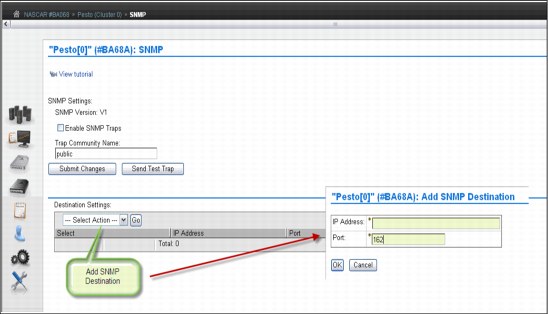
Figure 5-46 SNMP settings
Use the window to configure SNMP traps that will log operation history events, such as login occurrences, configuration changes, status changes (vary on or off and service prep), shut down, and code updates. SNMP is a networking protocol that allows an IBM Virtualization Engine TS7700 to automatically gather and transmit information about alerts and status to other entities in the network.
SNMP Settings section
Use this section to configure global settings that apply to SNMP traps on an entire cluster. You can configure the following settings:
•SNMP Version: The SNMP version defines the protocol used in sending SNMP requests and is determined by the tool you are using to monitor SNMP traps. Different versions of SNMP traps work with different management applications. The only possible value on TS7700 Virtualization Engine is V1. No alternate version is supported.
•Enable SMP Traps: This check box enables or disables SNMP traps on a cluster. If the check box is selected, SNMP traps on the cluster are enabled. If the check box is not selected (the default), SNMP traps on the cluster are disabled.
•Trap Community Name: This name identifies the trap community and is sent along with the trap to the management application. This value behaves as a password. The management application will not process an SNMP trap unless it is associated with the correct community. This value must be 1 - 15 characters in length and consists of Unicode characters.
•Send Test Trap: This button sends a test SNMP trap to all destinations listed in the Destination Settings table using the current SNMP trap values. The Enable SNMP Traps check box does not need to be checked to send a test trap. If the SNMP test trap is received successfully and the information is correct, select Submit Changes.
•Submit Changes: Select this button to submit changes to any of the global settings, including the SNMP Version, Enable SNMP Traps, and Trap Community Name fields.
Destination Settings section
Use the Destination Settings table to add, modify, or delete a destination for SNMP trap logs. You can add, modify, or delete a maximum of 16 destination settings at one time. You can configure the following settings:
•IP Address: The IP address of the SNMP server. This value can take any of the following formats: IPv4, IPv6, a hostname resolved by the machine (such as localhost), or a fully-qualified domain name (FQDN) if a domain name server (DNS) is provided. A value in this field is required.
A valid IPv4 address is 32 bits, consists of four decimal numbers, each ranging from 0 to 255, separated by periods, for example:
98.104.120.12
A valid IPv6 address is a 128-bit hexadecimal value separated into 16-bit fields by colons, for example:
3afa:1910:2535:3:110:e8ef:ef41:91cf
Leading zeros can be omitted in each field, so that :0003: can be written as :3:. A double colon (::) can be used once per address to replace multiple fields of zeros, for example:
3afa:0:0:0:200:2535:e8ef:91cf
can be written this way:
3afa::200:2535:e8ef:91cf
A fully qualified host name is a domain name that uniquely and absolutely names a computer. It consists of the host name and the domain name. The domain name is one or more domain labels that place the computer in the DNS naming hierarchy. The host name and the domain name labels are separated by periods and the total length of the hostname cannot exceed 255 characters.
•Port: This port is where the SNMP trap logs are sent. This value must be a number between 0 and 65535. A value in this field is required.
|
Restriction: A user with read-only permissions cannot modify the contents of the Destination Settings table.
|
Use the Select Action drop-down menu in the Destination Settings table to add, modify, or delete an SNMP trap destination. Destinations are changed in the vital product data (VPD) as soon as they are added, modified, or deleted. These updates do not depend on your selecting Submit Changes on the window:
•Add SNMP destination: Select this menu item to add an SNMP trap destination for use in the IBM Virtualization Engine TS7700 Grid.
•Modify SNMP destination: Select this menu item to modify an SNMP trap destination that is used in the IBM Virtualization Engine TS7700 Grid.
•Confirm delete SNMP destination: Select this menu item to delete an SNMP trap destination used in the IBM Virtualization Engine TS7700 Grid.
5.3.12 Enabling IPv6
IPv6 and Internet Protocol Security (IPSec) are supported beginning with release 3.0 of Licensed Internal Code by the 3957-V07 and 3957-VEB configurations of the TS7700 Virtualization Engine.
|
Tip: The client network must use whether IPv4 or IPv6 for all functions, such as MI, key manager server, SNMP, Lightweight Directory Access Protocol (LDAP), and Network Time Protocol (NTP). Mixing IPv4 and IPv6 is not currently supported.
|
Figure 5-47 shows how to enable IPv6 in a TS7700 Virtualization Engine.

Figure 5-47 Configuring IPv6
For more information about IPv6, See “IPv6 support” on page 145 and “InfoCenter Settings window” on page 551.
5.3.13 Enabling IPSec
Beginning with Release 3.0 of Licensed Internal Code, the 3957-V07 and 3957-VEB configurations of the TS7700 Virtualization Engine will support IPSec over the grid links.
|
Caution: Enabling grid encryption significantly affects the performance of the TS7700 Virtualization Engine.
|
Figure 5-48 shows how to enable the IPSec for the TS7700 cluster.

Figure 5-48 Enabling IPSec in the grid links
In a multicluster grid, the user can choose which link will be encrypted by checking the box in front of the beginning and ending cluster for the selected link. Figure 5-48 depicts a two-cluster grid, which is the reason why there is only one option to check.
For more information about IPSec, see “Internet Protocol Security for grid links” on page 51. Also, see the IBM Virtualization Engine TS7700 Customer Information Center 3.0.1.0:
5.3.14 Security Settings section
Use this section to set up and check the security settings for the TS7700 Virtualization Engine grid. From this page in the MI, you can perform these functions:
•Add a new policy
•Modify an existing policy
•Assign an authentication policy
•Test the security setting before running the application
•Delete an existing policy
Each cluster in your configuration can have a different security policy assigned to it. However, only one policy can be in effect on a cluster at a time.
Figure 5-49 on page 255 shows the Security Settings panel.

Figure 5-49 Security settings
For Session Timeout, you specify the number of hours and minutes that the MI can be idle before the current session expires and the user is redirected to the login page.
The Authentication Policies table shows the defined policies in the TS7700 Virtualization Engine Grid. Policies can be Local, which means that users and their assigned roles are replicated throughout the grid. Or, policies can be External, which stores user and group data on a separate server, verifying the relationship between users, groups, and authorization roles whenever a user logs in to a cluster. Direct LDAP and Storage Authentication Service policies are included in the external policies.
|
Important: When a Storage Authentication Service policy is enabled for a cluster, service personnel are required to log in with the setup user or group. Be sure that an account has been created for the service personnel before enabling storage authentication.
|
Figure 5-50 on page 256 shows the Add Storage Authentication Service Policy panel.
Storage Authentication Service Policy
The Storage Authentication Service Policy uses a centrally managed role-based access control policy (RBAC) that authenticates and authorizes users by using the System Storage Productivity Center to authenticate users to an LDAP server.

Figure 5-50 Add Storage Authentication Service Policy
Direct LDAP Policy
Figure 5-51 on page 257 shows the Add Direct LDAP Policy menu. Use this menu to add an RBAC policy that will authenticate and authorize users through direct communication with an LDAP server.
|
Important: When a Storage Authentication Service policy is enabled for a cluster, service personnel are required to log in with the setup user or group. Be sure that an account has been created for the service personnel before enabling storage authentication.
|

Figure 5-51 Add Direct LDAP Policy
The fields in both Figure 5-51 and Figure 5-50 on page 256 are defined in the following list:
•Policy Name: The name of the policy that defines the authentication settings. The policy name is a unique value that consists of one to 50 Unicode characters. Heading and trailing blank spaces are trimmed, although internal blank spaces are permitted. The name of the Local policy is “Local”. Authentication policy names, either Local or user-created, cannot be modified after they are created.
•Primary Server URL: The primary URL for the Storage Authentication Service1. The value in this field consists of 1 - 254 Unicode characters and takes one of the following formats:
– https://<server_address>:secure_port/TokenService/services/Trust
– ldaps://<server_address>:secure_port
– ldap://<server_address>:port
If a domain name server (DNS) address needs to be used here, a DNS must be activated and configured on the Cluster Network settings page. See 9.2.9, “The Settings icon” on page 553.
•Alternate Server URL: The alternate URL for the Storage Authentication Service if the primary URL cannot be accessed. The value is the same as the value described in the previous item.1
•Server Authentication: Values are required in the user id and password fields if IBM WebSphere Application Server security is enabled on the WebSphere Application Server hosting the Authentication Service, or if anonymous access is disabled on the LDAP server:
– User ID: The user name used with HTTP basic authentication for authenticating to the Storage Authentication Service. Maximum length of 254 Unicode characters.
– Password: The password used with HTTP basic authentication for authenticating to the Storage Authentication Service. Maximum length of 254 Unicode characters.
•Direct LDAP: Values in the following fields are required if secure authentication is used or anonymous connections are disabled in the LDAP server:
– User Distinguished Name: Used to authenticate to the LDAP authentication service. Maximum length of 254 Unicode characters, for example: CN=Administrator,CN=users,DC=mycompany,DC=com
– Password: The password to authenticate to the LDAP authentication service. Maximum length of 254 Unicode characters.
– Base Distinguished Name: The distinguished name (DN) uniquely identifies a set of entries in a domain. Maximum length of 254 Unicode characters.
– Username Attribute: The attribute name used for the username during authentication. This field is required and contains the value uid, by default. Maximum length of 61 Unicode characters.
– Password Attribute: The attribute name used for the password during authentication. This field is required and contains the value userPassword, by default. Maximum length of 61 Unicode characters.
– Group Member Attribute: The attribute name used to identify the group during authorization. This field is optional and contains the value member, by default. Maximum length of 61 Unicode characters.
– Group Name Attribute: The attribute name used to identify the group during authorization. This field is optional and contains the value cn, by default. Maximum length of 61 Unicode characters.
– Username filter: Used to filter and validate an entered username. This field is optional and contains the value (uid={0}), by default. Maximum length of 254 Unicode characters.
– Group Name filter: Used to filter and validate an entered group name. This field is optional and contains the value (cn={0}), by default. Maximum length of 254 Unicode characters.
Local policy
The Local policy is the default authentication policy. When enabled, it is in effect for all clusters on the grid. It is mutually exclusive with the Storage Authentication Service. Local policy can be modified to add, change or delete individual accounts, but the policy itself cannot be deleted.
Figure 5-52 on page 259 shows the Modify Local Policy panel.

Figure 5-52 Modify Local Accounts
Use this panel to modify the Local policy settings for the TS7700 Virtualization grid. You can define the following information:
•Whether accounts defined by a policy can expire, and if so, the number of days that a password can be used before it expires. Possible values are 1 through 999.
•Whether accounts defined by a policy can be locked after a number of successive incorrect password retries (1 to 9).
5.3.15 Inserting logical virtual volumes
Use the Insert Virtual Volumes window (Figure 5-53 on page 260) to insert a range of logical volumes in the TS7700 Virtualization Engine grid. Logical volumes inserted into an individual cluster will be available to all clusters within a grid configuration.

Figure 5-53 TS7700 Virtualization Engine MI Insert Virtual Volumes window
During logical volume entry processing on z/OS, even if the library is online and operational for a specific host, at least one device needs to be online (or have been online) for that host for the library to be able to send the volume entry attention interrupt to that host. If the library is online and operational, but there are no online devices to a specific host, that host will not receive the attention interrupt from the library unless a device had previously been varied online.
To work around this limitation, ensure that at least one device is online (or had been online) to each host or use the LIBRARY RESET,CBRUXENT command to initiate cartridge entry processing from the host. This task is especially important if you only have one host attached to the library that owns the volumes being entered. In general, after you have entered volumes into the library, if you do not see the expected CBR36xxI cartridge entry messages being issued, you can use the LIBRARY RESET,CBRUXENT command from z/OS to initiate cartridge entry processing. The LIBRARY RESET,CBRUXENT command causes the host to ask for any volumes in the insert category.
Up to now, as soon as OAM started, and if volumes were in the Insert category, entry processing started without giving you the chance to stop entry processing the first time that OAM is started.
Now, the LI DISABLE,CBRUXENT command can be used without starting the OAM address space. This approach gives you the chance to stop entry processing before the OAM address space initially starts.
The table at the top of Figure 5-53 on page 260 shows the current information about the number of logical volumes in the TS7700 Virtualization Engine:
•Currently Inserted: The total number of logical volumes inserted into the TS7700 Virtualization Engine
•Maximum Allowed: The total maximum number of logical volumes that can be inserted
•Available Slots: The available slots remaining for logical volumes to be inserted, which is obtained by subtracting the Currently Inserted logical volumes from the Maximum Allowed
To view the current list of logical volume ranges in the TS7700 Virtualization Engine Grid, enter a logical volume range and click Show.
Use the following fields if you want to insert a new logical volume range action:
•Starting VOLSER: This is the first logical volume to be inserted. The range for inserting logical volumes begins with this VOLSER number.
•Quantity: Select this option to insert a set number of logical volumes beginning with the Starting VOLSER. Enter the quantity of logical volumes to be inserted in the adjacent text field. You can insert up to 10,000 logical volumes at one time.
•Ending VOLSER: Select this option to insert a range of logical volumes. Enter the ending VOLSER number in the adjacent text field.
•Initially owned by: Indicates the name of the cluster that will own the new logical volumes. Select a cluster from the drop-down menu.
•Media type: Indicates the media type of the logical volume (volumes). The following values are valid:
– Cartridge System Tape (400 MiB)
– Enhanced Capacity Cartridge System Tape (800 MiB)
•Set Constructs: Select this check box to specify constructs for the new logical volume (or volumes), then use the drop-down menu under each construct to select a predefined construct name. You can specify the use of any or all of the following constructs:
– Storage Group
– Storage Class
– Data Class
– Management Class
|
Important: When using z/OS, do not specify constructs when the volumes are added. Instead, they are assigned during job processing when a volume is mounted and written from the load point.
|
To insert a range of logical volumes, complete the fields listed and click Insert. You are prompted to confirm your decision to insert logical volumes. To continue with the insert operation, click Yes. To abandon the insert operation without inserting any new logical volumes, click No.
|
Restriction: You can insert up to ten thousand (10,000) logical volumes at one time. This applies to both inserting a range of logical volumes and inserting a quantity of logical volumes.
|
5.4 Virtualization Engine multicluster grid definitions
This section covers several available configuration definitions with the TS7700.
5.4.1 Data access and availability characteristics
A TS7700 Virtualization Engine Grid configuration provides the following data access and availability characteristics:
•Direct host attachment to a Virtualization Engine TS7700
•Accessibility of logical volumes through virtual device addresses on the TS7700s in the grid configuration
•Selection of location of the logical volume for access
•Whether a copy is available at another TS7700 cluster
•Volume ownership and ownership takeover
•Service prep/service mode
•Consequences of a link failure in your grid
These grid operational characteristics need to be carefully considered and thoroughly planned by you and your IBM representative. The infrastructure requirements need to be addressed in advance.
5.4.2 TS7700 grid configuration considerations for a two-cluster grid
The TS7700 grid configuration provides for the automatic replication of data and can be used in a variety of high availability and disaster recovery situations. When connected together at the same location, a grid configuration can also help facilitate higher availability to data. The topics in this section provide information for you to consider in planning for a disaster recovery or high availability solution using the Virtualization Engine TS7700 grid configuration.
|
Tip: All clusters in a multicluster grid must have FC4015, Grid Enablement, installed. This includes existing stand-alone clusters that are being used to create a multicluster grid.
|
Figure 5-54 shows a basic two-way TS7740 grid configuration.

Figure 5-54 TS7740 Virtualization Engine in a two-cluster grid configuration
|
Clarification: In the TS7720 Virtualization Engine Grid configuration, disregard the physical library attachment.
|
Figure 5-55 shows a two-cluster hybrid example.
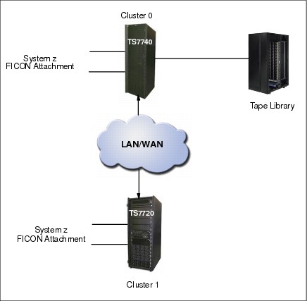
Figure 5-55 TS7700 Virtualization Engine in a hybrid two-cluster grid configuration
Each TS7700 cluster provides two or four FICON host attachments and 256 virtual tape device addresses. The clusters in a grid configuration are connected together through two or four 1 Gbps copper (RJ-45) or shortwave fiber Ethernet links (single-ported or dual-ported). Alternatively, two longwave fiber Ethernet links can be provided. The Ethernet links are used for the replication of data between clusters, and passing control information and access between a local cluster’s virtual tape device and a logical volume’s data in a remote cluster’s TS7700 cache.
5.4.3 Defining grid copy mode control
When upgrading a stand-alone cluster to a grid, FC4015, Grid Enablement, must be installed on all clusters in the grid. Also, you must set up the Copy Consistency Points in the Management Class definitions on all clusters in the new grid.
The data consistency point is defined in the Management Classes construct definition through the MI. You can perform this task only for an existing grid system. In a stand-alone cluster configuration, you will see only your stand-alone cluster in the Modify Management Class definition. Figure 5-56 on page 265 shows the Modify Management Class window.
|
Remember: With a stand-alone cluster configuration, copy mode must be set to Rewind Unload.
|
See “Management Classes” on page 237 for more information.

Figure 5-56 Example of Modify Management Classes page
To open the Management Classes window (Figure 5-57), click Constructs → Management Classes under the Welcome Admin menu. Select the Management Class name and select Modify from the Select Action drop-down menu.

Figure 5-57 Management Classes
Click Go. The next window (Figure 5-58) is where you can modify the copy consistency by using the Copy Action table, and then clicking OK. In this example, the TS7700 Virtualization Engine (named Pesto) is part of a multicluster grid configuration. This additional drop-down menu is displayed only if a TS7700 Virtualization Engine is part of a multicluster grid environment.

Figure 5-58 Modify Management Classes
As shown in Figure 5-58, you can choose between three consistency points per cluster:
•No Copy: No copy (NC) is made to this cluster.
•Rewind Unload (RUN): A valid version of the logical volume has been copied to this cluster as part of the volume unload processing.
•Deferred: A replication of the modified logical volume is made to this cluster after the volume had been unloaded (DEF).
•Synchronous copy: Provides tape copy capabilities up to synchronous-level granularity across two clusters within a multicluster grid configuration. See “Synchronous mode copy” on page 70.
|
Tip: A stand-alone grid (stand-alone TS7700 Virtualization Engine) always uses Rewind Unload (RUN) as the Data Consistency Point.
|
Also, check the following links for detailed information about this subject:
•IBM Virtualization Engine TS7700 Series Best Practices - TS7700 Hybrid Grid Usage:
•IBM Virtualization Engine TS7700 Series Best Practices - Copy Consistency Points:
•IBM Virtualization Engine TS7700 Series Best Practices - Synchronous Mode Copy:
Define Copy Policy Override settings
With the TS7700 Virtualization Engine, you can define and set the optional override settings that influence the selection of the I/O TVC and replication responses. The settings are specific to a cluster in a multicluster grid configuration, which means that each cluster can have separate settings, if you want. The settings take effect for any mount requests received after the settings were saved. Mounts already in progress are not affected by a change in the settings. You can define and set the following settings:
•Prefer local cache for scratch (Fast Ready) mount requests
•Prefer local cache for private (non-Fast Ready) mount requests
•Force volumes mounted on this cluster to be copied to the local cache
•Allow fewer RUN consistent copies before reporting RUN command complete
•Ignore cache preference groups for copy priority
You can view and modify these settings from the TS7700 Virtualization Engine MI by clicking Settings → Cluster Setting → Copy Policy Override as shown in Figure 5-59.

Figure 5-59 Copy Policy Override
You can select the following settings in the MI window:
•Prefer local cache for Fast Ready mount requests
A scratch (Fast Ready) mount selects a local copy as long as a cluster Copy Consistency Point is not specified as No Copy in the Management Class for the mount. The cluster is not required to have a valid copy of the data.
•Prefer local cache for private (non-Fast Ready) mount requests
This override causes the local cluster to satisfy the mount request as long as the cluster is available and the cluster has a valid copy of the data, even if that data is only resident on physical tape. If the local cluster does not have a valid copy of the data, the default cluster selection criteria applies.
•Force volumes mounted on this cluster to be copied to the local cache
For a private (non-Fast Ready) mount, this override causes a copy to be performed on the local cluster as part of mount processing. For a scratch (Fast Ready) mount, this setting has the effect of overriding the specified Management Class with a Copy Consistency Point of Rewind-Unload for the cluster. This does not change the definition of the Management Class, but serves to influence the Replication policy.
•Allow fewer RUN consistent copies before reporting RUN command complete
If selected, the value entered for “Number of required RUN consistent copies including the source copy” will be used to determine the number of copies to override before the Rewind Unload operation reports as complete. If this option is not selected, the Management Class definitions are to be used explicitly. Thus, the number of RUN copies can be from one to the number of clusters in the grid.
•Ignore cache preference groups for copy priority
If this option is selected, copy operations ignore the cache preference group when determining the priority of volumes copied to other clusters.
|
Restriction: In a Geographically Dispersed Parallel Sysplex (GDPS), all three Copy Policy Override settings (cluster overrides for certain I/O and copy operations) must be selected on each cluster to ensure that wherever the GDPS primary site is, this TS7700 Virtualization Engine cluster is preferred for all I/O operations.
If the TS7700 Virtualization Engine cluster of the GDPS primary site fails, you must perform the following recovery actions:
1. Vary virtual devices from a remote TS7700 Virtualization Engine cluster online from the primary site of the GDPS host.
2. Manually invoke, through the TS7700 Virtualization Engine MI, a Read/Write Ownership Takeover, unless Automated Ownership Takeover Manager (AOTM) has already transferred ownership.
|
5.4.4 Defining scratch mount candidates
Scratch allocation assistance (SAA) is an extension of the device allocation assistance (DAA) function for scratch mount requests. SAA filters the list of clusters in a grid to return to the host a smaller list of candidate clusters specifically designated as scratch mount candidates.
If you have a grid with two or more clusters, you can define scratch mount candidates. For example in a hybrid configuration, the SAA function can be used to direct certain scratch allocations (workloads) to one or more TS7720 Virtualization Engines for fast access, while other workloads can be directed to TS7740 Virtualization Engines for archival purposes.
Clusters not included in the list of scratch mount candidates are not used for scratch mounts at the associated Management Class unless those clusters are the only clusters either known to be available and configured to the host.
Before SAA is visible or operational, the following prerequisites must be true:
•All clusters in the grid have a microcode level of 8.20.0.xx. The necessary z/OS host software support is installed. See Authorized Program Analysis Report (APAR) OA32957 in the Tech docs Library link in the Related information section for additional information.
•The z/OS environment uses Job Entry Subsystem (JES) 2.
|
Tip: JES3 does not support DAA or SAA. If the composite library is being shared between JES2 and JES3, do not enable SAA through the Scratch Mount Candidate option on the Management Classes assigned to JES3 jobs. This can cause job abends to occur in JES3.
|
•SAA is enabled with the host LIBRARY REQUEST command:
LIBRARY REQUEST,library-name,SETTING,DEVALLOC,SCRATCH,ENABLE
where library-name = composite-library-name
Disabled is the default setting.
•An adequate number of devices connected to the scratch mount candidate clusters are online at the host.
|
Remember: If the clusters are online, but too few or no devices are online at the host, jobs using SAA can go into allocation recovery. See 10.4.5, “Allocation and scratch allocation assistance” on page 683 for more details.
|
As shown in Figure 5-60, by default all clusters are chosen as scratch mount candidates. Select which clusters are candidates by Management Class. If no clusters are checked, the TS7700 will default to all clusters as candidates.
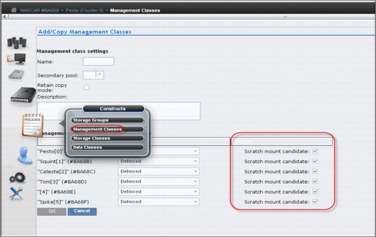
Figure 5-60 Scratch mount candidate list in Add Management Classes window
Each cluster in a grid can provide a unique list of candidate clusters. Clusters with an ‘N’ copy mode, such as cross-cluster mounts, can still be candidates. Figure 5-61 shows an example of modifying an existing Management Class and selecting only the three clusters that are getting a valid copy of the data as scratch mount candidates.

Figure 5-61 Scratch mount candidate selection at associated Management Class
5.4.5 Retain Copy mode
Retain Copy mode is an optional setting where a volume’s existing Copy Consistency Points are honored instead of applying the Copy Consistency Points defined at the mounting cluster. This applies to private volume mounts for reads or write appends. It is used to prevent more copies of a volume being created in the grid than desired. This is important in a grid with three or more clusters that has two or more clusters online to a host.
This parameter is set in the Management Classes window for each Management Class when you add a Management Class. Figure 5-62 on page 271 shows the Management Classes window and the Retain Copy mode check box.
|
Note: The Retain Copy mode option is available only on private (non-Fast Ready) virtual volume mounts.
|

Figure 5-62 Retain Copy mode selection in the Management Classes window
5.4.6 Defining cluster families
If you have a grid with three or more clusters, you can define cluster families.
This function introduces a concept of grouping clusters together into families. Using cluster families, you will be able to define a common purpose or role to a subset of clusters within a grid configuration. The role assigned, for example, production or archive, will be used by the TS7700 microcode to make improved decisions for tasks, such as replication and TVC selection. For example, clusters in a common family are favored for TVC selection, or replication can source volumes from other clusters within its family before using clusters outside of its family.
Use the Cluster Families option on the Actions menu of the Grid Summary panel to add, modify, or delete a cluster family. Figure 5-63 on page 272 shows the menu for the cluster families.
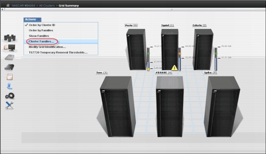
Figure 5-63 Cluster Families menu option
To view or modify cluster family settings, first verify that these permissions are granted to your assigned user role. Then, select Cluster Families from the Actions menu to perform the following actions:
|
Note: The cluster family configuration is available only on clusters that operate microcode level of 8.6.0.xx or higher and are part of a grid.
|
Add a family
Click Add to create a new cluster family. A new cluster family placeholder is created to the right of any existing cluster families. Enter the name of the new cluster family in the active Name text box. Cluster family names must be 1 - 8 characters in length and consist of Unicode characters. Each family name must be unique. To add a cluster to the new cluster family, move a cluster from the Unassigned Clusters area by following instructions in “Move a cluster” on page 272.
|
Restriction: You can create a maximum of eight cluster families.
|
Move a cluster
You can move one or more clusters between existing cluster families to a new cluster family from the Unassigned Clusters area, or to the Unassigned Clusters area from an existing cluster family:
•Select a cluster: A selected cluster is identified by its highlighted border. Select a cluster from its resident cluster family or the Unassigned Clusters area by using one of the following ways:
– Clicking the cluster
– Pressing the Spacebar
– Pressing Shift while selecting clusters to select multiple clusters at one time
– Pressing Tab to switch between clusters before selecting a cluster
•Move the selected cluster or clusters by one of the following ways:
– Clicking a cluster and dragging it to the destination cluster family or the Unassigned Clusters area
– Using the keyboard arrow keys to move the selected cluster or clusters right or left
|
Restriction: An existing cluster family cannot be moved within the Cluster families page.
|
Delete a family
You can delete an existing cluster family. Click the X in the upper-right corner of the cluster family that you want to delete. If the cluster family that you attempt to delete contains any clusters, a warning message is displayed. Click OK to delete the cluster family and return its clusters to the Unassigned Clusters area. Click Cancel to abandon the delete action and retain the selected cluster family.
Save changes
Click Save to save any changes made to the Cluster families page and return it to read-only mode.
|
Restriction: Each cluster family must contain at least one cluster. If you attempt to save changes and a cluster family does not contain any clusters, an error message is displayed and the Cluster families page remains in edit mode.
|
Cluster family configuration
Figure 5-64 illustrates the actions to create a family.
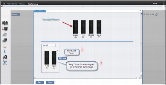
Figure 5-64 Creating a cluster family
Figure 5-65 shows an example of a cluster family configuration.
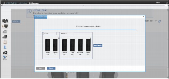
Figure 5-65 Cluster families
|
Important: Each cluster family needs to contain at least one cluster.
|
5.4.7 TS7720 cache thresholds and removal policies
This topic describes the boundaries (thresholds) of free cache space in a disk-only TS7720 Virtualization Engine, and the policies that can be used to manage available (active) cache capacity in a grid configuration.
Cache thresholds for a TS7720 cluster
A disk-only TS7720 Virtualization Engine does not attach to a physical back-end library. All virtual volumes are stored in the cache. There are three thresholds that define the active cache capacity in a TS7720 Virtualization Engine and determine the state of the cache as it relates to remaining free space. In ascending order of occurrence, the three thresholds are listed:
•Automatic Removal
The policy removes the oldest logical volumes from the TS7720 cache as long as a consistent copy exists elsewhere in the grid. This state occurs when the cache is 4 TB below the out-of-cache-resources threshold. In the automatic removal state, the TS7720 Virtualization Engine automatically removes volumes from the disk-only cache to prevent the cache from reaching its maximum capacity. This state is identical to the limited-free-cache-space-warning state unless the Temporary Removal Threshold is enabled.
You can disable automatic removal within any specific TS7720 cluster by using the following library request command:
LIBRARY REQUEST,CACHE,REMOVE,{ENABLE|DISABLE}
|
Note: The automatic removal function was introduced in R1.6 while the library request was introduced in R1.7.
|
So that a disaster recovery test can access all production host-written volumes, automatic removal is temporarily disabled while disaster recovery write protect is enabled on a disk-only cluster. When the write protect state is lifted, automatic removal returns to normal operation.
•Limited free cache space warning
This state occurs when there is less than 3 TB of free space left in the cache. After the cache passes this threshold and enters the limited-free-cache-space-warning state, write operations can use only an additional 2 TB before the out-of-cache-resources state is encountered. When a TS7720 cluster enters the limited-free-cache-space-warning state, it remains in this state until the amount of free space in the cache exceeds 3.5 TB. The following messages can be displayed on the MI during the limited-free-cache-space-warning state:
– HYDME0996W
– HYDME1200W
See the related information section in the TS7700 Customer Information Center for additional information about each of these messages:
|
Clarification: Host writes to the TS7720 cluster and inbound copies continue during this state.
|
•Out of cache resources
This state occurs when there is less than 1 TB of free space left in the cache. After the cache passes this threshold and enters the out-of-cache-resources state, it remains in this state until the amount of free space in the cache exceeds 3.5 TB. When a TS7720 cluster is in the out-of-cache-resources state, volumes on that cluster become read-only and one or more out-of-cache-resources messages are displayed on the MI. The following messages can display:
– HYDME0997W
– HYDME1133W
– HYDME1201W
See the related information section in the TS7700 Customer Information Center for additional information about each of these messages:
|
Clarification: New host allocations do not choose a TS7720 cluster in this state as a valid TVC candidate. New host allocations issued to a TS7720 cluster in this state choose a remote TVC instead. If all valid clusters are in this state or unable to accept mounts, the host allocations fail. Read mounts can choose the TS7720 cluster in this state, but modify and write operations fail. Copies inbound to this TS7720 cluster are queued as Deferred until the TS7720 cluster exits this state.
|
Table 5-3 displays the start and stop thresholds for each of the active cache capacity states defined.
Table 5-3 Active cache capacity state thresholds
|
State
|
Enter state (free space available)
|
Exit state (free space available)
|
Host message displayed
|
|
Automatic removal
|
< 4 TB
|
> 3.5 TB
|
CBR3750I when automatic removal begins
|
|
Limited free cache space warning
|
< 3 TB
|
> 3.5 TB
|
CBR3792E upon entering state
CBR3793I upon exiting state
|
|
Out of cache resources
|
< 1 TB
|
> 3.5 TB
|
CBR3794A upon entering state
CBR3795I upon exiting state
|
|
Temporary removal1
|
< (X = 1 TB)2
|
> (X + 1.5 TB)b
|
Console message
|
1 When enabled
2 Where X is the value set by the Tape Volume Cache window on the specific cluster.
The Removal policy is set by using the Storage Class window on the TS7720 MI. Figure 5-66 shows several definitions in place.

Figure 5-66 Storage Classes in TS7720 with removal policies
To add or change an existing Storage Class, select the appropriate action in the drop-down menu and click Go. See Figure 5-67 on page 277.

Figure 5-67 Defining a new Storage Class with TS7720
Removal Threshold
The Removal Threshold is used to prevent a cache overrun condition in a TS7720 cluster that is configured as part of a grid. By default, it is a 4 TB value (3 TB fixed, plus 1 TB) that, when taken with the amount of used cache, defines the upper limit of a TS7720 cache size. Above this threshold, logical volumes begin to be removed from a TS7720 cache.
|
Logical volumes are only removed if there is another consistent copy within the grid.
|
Logical volumes are removed from a TS7720 cache in this order:
1. Volumes in scratch (Fast Ready) categories
2. Private volumes least recently used, using the enhanced Removal policy definitions
After removal begins, the TS7720 Virtualization Engine continues to remove logical volumes until the Stop Threshold is met. The Stop Threshold is a value that is the Removal Threshold minus 500 GB.
A particular logical volume cannot be removed from a TS7720 cache until the TS7720 Virtualization Engine verifies that a consistent copy exists on a peer cluster. If a peer cluster is not available, or a volume copy has not yet completed, the logical volume is not a candidate for removal until the appropriate number of copies can be verified at a later time.
|
Tip: This field is only visible if the selected cluster is a TS7720 Virtualization Engine in a grid configuration.
|
Temporary Removal Threshold
The Temporary Removal Threshold lowers the default Removal Threshold to a value lower than the Stop Threshold in anticipation of a service mode event.
Logical volumes might need to be removed before one or more clusters enter service mode. When a cluster in the grid enters service mode, remaining clusters can lose their ability to make or validate volume copies, preventing the removal of an adequate number of logical volumes. This scenario can quickly lead to the TS7720 cache reaching its maximum capacity.
The lower threshold creates additional free cache space, which allows the TS7720 Virtualization Engine to accept any host requests or copies during the service outage without reaching its maximum cache capacity.
The Temporary Removal Threshold value must be equal to or greater than the expected amount of compressed host workload written, copied, or both to the TS7720 Virtualization Engine during the service outage. The default Temporary Removal Threshold is 4 TB, which provides 5 TB (4 TB plus 1 TB) of existing free space. You can lower the threshold to any value between 2 TB and full capacity minus 2 TB.
All TS7720 clusters in the grid that remain available automatically lower their Removal Thresholds to the Temporary Removal Threshold value defined for each. Each TS7720 cluster can use a different Temporary Removal Threshold. The default Temporary Removal Threshold value is 4 TB or an additional 1 TB more data than the default removal threshold of 3 TB. Each TS7720 cluster will use its defined value until any cluster in the grid enters service mode or the temporary removal process is canceled. The cluster that is initiating the temporary removal process will not lower its own removal threshold during this process.
Removal policy settings can be configured by using the TS7720 Temporary Removal Threshold option on the Actions menu available on the Grid Summary page of the TS7700 Virtualization Engine MI. Figure 5-68 shows the TS7720 Temporary Removal Threshold mode window.

Figure 5-68 Setting Temporary Remove Threshold in a TS7720
The TS7720 Temporary Removal Threshold mode window includes these options:
•Enable Temporary Thresholds
Check this box and click OK to start the pre-removal process. Clear this box and click OK to abandon a current pre-removal process.
•Cluster to be serviced
Select from this drop-down menu the cluster that will be put into service mode. The pre-removal process is started on this cluster.
|
Note: This process does not initiate Service Prep mode.
|
If the cluster selected from this drop-down menu is a TS7720 cluster, the cluster is disabled in the TS7720 List since the Temporary Removal Threshold will not be lowered on this cluster.
•TS7720 List
This area of the window contains each TS7720 cluster in the grid and a text field to set the temporary removal threshold for that cluster.
5.4.8 Backup and restore construct definitions
Using the MI, you can back up and restore scratch (Fast Ready) categories, Physical Volume Pools, and also all construct definitions, as shown in Figure 5-69.

Figure 5-69 TS7740 Virtualization Engine Backup Settings
|
Fast Path: See Chapter 9, “Operation” on page 413 for complete details of this window.
|
5.4.9 Data management settings (TS7740 Virtualization Engine)
The following settings for the TS7740 Virtualization Engine are optional. Your IBM SSR configures these settings during the installation of the TS7740 Virtualization Engine, or at a later time through the TS7740 Virtualization Engine SMIT menu. The following data management settings are valid:
•Copy Files Preferenced to Reside in Cache
•Recalls Preferenced for Cache Removal
Copy Files Preferenced to Reside in Cache
Normally, the TVCs in both TS7740 Virtualization Engines in a multicluster grid are managed as one TVC to increase the likelihood that a needed volume will be in cache. By default, the volume on the TS7740 Virtualization Engine selected for I/O operations is preferred to stay in cache on that TS7740 Virtualization Engine. The copy made on the other TS7740 Virtualization Engine is preferred to be removed from cache:
•Preferred to stay in cache means that when space is needed for new volumes, the oldest volumes are removed first. This algorithm is called the least recently used (LRU) algorithm. This is also referred to as Preference Group 1 (PG1).
•Preferred to be removed from cache means that when space is needed for new volumes, the largest volumes are removed first, regardless of when they were written to the cache. This is also referred to as Preference Group 0 (PG0).
For a TS7740 Virtualization Engine running in a dual production multicluster grid configuration, both TS7740 Virtualization Engines are selected as the I/O TVCs and will have the original volumes (newly created or modified) preferred in cache. The copies to the other TS7740 Virtualization Engine will be preferred to be removed from cache. The result is that each TS7740 Virtualization Engine TVC is filled with unique, newly created or modified volumes, therefore roughly doubling the amount of cache seen by the host.
For a TS7740 Virtualization Engine running in a multicluster grid configuration used for business continuance, particularly when all I/O is preferenced to the local TVC, this default management method might not be desired. If the remote site of the multicluster grid is used for recovery, the recovery time is minimized by having most of the needed volumes already in cache. What is really needed is to have the most recent copy volumes remain in the cache, not being preferred out of cache.
Based on your requirements, your IBM SSR can set or modify this control through the TS7740 Virtualization Engine SMIT menu for the remote TS7740 Virtualization Engine:
•The default is off.
•When set to off, copy files are managed as Preference Group 0 volumes (prefer out of cache first by largest size).
•When set to on, copy files are managed based on the Storage Class construct definition.
Recalls Preferenced for Cache Removal
Normally, a volume recalled into cache is managed as though it were newly created or modified because it resides in the TS7740 Virtualization Engine selected for I/O operations on the volume. A recalled volume will displace other volumes in cache.
If the remote TS7740 Virtualization Engine is used for recovery, the recovery time is minimized by having most of the needed volumes in cache. However, it is not likely that all of the volumes to restore will be resident in the cache and that some amount of recalls will be required. Unless you can explicitly control the sequence of volumes to be restored, it is likely that recalled volumes will displace cached volumes that have not yet been restored from, resulting in further recalls at a later time in the recovery process.
After a restore has completed from a recalled volume, that volume is no longer needed, and these volumes must be removed from the cache after they have been accessed so that they minimally displace other volumes in the cache.
Based on your requirements, the IBM SSR can set or modify this control through the TS7700 Virtualization Engine SMIT menu of the remote TS7740 Virtualization Engine:
•When off, which is the default, recalls are managed as Preference Group 1 volumes (LRU).
•When on, recalls are managed as Preference Group 0 volumes (prefer out of cache first by largest size).
This control is independent of and not affected by cache management controlled through the Storage Class SMS construct. Storage Class cache management affects only how the volume is managed in the I/O TVC.
5.5 Implementing Outboard Policy Management for non-z/OS hosts
Outboard Policy Management and its constructs are exploited only in DFSMS host environments where OAM has knowledge of the construct names and dynamically assigns and resets them. z/VM, z/VSE, TPF, z/TPF, and other hosts do not have knowledge of the construct names and therefore cannot change them. In addition, non-z/OS hosts use multiple Library Manager (LM) categories for scratch volumes and therefore can use multiple logical scratch pools on the Library Manager, as shown in Table 5-4.
Table 5-4 Scratch pools and Library Manager volume categories
|
Host software
|
Library Manager
scratch categories |
Number of
scratch pools |
Library Manager private categories
|
|
VM (+ VM/VSE)
|
X’0080’ - X’008F’
|
16
|
X’FFFF’
|
|
Basic Tape Library Support (BTLS)
|
X’0FF2’ - X’0FF8’, X’0FFF’
|
8
|
X’FFFF’
|
|
Native VSE
|
X’00A0’ - X’00BF’
|
32
|
X’FFFF’
|
|
Clarification: In a Transaction Processing Facility (TPF) environment, manipulation of construct names for volumes can occur when they are moved from scratch through a user exit. The user exit allows the construct names and clone VOLSER to be altered. If the exit is not implemented, TPF does not alter the construct names.
TPF use of categories is flexible. TPF allows each drive to be assigned a scratch category. Relating to private categories, each TPF has its own category to which volumes are assigned when they are mounted.
For more information about this topic, see the zTPF Information Center:
|
Because the hosts do not know about constructs, they ignore static construct assignment, and the assignment is kept even when the logical volume is returned to scratch. Static assignment means that at the insert time of logical volumes, they are assigned construct names, also. Construct names can also be assigned later at any time.
|
Tip: In a z/OS environment, OAM controls the construct assignment and will reset any static assignment made before using the TS7700 Virtualization Engine MI. Construct assignments are also reset to blank when a logical volume is returned to scratch.
|
To implement Outboard Policy Management for non-z/OS hosts attached to a TS7700 Virtualization Engine, perform the following steps:
1. Define your pools and constructs.
2. Insert your logical volumes into groups through the TS7700 Virtualization Engine MI, as described in “Inserting logical virtual volumes” on page 259. You can assign the required static construct names during the insertion as shown at the bottom part of the window in Figure 5-70.
On the left side of the MI, click Virtual → Virtual Volumes → Insert Virtual Volumes. The window in Figure 5-70 opens. Use the window to insert virtual volumes. Select the Set Constructs check box and type the construct names.
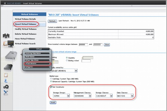
Figure 5-70 Insert logical volumes by assigning static construct names
3. If you want to modify existing VOLSER ranges and assign the required static construct names to the logical volume ranges through the “change existing logical volume” function, select Logical Volumes → Modify Logical Volumes to open the window shown in Figure 5-71. Use this window to change existing logical volumes.
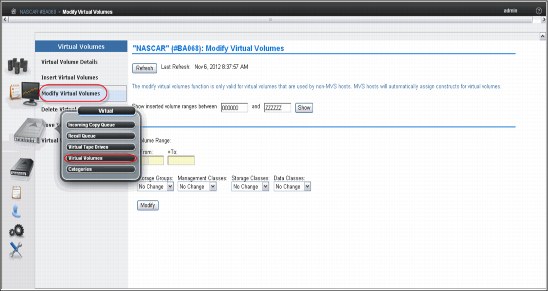
Figure 5-71 Modify logical volumes used by non-z/OS hosts
Define groups of logical volumes with the same construct names assigned and, during insert processing, direct them to separate volume categories so that all volumes in one LM volume category have identical constructs assigned.
Host control is given through the use of the appropriate scratch pool. By requesting a scratch mount from a specific scratch category, the actions defined for the constructs assigned to the logical volumes in this category are executed at the Rewind Unload of the logical volume.
1 The server address value in the Primary or Alternate Server URL can be an IP address or DNS address. Valid IP formats include the following formats:
- IPv4: 32 bits. Four decimal numbers ranging from 0 to 255, separated by periods, for example, 12.345.678.
- IPv6: 128-bit hexadecimal value enclosed by brackets, separated into 16-bit field by colons, for example, [1234:9abc:0::1:cdef:8]. Note that leading 0s can be omitted. A double colon (::) means a field of 0s (:0000:).
..................Content has been hidden....................
You can't read the all page of ebook, please click here login for view all page.