

Operation
This chapter describes operational considerations and usage guidelines unique to the IBM Virtualization Engine TS7700. For general guidance about how to operate the IBM System Storage TS3500 Tape Library, see the following publications:
•IBM TS3500 Tape Library with System z Attachment A Practical Guide to Enterprise Tape Drives and TS3500 Tape Automation, SG24-6789
•z/OS Object Access Method Planning, Installation and Storage Administration Guide for Tape Libraries, SC35-0427
This chapter provides information about how to operate the TS7700 Virtualization Engine by covering the following main topics:
•User interfaces
•IBM Virtualization Engine TS7700 MI
•System-managed tape
•Basic operations
•Tape cartridge management
•Managing logical volumes
•Messages and displays
•Recovery scenarios
•IBM Virtualization Engine TS7720 considerations
This chapter also includes information about these topics:
9.1 User interfaces
To successfully operate your TS7700 Virtualization Engine, you must understand its concepts and components. This chapter combines the components and functions of the TS7700 Virtualization Engine into two groups:
•The logical view
•The physical view
Each component and each function belong to only one view.
The logical view is named the host view. From the host allocation point of view, there is only one library, called the composite library. A composite library can have up to 1536 virtual addresses for tape mounts (considering a six-cluster grid). The logical view includes virtual volumes and virtual tape drives.
The host is only aware of the existence of the underlying physical libraries because they are defined through Interactive Storage Management Facility (ISMF) in a z/OS environment. The term distributed library is used to denote the physical libraries and TS7700 Virtualization Engine components that are part of one cluster of the multicluster grid configuration. The physical view is the hardware view that deals with the hardware components of a stand-alone cluster or a multicluster grid configuration. In a TS7740 Virtualization Engine, it includes the TS3500 Tape Libraries and 3592 J1A, TS1120, TS1130, or TS1140 tape drives.
The following operator interfaces for providing information about the TS7700 Virtualization Engine are available:
•Object access method (OAM) commands are available at the host operator console. These commands provide information regarding the TS7700 Virtualization Engine in stand-alone and grid environments. This information represents the host view of the components within the TS7700 Virtualization Engine. Other z/OS commands can be used against the virtual addresses. These commands are not aware that the 3490E addresses are part of a TS7700 Virtualization Engine configuration.
•Web-based management functions are available through web-based user interfaces:
– You can access the web interfaces with the browsers:
• Microsoft Internet Explorer Version 8.x or 9.x
• Mozilla Firefox 6.x, 7.x, 10.x, 10.0.x Extended Support Release (ESR), or 13.x
Enable cookies and disable the browser’s function of blocking pop-up windows.
– There are two management functions available for tape library management:
• The TS3500 Tape Library Specialist allows for management (configuration and status) of the TS3500 Library.
• The TS7700 Virtualization Engine management interface (MI) is used to perform all TS7700 Virtualization Engine-related configuration, setup, and monitoring actions.
•Call Home Interface: This interface is activated on the TS3000 System Console (TSSC) and allows for Electronic Customer Care (ECC) by IBM System Support. Alerts can be sent out to IBM RETAIN® systems and the IBM service support representative (SSR) can connect through the TSSC to the TS7700 Virtualization Engine and the TS3500 Tape Library.
This chapter focuses on the interfaces related to the operation of the TS7700 Virtualization Engine. For more information about tape library operator windows, see the IBM System Storage TS3500 Tape Library Operator Guide, GA32-0560, and IBM TS3500 Tape Library with System z Attachment A Practical Guide to Enterprise Tape Drives and TS3500 Tape Automation, SG24-6789.
9.1.1 TS3500 Tape Library Specialist
The IBM System Storage TS3500 Tape Library Specialist (TS3500 Tape Library web specialist) interface, in conjunction with the TS7740 Virtualization Engine interface, allows you to perform many library functions from the web.
Figure 9-2 on page 416 shows the TS3500 Tape Library Specialist welcome window with the System Summary, where you can choose to view the status of a complete library.
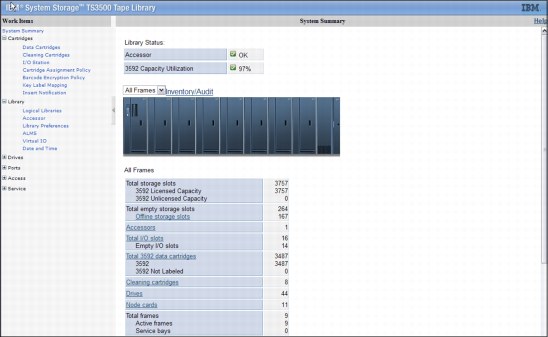
Figure 9-1 TS3500 Tape Library Specialist welcome window
Figure 9-2 on page 416 shows a flowchart of the functions that are available depending on the configuration of your TS3500 Tape Library.

Figure 9-2 TS3500 Tape Library Specialist functions
The TS3500 windows are mainly used during the hardware installation phase of the TS7740 Virtualization Engine. The activities involved in installation are described in 5.2, “TS3500 Tape Library definitions (TS7740 Virtualization Engine)” on page 192.
9.1.2 Call Home and Electronic Customer Care
The tape subsystem components include several external interfaces that are not directly associated with data paths. Instead, these interfaces are associated with system control, service, and status information. They support customer interaction and feedback, and attachment to IBM remote support infrastructure for product service and support. These interfaces and facilities are part of the IBM System Storage Data Protection and Retention (DP&R) storage system. The main objective of this mechanism is to provide a safe and efficient way for the System Call Home (Outbound) as well as Remote Support (Inbound) connectivity capabilities.
See the document “IBM Data Protection & Retention System Connectivity and Security”, WP100704, for a complete description of the connectivity mechanism and related security aspects:
The Call Home function generates a service alert automatically when a problem occurs with one of the following components:
•TS3500 Tape Library
•3592 tape controllers models J70, C06, and C07
•TS7700 Virtualization Engine
Error information is transmitted to the IBM System Storage TS3000 System Console for service, and then to the IBM Support Center for problem evaluation. The IBM Support Center can dispatch an IBM SSR to the client installation. Call Home can send the service alert to a pager service to notify multiple people, including the operator. The SSR can deactivate the function through service menus, if required.
Electronic Customer Care
This section provides an overview of the communication path between your purchased subsystems and IBM support. This method has been used for Call Home since the introduction of the TotalStorage System Console (TSSC). It was previously known as the TotalStorage Master Console (TSMC).
The TSSC uses analog phone lines and a modem or a broadband connection to connect to the IBM Remote Technical Assistance Information Network (RETAIN). The code running in RETAIN then decides what to do with the information. A problem management record (PMR) will be opened in a problem. After the PMR is created, RETAIN automatically consults with the IBM Knowledge-Based Systems (RKBS) to add information pertinent to the reported problem. Finally, in the case where RETAIN detects that the call home is a data package, the data is forwarded to catchers that move the data to an IBM internal server called the Distributed File Service cell (DFS cell). From there, it is pulled into the IBM Tape Call Home Database.
Figure 9-3 on page 418 describes the Electronic Customer Care Call Home function. There are three security zones:
•The Red Zone is defined as your data center. This zone is where the IBM storage subsystem and the TSSC reside.
•The Yellow Zone is defined as the open Internet. This is open to all outside communication.
•The Blue Zone is defined as IBM Support. This sits inside the IBM intranet and is only accessible to IBM-authenticated users.
In Electronic Customer Care, the TSSC will use either a modem connection or a broadband connection to connect to an Electronic Customer Care gateway located in the Yellow Zone. This is a server managed by IBM that is used as a relay for IBM Support information. This gateway then forwards the information to the Inter Enterprise Process Directory (IEPD). IEPD is located within IBM Support in the Blue Zone. IEPD then checks the problem report that has been submitted and monitors from which system the report has come. The system’s credentials are then checked to ensure that a valid support contract exists. If the credentials pass for this system, it will consult the Technical Services Knowledge Base System (TSKBS) for known information to add to the problem report. The problem report will then be used to open a PMR in IBM RETAIN.
In a data call home, the data is sent from the same TSSC connection to a server managed by IBM that is located in the Yellow Zone, known as Testcase. Dumpers monitor this server for new information. When they see this new information, they move the data package to DFS space where it gets pulled into the RMSS Call Home Database.
Initial ECC handshaking communication uses HTTP communication. After initial handshaking, all information is sent using secure HTTPS communication. Because all traffic is outbound in nature and only uses the HTTP and HTTPS ports, connectivity works through most firewalls without any additional firewall rules.
Problem reporting communication is then sent to IEPD, which consults TSKBS for the systems listed, and opens a PMR in RETAIN. Of course, all of these details are for informational purposes only. After initial setup, these details are used in the background without the knowledge of the user.
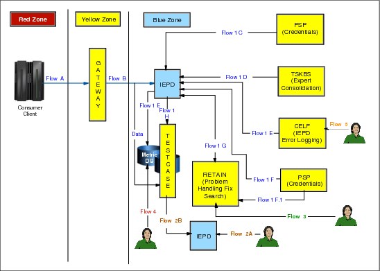
Figure 9-3 Electronic Customer Care
Inbound connections by IBM service personnel can be through a dial-in modem connection or over a broadband connection.
|
Note: All inbound connections are subject to the security policies and standards defined by the client. When a Storage Authentication Service or direct Lightweight Directory Access Protocol (LDAP) policy is enabled for a cluster, service personnel - local or remote - are required to use the LDAP-defined service login.
Important: Be sure that an account has been created to be used by service personnel before enabling storage authentication or direct LDAP policies.
|
The outbound communication associated with ECC call home can be through an Ethernet connection, a modem, or both in the form of a failover setup. The local subnet LAN connection between the TSSC and the attached subsystems remains the same. It is still isolated without any outside access.
ECC adds another Ethernet connection to the TSSC, bringing the total number to three. These connections are labeled:
•The External Ethernet Connection, which is the ECC Interface
•The Grid Ethernet Connection, which is used for the TS7740 Virtualization Engine Autonomic Ownership Takeover Manager (AOTM)
•The Internal Ethernet Connection, used for the local attached subsystem’s subnet
All of these connections are set up using the Console Configuration Utility User Interface located on the TSSC.
Starting from TS7700 Virtualization Engine R2.0, the Call Home events can be found in the MI window’s Health Monitoring - Events. It will show whether the event initiated a Call Home.
Tivoli Assist On-site
Enhanced support capabilities include the introduction of Tivoli Assist On-site (AOS) to expand maintenance capabilities. This is a service function managed by an IBM SSR or by the client through the AOS customer interface. AOS is a tool that allows an authenticated session for remote TSSC desktop connections over an external broadband Ethernet adapter. An AOS session allows IBM remote support center representatives to troubleshoot issues with the machine.
AOS uses the same network as broadband call home, and will work on either HTTP or HTTPS. The AOS function is disabled, by default. When enabled, the AOS can be configured to run in either attended or unattended modes:
•Attended mode requires that the AOS session be initiated at the TSSC associated with the target TS7700 Virtualization Engine. This will require physical access by the IBM SSR to the TSSC or the client through the customer interface.
•Unattended mode, also called Lights Out mode, allows a remote support session to be established without manual intervention at the TSSC associated with the target TS7700 Virtualization Engine.
All AOS connections are outbound. In unattended mode, the session is established by periodically connecting to regional AOS relay servers to determine whether remote access is needed. If access has been requested, AOS will authenticate and establish the connection, allowing a remote desktop access to the TSSC.
|
Note: Remember that all authentications are subject to the Authentication policy in effect. See the information under 9.2.8, “The Access icon” on page 526.
|
9.2 TS7700 Virtualization Engine Management Interface
The TS7700 Virtualization Engine management interface (MI) is the primary interface to monitor and administer the TS7700 Virtualization Engine.
|
Tip: Starting with Release 3.0, a new graphical user interface (GUI) has been implemented. It gives the TS7700 MI a similar look and feel to the XIV and DS8000 management interfaces.
|
9.2.1 Connecting to the management interface
To connect to the TS7700 Virtualization Engine MI, perform the following steps:
1. The TS7700 Virtualization Engine must first be installed and configured.
2. In the address field of a supported web browser, enter http://x.x.x.x/Console (where x.x.x.x is the virtual IP address that was assigned during installation). Press Enter or click Go in your web browser.
|
Tip: The following web browsers are supported currently:
•Firefox 6.0, 7.0, 10.0, 10.0 ESR, and 13.0
•Internet Explorer 8 and 9
|
3. The virtual IP is one of three IP addresses given during installation. See 4.2.2, “TCP/IP configuration considerations” on page 142. If you want to access a specific cluster, the cluster must be specified when the IP address is entered as shown in Example 9-1 where Cluster 0 is accessed directly.
Example 9-1 IP address to connect to Cluster 0 in a grid
http://x.x.x.x/0/Console
4. If you are using your own name server, where you can associate a name with the virtual IP address, you can use the name instead of the hardcoded address for reaching the MI.
5. The login page for the MI displays as shown in Figure 9-4. Enter the default login name as admin and the default password as admin.

Figure 9-4 TS7700 Virtualization Engine MI login
After entering your password, you see the first web page presented by the MI, the Virtualization Engine Grid Summary, as shown in Figure 9-5 on page 421.
After security policies have been implemented locally at the TS7700 Virtualization Engine cluster or through the use of centralized role-base access control (RBAC), a unique user identifier and password can be assigned by the administrator. The user profile can be modified to only provide functions applicable to the role of the user. All users might not have access to the same functions or views through the MI. See 9.2.8, “The Access icon” on page 526 for more details.
Figure 9-5 on page 421 shows a visual summary of the TS7700 Virtualization Engine Grid. It shows a five-cluster grid, the components, and health status. The composite library is depicted as a data center, with all members of the grid on the raised floor.

Figure 9-5 MI Virtualization Engine Grid Summary
Each cluster is represented by an image of the TS7700 Virtualization Engine, displaying the cluster’s nickname and ID, as well as the composite library name and Library ID.
The health of the system is checked and updated automatically at times determined by the TS7700 Virtualization Engine. Data loaded on the page is not in real time. The Last Refresh field, in the upper-right corner, reports the date and time that the displayed data was retrieved from the TS7700 Virtualization Engine. To populate the summary with an updated health status, click the Refresh icon near the Last Refresh field in the upper-right corner of Figure 9-5.
The health status of each cluster is indicated by a status sign affixed to its icon. The legend explains the meaning of each status sign. To obtain additional information about a specific cluster, click that component’s icon.
Library control with TS7700 Virtualization Engine Management Interface
The TS770 MI also controls the library operations. In environments where the tape configuration is separated from the LAN-attached hosts or web clients by a firewall, these are the only ports that must be opened on the firewall. All others can be closed. See Table 9-1 on page 422 for more information.
Table 9-1 Network interface firewall
|
Function
|
Port
|
Direction (from library)
|
Protocol
|
|
TS3500 Tape Library Specialist
|
80
|
Inbound
|
TCP/IP
|
|
Simple Network Management Protocol (SNMP) traps
|
161/162
|
Bidirectional
|
User Datagram Protocol (UDP)/IP
|
|
Encryption Key Manager
|
1443
|
Outbound
|
Secure Sockets Layer (SSL)
|
|
Encryption Key Manager
|
3801
|
Outbound
|
TCP/IP
|
For a description of all ports needed for components within the grid, see 4.2.2, “TCP/IP configuration considerations” on page 142.
9.2.2 Using the TS7700 Management Interface
This topic describes how to use the IBM Virtualization Engine TS7700 MI and its common page and table components.
|
Important: In order to support Japanese input, a Japanese front-end processor needs to be installed on the computer where a web browser is running the MI.
|
Login
Each cluster in a grid uses its own login page. This is the first page displayed when you enter the cluster URL in your browser address field. The login page displays the name and number of the cluster to be accessed. After you log in to a cluster, you can access other clusters in the same grid.
Navigating between pages
You can move between MI pages using the iconic navigation, by clicking active links on a page or on the banner, or by launching a menu option.
|
Important: You cannot use the Back or Forward buttons or the Go Back or Go Forward options in your browser to navigate between MI pages.
|
Banner
The banner is common to all pages of the MI. You can use banner elements to navigate to other clusters in the grid, perform some user tasks, and locate additional information about the MI.
Table 9-2 on page 423 lists actions that can be performed by using banner elements.
Table 9-2 Actions that can be performed by using banner elements
|
To perform this task
|
Action
|
|
|
Return to the main system page from any other page of the MI
|
Click the home icon in the breadcrumb navigation displayed on the left side of the banner. The main system page is the Cluster Summary if the accessing cluster is a stand-alone cluster, or the Grid Summary if the cluster is part of a grid.
|
|
|
View the same page for a different cluster in a grid
|
• Hover over the cluster nickname in the breadcrumb navigation.
•Click a cluster from the drop-down menu.
|
|
|
Log out of the MI
|
Select User Name → Log Out.
|
|
|
Change the password associated with the User Name
|
Select User Name → Change Password.
Password rules:
•Must be at least six, but no more than 16 alphanumeric characters
•Must contain at least one number
•First and last characters cannot be numbers
•Cannot contain the User Name
Note: This menu option is available only if the following conditions are true:
•The user has permission to change passwords.
•Local Authentication Policy is enabled on the accessing cluster.
|
|
|
View help for the MI page
|
Select TS7700 Learning &Tutorials.
|
|
|
Launch the TS7700 Customer Information Center
|
Select Information Center.
|
|
|
View system hardware and software information for this cluster
|
Select About.
|
|
Status and event indicators
Status and alert indicators occur at the bottom of each MI page. These indicators provide a quick status check for important cluster and grid properties. Grid indicators provide information for the entire grid. These indicators are displayed on the left and right corners of the page footer and include tasks and events.
All cluster indicators provide information only for the accessing cluster and are displayed only on MI pages that have a cluster scope. These three indicators occur in the middle of the page footer and include information:
•Physical Cache
•Copy Queues
•Health Status
Table 9-3 on page 424 describes the behavior of health and status icons displayed at the bottom of the MI pages.
Table 9-3 Behavior of health and status icons at the bottom of the MI
|
Indicator
|
Description
|
|||
|
Tasks
|
A clipboard icon containing a check mark, displayed in lower-left corner of the page. Use to determine any running or recently completed long-running tasks.
Note: If the accessing cluster is a stand-alone cluster, any tasks shown are for that cluster only. If the accessing cluster is part of a grid, the tasks shown are for the entire grid.
A number inside a blue circle is displayed on the clipboard to indicate the total number of running or recently completed tasks:
•Hover over the number of tasks to display the three most recently started tasks and their status.
•Click a task to open the Tasks page.
When a new task starts, completes, or fails, this indicator displays a notification for approximately two seconds.
|
|||
|
Events
|
A clipboard icon containing an X, displayed in lower-right corner of the page. Use to determine active critical and warning events for the grid.
Note: This indicator is not displayed if the accessing cluster is a stand-alone cluster.
A number inside a yellow circle is displayed on the clipboard to indicate the total number of Warning or Degraded events on the grid.
A number inside a red circle is displayed on the clipboard to indicate the total number of Critical or Failed events on the grid:
•Hover over the number of alerts to display the three highest severity events on the grid.
•Click an event to open the Events page.
When a new alert arrives, this indicator displays a notification for approximately two seconds.
|
|||
|
Physical Cache
|
Displays physical cache capacity for the accessing cluster using this color scheme:
•Green: Cache used
•Light green: Available cache
•Yellow: Low cache level (within 3 TB cache full level), accompanied by warning icon. This status is shown only on a TS7720 Cluster, since a low cache level is normal for TS7740 Cluster operations.
•Red: Out of cache level (within 1 TB cache full level), accompanied by failure icon. This status is shown only on a TS7720 Cluster, since a low cache level is normal for TS7740 Cluster operations.
Clicking the Physical Cache indicator will open up the Cache Utilization page.
Hover over the Tape Volume Cache icon to display additional cache information.
|
|||
|
Copy Queues
|
Displays incoming copy queue information for the accessing cluster using this color scheme:
•Gray: Queue is empty.
Note: Since copies occur between clusters, this status is shown when the accessing cluster is a stand-alone cluster.
•Blue: Immediate, Deferred, or Family-deferred copies exist in the queue.
•Yellow: Synchronous-deferred, Immediate-deferred, or copy refresh copies exist in the queue.
•Hover over the indicator to display the three largest queues, ordered by importance.
•Click a queue item to open the Copy Queue page.
|
|||
|
Health Status
|
Displays health status of the accessing cluster and any critical or warning events on the cluster. The following color scheme is used:
•Green: Normal, no issues exist on the cluster.
•Yellow: A warning or degraded event exists.
•Orange: A failed event exists.
•Red: An unrecoverable event exists.
If multiple events exist, the indicator displays the color corresponding to the most severe active event:
•Hover over the indicator to display the top three highest severity events.
•Click an event to open the Events page.
|
|||
Different tables in the MI contain a number of features that allow for various filtering, sorting, and changing of the display options. Depending on the table construction, one or more of these features is available. Table 9-4 describes features of tables that can be found throughout the MI.
Table 9-4 Feature of tables that can be found on the TS7700 MI
|
To perform this task
|
Actions
|
|||
|
Select options specific to the table
|
Click Select Action menu.
|
|||
|
Sort table results
|
Click Select Action → Table Actions → Edit Sort or
click Edit Sort.
|
|||
|
Clear table sort
|
Click Select Action → Table Actions → Clear All Sorts or
click Clear All Sorts or click Reset.
|
|||
|
Show or hide filter options; apply filter conditions
|
Click Select Action → Table Actions → Show/Hide Filter Row or
click Show/Hide Filter Row.
Refine by entering a Condition or Text values.
|
|||
|
Clear filters
|
Click Select Action → Table Actions → Clear All Filters or
click Clear All Filters.
|
|||
|
Display or hide columns
|
1. Click column icon on last table column.
2. In the pop-up list of column names, check columns to be displayed. Clear columns to be hidden.
3. Click Reset Table Preferences to undo changes.
Note: This icon is only visible in some new tables introduced with 8.30.0.xx microcode.
|
|||
|
Configure columns
|
Click Select Action → Table Actions → Configure Columns or
click Configure Columns.
|
|||
|
Resize a column
|
Hover over the right edge of the column header until the select arrow becomes a double-arrow resize pointer. When the resize pointer is shown, click and
hold the left mouse button and drag the cursor to the right or left. |
|||
|
Print a report of table data
|
Click Print Report.
|
|||
|
Saves a copy of the table data in a comma-separated value (.csv) file to a local directory
|
Click Download Spreadsheet.
|
|||
Fields containing a dash (-) instead of a value
If a field or table cell on the IBM Virtualization Engine TS7700 MI displays a dash (-) instead of a value, no value exists for that field or cell.
Accessing clusters with different code levels
In a TS7700 grid, separate clusters can have different MI code levels. You can access a remote cluster with a different code level from the local cluster through an MI operation. You are prompted to log in to the remote cluster or return back to the local MI. If you opt to log in to the remote cluster, you are redirected to the cluster login page.
|
Tip: The Compatibility View is not supported by the TS7700 Virtualization Engine. In the browser menu bar, clear Tools → Compatibility View.
|
Before explaining in detail the tasks that you can perform from the TS7700 Virtualization Engine MI, common page and table elements are described.
|
Note: To support Japanese input, a Japanese front-end processor needs to be installed on the computer where a web browser is accessing the MI.
|
Standard navigation elements
This section of the TS7700 Virtualization Engine MI provides you with functions to manage and monitor the health the TS7700 Virtualization Engine. Listed next are the expandable interface pages displayed on the left side of the MI Summary page. The exception is the systems interface page, which is displayed only when the cluster is part of a grid.
Systems icon This page shows the cluster members of the grid and grid-related functions.
Monitor icon This page gathers the events, tasks, and performance information regarding one cluster.
Light cartridge icon Information related to virtual volumes is available here.
Dark cartridge icon Information related to physical cartridges and the associated tape library are under this page.
Notepad icon In this page, you will find the constructs settings.
Blue man icon Under the Access icon, you will find all security-related settings.
Gear icon Cluster general settings, feature licenses, overrides, SNMP, selective device access control (SDAC), write protect mode, and backup and restore settings under the Gear icon.
Tool icon Ownership takeover mode, network diagnostics, data collection, and other repair/recovery-related activities are under this icon.
MI Navigation
Use this window (Figure 9-6) for a visual summary of the IBM Virtualization Engine TS7700 MI Navigation.
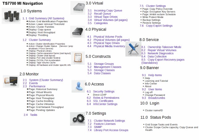
Figure 9-6 TS7700 Virtualization Engine MI Navigation
9.2.3 The Systems icon
The TS7700 Virtualization Engine MI pages gathered under the Systems icon can help to quickly identify a cluster or grid properties, as well as assess the cluster or grid “health” at a glance.
|
Tip: The Systems icon is only visible when the accessed TS7700 Cluster is part of a grid.
|
Grid Summary page
The Grid Summary panel is the first page displayed on the web interface when the IBM Virtualization Engine TS7700 is online. You can use this panel to quickly assess the health of all clusters in the grid and as a starting point to investigate cluster or network issues. This panel shows a summary view of the health of all clusters in the grid, including family associations, host throughput, and any incoming copy queue.
|
Note: If the accessing cluster is a stand-alone cluster, the Cluster Summary panel is shown upon login.
|
Table 9-5 describes available actions and displays that can be performed from the Grid Summary panel along with the procedure to accomplish it.
Table 9-5 Actions available from the Grid Summary panel
|
To perform this task
|
Action
|
|||
|
Investigate the details and health of a specific cluster
|
• Review any Health State icon shown on the lower-right corner of a cluster image.
•Hover over a cluster icon to display a description of its health state.
•Click a cluster icon to launch the Cluster Summary panel.
|
|||
|
Change the order of clusters displayed
|
Select Order by ID or Order by Family from the Actions menu.
|
|||
|
Show or hide cluster family relationships
|
Select or clear Show Families from the Actions menu.
|
|||
|
Change cluster family configurations
|
Select Cluster Families from the Actions menu.
|
|||
|
Change grid nickname or description
|
Select Modify Grid Identification from the Actions menu.
|
|||
|
Change temporary removal threshold settings
|
Select Temporary Removal Threshold from the Actions menu.
|
|||
|
Check host throughput values
|
Hover over a cluster image to display the Raw Host Throughput window. Click this window to launch the Host Throughput panel.
|
|||
|
Check copy queue status for a specific cluster
|
• When the copy queue bar is shown to the right of the cluster, review displayed queue levels and limits.
•Hover over the copy queue bar to display queue details in the Copy Queue window.
•Click the Copy Queue window to launch the Incoming Copy Queue panel.
|
|||
|
Identify throttling behavior for a specific TS7700 Cluster
|
Hover over any throttling notification bar displayed beneath the cluster name to display the Throttling Status window. Click the question mark (?) icon in the Throttling Status window to review possible causes and remedies for the throttling behavior.
|
|||
See Figure 9-7 on page 429 for an example of a Grid Summary panel, including the pop-up windows.
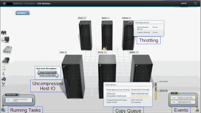
Figure 9-7 Grid Summary and pop-up windows
Actions menu
Use this menu to change the appearance of clusters on the Grid Summary panel or grid identification details. When the grid includes a TS7720 Virtualization Engine, you can also use this menu to change TS7720 Virtualization Engine removal threshold settings. See Figure 9-8 on page 430 for the Actions menu panel.
The following tasks are on this menu:
•Order by Cluster ID
Select this option to group clusters according to their cluster ID number. Ordered clusters are shown first from left to right, then front to back. Only one ordering option can be selected at a time.
|
Note: The number shown in parentheses in breadcrumb navigation and cluster labels is always the cluster ID.
|
•Order by Families
Select this option to group clusters according to their family association.
•Show Families
Select this option to show the defined families on the grid summary page. Cluster families are used to group clusters in the grid according to a common purpose.
•Cluster Families
Select this option to add, modify, or delete cluster families used in the grid.

Figure 9-8 Grid Summary page and Actions
Cluster Families window
Use the window shown in Figure 9-9 on page 431 to view information and perform actions related to TS7700 Virtualization Engine cluster families.

Figure 9-9 MI Add Cluster Families window
Data transfer speeds between TS7700 Virtualization Engine clusters sometimes vary. The cluster family configuration groups clusters so that microcode can optimize grid connection performance between the grouped clusters.
To view or modify cluster family settings, first verify that these permissions are granted to your assigned user role. If your user role includes cluster family permissions, select Modify to perform the following actions:
•Add a family: Click Add to create a new cluster family. A new cluster family placeholder is created to the right of any existing cluster families. Enter the name of the new cluster family in the active Name text box. Cluster family names must be one to eight characters in length and composed of Unicode characters. Each family name must be unique. Clusters are added to the new cluster family by relocating a cluster from the Unassigned Clusters area using the method described in the Move a cluster function, described next.
•Move a cluster: You can move one or more clusters, by drag and drop, between existing cluster families, to a new cluster family from the Unassigned Clusters area, or to the Unassigned Clusters area from an existing cluster family:
– Select a cluster: A selected cluster is identified by its highlighted border. Select a cluster from its resident cluster family or the Unassigned Clusters area by using one of these methods:
• Clicking the cluster with your mouse.
• Using the Spacebar key on your keyboard.
• Pressing and holding the Shift key while selecting clusters to select multiple clusters at one time.
• Pressing the Tab key on your keyboard to switch between clusters before selecting one.
– Move the selected cluster or clusters:
• Clicking and holding the mouse on the cluster and drag the selected cluster to the destination cluster family or the Unassigned Clusters area.
• Using the arrow keys on your keyboard to move the selected cluster or clusters right or left.
|
Restriction: An existing cluster family cannot be moved within the Cluster Families window.
|
•Delete a family: You can delete an existing cluster family. Click the X in the upper-right corner of the cluster family you want to delete. If the cluster family that you attempt to delete contains any clusters, a warning message is displayed. Click OK to delete the cluster family and return its clusters to the Unassigned Clusters area. Click Cancel to abandon the delete action and retain the selected cluster family.
•Save changes: Click Save to save any changes made to the Cluster Families window and return it to read-only mode.
|
Remember: Each cluster family must contain at least one cluster. If you attempt to save changes and a cluster family does not contain any clusters, an error message displays and the Cluster Families window remains in edit mode.
|
Grid Identification properties window
Use the window shown in Figure 9-10 on page 433 to view and alter identification properties for the TS7700 Virtualization Engine grid. This window can be used to distinguish the composite libraries correctly in the client environment.
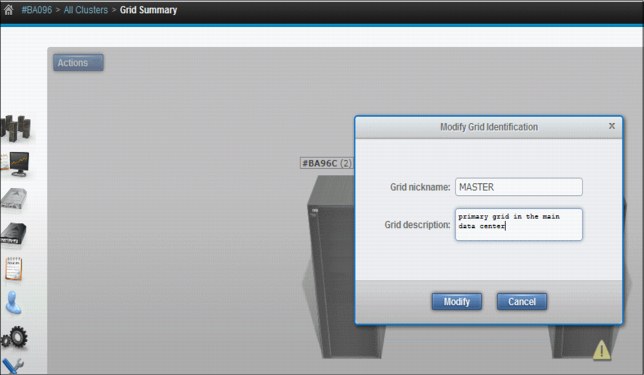
Figure 9-10 MI Grid Identification properties window
The following information, related to grid identification, is displayed. To change the grid identification properties, edit the available fields and click Modify. The following fields are available:
•Grid nickname: The grid nickname must be one to eight characters in length and composed of alphanumeric characters with no spaces. The characters @, ., -, and + are also allowed.
•Grid description: A short description of the grid. You can use up to 63 characters.
Lower removal threshold
Select TS7720 Temporary Removal Threshold from the Actions menu in the Grid summary view to lower the removal threshold for any TS7720 cluster in the grid.
For a TS7720 cluster in a grid where some clusters also attach to a physical library, you can use this option to lower the threshold at which virtual volumes are removed from cache. When the threshold is lowered, additional virtual volumes already copied to another cluster are removed, creating additional cache space for host operations. This is necessary to ensure that virtual volume copies can be made and validated before a service mode event.
Virtual volumes may need to be removed before one or more clusters enter service mode. When a cluster in the grid enters service mode, the remaining clusters can lose their ability to make or validate volume copies, preventing the removal of an adequate number of virtual volumes. This scenario can quickly lead to the TS7720 cache reaching its maximum capacity. The lower threshold creates additional free cache space, which allows the TS7720 Virtualization Engine to accept any host requests or copies during the service outage without reaching its maximum cache capacity.
The temporary removal threshold is used to temporarily establish a removal threshold that is lower than the default, or permanent, removal threshold. Figure 9-11 shows the TS7720 Temporary Removal Threshold panel.
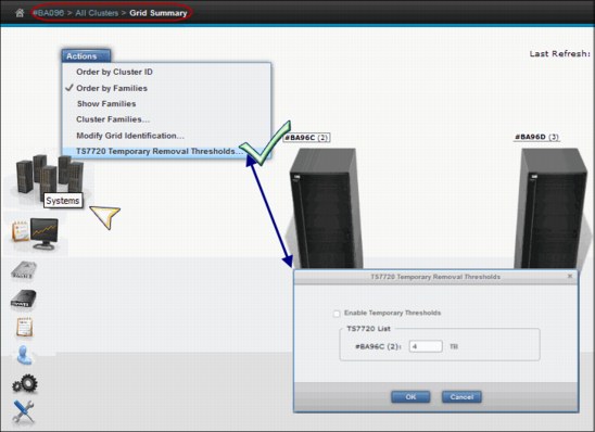
Figure 9-11 TS7720 Temporary Removal Threshold
Permanent removal threshold
The default, or permanent, removal threshold is used to prevent a cache overrun condition in a TS7720 cluster configured as part of a grid. It is a 4 TB (3 TB fixed, plus 1 TB) value that, when taken with the amount of used cache, defines the upper limit of a TS7720 cache size. Above this threshold, virtual volumes begin to be removed from a TS7720 cache. Virtual volumes are removed from a TS7720 cache in this order:
•Volumes in scratch (Fast Ready) categories
•Private volumes least recently used, using the enhanced Removal policy definitions
After removal begins, the TS7720 Virtualization Engine continues to remove virtual volumes until the stop threshold is met. The stop threshold is a value that is the removal threshold minus 500 GB.
A particular virtual volume cannot be removed from a TS7720 cache until the TS7720 Virtualization Engine verifies that a consistent copy exists on a peer cluster. If a peer cluster is not available, or a volume copy has not yet completed, the virtual volume is not a candidate for removal until the appropriate number of copies can be verified at a later time.
Temporary removal threshold
The temporary removal threshold lowers the default removal threshold to a value lower than the stop threshold in anticipation of a service mode event.
The Temporary Removal Threshold value must be equal to or greater than the expected amount of compressed host workload written, copied, or both to the TS7720 Virtualization Engine during the service outage. The temporary removal threshold is 4 TB, providing 5 TB (4 TB plus 1 TB) of free space exists, but you can lower the threshold to any value between
2 TB and full capacity minus 3 TB.
2 TB and full capacity minus 3 TB.
All TS7720 clusters in the grid that remain available automatically lower their removal thresholds to the temporary removal threshold value defined for each. Each TS7720 cluster may use a different temporary removal threshold. The default temporary removal threshold value is 4 TB or an additional 1 TB more data than the default removal threshold of 3 TB. Each TS7720 cluster will use its defined value until any cluster in the grid enters service mode or the temporary removal process is canceled. The cluster initiating the temporary removal process will not lower its own removal threshold during this process.
Details of the TS7720 Temporary Removal Threshold modal window are shown on Table 9-6.
Table 9-6 Elements displayed on the TS7720 temporary Removal Threshold modal window
|
Element
|
Description
|
|
|
Enable Temporary Thresholds
|
Check this box and click OK to start the pre-removal process. Clear this box and click OK to abandon a current pre-removal process.
|
|
|
Cluster to be serviced
|
Select from this drop-down menu the cluster that will be put into service mode. The pre-removal process is started on this cluster.
Note: This process does not initiate service prep mode.
If the cluster selected from this drop-down menu is a TS7720 Cluster, the cluster is disabled in the TS7720 List since the Temporary Removal Threshold will not be lowered on this cluster.
|
|
|
TS7720 List
|
This area of the modal window contains each TS7720 cluster in the grid and a text field to set the temporary removal threshold for that cluster.
|
|
Grid health and details
Use the main view of the Grid Summary panel to compare the details and health status of all clusters in the grid. The following status icons can be displayed on each cluster image in the Grid Summary panel. You can view additional information about the status by hovering over the icon with a mouse pointer. See Figure 9-37 on page 465 for the Warning or Degraded Status Icon and possible reasons for the icon.

Figure 9-12 Warning or Degraded status
Use the main view of the Grid Summary panel to compare the details and health status of all clusters in the grid. The following status icons can be displayed on each cluster image in the Grid Summary panel. You can view additional information about the status by hovering over the icon with a mouse pointer.
•Warning or Degraded, see Figure 9-12 for the icon and meaning.
•Failed, see Figure 9-13 on page 437 for the icon and meaning.
•Service, see Figure 9-13 on page 437 for the icon and meaning.
•Unknown, see Figure 9-13 on page 437 for the icon and meaning.
•Offline, see Figure 9-13 on page 437 for the icon and meaning.
•Event, see Figure 9-13 on page 437 for the icon and meaning.
Figure 9-13 on page 437 shows other status icons and meanings.

Figure 9-13 Other status icons for a Grid Summary or Cluster Summary panel
The main view of the grid summary panel displays all clusters in the grid. Click a cluster’s image to open the Cluster Summary panel for that cluster. Each cluster is labeled using either the Cluster Nickname (if defined) or Cluster ID (if no nickname is defined). Status icons can be displayed on each cluster image in the Grid Summary panel. You can view additional information about the status by hovering over the icon with a mouse pointer:
Last Refresh The time stamp for the last refresh is located on the upper-right side of the Grid Summary panel. It displays the time the health of the system was last checked and updated. Data shown is not in real time, but based on the automatic refresh determined by the TS7700 Virtualization Engine. To populate the summary with an updated health status, click the Refresh icon. This operation can take some time to complete.
Grid View The main view of the Grid Summary panel displays all clusters in the grid. Click a cluster’s image to open the Cluster Summary panel for that cluster.
Cluster Summary Each cluster is labeled using either the Cluster Nickname (if defined) or Cluster ID (if no nickname is defined). If a Cluster Nickname exists, the cluster label appears in the following manner:
Cluster Nickname (Cluster ID)
If no Cluster Nickname exists, the cluster label appears this way:
#Distributed Library Sequence Number (Cluster ID)
The cluster that was used to log in to the web interface is the accessing cluster and is identified by a surrounding border. If the Show Families option is enabled, a label displaying each cluster’s family is shown beneath the cluster label.
Raw Host Throughput
We show an example of a grid with both clusters throttling in Figure 9-14 on page 438. Also, we display copy queue status by hovering the mouse over the copy queue bar.
We show an example of a grid with both clusters throttling in Figure 9-14 on page 438. Also, we display copy queue status by hovering the mouse over the copy queue bar.

Figure 9-14 Clusters throttling in a two-cluster grid
Check 10.3, “Throttling, tasks, and knobs” on page 661 about throttling and how it affects your TS7700 performance. Also, learn how to avoid it.
Cluster Summary panel
By clicking the icon of an individual cluster in the grid, you can access the Cluster Summary panel. When you are in a stand-alone configuration, this is the first icon available in the MI. Figure 9-15 on page 439 shows an example of the Cluster Summary panel.
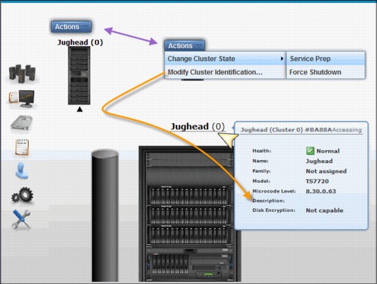
Figure 9-15 Cluster Summary panel
In the Cluster Summary panel, you can access the following options using the Actions drop-down menu:
•Modify Cluster Information
•Change Cluster State → Force Shut Down
•Change Cluster State → Service Prep
You also can display the Cluster Information by hovering the mouse over the Cluster name, as shown in Figure 9-15. In the resulting box, the following information is available:
•Cluster Health Status
•Cluster Name
•Family to which this cluster is assigned
•Cluster model
•Licensed Internal Code (LIC) (Microcode) level for this cluster
•Description for this cluster
•Disk encryption status
Cluster Actions menu
Use this menu to change a cluster state or settings. When attached to a library, use this menu to change Copy Export settings. Change Cluster State can be selected to put the cluster into a different state. Multiple options can be shown, depending on the current state of the cluster.
Table 9-7 on page 440 describes options available to change the state of a cluster.
Table 9-7 Options to change cluster state
|
If the current state is
|
You can select
|
Restrictions and notes
|
|
Online
|
Service Prep
|
All following conditions must first be met:
•The cluster is online.
•No other clusters in the grid are in service prep mode.
•At least one other cluster must remain online.
Caution: If only one other cluster remains online, a single point of failure exists when this cluster state becomes service prep mode.
Select Service Prep to confirm this change.
|
|
Force Shutdown
|
Select Force Shutdown to confirm this change.
Important: After a shutdown operation is initiated, it cannot be canceled.
|
|
|
Service Pending
|
Force Service
|
You can select this option if you think that an operation has stalled and is preventing the cluster from entering Service Prep.
Select Force Service to confirm this change.
Note: You can place all but one cluster in a grid into service mode but it is advised that only one cluster be in service mode at a time. If more than one cluster is in service mode, and you cancel service mode on one of them, that cluster will not return to normal operation until service mode is canceled on all clusters in the grid.
|
|
Return to Normal
|
You can select this option to cancel a previous service prep change and return the cluster to the normal online state.
Select Return to Normal to confirm this change.
|
|
|
Force Shutdown
|
Select Force Shutdown to confirm this change.
Important: After a shutdown operation is initiated, it cannot be canceled.
|
|
|
Shutdown (offline)
|
User interface not available
|
After an offline cluster is powered on, it attempts to return to normal. If no other clusters in the grid are available, you can skip hot token reconciliation.
|
|
Online-Pending or Shutdown Pending
|
Menu disabled
|
No options to change state are available when a cluster is in a pending state.
|
Going offline and coming online
Consider the following information for going offline and coming online:
•Pending token merge: A cluster in a grid configuration attempts to merge its token information with all the other clusters in the grid as it goes online. When no other clusters are available for this merge operation, the cluster attempting to go online remains in the “going online”, or blocked, state indefinitely as it waits for the other clusters to become available for the merge operation. If a pending merge operation is preventing the cluster from coming online, you are given the option to skip the merge step. Click Skip Step to skip the merge operation. This button is only available if the cluster is in a blocked state waiting to share pending updates with one or more unavailable clusters.
If you click Skip Step, pending updates against the local cluster may remain undetected until the unavailable clusters become available.
•Ownership takeover: If ownership takeover was set at any of the peers, the possibility exists that old data can surface to the host if the cluster is forced online. Therefore, before attempting to force this cluster online, it is important to know whether any peer clusters have ever enabled ownership takeover mode against this cluster while it was unavailable. In addition, if this cluster is currently in service, automatic ownership takeover from unavailable peers is also likely and must be considered before attempting to force this cluster online. If multiple clusters have been offline and must be forced back online, force them back online in the reverse order that they went down in (for example, the last cluster down is the first cluster up). This assures that the most current cluster is available first to educate the rest of the clusters forced online.
•Autonomic Ownership Takeover Manager (AOTM): If it is installed and configured, it will attempt to determine if all unavailable peer clusters are actually in a failed state. If it determines that the unavailable cluster is not in a failed state, it will block an attempt to force the cluster online. If the unavailable cluster is not actually in a failed state, the forced online cluster can be taking ownership of volumes that it must not take ownership of. If AOTM discovers that all unavailable peers have failed and network issues are not to blame, this cluster will then be forced into an online state. After it is online, AOTM can further allow ownership takeover against the unavailable clusters if the AOTM option is enabled. Additionally, manual ownership takeover can be enabled, if necessary.
•Shutdown restrictions: You can only shut down the cluster into which you are logged. To shut down another cluster, you must log out of the current cluster and log in to the cluster that you want to shut down.
Before you shut down the TS7700 Virtualization Engine, you must decide whether your circumstances provide adequate time to perform a clean shutdown. A clean shutdown is not required, but is suggested for a TS7700 grid configuration. A clean shutdown requires you to first place the cluster in service mode to ensure that no jobs are being processed during a shutdown operation. If you cannot place the cluster in service mode, you can force a shutdown of the cluster.
|
Tip: A forced shutdown can result in lost access to data and job failure.
|
A cluster shutdown operation initiated from the TS7700 Virtualization Engine MI also shuts down the cache. The cache must be restarted before any attempt is made to restart the TS7700 Virtualization Engine.
Service mode window
Use the window shown in Figure 9-16 on page 442 to put a TS7700 Virtualization Engine Cluster into service mode.

Figure 9-16 TS7700 MI for service preparation
In a TS7700 Virtualization Engine Grid, service prep can occur on only one cluster at any one time. If service prep is attempted on a second cluster at the same time, the attempt fails. After service prep has completed for one cluster and that cluster is in service mode, another cluster can be placed in service prep. A cluster in service prep automatically cancels service prep if its peer in the grid experiences an unexpected outage while the service prep process is still active.
|
Consideration: Although you can place all clusters except one in service mode, the best approach is if only one cluster is in service mode at a time. If more than one cluster is in service mode, and you cancel service mode on one of them, that cluster does not return to normal operation until service mode is canceled on all the clusters.
|
For a TS7720 Virtualization Engine cluster in a grid, you can click Lower Threshold to lower the required threshold at which logical volumes are removed from cache. When the threshold is lowered, additional logical volumes already copied to another cluster are removed, creating additional cache space for host operations. This step is necessary to ensure that logical volume copies can be made and validated before a service mode event. The default removal threshold is equal to 95% of the cache Used Size minus 2 TB (see the Used Size field in the Tape Volume Cache window). You can lower the threshold to any value between 4 TB and the remainder of the Used Size minus 2 TB. More technical details regarding mixed grid and cache thresholds is in 5.4.7, “TS7720 cache thresholds and removal policies” on page 274.
|
Note: If the grid contains both TS7720 and TS7740 clusters, you can lower your removal threshold to prevent a TS7720 cluster from running out of cache when the TS7740 clusters are in service. To lower the removal threshold, click TS7720 Lower Removal Threshold when a TS7720 cluster is in the online state.
|
Figure 9-17 shows the TS7720 Temporary Removal Threshold panel in the TS7700 MI for a mixed grid.

Figure 9-17 TS7720 Temporary Removal Threshold panel
The following items are available when viewing the current operational mode of a cluster:
•Cluster State: Can be any of the following states:
– Normal: The cluster is in a normal operation state. Service prep can be initiated on this cluster.
– Service Prep: The cluster is preparing to go into service mode. The cluster is completing operations (that is, copies owed to other clusters, ownership transfers, and lengthy tasks, such as inserts and token reconciliation) that require all clusters to be synchronized.
– Service: The cluster is in service mode. The cluster is normally taken offline in this mode for service actions or to activate new code levels.
Depending the mode that the cluster is in, a different action is presented by the button below the Cluster State display. You can use this button to place the TS7700 Virtualization Engine into service mode or back into normal mode:
•Prepare for Service Mode: This option puts the cluster into service prep mode and allows the cluster to finish all current operations. If allowed to finish service prep, the cluster enters service mode. This option is only available when the cluster is in normal mode. To cancel service prep mode, click Return to Normal Mode.
•Return to Normal Mode: Returns the cluster to normal mode. This option is available if the cluster is in service prep or service mode. A cluster in service prep mode or service mode returns to normal mode if Return to Normal Mode is selected.
You are prompted to confirm your decision to change the Cluster State. Click Service Prep or Normal Mode to change to new Cluster State, or Cancel to abandon the change operation.
Cluster Shutdown window
Use the window shown in Figure 9-18 on page 445 to remotely shut down a TS7700 Virtualization Engine Cluster for a planned power outage or in an emergency.

Figure 9-18 MI Cluster shutdown window
This window is visible from the TS7700 Virtualization Engine MI whether the TS7700 Virtualization Engine is online or in service. If the cluster is offline, MI will be not available, and the error HYDME0504E The cluster you selected is unavailable will be presented.
You can shut down only the cluster to which you are logged in. To shut down another cluster, you must log out of the current cluster and log in to the cluster you want to shut down. Before you shut down the TS7700 Virtualization Engine Cluster, you must decide whether your circumstances provide adequate time to perform a clean shutdown. A clean shutdown is not required, but is good practice to do for a TS7700 Virtualization Engine Grid configuration. A clean shutdown requires you to first place the cluster in service mode to ensure that no jobs are being processed during a shutdown operation. If you cannot place the cluster in service mode, you can use this window to force a shutdown of the cluster.
|
Important: A forced shutdown can result in lost access to data and job failure.
|
A cluster shutdown operation initiated from the TS7700 Virtualization Engine MI also shuts down the cache. The cache must be restarted before any attempt is made to restart the TS7700 Virtualization Engine.
If you select Shutdown from the action menu for a cluster that is still online, as shown at the top of Figure 9-18 on page 445, a message alerts you to first put the cluster in service mode before shutting down. We show an example of the message in Figure 9-19.

Figure 9-19 Warning message and Cluster Status
In Figure 9-19, the Online State and Service State fields in the message show the operational status of the TS7700 Virtualization Engine and appear above the button used to force its shutdown. On the lower-right corner of the picture, we show the cluster status reported by the message. You have the following options:
•Cluster State. The following values are possible:
– Normal: The cluster is in an online, operational state and is part of a TS7700 Virtualization Engine Grid.
– Service: The cluster is in service mode or is a stand-alone machine.
– Offline: The cluster is offline. It might be shutting down in preparation for service mode.
•Shutdown: This button initiates a shutdown operation:
|
Important: After a shutdown operation is initiated, it cannot be canceled.
|
– Clicking Shutdown in Normal mode: If you click Shutdown while in normal mode, you receive a warning message recommending that you place the cluster in service mode before preceding as shown in Figure 9-19. To place the cluster in service mode, select Modify Service Mode. To continue with the force shutdown operation, provide your password and click Force Shutdown. To abandon the shutdown operation, click Cancel.
– Clicking Shutdown in Service mode: If you select Shutdown while in service mode, you will be asked to confirm your decision. Click Shutdown to continue, or click Cancel to abandon the shutdown operation.
When a shutdown operation is in progress, the Shutdown button is disabled and the status of the operation is displayed in an information message. The following list shows the shutdown sequence:
1. Going offline
2. Shutting down
3. Powering off
4. Shutdown completes
Verify that power to the TS7700 Virtualization Engine and to the cache is shut down before attempting to restart the system.
A cluster shutdown operation initiated from the TS7700 Virtualization Engine MI also shuts down the cache. The cache must be restarted first and allowed to power up to an operational state before any attempt is made to restart the TS7700 Virtualization Engine.
Cluster Identification Properties window
Use the window shown in Figure 9-20 to view and alter cluster identification properties for the TS7700 Virtualization Engine. This can be used to distinguish this distributed library.

Figure 9-20 MI Cluster Identification properties window
The following information related to cluster identification is displayed. To change the cluster identification properties, edit the available fields and click Modify. The following fields are available:
•Cluster nickname: The cluster nickname must be one to eight characters in length and composed of alphanumeric characters. Blank spaces and the characters @, ., -, and + are also allowed. Blank spaces cannot be used in the first or last character position.
•Cluster description: A short description of the cluster. You can use up to 63 characters.
Cluster health and detail
The health of the system is checked and updated automatically from time to time by the TS7700 Virtualization Engine. The information status reflected on this page is not in real time; it shows the status of the last check-out. In order to repopulate the summary panel with updated health status, you can click the Refresh icon. This operation takes some minutes to complete. If this cluster is operating in Write Protect Mode, a lock icon will show in the middle right part of the cluster image.
See Figure 9-21 for reference. In the cluster front view, you see a general description about the cluster, such as model, name, family, microcode level, cluster description, and cache encryption capabilities right in the cluster badge (top of the box picture).
Hovering the mouse cursor over the locations within the picture of the frame shows you the health status of different components, such as the network gear (at the top), Tape Volume Cache (TVC) controller and expansion enclosures (bottom and halfway up), and the engine server along with the internal 3957-Vxx disks (the middle). The summary of cluster health shows at the lower-right status bar, and also at the badge health status (over the frame).

Figure 9-21 Front view of Cluster Summary with health details
In Figure 9-22 on page 449, we show the back view of the cluster summary panel and health details.
The components depicted in the back view are the Ethernet ports and host Fibre Channel connection (FICON) adapters for this cluster. Under the Ethernet tab, you can see the ports dedicated to the internal network (the TSSC network) and those dedicated to the external (client) network. You can see the assigned IP addresses, if IPv4 or IPv6, that are being used, and the health of the ports are shown for those ports. In the grid Ethernet ports, information regarding links to the other clusters, data rates, and cyclic redundancy check (CRC) errors are displayed for each port in addition to the assigned IP address and Media Access Control (MAC) address.
The host FICON adapter information is displayed under the Fibre tab for a selected cluster, as shown in Figure 9-22. The available information includes the adapter position and general health for each port.

Figure 9-22 Back view of the cluster summary with health details
To display the different area health details, hover the mouse over the component in the picture. Table 9-8 defines fields and values displayed in the Cluster Summary panel.
Table 9-8 Fields and values of the cluster summary panel
|
Detail
|
Definition
|
|||
|
Cluster identifier
|
The cluster name followed by the cluster number and distributed library sequence number.
|
|||
|
Accessing Cluster
|
Whether the cluster displayed is the one used to log in to the grid. If these words are absent in the details window, a different cluster in the grid was used when logging in.
|
|||
|
Health State
|
The health of the cluster as a whole. The following values are possible:
•Normal
•Degraded
•Failed
•Service
•Service Prep
•Unknown
|
|||
|
Event
|
Whether an outstanding event exists on the cluster.
If a value other than Normal occurs in this field, you can click the icon to launch the Events panel and review details of the event.
|
|||
|
Family
|
The name of the family to which the cluster is assigned.
|
|||
|
Model
|
The cluster model number. The following values are possible:
•TS7720
•TS7740
|
|||
|
Microcode
|
The microcode level at which the cluster operates.
|
|||
|
Name
|
The cluster name.
|
|||
|
Description
|
The cluster description.
|
|||
|
Disk Encryption
|
Whether disk encryption is in effect and if so, whether a local or external key manager is in use.
|
|||
Cache expansion frame
The expansion frame view displays details and health for a cache expansion frame attached to the TS7720 Cluster. To open the expansion frame view, click the small image corresponding to a specific expansion frame, beneath the Actions button.
|
Tip: The expansion frame icon will only be displayed if the accessed cluster has an expansion frame.
|
Check Figure 9-23 for a visual reference.

Figure 9-23 Cache expansion frame details and health
Physical library and tape drive health
The Physical Library icon, visible in a TS7740 Cluster Summary panel, allows you to check the health of the tape library and tape drives by clicking it. See Figure 9-24 on page 451.
|
Restriction: If the cluster is not a TS7740, the Tape Library icon does not display on the TS7700 Virtualization Engine MI.
|
Also, clicking on the TS3500 Tape Library Expanded picture will launch the TS3500 Library Specialist web interface.

Figure 9-24 TS7700 Virtualization Engine MI physical tape drives
The library details and health are displayed as explained in Table 9-9.
Table 9-9 Library health details
|
Detail
|
Definition
|
|||
|
Physical library type - virtual library name
|
The type of physical library (type is always TS3500) accompanied by the name of the virtual library established on the physical library.
|
|||
|
Tape Library Health
Fibre Switch Health
Tape Drive Health
|
The health states of the library and its main components. The following values are possible:
•Normal
•Degraded
•Failed
•Unknown
|
|||
|
State
|
Whether the library is online or offline to the TS7700 Virtualization Engine.
|
|||
|
Operational Mode
|
The library operational mode. The following values are possible:
•Auto
•Paused
|
|||
|
Frame Door
|
Whether a frame door is open or closed.
|
|||
|
Virtual I/O Slots
|
Status of the I/O station used to move cartridges into and out of the library. The following values are possible:
•Occupied
•Full
•Empty
|
|||
|
Physical Cartridges
|
The number of physical cartridges assigned to the identified virtual library.
|
|||
|
Tape Drives
|
The number of physical tape drives available, as a fraction of the total. Click this detail to open the Physical Tape Drives panel.
|
|||
From the TS3500 Tape Library Expanded page, you can navigate to the Physical Tape Drives panel. Just click the Tape Drives item in the health report, as shown in Figure 9-25.
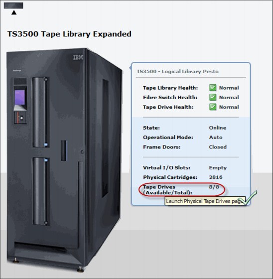
Figure 9-25 Navigating to the Physical Tape Drives panel
The Physical Tape Drives panel looks similar to the example in Figure 9-26 on page 453.
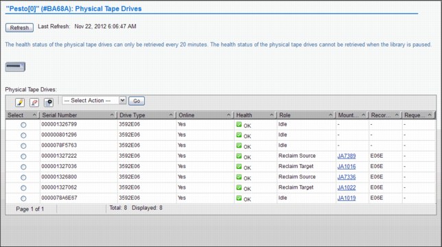
Figure 9-26 Physical Tape Drives panel
On the Physical Tape Drives panel, you see all the specific details about a physical tape drive, such as its serial number, drive type, whether the drive has a cartridge mount on it, what is it mounted for, among others. To see the same information, such as drive encryption, tape library location, and so on, about the other tape drives, select a specific drive and choose Details in the Select Action pop-up panel. The detailed drive information panel is shown in Figure 9-27.

Figure 9-27 Physical Tape Drive Details and navigation
9.2.4 The Monitor icon
The collection of pages under the Monitor icon in the MI allow you to monitor events in the TS7700 Virtualization Engine.
Events encompass every significant occurrence within the TS7700 Virtualization Grid or Cluster, such as a malfunctioning alert, an operator intervention, a parameter change, a warning message, or some user-initiated action.
|
Operator Intervention: Messages are now displayed under Events with R3.0 MI.
|
Figure 9-28 shows the Monitor icon in a grid and in a stand-alone cluster.

Figure 9-28 Monitor icon in a grid or stand-alone configuration
|
Tip: Notice in Figure 9-28 that the Systems icon only shows up in a grid configuration, and the Cluster Summary item only shows up under Monitor in a stand-alone configuration.
|
Events
Use this window, shown in Figure 9-29, to view all meaningful events that occurred within the grid or a stand-alone TS7700 Virtualization Engine Cluster.
You have the choice to send future events to the host operational system, by enabling host notification. Although events are grid-wide, enabling or disabling host notification will only affect the accessing cluster, which is the cluster that you are currently in, if this is a grid configuration. Also, task events are not sent to the host.
Information is displayed on the Events table for 30 days after the operation stops or the event becomes inactive.

Figure 9-29 TS7700 Management Interface Events window
Figure 9-30 on page 456 shows the alerts, tasks, and event values and associated severity icons in the Events panel in the MI.
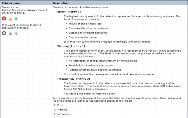
Figure 9-30 Alerts, tasks, and event values and associated severity icons
Table 9-10 describes the column names and descriptions of the fields, as shown in the Event panel (see Figure 9-29 on page 455).
Table 9-10 Field name and description for the Events panel
|
Column name
|
Description
|
|||
|
Date & Time
|
Date and time the event occurred.
|
|||
|
Source
|
Cluster where the event occurred.
|
|||
|
Location
|
Specific location on the cluster where the event occurred.
|
|||
|
Description
|
Description of the event.
|
|||
|
ID
|
The unique number that identifies the instance of the event. This number consists of these values:
•A locally generated ID, for example: 923
•The type of event: E (event) or T (task)
An event ID based on these examples appears as 923E.
|
|||
|
Status
|
The status of an alert or task.
If the event is an alert, this value is a fix procedure to be performed or the status of a call home operation.
If the event is a task, this value is its progress or one of these final status categories:
•Canceled
•Canceling
•Completed
•Completed, with information
•Completed, with warning
•Failed
|
|||
|
System Clearable
|
Whether the event can be cleared automatically by the system. The following values are possible:
Yes. The event will be cleared automatically by the system when the condition causing the event has been resolved.
No. The event requires user intervention to clear. You must clear or deactivate the event manually after resolving the condition causing the event.
|
|||
Table 9-11 lists actions that can be performed on the Events table.
Table 9-11 Actions that can be performed on the Events table
|
To perform this task
|
Action
|
|||
|
Deactivate or clear one or more alerts
|
1. Select at least one but no more than 10 events.
2. Click Mark Inactive.
If a selected event is normally cleared by the system, you must confirm your selection. Other selected events are cleared immediately.
Note: You can clear a running task but if the task later fails, it is displayed again as an active event.
|
|||
|
Enable or disable host notification for alerts
|
Select Actions → [Enable/Disable] Host Notification. This change affects only the accessing cluster.
Note: Tasks are not sent to the host.
|
|||
|
View a recommended fix procedure for an alert
|
Select Actions → View Fix Procedure.
Note: A fix procedure can be shown for only one alert at a time. No fix procedures are shown for tasks.
|
|||
|
Download a comma-separated value (CSV) file of the events list
|
Select Actions → Download all Events.
|
|||
|
View additional details for a selected event
|
1. Select an event.
2. Select Actions → Properties.
|
|||
|
Hide or show columns on the table
|
1. Right-click the table header.
2. Click the check box next to a column heading to hide or show that column in the table. Column headings that are checked display on the table.
|
|||
|
Filter the table data
|
Follow these steps to filter by using a string of text:
1. Click in the Filter field.
2. Enter a search string.
3. Press Enter.
To filter by column heading:
1. Click the down arrow next to the Filter field.
2. Select the column heading to filter by.
3. Refine the selection.
|
|||
|
Reset the table to its default view
|
1. Right-click on the table header.
2. Click Reset Table Preferences.
|
|||
Performance
This section introduces the performance and statistic windows available in the TS7700 Virtualization Engine MI. Chapter 10, “Performance and monitoring” on page 653 presents and describes the graphical information available for monitoring your TS7700 Virtualization Engine and how it can be used to maximize subsystem resources.
See “IBM Virtualization Engine TS7700 Series Best Practices - Understanding, Monitoring, and Tuning the TS7700 Performance”, WP101465, which is available in the IBM Techdocs Library at this website:
The WP101465 paper is an in-depth study of the inner workings of the TS7700 and the factors that can affect the overall performance of a stand-alone cluster or a TS7700 grid. Also, it explains throttling mechanisms and available tuning knobs that can be adjusted in the subsystem to achieve peak performance.
All graphical views, except the Historical Summary, are from the last 15 minutes. The Historical Summary presents a customized graphical view of the different aspects of the cluster operation, in a 24-hour time frame. This 24-hour window can be “slid” back up to 90 days, which covers three months of operations.
Figure 9-31 shows the Historical Summary of the Performance MI operation, showing the selection, available items, and the resulting panel, from left to right.
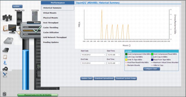
Figure 9-31 Performance panel operation
We show in the Figure 9-32 on page 459 another Historical Summary sample, from the same cluster but selecting a different 24-hour period. The Configure Chart pop-up window is shown at the lower-left corner of the picture. Notice “Update Chart, Download Spreadsheet” and “Download System Usage” at the bottom of the picture. You can request the raw data for the System Usage (CPU usage percentage, in 15-minute intervals, of the selected interval) by using “Download System Usage”. “Download Spreadsheet” will show you the raw data of the customized view of the Historical Summary graphic. “Update Chart” is used to repopulate the chart after changing the period or customizing the chart buildup. Downloadable data is also limited to a 24-hour period from the start date and time defined in the panel.
The Performance panels are meant to be used as the TS7700 Virtualization Engine dashboard, where the support personnel can analyze the subsystem in real time. See Chapter 10, “Performance and monitoring” on page 653 for guidance about statistical data collection and a description of the available tools for a more comprehensive performance evaluation.
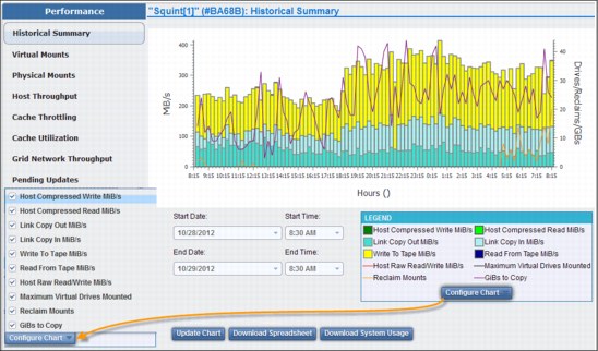
Figure 9-32 Historical Summary sample
You can select the following items under Performance:
Historical summary Use this page to view performance data for a specific TS7700 Virtualization Engine Cluster.
Virtual mounts Use this page to view virtual mount statistics for the IBM Virtualization Engine TS7700 Grid.
Physical mounts Use this page to view physical mount statistics for the IBM Virtualization Engine TS7700 Grid.
Host throughput Use this page to view host throughput statistics for the IBM Virtualization Engine TS7700 Grid.
Cache throttling Use this page to view statistics for throttling applied to copy operations or host write operations on the IBM Virtualization Engine TS7700 Grid.
Cache utilization Use this page to view cache utilization statistics for the IBM Virtualization Engine TS7700 Cluster.
Grid network throughput
Use this page to view network throughput statistics for the IBM Virtualization Engine TS7700 Grid.
Use this page to view network throughput statistics for the IBM Virtualization Engine TS7700 Grid.
Pending updates Use this page to view the pending updates for the IBM Virtualization Engine TS7700 Grid. The existence of pending updates indicates that updates occurred while a cluster was Offline, in service prep mode, or in service mode. Before any existing pending updates can take effect, all clusters must be online.
Tasks panel
This page is used to monitor the status of tasks submitted to the TS7700 Virtualization Engine. You will find information for an entire grid if the accessing cluster is part of a grid, or only for this individual cluster if this is a stand-alone configuration. You can format the table by using filters, or you can reset the table format to its default by using reset table preferences. Information is available in the task table for 30 days after the operation stops or the event or action becomes inactive.
Tasks are listed by starting date and time. Tasks that are still running are shown on the top of the table, while the completed tasks are listed below. Figure 9-33 shows an example of the Tasks panel.
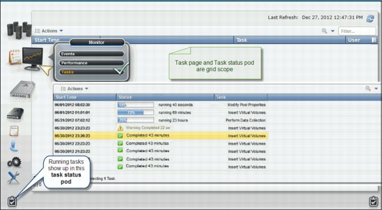
Figure 9-33 Tasks panel
9.2.5 The Virtual icon
TS7700 Virtualization Engine MI pages collected under the Virtual icon can help you view or change settings related to virtual volumes and their queues, virtual drives, and scratch (Fast Ready) categories.
Figure 9-34 on page 461 shows the Virtual icon and the selection of items under it.

Figure 9-34 The Virtual icon and options
The available items under the Virtual icon are described.
Incoming copy queue
Use this page to view the virtual volume incoming copy queue for an IBM Virtualization Engine TS7700 cluster. The incoming copy queue represents the amount of data waiting to be copied to a cluster. Data written to a cluster in one location can be copied to other clusters in a grid to achieve uninterrupted data access. You can specify on which clusters (if any) copies reside, and how quickly copy operations occur. Each cluster maintains its own list of copies to acquire, and then satisfies that list by requesting copies from other clusters in the grid according to queue priority. Table 9-12 on page 462 shows the values displayed in the copy queue table.
Table 9-12 Values in the copy queue table
|
Column type
|
Description
|
|||
|
Copy Type
|
The type of copy that resides in the queue. The following values are possible:
•Immediate: Volumes can reside in this queue if they are assigned to a Management Class that uses the Rewind Unload (RUN) copy mode.
•Synchronous-deferred: Volumes can reside in this queue if they are assigned to a Management Class that uses the Synchronous mode copy and some event (such as the secondary cluster going offline) prevented the secondary copy from occurring.
•Immediate-deferred: Volumes can reside in this queue if they are assigned to a Management Class that uses the RUN copy mode and some event (such as the secondary cluster going offline) prevented the immediate copy from occurring.
•Deferred: Volumes can reside in this queue if they are assigned to a Management Class that uses the Deferred copy mode.
•Copy-refresh: Volumes can reside in this queue if the Management Class assigned to the volumes has changed and a LIB REQ command was issued from the host to initiate a copy.
•Family-deferred: Volumes can reside in this queue if they are assigned to a Management Class that uses RUN or Deferred copy mode and cluster families are being used.
|
|||
|
Last TVC Cluster
|
The name of the cluster where the copy last resided in the TVC. Although this might not be the cluster from which the copy is received, the majority of copies are typically obtained from the TVC cluster.
Note: This column is only shown when “View by Last TVC” is selected.
|
|||
|
Size
|
Total size of the queue, displayed in GiB.
Note: See 1.5, “Data storage values” on page 13 for additional information concerning the use of binary prefixes.
When Copy Type is selected, this value is per copy type. When “View by Last TVC” is selected, this value is per cluster.
|
|||
|
Quantity
|
The total number of copies in queue for each type.
|
|||
Figure 9-35 on page 463 shows the incoming copy queue page and other places in the Grid Summary and Cluster Summary that inform the user about the current copy queue for a specific cluster.

Figure 9-35 Incoming copy queue
Using the upper-left option, you can choose between “View by Type” or “View by Last TVC Cluster”. The Actions pull-down menu allows you to download the Incoming Queued Volumes list.
Recall queue
The Recall Queue panel of the MI displays the list of virtual volumes in the recall queue. You can use this panel to promote a virtual volume or filter the contents of the table. This page is visible but disabled on the TS7700 Virtualization Engine MI if the grid possesses a physical library, but the selected cluster does not. The following message is displayed:
The cluster is not attached to a physical tape library.
|
Tip: This page is not visible on the TS7700 Virtualization Engine MI if the grid does not possess a physical library.
|
A recall of a virtual volume retrieves the virtual volume from a physical cartridge and places it in the cache. A queue is used to process these requests. Virtual volumes in the queue are classified into three groups:
•In Progress
•Scheduled
•Unscheduled
Figure 9-36 on page 464 shows an example of the Recall queue panel.

Figure 9-36 Recall queue panel
Table 9-13 shows the names and the descriptions of the values that might be seen on the Recall panel.
Table 9-13 Recall panel values
|
Column name
|
Description
|
|||
|
Position
|
The position of the virtual volume in the recall queue. The following values are possible:
•In Progress: A recall is in progress for the volume.
•Scheduled: The volume is scheduled to be recalled. If optimization is enabled, the TS7700 Virtualization Engine will schedule recalls to be processed from the same physical cartridge.
•Position: A number that represents the volume’s current position in the list of volumes that have not yet been scheduled.
These unscheduled volumes can be promoted using the Actions menu.
|
|||
|
Virtual Volume
|
The virtual volume to be recalled.
|
|||
|
Physical Cartridges
|
The serial number of the physical cartridge on which the virtual volume resides. This column can be hidden.
|
|||
|
Time in Queue
|
Length of time the virtual volume has been in the queue, displayed in hours, minutes, and seconds as HH:MM:SS. This column can be hidden.
|
|||
In addition to changing the recall table’s appearance by hiding and showing some columns, the user can filter the data shown in the table by a string of text or by the column heading. Possible selections are by Virtual Volume, Position, Physical Cartridge, or by Time in Queue. To reset the table to its original appearance, click Reset Table Preferences.
Another interaction now available in the Recall panel is that the user can promote an unassigned volume recall to the first position in the unscheduled portion of the recall queue. This is available by checking an unassigned volume in the table, and from the pull-down menu under Actions, select Promote Volume.
Virtual tape drives
The Virtual Tape Drives page of the MI presents the status of all virtual tape drives in a cluster. You can use this page to check the status of a virtual mount, mount or unmount a volume, or assign host device numbers. Figure 9-37 shows the Virtual tape drives panel and the Actions pull-down menu.

Figure 9-37 Virtual Tape Drives panel
See Table 9-14 on page 466 to identify the properties of virtual tape drives.
Table 9-14 Properties displayed for virtual tape drives
|
Column name
|
Description
|
|||
|
Address
|
The virtual drive address takes the format vtdXXXX, where X is a hexadecimal number.
|
|||
|
Host Device Number
|
The device identifier as defined in the attached host. The value in this field does not affect drive operations, but if the host device number is set, it is easier to compare the virtual tape drives to their associated host devices.
Follow these steps to add host device numbers:
1. Select one or more virtual tape drives.
2. Select Assign Host Device Numbers from the Actions menu.
3. Enter the host device address that you want assigned to the first virtual tape drive. Host device numbers are added to subsequent virtual tape drives incrementally.
|
|||
|
Mounted Volume
|
The volume serial number (VOLSER) of the mounted virtual volume.
|
|||
|
Previously Mounted Volume
|
The VOLSER of the virtual volume mounted on the drive prior to this one.
|
|||
|
Status
|
The role that the drive is performing. The following values are possible:
Idle: The drive is not in use.
Read: The drive is reading a virtual volume.
Write: The drive is writing a virtual volume.
This column is blank if no volume is mounted.
|
|||
|
Time on Drive
|
The elapsed time that the virtual volume has been mounted on the virtual tape drive.
This column is blank if no volume is mounted.
|
|||
|
Cache Mount Cluster
|
The TVC cluster performing the mount operation. If a synchronous mount exists, this field displays two clusters.
This column is blank if no volume is mounted.
|
|||
|
Online
|
Whether the mounting virtual tape drive is online.
|
|||
|
Bytes Read
|
Amount of data read from the mounted virtual volume. This value is shown as Raw KiB (Compressed KiB).
|
|||
|
Bytes Written
|
Amount of data that was written to the mounted virtual volume. This value is shown as Raw KiB (Compressed KiB).
|
|||
|
Virtual Block Position
|
The position of the drive on the tape surface in a block number, as calculated from the beginning of the tape. This value is displayed in hexadecimal form. When a volume is not mounted, this value is 0x0.
|
|||
|
Stand-alone Mount
|
Whether the virtual drive is a stand-alone mount, which means that the mount request is initiated by the cluster and not the host.
Follow these steps to mount a virtual volume:
1. Select a volume.
2. Select Stand-alone Mount from the Actions menu.
Note: You can only mount virtual volumes not already mounted, on a drive that is online.
Follow these steps to unmount a virtual volume:
1. Select a mounted volume.
2. Select Unmount from the Actions menu.
Note: You can unmount only those virtual volumes that are mounted and have a status of Idle.
|
|||
Virtual volumes
The topics in this section present information related to monitoring and manipulating virtual volumes in the IBM Virtualization Engine TS7700.
Virtual volume details
Figure 9-38 on page 468 and Figure 9-41 on page 470 show a sample of the Virtual Volume Details page. The entire page can be subdivided in three parts:
1. Virtual volume summary
2. Virtual volume details
3. Cluster-specific virtual volume properties
In Figure 9-38 on page 468, you can see the graphical summary for virtual volume Z22208. The virtual volume is in primary cache at Cluster 1, which is the owner of volume Z22208. The cluster, which owns the volume, is indicated by the blue halo around it. Virtual volume Z22208 is in the Deferred incoming copy queue at Cluster 0 and Cluster 2.
There is a tutorial available about virtual volume display and how to interpret the panels accessible directly from the MI panel. To watch it, click in the link View Tutorial on the Virtual Volume Detail page.
The first part of the Virtual Volume Details page in the MI shows a graphical summary of the status of the virtual volume being displayed.

Figure 9-38 Virtual Volume Details (Part 1 of 3)
This graphical summary brings details of the present status of the virtual volume within the grid, plus the current operations taking place throughout the grid regarding that volume. Looking at the graphical summary, it is possible to understand the dynamics of a logical mount, whether the volume is in cache at the mounting cluster, or whether it is being recalled from tape in a remote location. Check Figure 9-39 on page 469 for a visual guide of the graphical area.
|
Note: If the cluster does not possess a physical library, physical resources are not shown in the virtual volume summary, virtual volume details table, or the cluster-specific virtual volume properties table.
|

Figure 9-39 Details of the graphical summary area
Additional legends used in the graphical representation of virtual volume details in the TS7700 Virtualization Engine MI are shown in Figure 9-40.
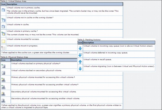
Figure 9-40 Legend list for the graphical representation of the virtual volume details
Figure 9-41 shows the second part of the Virtual volume details panel of the TS7700 Virtualization Engine MI, complementing the information about volume Z22208. Details, such as the media type, compressed data size, current owner, whether the volume is currently mounted and where, and so on, are presented. It displays other properties for this volume, such as copy retention, copy policy, whether an automatic removal was attempted or not, and when if so.

Figure 9-41 Virtual volume details (Part 2 of 3)
Virtual volume details
The virtual volume details and status are displayed in the Virtual volume details table:
Volser The VOLSER of the virtual volume. This value is a six-character number that uniquely represents the virtual volume in the virtual library.
Media Type The media type of the virtual volume. The possible values are Cartridge System Tape (400 MiB) or Enhanced Capacity Cartridge System Tape (800 MiB).
Compressed Data Size
The compressed file size of the virtual volume in cache expressed in mebibytes (MiB).
The compressed file size of the virtual volume in cache expressed in mebibytes (MiB).
Maximum Volume Capacity
The maximum size of the virtual volume is expressed in mebibytes (MiB). This capacity is set initially upon insert and based on the media type of a virtual volume. If an override is configured for the Data Class’ maximum size, the override is only applied when a volume is mounted and a load-point write (scratch (Fast Ready) mount) occurs. During the close operation for the volume, the new override value is bound to the volume and cannot change until the volume is again reused. Therefore, any further changes to a Data Class override are not inherited by a volume until it is written again during a scratch (Fast Ready) mount and then closed.
The maximum size of the virtual volume is expressed in mebibytes (MiB). This capacity is set initially upon insert and based on the media type of a virtual volume. If an override is configured for the Data Class’ maximum size, the override is only applied when a volume is mounted and a load-point write (scratch (Fast Ready) mount) occurs. During the close operation for the volume, the new override value is bound to the volume and cannot change until the volume is again reused. Therefore, any further changes to a Data Class override are not inherited by a volume until it is written again during a scratch (Fast Ready) mount and then closed.
Current Owner The name of the cluster that currently owns the latest version of the virtual volume.
Currently Mounted Indicates whether the virtual volume is currently mounted in a virtual drive.
vNode The name of the vNode on which the virtual volume is mounted.
Virtual Drive The ID of the virtual drive on which the virtual volume is mounted.
Cache Copy Used for Mount
The cluster name of the cache that was chosen for I/O operations for mount based on Consistency policy, volume validity, residency, performance, and cluster mode.
The cluster name of the cache that was chosen for I/O operations for mount based on Consistency policy, volume validity, residency, performance, and cluster mode.
Cache Management Preference Group
The preference level for the Storage Group; it determines how soon volumes are removed from cache following their copy to tape. This information is only displayed if a physical library exists in the grid. The following values are possible:
The preference level for the Storage Group; it determines how soon volumes are removed from cache following their copy to tape. This information is only displayed if a physical library exists in the grid. The following values are possible:
0 Volumes in this group have preference to be removed from cache over other volumes.
1 Volumes in this group have preference to be retained in cache over other volumes. A “least recently used” (LRU) algorithm is used to select volumes for removal from cache if there are no volumes to remove in preference group 0.
Unknown The preference group cannot be determined.
Mount State The current mount state of the virtual volume. The following values are possible:
Mounted The volume is mounted.
Mount Pending A mount request has been received and is in progress.
Recall Queued/Requested
A mount request has been received and a recall request has been queued.
A mount request has been received and a recall request has been queued.
Recalling A mount request has been received and the virtual volume is currently being staged into the TVC from physical tape.
Last Accessed by a Host
The date and time that the virtual volume was last accessed by a host. Time recorded reflects the time zone in which the user’s browser is located.
The date and time that the virtual volume was last accessed by a host. Time recorded reflects the time zone in which the user’s browser is located.
Last Modified The date and time the virtual volume was last modified by a host. Time recorded reflects the time zone in which the user’s browser is located.
Category The number of the scratch (Fast Ready) category to which the virtual volume belongs. A scratch (Fast Ready) category groups virtual volumes for quick, non-specific use.
Storage Group The name of the Storage Group that defines the primary pool for the premigration of the virtual volume.
Management Class The name of the Management Class applied to the volume. This policy defines the copy process for volume redundancy.
Storage Class The name of the Storage Class applied to the volume. This policy classifies virtual volumes to automate storage management.
Data Class The name of the Data Class applied to the volume. This policy classifies virtual volumes to automate storage management.
Volume Data State The state of the data on the virtual volume. The following values are possible:
New The virtual volume is in the insert category or a private (non-Fast Ready) category and data has never been written to it.
Active The virtual volume is currently located within a private category and contains data.
Scratched The virtual volume is currently located within a scratch (Fast Ready) category and its data is not scheduled to be automatically deleted.
Pending Deletion The volume is currently located within a scratch (Fast Ready) category and its contents are a candidate for automatic deletion when the earliest deletion time has passed. Automatic deletion then occurs sometime later. Note that the volume can be accessed for mount or category change before the automatic deletion and therefore the deletion can be incomplete.
Pending Deletion with Hold
The volume is currently located within a scratch (Fast Ready) category configured with hold and the earliest deletion time has not yet passed. The volume is not accessible by any host operation until the volume has left the hold state. Once the earliest deletion time has passed, the volume then becomes a candidate for deletion and moves to the Pending Deletion state. While in this state, the volume is accessible by all legal host operations.
The volume is currently located within a scratch (Fast Ready) category configured with hold and the earliest deletion time has not yet passed. The volume is not accessible by any host operation until the volume has left the hold state. Once the earliest deletion time has passed, the volume then becomes a candidate for deletion and moves to the Pending Deletion state. While in this state, the volume is accessible by all legal host operations.
Deleted The volume is either currently within a scratch (Fast Ready) category or has previously been in a scratch (Fast Ready) category where it became a candidate for automatic deletion and was deleted. Any mount operation to this volume is treated as a scratch (Fast Ready) mount since no data is present.
Earliest Deletion On The date and time when the virtual volume is deleted. Time recorded reflects the time zone in which the user’s browser is located. If there is no expiration date set, this value displays as “—”.
Logical WORM Whether the virtual volume is formatted as a Write Once, Read Many (WORM) volume. The possible values are Yes and No.
Cluster-specific Virtual Volume Properties
Figure 9-42 shows the Cluster-specific Virtual Volume Properties table shown in the Virtual volume details page.

Figure 9-42 Cluster-specific virtual volume properties (Part 3 of 3)
The Cluster-specific Virtual Volume Properties table displays information about requesting virtual volumes on each cluster. These are properties that are specific to a cluster. Virtual volume details and the status displayed include the following properties:
Cluster The cluster location of the virtual volume copy. Each cluster location occurs as a separate column header.
In Cache Whether the virtual volume is in cache for this cluster.
Primary Physical Volume
The physical volume that contains the specified virtual volume. Click the VOLSER hyperlink to open the Physical Stacked Volume Details page for this physical volume. A value of None means that no primary physical copy is to be made. This column is only visible if a physical library is present in the grid. If there is at least one physical library in the grid, the value in this column is shown as “—” for those clusters not attached to a physical library.
The physical volume that contains the specified virtual volume. Click the VOLSER hyperlink to open the Physical Stacked Volume Details page for this physical volume. A value of None means that no primary physical copy is to be made. This column is only visible if a physical library is present in the grid. If there is at least one physical library in the grid, the value in this column is shown as “—” for those clusters not attached to a physical library.
Secondary Physical Volume
A secondary physical volume that contains the specified virtual volume. Click the VOLSER hyperlink to open the Physical Stacked Volume Details page for this physical volume. A value of None means that no secondary physical copy is to be made. This column is only visible if a physical library is present in the grid. If there is at least one physical library in the grid, the value in this column is shown as “—” for those clusters not attached to a physical library.
A secondary physical volume that contains the specified virtual volume. Click the VOLSER hyperlink to open the Physical Stacked Volume Details page for this physical volume. A value of None means that no secondary physical copy is to be made. This column is only visible if a physical library is present in the grid. If there is at least one physical library in the grid, the value in this column is shown as “—” for those clusters not attached to a physical library.
Copy Activity Status information about the copy activity of the virtual volume copy. The following values are possible:
Complete A consistent copy exists at this location.
In Progress A copy is required and currently in progress.
Required A copy is required at this location but has not started or completed.
Not Required A copy is not required at this location.
Reconcile Pending updates exist against this location’s volume. The copy activity updates after the pending updates get resolved.
Queue Type The type of queue as reported by the cluster. The following values are possible:
Rewind Unload (RUN)
The copy occurs before the rewind-unload operation completes at the host.
The copy occurs before the rewind-unload operation completes at the host.
Deferred The copy occurs some time after the rewind-unload operation completes at the host.
Sync Deferred The copy was set to be synchronized, according to the synchronized mode copy settings, but the synchronized cluster was unable to be accessed. The copy is in the Deferred state. See “Synchronous mode copy” on page 70 for additional information about Synchronous mode copy settings and considerations.
Immediate Deferred A RUN copy that has been moved to the Deferred state due to copy timeouts or TS7700 grid states.
Copy Mode The copy behavior of the virtual volume copy. The following values are possible:
Rewind Unload (RUN)
The copy occurs before the rewind-unload operation completes at the host.
The copy occurs before the rewind-unload operation completes at the host.
Deferred The copy occurs some time after the rewind-unload operation at the host.
No Copy No copy is made.
Sync The copy occurs upon any synchronization operation. See “Synchronous mode copy” on page 70 for additional information about settings and considerations.
Exist A consistent copy exists at this location although No Copy is intended. A consistent copy existed at this location at the time that the virtual volume was mounted. After the volume is modified, the Copy Mode of this location changes to No Copy.
Deleted The date and time when the virtual volume on the cluster was deleted. Time recorded reflects the time zone in which the user’s browser is located. If the volume has not been deleted, this value displays as “—”.
Removal Residency The residency state of the virtual volume. This field is displayed only if the grid contains a disk-only cluster. The following values are possible:
“—” Removal Residency does not apply to the cluster. This value is displayed if the cluster attaches to a physical tape library.
Removed The virtual volume has been removed from the cluster.
No Removal Attempted
The virtual volume is a candidate for removal, but the removal has not yet occurred.
The virtual volume is a candidate for removal, but the removal has not yet occurred.
Retained An attempt to remove the virtual volume occurred, but the operation failed. The copy on this cluster cannot be removed based on the configured copy policy and the total number of configured clusters. Removal of this copy lowers the total number of consistent copies within the grid to a value below the required threshold. If a removal is expected at this location, verify that the copy policy is configured appropriately and that copies are being replicated to other peer clusters. This copy can be removed only after a sufficient number of replicas exist on other peer clusters.
Deferred An attempt to remove the virtual volume occurred, but the operation failed. This state can result from a cluster outage or any state within the grid that disables or prevents replication. The copy on this cluster cannot be removed based on the configured copy policy and the total number of available clusters capable of replication. Removal of this copy lowers the total number of consistent copies within the grid to a value below the required threshold. This copy can be removed only after a sufficient number of replicas exist on other available peer clusters. A subsequent attempt to remove this volume occurs after no outage exists and replication is allowed to continue.
Pinned The virtual volume is pinned by the virtual volume storage class. The copy on this cluster cannot be removed until it is unpinned. When this value is present, the Removal Time value is Never.
Held The virtual volume is held in cache on the cluster at least until the Removal Time has passed. Once the removal time has passed, the virtual volume copy is a candidate for removal. The Removal Residency value becomes No Removal Attempted if the volume is not accessed before the Removal Time passes. The copy on this cluster is moved to the Resident state if it is not accessed before the Removal Time passes. If the copy on this cluster is accessed after the Removal Time has passed, it is moved back to the Held state.
Removal Time This field is displayed only if the grid contains a disk-only cluster. Values displayed in this field are dependent on values displayed in the Removal Residency fields shown in Table 9-15.
Table 9-15 Removal Time and Removal Residency value
|
Removal Residency state
|
Removal Time indicator
|
|||
|
Removed
|
The date and time the virtual volume was removed from the cluster.
|
|||
|
Held
|
The date and time the virtual volume becomes a candidate for removal.
|
|||
|
Pinned
|
The virtual volume is never removed from the cluster.
|
|||
|
No Removal Attempted, “—”, Retained, or Deferred
|
“—”
The Removal Time field is not applicable.
|
|||
Time recorded reflects the time zone in which the user’s browser is located.
|
Note: If the cluster contains a physical library, Removal Residency does not apply and this field displays a value of “—”.
|
Volume Copy Retention Group
The name of the group that defines the preferred Auto Removal policy applicable to the virtual volume. The Volume Copy Retention Group provides additional options to remove data from a disk-only TS7700 Virtualization Engine as the active data reaches full capacity. Volumes become candidates for removal if an appropriate number of copies exist on peer clusters and the volume copy retention time has elapsed since the volume was last accessed. Volumes in each group are removed in order based on their least recently used access times. The volume copy retention time describes the number of hours a volume remains in cache before becoming a candidate for removal.
The name of the group that defines the preferred Auto Removal policy applicable to the virtual volume. The Volume Copy Retention Group provides additional options to remove data from a disk-only TS7700 Virtualization Engine as the active data reaches full capacity. Volumes become candidates for removal if an appropriate number of copies exist on peer clusters and the volume copy retention time has elapsed since the volume was last accessed. Volumes in each group are removed in order based on their least recently used access times. The volume copy retention time describes the number of hours a volume remains in cache before becoming a candidate for removal.
This field is displayed only if the cluster is a disk-only cluster or part of a hybrid grid (one that combines TS7740 and TS7720 clusters). If the virtual volume is in a scratch (Fast Ready) category and resides on a disk-only cluster, removal settings no longer apply to the volume and the volume is a candidate for removal. In this instance, the value displayed for the Volume Copy Retention Group is accompanied by a warning icon. The following values are possible:
Prefer Remove Removal candidates in this group are removed prior to removal candidates in the Prefer Keep group.
Prefer Keep Removal candidates in this group are removed after removal candidates in the Prefer Remove group.
Pinned Copies of volumes in this group are never removed from the accessing cluster. The volume copy retention time does not apply to volumes in this group. Volumes in this group that are subsequently moved to scratch become priority candidates for removal.
“-” Volume Copy Retention does not apply to a TS7740 cluster. This value (a dash indicating an empty value) is displayed if the cluster attaches to a physical tape library.
|
Important: Care must be taken when assigning volumes to this group to avoid cache overruns.
|
Insert Virtual Volumes
Use this page to insert a range of virtual volumes in the TS7700 Virtualization Engine. Virtual volumes inserted on an individual cluster will be available to all clusters within a grid configuration. The Insert Virtual Volumes panel is shown in Figure 9-43 on page 477.

Figure 9-43 Insert Virtual Volumes panel
The Insert Virtual Volume panel shows the Currently availability across entire grid table. This table shows the total of the already inserted volumes, the maximum number of volumes allowed in the grid, and the available slots (the difference between the maximum allowed and the currently inserted numbers). Clicking “Show/Hide” under the table shows up or hides the information box with the already inserted volume ranges, quantities, media type, and capacity. Figure 9-45 on page 479 shows the inserted ranges box.

Figure 9-44 Show logical volume ranges
Insert a new virtual volume range
Use the following fields to insert a range of new virtual volumes:
Starting volser The first virtual volume to be inserted. The range for inserting virtual volumes begins with this VOLSER number.
Quantity Select this option to insert a set number of virtual volumes beginning with the Starting volser. Enter the quantity of virtual volumes to be inserted in the adjacent text field. You can insert up to 10,000 virtual volumes at one time.
Ending volser Select this option to insert a range of virtual volumes. Enter the ending VOLSER number in the adjacent text field.
Initially owned by The name of the cluster that will own the new virtual volumes. Select a cluster from the drop-down menu.
Media type Media type of the virtual volumes. The following values are possible: Cartridge System Tape (400 MiB) or Enhanced Capacity Cartridge System Tape (800 MiB).
See 1.5, “Data storage values” on page 13 for additional information concerning the use of binary prefixes.
Set Constructs Select this check box to specify constructs for the new virtual volumes. Then, use the drop-down menu below each construct to select a pre-defined construct name.
You can only set constructs for virtual volumes used by hosts that are not multiple virtual systems (MVS) hosts. MVS hosts automatically assign constructs for virtual volumes and will overwrite any manually assigned constructs.
You can specify the use of any or all of the following constructs: Storage Group, Management Class, Storage Class, or Data Class.
Modify Virtual Volumes window
Use the window shown in Figure 9-45 on page 479 to modify the constructs associated with existing virtual volumes in the TS7700 Virtualization Engine composite library.
|
Important: This function is only for non-MVS hosts.
|
Figure 9-45 on page 479 shows the Modify Virtual Volumes page.

Figure 9-45 Modify Virtual Volumes page
To display a range of existing virtual volumes, enter the starting and ending VOLSERs in the fields at the top of the page and click Show.
To modify constructs for a range of logical volumes, identify a Volume Range, and then, click the Constructs drop-down menus to select construct values and click Modify. The menus have these options:
•Volume Range: The range of logical volumes to be modified.
– From: The first VOLSER in the range.
– To: The last VOLSER in the range.
•Constructs: Use the following drop-down menus to change one or more constructs for the identified Volume Range. From each drop-down menu, you can select a predefined construct to apply to the Volume Range, No Change to retain the current construct value, or dashes (--------) to restore the default construct value:
– Storage Groups: Changes the Storage Group for the identified Volume Range.
– Storage Classes: Changes the Storage Class for the identified Volume Range.
– Data Classes: Changes the Data Class for the identified Volume Range.
– Management Classes: Use this drop-down menu to change the Management Class for the identified Volume Range.
You are asked to confirm your decision to modify logical volume constructs. To continue with the operation, click OK. To abandon the operation without modifying any logical volume constructs, click Cancel.
Delete Virtual Volumes window
Use the window shown in Figure 9-46 on page 480 to delete unused virtual volumes from the TS7700 Virtualization Engine that are in the Insert Category. The normal way to delete a number of virtual scratch volumes is by initiating the activities from the host. With Data Facility Storage Management Subsystem (DFSMS)/Removal Media Management (RMM) as the Tape Management System, it is done using RMM commands.
Figure 9-46 on page 480 shows the Delete Virtual Volumes panel.

Figure 9-46 Delete Virtual Volumes panel
To delete unused virtual volumes, select one of the options described next and click Delete Volumes. A confirmation window will be displayed. Click OK to delete or Cancel to cancel. To view the current list of unused virtual volume ranges in the TS7700 Virtualization Engine Grid, enter a virtual volume range at the bottom of the window and click Show. A virtual volume range deletion can be canceled while in progress at the Cluster Operation History window.
|
Important: A volume can only be deleted from the insert category if the volume has never been moved out of the insert category after initial insert and has never received write data from a host.
|
This window has the following options:
•Delete ALL unused virtual volumes: Deletes all unused virtual volumes across all VOLSER ranges.
•Delete specific range of unused virtual volumes: All unused virtual volumes in the entered VOLSER range will be deleted. Enter the VOLSER range:
– From: The start of the VOLSER range to be deleted if “Delete specific range of unused virtual volumes” is selected.
– To: The end of the VOLSER range to be deleted if “Delete specific range of unused virtual volumes” is selected.
Move Virtual Volumes window
Use the window shown in Figure 9-47 on page 481 to move a range of virtual volumes used by the TS7740 Virtualization Engine from one physical volume or physical volume range to a new target pool. Also, you can cancel a move request already in progress.
If a move operation is already in progress, a warning message will be displayed. You can view move operations already in progress from the Events window.
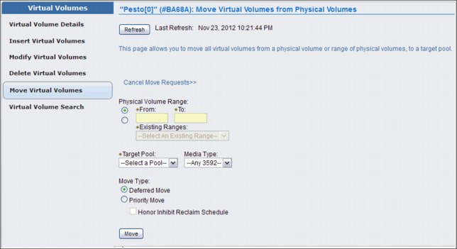
Figure 9-47 MI Move Virtual Volumes
To cancel a move request, select the Cancel Move Requests link. The following options to cancel a move request are available:
•Cancel All Moves: Cancels all move requests.
•Cancel Priority Moves Only: Cancels only priority move requests.
•Cancel Deferred Moves Only: Cancels only Deferred move requests.
•Select a Pool: Cancels move requests from the designated source pool (1 - 32), or from all source pools.
If you want to move virtual volumes, you must define a volume range or select an existing range, select a target pool, and identify a move type:
•Physical Volume Range: The range of physical volumes from where the virtual volumes must be removed. You can use either this option or Existing Ranges to define the range of volumes to move, but not both.
– From: VOLSER of the first physical volume in the range.
– To: VOLSER of the last physical volume in the range.
•Existing Ranges: The list of existing physical volume ranges. You can use either this option or Volume Range to define the range of volumes to move, but not both.
•Media Type: The media type of the physical volumes in the range to move. If no available physical stacked volume of the given media type is in the range specified, no virtual volume is moved.
•Target Pool: The number (1 - 32) of the target pool to which virtual volumes are moved.
•Move Type: Used to determine when the move operation will occur. The following values are possible:
– Deferred: Move operation will occur in the future as schedules permit.
– Priority: Move operation will occur as soon as possible.
– Honor Inhibit Reclaim schedule: An option of the Priority Move Type, it specifies that the move schedule will occur in conjunction with the Inhibit Reclaim schedule. If this option is selected, the move operation will not occur when Reclaim is inhibited.
After you define your move operation parameters and click Move, you will be asked to confirm your request to move the virtual volumes from the defined physical volumes. If you select Cancel, you will return to the Move Virtual Volumes window.
Virtual Volumes Search window
Use the window shown in Figure 9-48 to search for virtual volumes in a specific TS7700 Virtualization Engine Cluster by VOLSER, category, media type, expiration date, or inclusion in a group or class.
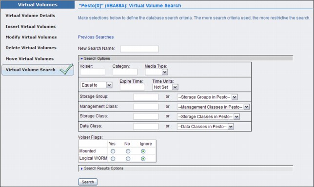
Figure 9-48 MI Virtual Volume Search entry window
You can view the results of a previous query, or create a new query to search for virtual volumes.
|
Tip: Only one search can be executed at a time. If a search is in progress, an information message will occur at the top of the Virtual Volumes Search window. You can cancel a search in progress by clicking Cancel Search.
|
To view the results of a previous search query, select the Previous Searches hyperlink to see a table containing a list of previous queries. Click a query name to display a list of virtual volumes that match the search criteria.
Up to 10 previously named search queries can be saved. To clear the list of saved queries, select the check box adjacent to one or more queries to be removed, select Clear from the drop-down menu, and click Go. This operation will not clear a search query already in progress. You will be asked to confirm your decision to clear the query list. Select OK to clear the list of saved queries, or Cancel to retain the list of queries.
To create a new search query, enter a name for the new query. Enter a value for any of the fields and select Search to initiate a new virtual volume search. The query name, criteria, start time, and end time are saved along with the search results.
To search for a specific VOLSER, enter your parameters in the New Search Name and Volser fields and then click Search.
Figure 9-49 shows an example of the Virtual Volume Search Results window. The result can be printed or downloaded to a spreadsheet for post-processing.

Figure 9-49 Virtual Volume Search Results page
If you are looking for the results of earlier searches, click Previous Searches on the Virtual Volume Search window, shown in Figure 9-48 on page 482.
The entry fields in Figure 9-48 on page 482, where you can enter your Virtual Volume search, are defined:
•Volser: The volume’s serial number. This field can be left blank. You can also use the following wildcard characters in this field:
– Percent sign (%): Represents zero or more characters.
– Asterisk (*): Translated to % (percent). Represents zero or more characters.
– Period (.): Translated to _ (single underscore). Represents one character.
– A single underscore (_): Represents one character.
– Question mark (?): Translated to _ (single underscore). Represents one character.
•Category: The name of the category to which the virtual volume belongs. This value is a four-character hexadecimal string. This field can be left blank. See Table 9-16 for possible values.
Table 9-16 Category values
|
Hexadecimal value
|
Category
|
|
0001 - FEFF
|
General programming use
|
|
FF00
|
Insert
|
|
FF01
|
Insert for Virtual Tape Server (VTS) stacked volumes
|
|
FF03
|
Scratch for VTS stacked volumes
|
|
FF04
|
Private for VTS stacked volumes
|
|
FF05
|
Disaster recovery for VTS stacked volumes
|
|
FF06
|
Disaster recovery for VTS stacked volumes
|
|
FF08
|
VTS stacked volume internal label is unreadable
|
|
FF09
|
Temporary category used by the VTS
|
|
FF10
|
Convenience eject
|
|
FF11
|
High-capacity eject
|
|
FF12
|
Export pending volumes
|
|
FF13
|
Exported volumes
|
|
FF14
|
Import volumes
|
|
FF15
|
Import pending volumes
|
|
FF16
|
Unassigned volumes (VTS import)
|
|
FF17
|
Export-hold volumes
|
|
FF20
|
Volume with corrupted tokens (peer-to-peer VTS usage only)
|
|
FFF4
|
Cleaner volume (Enterprise Tape Cartridge (ETC))
|
|
FFF5
|
Service volume (ETC)
|
|
FFF6
|
Service volume (High Performance Cartridge Tape (HPCT)/Extended High Performance Cartridge Tape (EHCPT))
|
|
FFF9
|
Service volume (Cartridge System Tape (CST)/Enhanced Capacity Cartridge System Tape (ECCST)
|
|
FFFA
|
Manually ejected
|
|
FFFD
|
Cleaner volume (HPCT/EHPCT)
|
|
FFFE
|
Cleaner volume (CST/ECCST)
|
|
FFFF
|
VOLSER specific
|
•Media Type: The type of media on which the volume resides. Use the drop-down menu to select from the available media types. This field can be left blank.
•Expire Time: The amount of time in which virtual volume data will expire. Enter a number. This field is qualified by the values Equal to, Less than, or Greater than in the preceding drop-down menu and defined by the succeeding drop-down menu under the heading Time Units. This field can be left blank.
•Removal Residency: This field is only visible if the selected cluster is a TS7720 (does not attach to a physical library). The residency state of the virtual volume. The following values are possible:
– Blank (ignore): If this field is empty (blank), the search ignores any values in the Removal Residency field. This is the default selection.
– Removed: The search includes only virtual volumes that have been removed.
– Removed Before: The search includes only virtual volumes removed before a specific date and time. If you select this value, you must also complete the fields for Removal Time.
– Removed After: The search includes only virtual volumes removed after a certain date and time. If you select this value, you must also complete the fields for Removal Time.
– In Cache: The search includes only virtual volumes in the cache.
– Retained: The search includes only virtual volumes classified as retained.
– Deferred: The search includes only virtual volumes classified as deferred.
– Held: The search includes only virtual volumes classified as held.
– Pinned: The search includes only virtual volumes classified as pinned.
– No Removal Attempted: The search includes only virtual volumes that have not previously been subject to a removal attempt.
– Removable Before: The search includes only virtual volumes that are candidates for removal before a specific date and time. If you select this value, you must also complete the fields for Removal Time.
– Removable After: The search includes only virtual volumes that are candidates for removal after a specific date and time. If you select this value, you must also complete the fields for Removal Time.
•Removal Time: This field is only visible if the selected cluster does not attach to a physical library.
The date and time that informs the Removed Before, Removed After, Removable Before, and Removable After search queries. These values reflect the time zone in which your browser is located:
– Date: The calendar date according to month (M), day (D), and year (Y); it takes the format: MM/DD/YYYY. This field is accompanied by a date chooser calendar icon. You can enter the month, day, and year manually, or you can use the calendar chooser to select a specific date. The default for this field is blank.
– Time: The Coordinated Universal Time (UTC) in hours (H), minutes (M), and seconds (S). The values in this field must take the form HH:MM:SS. Possible values for this field include 00:00:00 through 23:59:59. This field is accompanied by a time chooser clock icon. You can enter hours and minutes manually using 24-hour time designations, or you can use the time chooser to select a start time based on a 12-hour (AM/PM) clock. The default for this field is midnight (00:00:00).
•Volume Copy Retention Group: The name of the Volume Copy Retention Group for the cluster.
The Volume Copy Retention Group provides additional options to remove data from a disk-only TS7700 Virtualization Engine as the active data reaches full capacity. Volumes become candidates for removal if an appropriate number of copies exist on peer clusters and the volume copy retention time has elapsed since the volume was last accessed. Volumes in each group are removed in order based on their least recently used access times. The volume copy retention time describes the number of hours a volume remains in cache before becoming a candidate for removal.
This field is only visible if the selected cluster is a TS7720 (does not attach to a physical library). The following values are valid:
– Blank (ignore): If this field is empty (blank), the search ignores any values in the Volume Copy Retention Group field. This is the default selection.
– Prefer Remove: Removal candidates in this group are removed prior to removal candidates in the Prefer Keep group.
– Prefer Keep: Removal candidates in this group are removed after removal candidates in the Prefer Remove group.
– Pinned: Copies of volumes in this group are never removed from the accessing cluster. The volume copy retention time does not apply to volumes in this group. Volumes in this group that are subsequently moved to scratch become priority candidates for removal.
|
Tip: Plan when assigning volumes to this group to avoid cache overruns.
|
– “—”: Volume Copy Retention does not apply to the TS7740 cluster. This value (a dash indicating an empty value) is displayed if the cluster attaches to a physical tape library.
•Storage Group: The name of the Storage Group in which the virtual volume resides. You can enter a name in the empty field, or select a name from the adjacent drop-down menu. This field can be left blank.
•Management Class: The name of the Management Class to which the virtual volume belongs. You can enter a name in the empty field, or select a name from the adjacent drop-down menu. This field can be left blank.
•Storage Class: The name of the Storage Class to which the virtual volume belongs. You can enter a name in the empty field, or select a name from the adjacent drop-down menu. This field can be left blank.
•Data Class: The name of the Data Class to which the virtual volume belongs. You can enter a name in the empty field, or select a name from the adjacent drop-down menu. This field can be left blank.
•Mounted: Whether the virtual volume is mounted. The following values are possible:
– Ignore: Ignores any values in the Mounted field. This is the default selection.
– Yes: Includes only mounted virtual volumes.
– No: Includes only unmounted virtual volumes.
•Logical WORM: Whether the logical volume is defined as Write Once Read Many (WORM). The following values are possible:
– Ignore: Ignores any values in the Logical WORM field. This is the default selection.
– Yes: Includes only WORM logical volumes.
– No: Does not include any WORM logical volumes.
|
Remember: You can print or download the results of a search query using “Print Report” or “Download Spreadsheet” on the Volumes found: table at the end of the Search Results window, as shown in Figure 9-49 on page 483.
|
Categories
Use this page to add, modify, or delete a scratch (Fast Ready) category of virtual volumes. You can also use this page to view the total number of volumes defined by custom, inserted, and damaged categories. A category is a grouping of virtual volumes for a pre-defined use. A scratch (Fast Ready) category groups virtual volumes for non-specific use. This grouping enables faster mount times because the IBM Virtualization Engine TS7700 can order category mounts without recalling data from a stacked volume. Figure 9-50 on page 487 shows the Category panel in the TS7700 MI.

Figure 9-50 Categories panel
You can display the already defined categories as shown in the Figure 9-51.
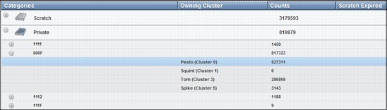
Figure 9-51 Displaying existing categories
Table 9-17 on page 488 describes values displayed on the Categories table as shown in Figure 9-51.
Table 9-17 Category values
|
Column name
|
Description
|
||
|
Categories
|
The type of category that defines the virtual volume. The following values are valid:
•Scratch: Categories within the user-defined private range 0x0001 through 0xEFFF that are defined as scratch (Fast Ready). Click the plus sign (+) icon to expand this heading and reveal the list of categories defined by this type. Expire time and hold values are shown in parentheses next to the category number. See Table 9-16 for descriptions of these values.
•Private: Custom categories established by a user, within the range of 0x0001 - 0xEFFF. Click the plus sign (+) icon to expand this heading and reveal the list of categories defined by this type.
•Damaged: A system category identified by the number 0xFF20. Virtual volumes in this category are considered damaged.
•Insert: A system category identified by the number 0xFF00. Inserted virtual volumes are held in this category until moved by the host into a scratch category.
If no defined categories exist for a certain type, that type is not displayed on the Categories table.
|
||
|
Owning Cluster
|
Names of all clusters in the grid. Expand a category type or number to display. This column is visible only when the accessing cluster is part of a grid.
|
||
|
Counts
|
The total number of virtual volumes according to category type, category, or owning cluster.
|
||
|
Scratch Expired
|
The total number of scratch volumes per owning cluster that are expired. The total of all scratch expired volumes is the number of ready scratch volumes.
|
||
You can use the Categories table to add, modify, or delete a scratch category, or to change the way information is displayed.
|
Tip: The total number of volumes within a grid is not always equal to the sum of all category counts. Some internal categories do not show in the table. Also, volumes can change category multiple times per second, what makes the snapshot count obsolete.
|
Table 9-18 on page 489 describes the actions that can be performed on the Categories page.
Table 9-18 Available actions on the Categories page
|
Action
|
Steps to perform action
|
|
|
Add a scratch category
|
1. Select Add Scratch Category.
2. Define the following category properties:
– Category: A four-digit hexadecimal number that identifies the category. The valid characters for this field are A - F and 0 - 9. Do not use category name 0000 or “FFxx”, where xx equals 0 - 9 or A - F. 0000 represents a null value, and “FFxx” is reserved for hardware.
– Expire: The amount of time after a virtual volume is returned to the scratch (Fast Ready) category before its data content is automatically delete-expired. Select an expiration time from the drop-down menu. If you select No Expiration, volume data never automatically delete-expires. If you select Custom, enter values for the following fields:
• Time: Enter a number in the text field according to these restrictions:
1 - 32,767 if unit is hours
1 - 1,365 if unit is days
1 - 195 if unit is weeks
• Time Unit: Select a corresponding unit from the drop-down menu.
– Set Expire Hold: Check this box to prevent the virtual volume from being mounted or having its category and attributes changed before the expire time has elapsed. Checking this field activates the hold state for any volumes currently in the scratch (Fast Ready) category and for which the expire time has not yet elapsed. Clearing this field removes the access restrictions on all volumes currently in the hold state within this scratch (Fast Ready) category.
|
|
|
Modify a scratch category
|
You can modify a scratch category in two ways:
•Select a category on the table, and then, select Actions → Modify Scratch Category.
•Right-click on a category on the table and either hold, or select Modify Scratch Category from the pop-up menu.
You can modify the following category values:
•Expire
•Set Expire Hold
You can modify one category at a time.
|
|
|
Delete a scratch category
|
You can delete a scratch category in two ways:
1. Select a category on the table, and then, select Actions → Delete Scratch Category.
2. Right-click a category on the table and select Delete Scratch Category from the pop-up menu.
You can delete only one category at a time.
|
|
|
Hide or show columns on the table
|
1. Right-click the table header.
2. Click the check box next to a column heading to hide or show that column in the table. Column headings that are checked display on the table.
|
|
|
Filter the table data
|
Follow these steps to filter using a string of text:
1. Click in the Filter field.
2. Enter a search string.
3. Press Enter.
Follow these steps to filter by column heading:
1. Click the down arrow next to the Filter field.
2. Select the column heading to filter by.
3. Refine the selection:
– Categories: Enter a whole or partial category number and press Enter.
– Owning Cluster: Enter a cluster name or number and press Enter. Expand the category type or category to view highlighted results.
– Counts: Enter a number and press Enter to search on that number string.
– Scratch Expired: Enter a number and press Enter to search on that number string.
|
|
|
Reset the table to its default view
|
1. Right-click the table header.
2. Click Reset Table Preferences.
|
|
9.2.6 The Physical icon
The topics in this section present information related to monitoring and manipulating physical volumes in the TS7740 Virtualization Engine. Use the window shown in Figure 9-52 on page 491 to view or modify settings for physical volume pools to manage the physical volumes used by the TS7740 Virtualization Engine.
If the grid does not possess a physical library, this page is not visible on the TS7700 Virtualization Engine MI.
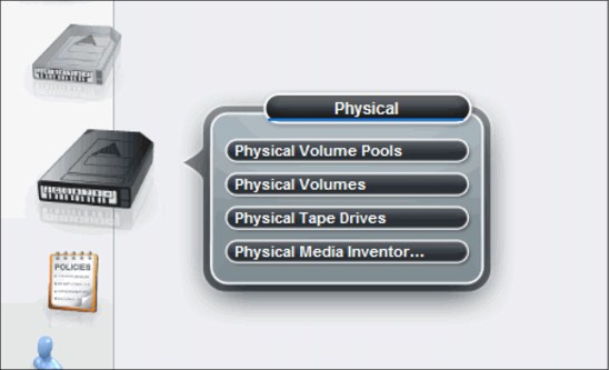
Figure 9-52 Physical icon
Physical Volume Pools
The Physical Volume Pools properties table displays the media properties and encryption settings for every physical volume pool defined for a specific cluster in the grid. This table contains two tabs:
•Pool Properties
•Encryption Settings
|
Tip: Pools 1 - 32 are preinstalled. Pool 1 functions as the default pool and will be used if no other pool is selected. All other pools must be defined before they can be selected.
|
Figure 9-53 on page 492 show an example of the Physical Volume Pools page. There is a link available for a tutorial showing you how to modify pool encryption settings. Click the link to see the tutorial material. This page is visible but disabled on the TS7700 Virtualization Engine MI if the grid possesses a physical library, but the selected cluster does not. The following message is displayed:
The cluster is not attached to a physical tape library.

Figure 9-53 Physical Volume Pools Properties table
Pool Properties tab
The Pool Properties tab displays the properties of the physical volume pools. The following pool information is displayed on this tab:
•Pool: The pool number. This number is a whole number 1 - 32, inclusive.
•Media Class: The supported media class of the storage pool. The valid value is 3592.
•First Media (Primary): The primary media type that the pool can borrow from or return to the common scratch pool (Pool 0). The values displayed in this field are dependent upon the configuration of physical drives in the cluster. See Table 4-2 on page 131 for First and Second Media values based on drive configuration. The following values are possible:
Any 3592 Any media with a 3592 format.
None The only option available if the Primary Media type is any 3592. This option is only valid when the Borrow Indicator field value is No Borrow, Return or No Borrow, Keep.
JA Enterprise Tape Cartridge (ETC)
JB Extended Data Enterprise Tape Cartridge (ETCL)
JC Enterprise Advanced Data Cartridge (EADC)
JJ Enterprise Economy Tape Cartridge (EETC)
JK Enterprise Advanced Economy Tape Cartridge (EAETC)
•Second Media (Secondary): The second choice of media type from which the pool can borrow. Options shown exclude the media type chosen for First Media. The following values are possible:
Any 3592 Any media with a 3592 format.
None The only option available if the Primary Media type is any 3592. This option is only valid when the Borrow Indicator field value is No Borrow, Return or No Borrow, Keep.
JA Enterprise Tape Cartridge (ETC)
JB Extended Data Enterprise Tape Cartridge (ETCL)
JC Enterprise Advanced Data Cartridge (EADC)
JJ Enterprise Economy Tape Cartridge (EETC)
JK Enterprise Advanced Economy Tape Cartridge (EAETC)
•Borrow Indicator: Defines how the pool is populated with scratch cartridges. The following values are possible:
Borrow, Return A cartridge is borrowed from the Common Scratch Pool (CSP) and returned to the CSP when emptied.
Borrow, Keep A cartridge is borrowed from the CSP and retained by the actual pool, even after being emptied.
No Borrow, Return A cartridge is not borrowed from CSP, but an emptied cartridge is placed in CSP. This setting is used for an empty pool.
No Borrow, Keep A cartridge is not borrowed from CSP, and an emptied cartridge is retained in the actual pool.
•Reclaim Pool: The pool to which virtual volumes are assigned when reclamation occurs for the stacked volume on the selected pool.
|
Important: The reclaim pool designated for the Copy Export pool needs to be set to the same value as the Copy Export pool. If the reclaim pool is modified, Copy Export disaster recovery capabilities can be compromised.
|
If there is a need to modify the reclaim pool designated for the Copy Export pool, the reclaim pool must not be set to the same value as the primary pool or the reclaim pool designated for the primary pool. If the reclaim pool for the Copy Export pool is the same as either of the other two pools mentioned, the primary and backup copies of a virtual volume might exist on the same physical media. If the reclaim pool for the Copy Export pool is modified, it is the user’s responsibility to Copy Export volumes from the reclaim pool.
•Maximum Devices: The maximum number of physical tape drives that the pool can use for premigration.
•Export Pool: The type of export supported if the pool is defined as an Export Pool (the pool from which physical volumes are exported). The following values are possible:
Not Defined The pool is not defined as an Export pool.
Copy Export The pool is defined as a Copy Export pool.
•Export Format: The media format used when writing volumes for export. This function can be used when the physical library recovering the volumes supports a different media format than the physical library exporting the volumes. This field is only enabled if the value in the Export Pool field is Copy Export. The following values are valid for this field:
Default The highest common format supported across all drives in the library. This is also the default value for the Export Format field.
E06 Format of a 3592-E06 Tape Drive.
E07 Format of a 3592-E07 Tape Drive.
•Days Before Secure Data Erase: The number of days a physical volume that is a candidate for Secure Data Erase can remain in the pool without access to a physical stacked volume. Each stacked physical volume possesses a timer for this purpose, which is reset when a virtual volume on the stacked physical volume is accessed. Secure Data Erase occurs at a later time, based on an internal schedule. Secure Data Erase renders all data on a physical stacked volume inaccessible. The valid range of possible values is
1 - 365. Clearing the check box deactivates this function.
1 - 365. Clearing the check box deactivates this function.
•Days Without Access: The number of days the pool can persist without access to set a physical stacked volume as a candidate for reclamation. Each physical stacked volume has a timer for this purpose, which is reset when a virtual volume is accessed. The reclamation occurs at a later time, based on an internal schedule. The valid range of possible values is 1 - 365. Clearing the check box deactivates this function.
•Age of Last Data Written: The number of days the pool has persisted without write access to set a physical stacked volume as a candidate for reclamation. Each physical stacked volume has a timer for this purpose, which is reset when a virtual volume is accessed. The reclamation occurs at a later time, based on an internal schedule. The valid range of possible values is 1 - 365. Clearing the check box deactivates this function.
•Days Without Data Inactivation: The number of sequential days that the data ratio of the pool has been higher than the Maximum Active Data used to set a physical stacked volume as a candidate for reclamation. Each physical stacked volume has a timer for this purpose, which is reset when data inactivation occurs. The reclamation occurs at a later time, based on an internal schedule. The valid range of possible values is 1 - 365. Clearing the check box deactivates this function. If deactivated, this field is not used as a criteria for reclaim.
•Maximum Active Data: The ratio of the amount of active data in the entire physical stacked volume capacity. This field is used with Days Without Data Inactivation. The valid range of possible values is 5 - 95%. This function is disabled if Days Without Data Inactivation is not checked.
•Reclaim Threshold: The percentage used to determine when to perform reclamation of free storage on a stacked volume. When the amount of active data on a physical stacked volume drops below this percentage, a reclaim operation is performed on the stacked volume. The valid range of possible values is 0 - 95% and can be selected in 5% increments; 35% is the default value.
To modify pool properties, click the check box next to one or more pools shown on the Pool Properties tab, select Modify Pool Properties from the drop-down menu, and click Go.
Physical Tape Encryption Settings
The Physical Tape Encryption Settings tab displays the encryption settings for physical volume pools. The following encryption information is displayed on this tab:
•Pool: The pool number. This number is a whole number 1 - 32, inclusive.
•Encryption: The encryption state of the pool. The following values are possible:
Enabled Encryption is enabled on the pool.
Disabled Encryption is not enabled on the pool. When this value is selected, key modes, key labels, and check boxes are disabled.
•Key Mode 1: Encryption mode used with Key Label 1. The following values are available:
Clear Label The data key is specified by the key label in clear text.
Hash Label The data key is referenced by a computed value corresponding to its associated public key.
None Key Label 1 is disabled.
“-” The default key is in use.
•Key Label 1: The current encryption key Label 1 for the pool. The label must consist of ASCII characters and cannot exceed 64 characters. Leading and trailing blanks are removed, but an internal space is allowed. Lowercase characters are internally converted to uppercase upon storage; therefore, key labels are reported using uppercase characters.
|
Note: You can use identical values in Key Label 1 and Key Label 2, but you must define each label for each key.
|
If the encryption state is “Disabled”, this field is blank. If the default key is used, the value in this field is “default key”.
•Key Mode 2: Encryption mode used with Key Label 2. The following values are valid:
Clear Label The data key is specified by the key label in clear text.
Hash Label The data key is referenced by a computed value corresponding to its associated public key.
None Key Label 2 is disabled.
“-” The default key is in use.
•Key Label 2: The current encryption Key Label 2 for the pool. The label must consist of ASCII characters and cannot exceed 64 characters. Leading and trailing blanks are removed, but an internal space is allowed. Lowercase characters are internally converted to uppercase upon storage,; therefore, key labels are reported using uppercase characters.
If the encryption state is “Disabled”, this field is blank. If the default key is used, the value in this field is “default key”.
To modify encryption settings, click the check box in the Select column next to one or more pools shown on the Physical Tape Encryption Settings tab, select Modify Encryption Settings from the drop-down menu, and click Go.
Figure 9-54 shows the Modify Encryption Settings panel.

Figure 9-54 Modify Encryption Settings panel
Physical Volumes
The topics in this section present information related to monitoring and manipulating physical volumes in the TS7740 Virtualization Engine. This page is visible but disabled on the TS7700 Virtualization Engine MI if the grid possesses a physical library, but the selected cluster does not.
The following message is displayed:
The cluster is not attached to a physical tape library.
|
Tip: This page is not visible on the TS7700 Virtualization Engine MI if the grid does not possess a physical library.
|
TS7700 Virtualization Engine MI pages collected under the Physical icon can help you view or change settings or actions related to the physical volumes and pools, physical drives, media inventory, TVC, and a physical library. Figure 9-55 shows the navigation and the Physical Volumes page.
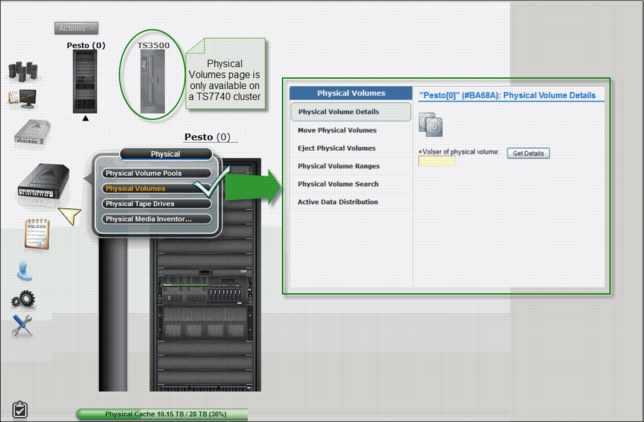
Figure 9-55 Physical Volumes navigation and options
The following options are available selections under Physical Volumes.
Physical Volume Details
Use this page to obtain detailed information about a physical stacked volume in the IBM TS7740 Virtualization Engine. Figure 9-56 on page 497 shows a sample of the Physical Volume Details panel.
You can download the list of virtual volumes in the physical stacked volume being displayed by clicking Download List of Virtual Volumes under the table.

Figure 9-56 Physical Volume Details page
The following information is displayed when details for a physical stacked volume are retrieved:
VOLSER Six-character VOLSER number of the physical stacked volume.
Type The media type of the physical stacked volume. The following values are possible:
JA (ETC) Enterprise Tape Cartridge
JB (ETCL) Enterprise Extended-Length Tape Cartridge
JC (EATC) Enterprise Advanced Tape Cartridge
JJ (EETC) Enterprise Economy Tape Cartridge
JK (EAETC) Enterprise Advanced Economy Tape Cartridge
|
Note: JC (EATC) and JK (EAETC) media types are only available if the highest common format (HCF) is set to E07 or higher.
|
Recording Format The format used to write the media. The following values are possible:
Undefined The recording format used by the volume is not recognized as a supported format.
J1A
E05
E05E E05 with Encryption
E06
E06E E06 with Encryption
E07
E07E E07 with Encryption
Volume State The following values are possible:
Read-Only The volume is in a read-only state.
Read/Write The volume is in a read/write state.
Unavailable The volume is in use by another task or is in a pending eject state.
Destroyed The volume is damaged and unusable for mounting.
Copy Export Pending
The volume is in a pool that is being exported as part of an in-progress Copy Export.
The volume is in a pool that is being exported as part of an in-progress Copy Export.
Copy Exported The volume has been ejected from the library and removed to offsite storage.
Copy Export Reclaim
The host can send a Host Console Query request to reclaim a physical volume currently marked Copy Exported. The data mover will then reclaim the virtual volumes from the primary copies.
The host can send a Host Console Query request to reclaim a physical volume currently marked Copy Exported. The data mover will then reclaim the virtual volumes from the primary copies.
Copy Export No Files Good
The physical volume has been ejected from the library and removed to offsite storage. The virtual volumes located on that physical volume are obsolete.
The physical volume has been ejected from the library and removed to offsite storage. The virtual volumes located on that physical volume are obsolete.
Misplaced The library cannot locate the specified volume.
Inaccessible The volume exists in the library inventory but is currently in a location that the cartridge accessor cannot access.
Manually Ejected The volume was previously present in the library inventory, but cannot currently be located.
Capacity State Possible values are empty, filling, and full.
Key Label 1/Key Label 2
The encryption key label that is associated with a physical volume. Up to two key labels can be present. If there are no labels present, the volume is not encrypted. If the encryption key used is the default key, the value in this field is “default key”.
The encryption key label that is associated with a physical volume. Up to two key labels can be present. If there are no labels present, the volume is not encrypted. If the encryption key used is the default key, the value in this field is “default key”.
Encrypted Time The date the physical volume was first encrypted using the new encryption key. If the volume is not encrypted, the value in this field is “-”.
Home Pool The pool number to which the physical volume was assigned when it was inserted into the library, or the pool to which it was moved through the library manager Move/Eject Stacked Volumes function.
Current Pool The current storage pool in which the physical volume resides.
Mount Count The number of times the physical volume has been mounted since being inserted into the library.
Virtual Volumes Contained
Number of virtual volumes contained on this physical stacked volume.
Number of virtual volumes contained on this physical stacked volume.
Pending Actions Whether a move or eject operation is pending. The following values are possible:
Pending Eject
Pending Priority Eject
Pending Deferred Eject
Pending Move to Pool #
Where # represents the destination pool.
Where # represents the destination pool.
Pending Priority Move to Pool #
Where # represents the destination pool.
Where # represents the destination pool.
Pending Deferred Move to Pool #
Where # represents the destination pool.
Where # represents the destination pool.
Copy Export Recovery
Whether the database backup name is valid and can be used for recovery. Possible values are Yes and No.
Whether the database backup name is valid and can be used for recovery. Possible values are Yes and No.
Database Backup The time stamp portion of the database backup name.
Move Physical Volumes
Use this page to move a range or quantity of physical volumes used by the IBM TS7740 Virtualization Engine to a target pool, or cancel a previous move request.
Figure 9-57 shows the panel.

Figure 9-57 Move Physical Volumes options
The Select Move Action menu provides options for moving physical volumes to a target pool. The following options are available to move physical volumes to a target pool:
Move Range of Physical Volumes
Moves to the target pool physical volumes in the specified range. This option requires you to select a Volume Range, Target Pool, and Move Type. You can also select a Media Type.
Moves to the target pool physical volumes in the specified range. This option requires you to select a Volume Range, Target Pool, and Move Type. You can also select a Media Type.
Move Range of Scratch Only Volumes
Moves to the target pool scratch volumes in the specified range. This option requires you to select a Volume Range and Target Pool. You can also select a Media Type.
Moves to the target pool scratch volumes in the specified range. This option requires you to select a Volume Range and Target Pool. You can also select a Media Type.
Move Quantity of Scratch Only Volumes
Moves a specified quantity of physical volumes from the source pool to the target pool. This option requires you to select Number of Volumes, Source Pool, and Target Pool. You can also select a Media Type.
Moves a specified quantity of physical volumes from the source pool to the target pool. This option requires you to select Number of Volumes, Source Pool, and Target Pool. You can also select a Media Type.
Move Export Hold to Private
Moves all Copy Export volumes in a source pool back to a private category if the volumes are in the Export/Hold category but have not yet been selected to be ejected from the library. This option requires you to select a Source Pool.
Moves all Copy Export volumes in a source pool back to a private category if the volumes are in the Export/Hold category but have not yet been selected to be ejected from the library. This option requires you to select a Source Pool.
Cancel Move Requests Cancels any previous move request.
If you select Move Range of Physical Volumes or Move Range of Scratch Only Volumes from the Select Move Action menu, you are asked to define a volume range or select an existing range, select a target pool, and identify a move type. You can also select a media type.
If you select Move Quantity of Scratch Only Volumes from the Select Move Action menu, you are asked to define the number of volumes to be moved, identify a source pool, and identify a target pool. You can also select a media type.
If you select Move Export Hold to Private from the Select Move Action menu, you are asked to identify a source pool.
The following move operation parameters are available:
Volume Range The range of physical volumes to move. You can use either this option or the Existing Ranges option to define the range of volumes to move, but not both. Specify the range:
To VOLSER of the first physical volume in the range to move.
From VOLSER of the last physical volume in the range to move.
Existing Ranges The list of existing physical volume ranges. You can use either this option or the Volume Range option to define the range of volumes to move, but not both.
Source Pool The number (0 - 32) of the source pool from which physical volumes are moved. If you are selecting a source pool for a Move Export Hold to Private operation, the range of volumes displayed is 1 - 32.
Target Pool The number (0 - 32) of the target pool to which physical volumes are moved.
Move Type Used to determine when the move operation will occur. The following values are possible:
Deferred Move Move operation will occur based on the first Reclamation policy triggered for the applied source pool. This operation is dependent on reclaim policies for the source pool and might take some time to complete.
Priority Move Move operation will occur as soon as possible. Use this option if you want the operation to complete sooner.
Honor Inhibit Reclaim schedule
An option of the Priority Move Type, it specifies that the move schedule will occur in conjunction with Inhibit Reclaim schedule. If this option is selected, the move operation will not occur when Reclaim is inhibited.
An option of the Priority Move Type, it specifies that the move schedule will occur in conjunction with Inhibit Reclaim schedule. If this option is selected, the move operation will not occur when Reclaim is inhibited.
Number of Volumes The number of physical volumes to be moved.
Media Type Specifies the media type of the physical volumes in the range to be moved. The physical volumes in the range specified to move must be of the media type designated by this field, or else the move operation will fail.
After you define your move operation parameters and click Move, you are asked to confirm your request to move physical volumes. If you select Cancel, you will return to the Move Physical Volumes page. To cancel a previous move request, select Cancel Move Requests from the Select Move Action menu. The following options are available to cancel a move request:
Cancel All Moves Cancels all move requests.
Cancel Priority Moves Only
Cancels only priority move requests.
Cancels only priority move requests.
Cancel Deferred Moves Only
Cancels only deferred move requests.
Cancels only deferred move requests.
Select a Pool Cancels move requests from the designated source pool (0 - 32), or from all source pools.
Eject physical volumes
Use this page to eject a range or quantity of physical volumes used by the IBM TS7740 Virtualization Engine or to cancel a previous eject request.
Figure 9-58 show the Eject Physical Volumes panel.

Figure 9-58 Eject Physical Volumes panel
The Select Eject Action menu provides options for ejecting physical volumes.
|
Note: Before a stacked volume with active virtual volumes can be ejected, all active logical volumes in it will be copied to a different stacked volume.
|
The following options are available to eject physical volumes:
Eject Range of Physical Volumes
Ejects physical volumes in the range specified. This option requires you to select a volume range and eject type. You can also select a media type.
Ejects physical volumes in the range specified. This option requires you to select a volume range and eject type. You can also select a media type.
Eject Range of Scratch Only Volumes
Ejects scratch volumes in the range specified. This option requires you to select a volume range. You can also select a media type.
Ejects scratch volumes in the range specified. This option requires you to select a volume range. You can also select a media type.
Eject Quantity of Scratch Only Volumes
Ejects a specified quantity of physical volumes. This option requires you to select a number of volumes and a source pool. you can also select a media type.
Ejects a specified quantity of physical volumes. This option requires you to select a number of volumes and a source pool. you can also select a media type.
Eject Export Hold Volumes
Ejects a subset of the volumes in the Export/Hold Category.
Ejects a subset of the volumes in the Export/Hold Category.
Eject Empty Unsupported Media
Ejects physical volumes on unsupported media after the existing read-only data is migrated to new media.
Ejects physical volumes on unsupported media after the existing read-only data is migrated to new media.
Cancel Eject Requests
Cancels any previous eject request.
Cancels any previous eject request.
If you select “Eject Range of Physical Volumes” or “Eject Range of Scratch Only Volumes” from the Select Eject Action menu, you will be asked to define a volume range or select an existing range and identify an eject type. You can also select a media type.
If you select “Eject Quantity of Scratch Only Volumes” from the Select Eject Action menu, you will be asked to define the number of volumes to be ejected, and to identify a source pool. You can also select a media type.
If you select “Eject Export Hold Volumes” from the Select Eject Action menu, you will be asked to select the VOLSERs of the volumes to be ejected. To select all VOLSERs in the Export Hold category, select Select All from the drop-down menu. The eject operation parameters include these parameters:
Volume Range The range of physical volumes to eject. You can use either this option or the Existing Ranges option to define the range of volumes to eject, but not both. Define the range:
To VOLSER of the first physical volume in the range to eject.
From VOLSER of the last physical volume in the range to eject.
Existing Ranges The list of existing physical volume ranges. You can use either this option or the Volume Range option to define the range of volumes to eject, but not both.
Eject Type Used to determine when the eject operation will occur. The following values are possible:
Deferred Eject Eject operation will occur based on the first Reclamation policy triggered for the applied source pool. This operation is dependent on reclaim policies for the source pool and can take some time to complete.
Priority Eject Eject operation will occur as soon as possible. Use this option if you want the operation to complete sooner.
Honor Inhibit Reclaim schedule
An option of the Priority Eject Type, it specifies that the eject schedule will occur in conjunction with the Inhibit Reclaim schedule. If this option is selected, the eject operation will not occur when Reclaim is inhibited.
An option of the Priority Eject Type, it specifies that the eject schedule will occur in conjunction with the Inhibit Reclaim schedule. If this option is selected, the eject operation will not occur when Reclaim is inhibited.
Number of Volumes The number of physical volumes to be ejected.
Source Pool The number (0 - 32) of the source pool from which physical volumes are ejected.
Media Type Specifies the media type of the physical volumes in the range to be ejected. The physical volumes in the range specified to eject must be of the media type designated by this field, or else the eject operation will fail.
After you define your eject operation parameters and click Eject, you are asked to confirm your request to eject physical volumes. If you select Cancel, you will return to the Eject Physical Volumes page.
To cancel a previous eject request, select Cancel Eject Requests from the Select Eject Action menu. The following options are available to cancel an eject request:
Cancel All Ejects Cancels all eject requests.
Cancel Priority Ejects Only
Cancels only priority eject requests.
Cancels only priority eject requests.
Cancel Deferred Ejects Only
Cancels only deferred eject requests.
Cancels only deferred eject requests.
Physical Volume Ranges page
Use this page to view physical volume ranges or unassigned physical volumes in a library attached to an IBM TS7740 Virtualization Engine.
Figure 9-59 shows the Physical Volume Ranges panel and options. When working with volumes recently added to the attached TS3500 Tape Library that are not showing in the Physical Volume Ranges panel, click Inventory Upload. This action requests the physical inventory from the defined logical library in the TS3500 to be uploaded to the TS7740, repopulating the Physical Volume Ranges panel.
|
Tip: When inserting a VOLSER that belongs to a defined TS7740 range, it will be presented and inventoried according to the setup in place. If the newly inserted VOLSER does not belong to any defined range in the TS7740, an intervention-required message is generated, requiring the user to correct the assignment for this VOLSER.
|

Figure 9-59 Physical Volume Ranges panel
|
Important: If a physical volume range contains virtual volumes with active data, those virtual volumes must be moved or deleted before the physical volume range can be moved or deleted.
|
The following information is displayed in the Physical Volume Ranges table:
Start VOLSER The first VOLSER in a defined range.
End VOLSER The last VOLSER in a defined range.
Media Type The media type for all volumes in a given VOLSER range. The following values are possible:
JA-ETC Enterprise Tape Cartridge
JB-ETCL Enterprise Extended-Length Tape Cartridge
JC-EADC Enterprise Advanced Data Cartridge
JJ-EETC Enterprise Economy Tape Cartridge
JK-EAETC Enterprise Advanced Economy Tape Cartridge
|
Note: JA and JJ media are only supported for read-only operations with 3592 E07 Tape Drives.
|
Home Pool The home pool to which the VOLSER range is assigned.
Use the drop-down menu on the Physical Volume Ranges table to add a new VOLSER range or to modify or delete a pre-defined range.
Unassigned Volumes
The Unassigned Volumes table displays for a given cluster the list of unassigned physical volumes that are pending ejection. A VOLSER is removed from this table when a new range that contains the VOLSER is added. The following status information is displayed in the Unassigned Volumes table:
VOLSER The VOLSER associated with a given physical volume.
Media Type The media type for all volumes in a given VOLSER range. The following values are possible:
JA-ETC Enterprise Tape Cartridge
JB-ETCL Enterprise Extended-Length Tape Cartridge
JC-EADC Enterprise Advanced Data Cartridge
JJ-EETC Enterprise Economy Tape Cartridge
JK-EAETC Enterprise Advanced Economy Tape Cartridge
|
Note: JA and JJ media are only supported for read-only operations with 3592 E07 Tape Drives.
|
Pending Eject Whether the physical volume associated with the given VOLSER is awaiting ejection.
Use the Unassigned Volumes table to eject one or more physical volumes from a library attached to a TS7740 Virtualization Engine.
Physical volume search
Use this page to search for physical volumes in a given IBM TS7740 Virtualization Engine cluster according to one or more identifying features.
Figure 9-60 shows the Physical Volume Search panel. You can click the Previous Searches hyperlink to view the results of a previous query on the new page Previous Physical Volumes Searches.

Figure 9-60 Physical Volume Search panel
The following information can be seen and requested on the Physical Volume Search panel:
New Search Name Use this field to create a new search query.
Enter a name for the new query in the New Search Name field.
Enter values for any of the search parameters defined in the Search Options table.
Search Options Use this table to define the parameters for a new search query.
Click the down arrow adjacent to Search Options to open the Search Options table.
|
Note: Only one search can be executed at a time. If a search is in progress, an information message displays at the top of the Physical Volume Search page. You can cancel a search in progress by clicking “Cancel Search” within this message.
|
Define one or more of the following search parameters:
VOLSER The volume serial number. This field can be left blank. You can also use the following wildcard characters in this field:
% (percent) Represents zero or more characters.
* (asterisk) Is translated to % (percent). Represents zero or more characters.
. (period) Represents one character.
_ (single underscore)
Is translated to . (period). Represents one character.
Is translated to . (period). Represents one character.
? (question mark)
Is translated to. (period). Represents one character.
Is translated to. (period). Represents one character.
Media Type The type of media on which the volume resides. Use the drop-down menu to select from available media types. This field can be left blank. The following other values are possible:
JA Enterprise Tape Cartridge (ETC)
JC Enterprise Advanced Data Cartridge (EADC)
JB Extended Data Enterprise Tape Cartridge (ETCL)
JJ Enterprise Economy Tape Cartridge (EETC)
JK Enterprise Advanced Economy Tape Cartridge (EAETC)
Recording Format The format used to write the media. Use the drop-down menu to select from available media types. This field can be left blank. The following other values are possible:
Undefined The recording format used by the volume is not recognized as a supported format.
J1A
E05
E05E E05 with Encryption.
E06
E06E E06 with Encryption.
E07
E07E E07 with Encryption.
Capacity State Whether any active data exists on the physical volume and the status of that data in relation to the volume’s capacity. This field can be left blank. The following other values are valid:
Empty The volume contains no data and is available for use as a physical scratch volume.
Filling The volume contains valid data, but is not yet full. It is available for additional data.
Full The volume contains valid data. At some point, it was marked as full and additional data cannot be added to it. In some cases, a volume can be marked full and yet be short of the volume capacity limit.
Enter a name for the new query in the New Search Name field. Enter values for any of the search parameters defined in the Search Options table.
Search Options table
Use this table to define the parameters for a new search query. Click the down arrow adjacent to Search Options to open the Search Options table.
|
Note: Only one search can be executed at a time. If a search is in progress, an information message displays at the top of the Physical Volume Search page. You can cancel a search in progress by clicking “Cancel Search” within this message.
|
Define one or more of the following search parameters:
VOLSER The volume serial number. This field can be left blank. You can also use the following wildcard characters in this field:
% (percent) Represents zero or more characters.
* (asterisk) Is translated to % (percent). Represents zero or more characters.
. (period) Represents one character.
_ (single underscore)
Is translated to . (period). Represents one character.
? (question mark)
Is translated to . (period). Represents one character.
Media Type The type of media on which the volume resides. Use the drop-down menu to select from available media types. This field can be left blank. The following other values are possible:
JA Enterprise Tape Cartridge (ETC)
JC Enterprise Advanced Data Cartridge (EADC)
JB Extended Data Enterprise Tape Cartridge (ETCL)
JJ Enterprise Economy Tape Cartridge (EETC)
JK Enterprise Advanced Economy Tape Cartridge (EAETC)
Recording Format The format used to write the media. Use the drop-down menu to select from available media types. This field can be left blank. The following other values are possible:
Undefined The recording format used by the volume is not recognized as a supported format.
J1A
E05
E05E E05 with Encryption.
E06
E06E E06 with Encryption.
E07
E07E E07 with Encryption.
Capacity State Whether any active data exists on the physical volume and the status of that data in relation to the volume’s capacity. This field can be left blank. The following other values are possible:
Empty The volume contains no data and is available for use as a physical scratch volume.
Filling The volume contains valid data, but is not yet full. It is available for additional data.
Full The volume contains valid data. At some point, it was marked as full and additional data cannot be added to it. In some cases, a volume can be marked full and yet be short of the volume capacity limit.
Home Pool The pool number (0 - 32) to which the physical volume was assigned when it was inserted into the library, or the pool to which it was moved through the library manager Move/Eject Stacked Volumes function. This field can be left blank.
Current Pool The number of the storage pool (0 - 32) in which the physical volume currently resides. This field can be left blank.
Encryption Key The encryption key label designated when the volume was encrypted. This is a text field. The following values are valid:
– A name identical to the first or second key label on a physical volume.
– Any physical volume encrypted using the designated key label is included in the search.
– Search for the default key. Select this check box to search for all physical volumes encrypted using the default key label.
Pending Eject Whether to include physical volumes pending an eject in the search query. The following values are valid:
All Ejects All physical volumes pending eject are included in the search.
Priority Ejects Only physical volumes classified as priority eject are included in the search.
Deferred Ejects Only physical volumes classified as deferred eject are included in the search.
Pending Move to Pool
Whether to include physical volumes pending a move in the search query. The following values are possible:
Whether to include physical volumes pending a move in the search query. The following values are possible:
All Moves All physical volumes pending a move are included in the search.
Priority Moves Only physical volumes classified as priority move are included in the search.
Deferred Moves Only physical volumes classified as deferred move are included in the search.
Any of the previous values can be modified by using the adjacent drop-down menu. Use the adjacent drop-down menu to narrow your search to a specific pool set to receive physical volumes. The following values are possible:
– All Pools: All pools are included in the search.
– 0 - 32: The number of the pool to which the selected physical volumes are moved.
VOLSER flags Whether to include, exclude, or ignore any of the following VOLSER flags in the search query. Select only one: Yes to include, No to exclude, or Ignore to ignore the following VOLSER types during the search:
– Misplaced
– Mounted
– Inaccessible
– Encrypted
– Export Hold
– Read Only Recovery
– Unavailable
– Pending Secure Data Erase
– Copy Exported
Search Results Options
Use this table to select the properties displayed on the Physical Volume Search Results page.
Click the down arrow adjacent to Search Results Options to open the Search Results Options table. Select the check box adjacent to each property that you want to display on the Physical Volume Search Results page.
Review the property definitions from the Search Options table section. The following properties can be displayed on the Physical Volume Search Results page:
•Media Type
•Recording Format
•Home Pool
•Current Pool
•Pending Actions
•Volume State
•Mounted Tape Drive
•Encryption Key Labels
•Export Hold
•Read Only Recovery
•Copy Export Recovery
•Database Backup
Click Search to initiate a new physical volume search. After the search is initiated but before it completes, the Physical Volume Search page displays the following information message:
The search is currently in progress. You can check the progress of the search on the Previous Search Results page.
|
Note: The search-in-progress message is displayed on the Physical Volume Search page until the in-progress search completes or is canceled.
|
Figure 9-61 on page 510 shows the result of a search.

Figure 9-61 Physical Volume Search Results page
To check the progress of the search being executed, click the Previous Search Results hyperlink in the information message. To cancel a search in progress, click “Cancel Search”. When the search completes, the results are displayed in the Physical Volume Search Results page. The query name, criteria, start time, and end time are saved along with the search results. You can save a maximum of 10 search queries.
Active Data Distribution page
Use this page to view the distribution of data on physical volumes marked full on an IBM TS7740 Virtualization Engine Cluster. The distribution can be used to select an appropriate reclaim threshold.
The Active Data Distribution page displays the percent utilization of physical volumes in increments of 10%. Figure 9-62 shows the Active Data Distribution page.

Figure 9-62 Active Data Distribution panel
Number of Full Volumes at Utilization Percentages
The tables in Figure 9-63 on page 511 show the number of physical volumes marked as full in each physical volume pool, according to percentage of volume used. The following fields are displayed:
Pool The physical volume pool number. This number is a hyperlink; click it to display a graphical representation of the number of physical volumes per utilization increment in a given pool. When you click the pool number hyperlink, the Active Data Distribution subpage opens.
Figure 9-63 on page 511 shows a sample of the subpage you see by clicking on the pool 4 hyperlink.

Figure 9-63 Active Data Distribution for a specific pool
This subpage contains the following fields and information:
Pool To view graphical information for another pool, select the target pool from this drop-down menu.
Current Reclaim Threshold
The percentage used to determine when to perform reclamation of free storage on a stacked volume. When the amount of active data on a physical stacked volume drops under this percentage, a reclaim operation is performed on the stacked volume. The valid range of possible values is 0 - 95% and can be selected in 5% increments; 35% is the default value.
The percentage used to determine when to perform reclamation of free storage on a stacked volume. When the amount of active data on a physical stacked volume drops under this percentage, a reclaim operation is performed on the stacked volume. The valid range of possible values is 0 - 95% and can be selected in 5% increments; 35% is the default value.
|
Tip: This percentage is a hyperlink; click it to open the Modify Pool Properties page, where you can modify the percentage used for this threshold.
|
Number of Volumes with Active Data
The number of physical volumes that contain active data.
The number of physical volumes that contain active data.
Pool n Active Data Distribution
This graph displays the number of volumes that contain active data per volume utilization increment for the selected pool. On this graph, utilization increments (x axis) do not overlap.
This graph displays the number of volumes that contain active data per volume utilization increment for the selected pool. On this graph, utilization increments (x axis) do not overlap.
Pool n Active Data Distribution (cumulative)
This graph displays the cumulative number of volumes that contain active data per volume utilization increment for the selected pool. On this graph, utilization increments (x axis) overlap, accumulating as they increase.
This graph displays the cumulative number of volumes that contain active data per volume utilization increment for the selected pool. On this graph, utilization increments (x axis) overlap, accumulating as they increase.
The Active Data Distribution subpage also displays utilization percentages for the selected pool, excerpted from the Number of Full Volumes at Utilization Percentages table.
Media Type The type of cartridges contained in the physical volume pool. If more than one media type exists in the pool, each type is displayed, separated by commas. The following values are possible:
Any 3592 Any media with a 3592 format
JA Enterprise Tape Cartridge (ETC)
JB Extended Data Enterprise Tape Cartridge (ETCL)
JC Enterprise Advanced Data Cartridge (EADC)
JJ Enterprise Economy Tape Cartridge (EETC)
JK Enterprise Advanced Economy Tape Cartridge (EAETC)
Percentage of Volume Used (0+, 10+, 20+, and so on)
Each of the last 10 columns in the table represents a 10% increment of total physical volume space used. For instance, the column heading 20+ represents the 20% - 29% range of a physical volume used. For each pool, the total number of physical volumes that occur in each range is listed.
Each of the last 10 columns in the table represents a 10% increment of total physical volume space used. For instance, the column heading 20+ represents the 20% - 29% range of a physical volume used. For each pool, the total number of physical volumes that occur in each range is listed.
Physical Tape Drives
Use this page to view a summary of the state of all physical drives accessible to the IBM TS7740 Virtualization Engine Cluster.
This page is visible but disabled on the TS7700 Virtualization Engine MI if the grid possesses a physical library, but the selected cluster does not. The following message is displayed:
The cluster is not attached to a physical tape library.
|
Tip: This page is not visible on the TS7700 Virtualization Engine MI if the grid does not possess a physical library.
|
Figure 9-64 on page 513 shows the Physical Tape Drives page.

Figure 9-64 Physical Tape Drives page
The Physical Tape Drives table displays status information for all physical drives accessible by the cluster, including the following information:
Serial Number The serial number of the physical drive.
Drive Type The machine type and model number of the drive. The following values are possible:
3592J1A
3592E05
3592E05E A 3592 E05 drive that is encryption capable.
3592E06
3952E07
Online Whether the drive is currently online.
Health The health of the physical drive. This value is obtained automatically at times determined by the TS7700 Virtualization Engine. The following values are possible:
OK The drive is fully functioning.
WARNING The drive is functioning but reporting errors. Action needs to be taken to correct the errors.
DEGRADED The drive is operational but has lost some redundancy resource and performance.
FAILURE The drive is not functioning and immediate action must be taken to correct it.
OFFLINE/TIMEOUT The drive is out of service or unreachable within a certain time frame.
Role The current role the drive is performing. The following values are possible:
IDLE The drive is currently not in use.
MIGRATION The drive is being used to copy a virtual volume from the TVC to the physical volume.
RECALL The drive is being used to recall a virtual volume from a physical volume to the TVC.
RECLAIM SOURCE The drive is being used as the source of a reclaim operation.
RECLAIM TARGET The drive is being used as the target of a reclaim operation.
EXPORT The drive is currently being used to export a volume.
SECURE ERASE The drive is being used to erase expired volumes from the physical volume securely and permanently.
Mounted Physical Volume
VOLSER of the physical volume mounted by the drive.
VOLSER of the physical volume mounted by the drive.
Recording Format The format in which the drive operates. The following values are possible:
J1A The drive is operating with J1A data.
E05 The drive is operating with E05 data.
E05E The drive is operating with E05E encrypted data.
E06 The drive is operating with E06 data.
E06E The drive is operating with E06E encrypted data.
E07 The drive is operating with E07 data.
E07E The drive is operating with E07E encrypted data.
Not Available The format is unable to be determined because there is no physical media in the drive or the media is being erased.
Unavailable The format is unable to be determined because the Health and Monitoring checks have not yet completed. Refresh the current page to determine whether the format state has changed. If the Unknown state persists for one hour or longer, contact your IBM SSR.
Requested Physical Volume
The VOLSER of the physical volume requested for mount. If no physical volume is requested, this field is blank.
The VOLSER of the physical volume requested for mount. If no physical volume is requested, this field is blank.
To view additional information for a specific, selected drive, see the Physical Drives Details table on the Physical Tape Drive Details page:
1. Click the radio button next to the serial number of the physical drive in question.
2. Select Details from the Select Action drop-down menu.
3. Click Go to open the Physical Tape Drives Details page.
Figure 9-65 on page 515 shows a Physical Tape Drive Details page.
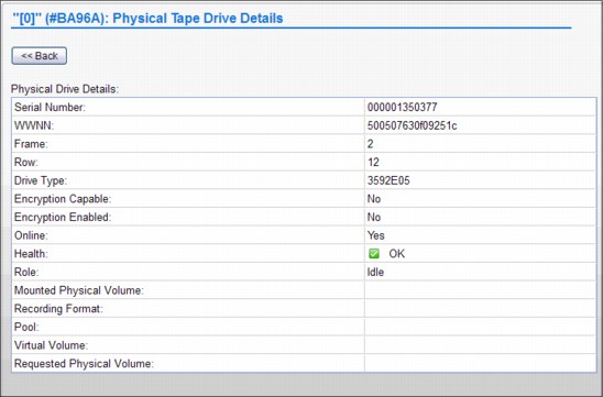
Figure 9-65 Physical Tape Drive Details page
The Physical Drives Details table displays detailed information for a specific physical tape drive:
Serial Number The serial number of the physical drive.
Drive Type The machine type and model number of the drive. The following values are possible:
3592J1A
3592E05
3592E05E A 3592 E05 drive that is encryption capable.
3592E06
3952E07
Online Whether the drive is currently online.
Health The health of the physical drive. This value is obtained automatically at times determined by the TS7740 Virtualization Engine. The following values are possible:
OK The drive is fully functioning.
WARNING The drive is functioning but reporting errors. Action needs to be taken to correct the errors.
DEGRADED The drive is functioning but at lesser redundancy and performance.
FAILURE The drive is not functioning and immediate action must be taken to correct it.
OFFLINE/TIMEOUT The drive is out of service or cannot be reached within a certain time frame.
Role The current role that the drive is performing. The following values are possible:
IDLE The drive is currently not in use.
MIGRATION The drive is being used to copy a virtual volume from the TVC to the physical volume.
RECALL The drive is being used to recall a virtual volume from a physical volume to the TVC.
RECLAIM SOURCE The drive is being used as the source of a reclaim operation.
RECLAIM TARGET The drive is being used as the target of a reclaim operation.
EXPORT The drive is currently being used to export a volume.
SECURE ERASE The drive is being used to erase expired volumes from the physical volume securely and permanently.
Mounted Physical Volume
VOLSER of the physical volume mounted by the drive.
VOLSER of the physical volume mounted by the drive.
Recording Format The format in which the drive operates. The following values are possible:
J1A The drive is operating with J1A data.
E05 The drive is operating with E05 data.
E05E The drive is operating with E05E encrypted data.
E06 The drive is operating with E06 data.
E06E The drive is operating with E06E encrypted data.
E07 The drive is operating with E07 data.
E07E The drive is operating with E07E encrypted data.
Not Available The format is unable to be determined because there is no physical media in the drive or the media is being erased.
Unavailable The format is unable to be determined because the Health and Monitoring checks have not yet completed. Refresh the current page to determine whether the format state has changed. If the Unknown state persists for one hour or longer, contact your IBM SSR.
Requested Physical Volume
The VOLSER of the physical volume requested for mount. If no physical volume is requested, this field is blank.
The VOLSER of the physical volume requested for mount. If no physical volume is requested, this field is blank.
WWNN The worldwide node name used to locate the drive.
Frame The frame in which the drive resides.
Row The row in which the drive resides.
Encryption Enabled Whether encryption is enabled on the drive.
|
Note: If you are monitoring this field while changing the encryption status of a drive, the new status will not display until you bring the TS7700 Cluster offline and then return it to an online state.
|
Encryption Capable Whether the drive is capable of encryption.
Physical Volume VOLSER of the physical volume mounted by the drive.
Pool The pool name of the physical volume mounted by the drive.
Virtual Volume VOLSER of the virtual volume being processed by the drive.
Click Back to return to the Physical Tape Drives page.
Physical Media Inventory
Use this page to view physical media counts for media types in storage pools in the IBM Virtualization Engine TS7700.
This page is visible but disabled on the TS7700 Virtualization Engine MI if the grid possesses a physical library, but the selected cluster does not. The following message is displayed:
The cluster is not attached to a physical tape library.
|
Tip: This page is not visible on the TS7700 Virtualization Engine MI if the grid does not possess a physical library.
|
Figure 9-66 shows the Physical Media Inventory page.

Figure 9-66 Physical Media Inventory page
The following physical media counts are displayed for each media type in each storage pool:
Pool The storage pool number.
Media Type The media type defined for the pool. A storage pool can have multiple media types and each media type will be displayed separately. The following values are possible:
JA Enterprise Tape Cartridge (ETC)
JB Extended Data Enterprise Tape Cartridge (ETCL)
JC Enterprise Advanced Data Cartridge (EADC)
JJ Enterprise Economy Tape Cartridge (EETC)
JK Enterprise Advanced Economy Tape Cartridge (EAETC)
Empty The count of physical volumes that are empty for the pool.
Filling The count of physical volumes that are filling for the pool. This field is blank for pool 0.
Full The count of physical volumes that are full for the pool. This field is blank for pool 0.
|
Tip: A value in this field is displayed as a hyperlink; click it to open the Active Data Distribution subpage. The Active Data Distribution subpage displays a graphical representation of the number of physical volumes per utilization increment in a given pool. If no full volumes exist, the hyperlink is disabled.
|
Queued for Erase The count of physical volumes that are reclaimed but need to be erased before they can become empty. This field is blank for pool 0.
ROR The count of physical volumes in the Read Only Recovery (ROR) state that are damaged or corrupted.
Unavailable The count of physical volumes that are in the unavailable or destroyed state.
Unsupported Unsupported media (for example: JA and JJ) type present in tape library and inserted for the TS7740. Based on the drive configuration, the TS7700 cannot use one or more of the specified media, which can result in the out-of-scratch condition.
9.2.7 The Constructs icon
The topics in this section present information that is related to TS7700 Virtualization Engine storage constructs. Figure 9-67 shows you the Constructs icon and the options under it.

Figure 9-67 The Constructs icon
Storage Groups window
Use the window shown in Figure 9-68 to add, modify, or delete a Storage Group.

Figure 9-68 MI Storage Groups window
The Storage Groups table displays all existing Storage Groups available for a given cluster.
You can use the Storage Groups table to create a new Storage Group, modify an existing Storage Group, or delete a Storage Group. Also, you can copy selected Storage Groups to the other clusters in this grid by using the “Copy to Clusters” action available in the drop-down menu.
The Storage Groups table shows the following status information:
Name The name of the Storage Group. Each Storage Group within a cluster must have a unique name. Valid characters for this field are A - Z, 0 - 9, $, @, *, #, and %.
Primary Pool The primary pool for migration. Only validated physical primary pools can be selected. If the cluster does not possess a physical library, this column will not be visible and the MI categorizes newly created Storage Groups using pool 1.
Description A description of the Storage Group.
Use the drop-down menu in the Storage Groups table to add a new Storage Group or modify or delete an existing Storage Group.
To add a new Storage Group, select Add from the drop-down menu. Complete the fields for information that will be displayed in the Storage Groups table.
|
Restriction: If the cluster does not possess a physical library, the Primary Pool field will not be available in the Add or Modify options.
|
To modify an existing Storage Group, select the radio button from the Select column that appears adjacent to the name of the Storage Group that you want to modify. Select Modify from the drop-down menu. Complete the fields for information that will be displayed in the Storage Groups table.
To delete an existing Storage Group, select the radio button from the Select column that appears adjacent to the name of the Storage Group you want to delete. Select Delete from the drop-down menu. You will be prompted to confirm your decision to delete a Storage Group. If you select OK, the Storage Group will be deleted. If you select No, your request to delete will be canceled.
Management Classes window
Use this window (Figure 9-69) to define, modify, copy, or delete the Management Class that defines the TS7700 Virtualization Engine copy policy for volume redundancy. The table displays the copy policy in force for each component of the grid.
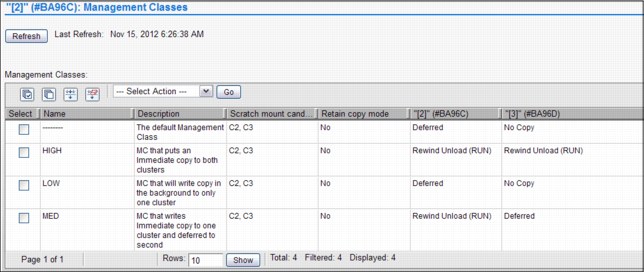
Figure 9-69 MI Management Classes window on a grid
The Management Classes window for a grid with a physical library has an additional column showing the possibility of a secondary copy pool. This is a requirement for using the Copy Export function.
Figure 9-70 displays Management Classes with a secondary pool defined.

Figure 9-70 Management Class with secondary pool
You can use the Management Classes table to create a new Management Class, modify an existing Management Class, or delete one or more existing Management Classes. The default Management Class can be modified, but cannot be deleted. The default Management Class uses dashes (--------) for the symbolic name.
The Management Classes table shows the following status information:
Name The name of the Management Class. Valid characters for this field are A - Z, 0 - 9, $, @, *, #, and %. The first character of this field cannot be a number. This is the only field that cannot be modified after it is added.
Secondary Pool The target pool in the volume duplication. If the cluster does not possess a physical library, this column will not be visible and the MI categorizes newly created Storage Groups using pool 0.
Description A description of the Management Class definition. The value in this field must be from 1 to 70 characters in length.
Retain Copy Mode Whether previous copy policy settings on private (non-Fast Ready) logical volume mounts are retained.
Retain Copy mode prevents the copy modes of a logical volume from being refreshed by an accessing host device if the accessing cluster is not the same cluster that created the volume. When Retain Copy mode is enabled through the MI, previously assigned copy modes are retained and subsequent read or modify access does not refresh, update, or merge copy modes. This allows the original number of copies to be maintained.
Scratch Mount Candidate
This indicates whether this cluster is allowed to select scratch candidates from the volumes residing in this Management Class.
This indicates whether this cluster is allowed to select scratch candidates from the volumes residing in this Management Class.
Use the drop-down menu on the Management Classes table to add a new Management Class, modify an existing Management Class, copy an existing Management Class, or delete one or more existing Management Classes.
To add a new Management Class, select Add from the drop-down menu and click Go. Complete the fields for information that will be displayed in the Management Classes table. You can create up to 256 Management Classes per TS7700 Virtualization Engine Grid.
|
Remember: If the cluster does not possess a physical library, the Secondary Pool field will not be available in the “Add” option.
|
The Copy Action drop-down option allows you to copy any existing Management Class to each cluster in the TS7700 Virtualization Engine Grid.
The following options are available in the Management Class:
No Copy No volume duplication will occur if this action is selected.
Rewind Unload (RUN)
Volume duplication occurs when the Rewind Unload command is received. The command will only return after the volume duplication completes successfully.
Volume duplication occurs when the Rewind Unload command is received. The command will only return after the volume duplication completes successfully.
Deferred Volume duplication occurs at a later time based on the internal schedule of the copy engine.
Synchronous Copy Volume duplication is treated as host I/O and will take place before control is returned to the application issuing the I/O. Only two clusters in the grid can have the Synchronous mode copy defined.
To modify an existing Management Class, check the check box from the Select column that appears in the same row as the name of the Management Class that you want to modify. You can modify only one Management Class at a time. Select Modify from the drop-down menu and click Go. Of the fields listed previously in the Management Classes table, you will be able to change all of them, except the Management Class name.
|
Remember: If the cluster does not possess a physical library, the Secondary Pool field will not be available in the Modify option.
|
To delete one or more existing Management Classes, check the check box from the Select column that appears in the same row as the name of the Management Class that you want to delete. Check multiple check boxes to delete multiple Management Classes. Select Delete from the drop-down menu, and click Go.
|
Restriction: You will not be permitted to delete the default Management Class.
|
Storage Classes window
Use the window shown in Figure 9-71 to define, modify, or delete a Storage Class used by the TS7700 Virtualization Engine to automate storage management through classification of data sets and objects.

Figure 9-71 MI Storage Classes window on a TS7740
The Storage Classes table lists defined storage classes that are available to control data sets and objects within a cluster.
You can use the Storage Classes table to create a new Storage Class, or modify or delete an existing Storage Class. The default Storage Class can be modified, but cannot be deleted. The default Storage Class has dashes (--------) as the symbolic name.
The Storage Classes table displays the following status information:
Name The name of the Storage Class. Valid characters for this field are A - Z, 0 - 9, $, @, *, #, and %. The first character of this field cannot be a number. The value in this field must be between 1 and 8 characters in length.
Tape Volume Cache Preference
The preference level for the Storage Class, which determines how soon volumes are removed from cache following their copy to tape. The following values are possible:
The preference level for the Storage Class, which determines how soon volumes are removed from cache following their copy to tape. The following values are possible:
Use IART Volumes are removed according to the TS7700 Virtualization Engine’s Initial Access Response Time (IART).
Level 0 Volumes are removed from the TVC as soon as they are copied to tape.
Level 1 Copied volumes remain in the TVC until additional space is required, then the first volumes are removed to free up space in the cache.
Description A description of the Storage Class definition. The value in this field must be between 1 and 70 characters in length.
Use the drop-down menu in the Storage Classes table to add a new Storage Class, or modify or delete an existing Storage Class.
To add a new Storage Class, select Add from the drop-down menu. Complete the fields for the information that will be displayed in the Storage Classes table.
|
Tip: You can create up to 256 Storage Classes per TS7700 Virtualization Engine Grid.
|
To modify an existing Storage Class, select the radio button from the Select column that appears in the same row as the name of the Storage Class that you want to modify. Select Modify from the drop-down menu. Of the fields listed in the Storage Classes table, you will be able to change all of them, except the Storage Class name.
To delete an existing Storage Class, select the radio button from the Select column that appears in the same row as the name of the Storage Class that you want to delete. Select Delete from the drop-down menu. A window opens to confirm the Storage Class deletion. Select OK to delete the Storage Class, or No to cancel the delete request.
The Storage Class construct for a TS7720 has different settings as shown in Figure 9-72.

Figure 9-72 MI Storage Class for TS7720
The Storage Classes table for TS7720 displays the following status information:
Name The name of the storage class. Valid characters for this field are A - Z, 0 - 9, $, @, *, #, and %. The first character of this field cannot be a number. The value in this field must be between 1 and 8 characters in length.
Volume Copy Retention Group
This group provides additional options to remove data from a disk-only TS7700 Virtualization Engine as the active data reaches full capacity:
This group provides additional options to remove data from a disk-only TS7700 Virtualization Engine as the active data reaches full capacity:
Prefer Remove Removal candidates in this group are removed before removal candidates in the Prefer Keep group.
Prefer Keep Removal candidates in this group are removed after removal candidates in the Prefer Remove group.
Pinned Copies of volumes in this group are never removed from the accessing cluster.
Volume Copy Retention Time
The minimum amount of time after a logical volume copy was last accessed that the copy can be removed from cache. Set the value in hours.
The minimum amount of time after a logical volume copy was last accessed that the copy can be removed from cache. Set the value in hours.
Description A description of the ss definition. The value in this field must be between 1 and 70 characters in length.
Data Classes window
Use the window shown in Figure 9-73 to define, modify, or delete a TS7700 Virtualization Engine Data Class used to automate storage management through the classification of data sets.
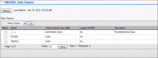
Figure 9-73 MI Data Classes window
|
Important: Scratch (Fast Ready) categories and Data Classes work at the system level and are unique for all clusters in a grid. Therefore, if you modify them on one cluster, they will be applied to all clusters in the grid.
|
The Data Classes table (Figure 9-73) displays the list of Data Classes defined for each cluster of the grid.
You can use the Data Classes table to create a new Data Class or modify or delete an existing Data Class. The default Data Class can be modified, but cannot be deleted. The default Data Class has dashes (--------) as the symbolic name.
The Data Classes table lists the following status information:
Name The name of the Data Class. Valid characters for this field are A - Z,
0 - 9, $, @, *, #, and %. The first character of this field cannot be a number. The value in this field must be between 1 and 8 characters in length.
0 - 9, $, @, *, #, and %. The first character of this field cannot be a number. The value in this field must be between 1 and 8 characters in length.
Virtual Volume Size (MiB)
The logical volume size of the Data Class, which determines the maximum number of MiB for each logical volume in a defined class. One possible value is Insert Media Class, where the logical volume size is not defined (the Data Class will not be defined by a maximum logical volume size). Other possible values are 1,000 MiB, 2,000 MiB, 4,000 MiB, or 6,000 MiB.
The logical volume size of the Data Class, which determines the maximum number of MiB for each logical volume in a defined class. One possible value is Insert Media Class, where the logical volume size is not defined (the Data Class will not be defined by a maximum logical volume size). Other possible values are 1,000 MiB, 2,000 MiB, 4,000 MiB, or 6,000 MiB.
Description A description of the Data Class definition. The value in this field must be at least 0 and no greater than 70 characters in length.
Logical WORM Whether logical WORM is set for the Data Class. Logical WORM is the virtual equivalent of WORM tape media, achieved through software emulation. This setting is available only when all clusters in a grid operate at R1.6 and later.
The following values are valid:
Yes Logical WORM is set for the Data Class. Volumes belonging to the Data Class are defined as logical WORM.
No Logical WORM is not set. Volumes belonging to the Data Class are not defined as logical WORM. This is the default value for a new Data Class.
Use the drop-down menu in the Data Classes table to add a new Data Class, or modify or delete an existing Data Class.
To add a new Data Class, select Add from the drop-down menu and click Go. Complete the fields for information that will be displayed in the Data Classes table.
|
Tip: You can create up to 256 Data Classes per TS7700 Virtualization Engine Grid.
|
To modify an existing Data Class, select the radio button from the Select column that appears in the same row as the name of the Data Class that you want to modify. Select Modify from the drop-down menu and click Go. Of the fields listed in the Data Classes table, you will be able to change all of them, except the default Data Class name.
To delete an existing Data Class, select the radio button from the Select column that appears in the same row as the name of the Data Class you want to delete. Select Delete from the drop-down menu and click Go. A window opens to confirm the Data Class deletion. Select OK to delete the Data Class or No to cancel the delete request.
9.2.8 The Access icon
The topics in this section present information that is related to managing user access in a TS7700 Virtualization Engine. A series of enhancements in user access management has been created. TS7700 Virtualization Engine Release 1.6 introduced a centrally managed, Role-based Access Control (RBAC) policy that authenticated and authorized users using the System Storage Productivity Center (SSPC) to authenticate users to an LDAP server.
Beginning with Release 3.0 of LIC, the TS7700 Virtualization Engine can authenticate users directly to an LDAP server, not depending on an SSPC as an intermediary. Authenticating through an SSPC is still supported. In the current implementation, the TS7700 Virtualization Engine supports LDAP on a Microsoft Active Directory (AD) platform.
Another major difference introduced with Release 3.0 regarding user access control is that the RBAC policies, if activated, apply to all users, through all access ports to the TS7700. Therefore, if centrally managed RBAC is applied, either with SSPC or direct to the LDAP server, no one can log in to the TS7700 Virtualization Engine without being authenticated and authorized by the LDAP server. Even a local IBM SSR, operating from the TS3000 System Console (TSSC), is required to use the LDAP-defined service login. This also applies to remote support, via a telephone line or Assist On-site (AOS) session.
|
Note: Before Release 3.0 (from R1.6 to R2.1), RBAC policies only applied to the MI.
|
Three methods of managing user authentication policy are available with Release 3.0. They provide the option to use a locally administered authentication policy or the centralized RBAC method using an externally managed Storage Authentication Service policy. Centralized RBAC can be configured using an available System Storage Productivity Center (SSPC) or Tivoli Storage Productivity Center, or the authentication can be directly to an LDAP (Microsoft Active Director platform) server.
|
Important: Before enabling Storage Authentication or Direct LDAP policies, create an account that can be used by service personnel (local and remote).
|
Local Authentication Policy is managed and applied within the cluster or clusters participating in a grid. In a multicluster grid configuration, user IDs and their associated roles are defined through the MI on one of the clusters. The user IDs and roles are then propagated through the grid to all participating clusters.
Storage Authentication Service and Direct LDAP policies allow you to centrally manage user IDs and roles:
•The Storage Authentication Service policy stores user and group data on a separate server and maps relationships among users, groups, and authorization roles when a user signs in to a cluster. Network connectivity to an external System Storage Productivity Center (SSPC) is required. Each cluster in a grid can operate its own Storage Authentication Service policy.
•Direct LDAP policy is an RBAC policy that authenticates and authorizes users through direct communication with an LDAP (Microsoft Active Director platform) server. Only one authentication policy can be enabled per cluster at one time.
You can access the following options through the User Access (blue man icon) link:
Security Settings Use this window to view security settings for a TS7700 Virtualization Engine Grid. From this page, you can also access windows to add, modify, assign, test, and delete security settings.
Roles and Permissions
Use this window to set and control user roles and permissions for a TS7700 Virtualization Engine Grid.
Use this window to set and control user roles and permissions for a TS7700 Virtualization Engine Grid.
SSL Certificates Use this window to view, import, or delete Secure Sockets Layer (SSL) certificates to support connection to a Storage Authentication Service server from a TS7700 Virtualization Engine Cluster.
InfoCenter Settings Use this page to upload a new TS7700 Virtualization Engine Information Center to the cluster’s MI.
The options for User Access Management in the MI for TS7700 Virtualization Engine are shown in Figure 9-74.

Figure 9-74 TS7700 Virtualization Engine User Access Management options
Security Settings
Figure 9-75 on page 529 shows the Security Settings window, which is the entry point to enabling security policies.

Figure 9-75 TS7700 Security Settings
Use the Session Timeout policy to specify the number of hours and minutes that the MI can be idle before the current session expires and the user is redirected to the login page. This setting is valid for all users in the grid.
To modify the maximum idle time, select values from the Hours and Minutes drop-down menus and click Submit Changes. The following parameters are valid for Hours and Minutes:
Hours The number of hours the MI can be idle before the current session expires. Possible values for this field are 00 - 23.
Minutes The number of minutes the MI can be idle before the current session expires. Possible values for this field are 00 - 55, selected in five-minute increments.
The Authentication Policies table shown in Figure 9-76 on page 531 lists the following information:
Policy Name The name of the policy that defines the authentication settings. The policy name is a unique value composed of 1 - 50 Unicode characters. Heading and trailing blank spaces are trimmed, although internal blank spaces are permitted. After a new authentication policy has been created, its policy name cannot be modified.
|
Tip: The Local Policy name is Local and cannot be modified.
|
Type The policy type, which can be one of the following values:
Local A policy that replicates authorization based on user accounts and assigned roles. It is the default authentication policy. When enabled, it is enforced for all clusters in the grid. If Storage Authentication Service is enabled, the Local policy is disabled. This policy can be modified to add, change, or delete individual accounts, but the policy itself cannot be deleted.
Storage Authentication Service
A policy that maps user, group, and role relationships upon user login. Each cluster in a grid can operate its own Storage Authentication Service policy by means of assignment. However, only one authentication policy can be enabled on any particular cluster within the grid, even if the same policy is used within other clusters of the same grid domain. A Storage Authentication Service policy can be modified, but can only be deleted if it is not in use on any cluster in the grid.
A policy that maps user, group, and role relationships upon user login. Each cluster in a grid can operate its own Storage Authentication Service policy by means of assignment. However, only one authentication policy can be enabled on any particular cluster within the grid, even if the same policy is used within other clusters of the same grid domain. A Storage Authentication Service policy can be modified, but can only be deleted if it is not in use on any cluster in the grid.
Clusters The clusters for which the authentication policy is in force.
Adding a new user to the Local Authentication Policy
A Local Authentication Policy replicates authorization based on user accounts and assigned roles. It is the default authentication policy. This section looks at the various windows required to manage the Local Authentication Policy.
To add a user to the Local Authentication Policy for a TS7700 Virtualization Engine Grid, perform the following steps:
1. On the TS7700 Virtualization Engine MI, select Access → Security Settings from the left navigation window.
2. Click Select next to the Local policy name on the Authentication Policies table.
3. Select Modify from the Select Action drop-down menu and click Go.
4. On the Local Accounts table, select Add from the Select Action drop-down menu and click Go.
5. In the Add User window, enter values for the following required fields:
– Username: The new user’s login name. This value must be 1 - 128 characters in length and composed of Unicode characters. Spaces and tabs are not allowed.
– Role: The role assigned to the user account. The role can a predefined role or a user-defined role. The following values are possible:
• Operator: The operator has access to monitoring information, but is restricted from changing settings for performance, network configuration, feature licenses, user accounts, and custom roles. The operator is also restricted from inserting and deleting logical volumes.
• Lead Operator: The lead operator has access to monitoring information and can perform actions for a volume operation. The lead operator has nearly identical permissions to the administrator, but may not change network configuration, feature licenses, user accounts, or custom roles.
• Administrator: The administrator has the highest level of authority, and may view all pages and perform any action, including the addition and removal of user accounts. The administrator has access to all service functions and TS7700 Virtualization Engine resources.
• Manager: The manager has access to monitoring information, and performance data and functions, and may perform actions for users, including adding, modifying, and deleting user accounts. The manager is restricted from changing most other settings, including those for logical volume management, network configuration, feature licenses, and custom roles.
• Custom roles: The administrator can name and define two custom roles by selecting the individual tasks permitted to each custom role. Tasks can be assigned to a custom role in the Roles and assigned permissions table in the Roles & Permissions Properties window.
– Cluster Access: The clusters to which the user has access. A user can have access to multiple clusters.
6. To complete the operation, click OK. To abandon the operation and return to the Modify Local Accounts page, click Cancel.
Figure 9-76 shows the first window for creating a new user. It is used for managing users with the Local Authentication Policy method.

Figure 9-76 Creating a new user (part 1of 2)
Figure 9-77 shows the second window for creating a new user.

Figure 9-77 Creating a new user (part 2 of 2)
Modifying the user or group of the Local Authentication Policy
Use this window to modify a user or group property for a TS7700 Virtualization Engine Grid.
|
Tip: Passwords for the users are changed from this window also.
|
To modify a user account belonging to the Local Authentication Policy, perform these steps:
1. On the TS7700 Virtualization Engine MI, select Access (blue man icon) → Security Settings from the left navigation panel. See Figure 9-77 and Figure 9-76 on page 531 for the MI panels.
2. Click Select next to the Local policy name on the Authentication Policies table.
3. Select Modify from the Select Action drop-down menu and click Go.
4. On the Local Accounts table, click Select next to the Username of the policy that you want to modify.
5. Select Modify from the Select Action drop-down menu and click Go. See Figure 9-77 for the Modify Local Accounts options.
6. Modify the values for any of the following fields:
– Role: The role assigned to the user account. The following values are possible:
• Operator: The operator has access to monitoring information, but is restricted from changing settings for performance, network configuration, feature licenses, user accounts, and custom roles. The operator is also restricted from inserting and deleting logical volumes.
• Lead Operator: The lead operator has access to monitoring information and can perform actions for volume operation. The lead operator has nearly identical permissions to the administrator, but may not change network configuration, feature licenses, user accounts, and custom roles.
• Administrator: The administrator has the highest level of authority, and may view all pages and perform any action, including the addition and removal of user accounts. The administrator has access to all service functions and TS7700 Virtualization Engine resources.
• Manager: The manager has access to monitoring information and performance data and functions, and may perform actions for users, including adding, modifying, and deleting user accounts. The manager is restricted from changing most other settings, including those for logical volume management, network configuration, feature licenses, and custom roles.
• Custom roles: The administrator can name and define two custom roles by selecting the individual tasks permitted to each custom role. Tasks can be assigned to a custom role in the Roles and assigned permissions table from the Roles & Permissions Properties window.
– Cluster Access: The clusters to which the user has access. A user can have access to multiple clusters.
7. To complete the operation, click OK. To abandon the operation and return to the Modify Local Accounts page, click Cancel.
|
Restriction: You cannot modify the Username or Group Name. Only the role and the clusters to which it is applied can be modified.
|
The Modify Local Account window is shown in Figure 9-77 on page 532. In the Cluster Access table, you can use the Select check box to toggle all the cluster check boxes on and off.
Adding a Storage Authentication Service policy
A Storage Authentication Service Policy maps user, group, and role relationships upon user login with the assistance of a System Storage Productivity Center (SSPC). This section highlights the various windows required to manage the Storage Authentication Service Policy.
|
Important: When a Storage Authentication Service policy is enabled for a cluster, service personnel are required to log in with the setup user or group. Before enabling storage authentication, create an account that can be used by service personnel.
|
To add a new Storage Authentication Service Policy for a TS7700 Virtualization Engine Grid, perform the following steps:
1. On the TS7700 Virtualization Engine MI, select Access (blue man icon) → Security Settings from the left navigation window.
2. On the Authentication Policies table, select Add Storage Authentication Service Policy from the Select Action drop-down menu.
3. Click Go to open the Add Storage Authentication Service Policy window shown in Figure 9-78 on page 534. The following fields are available for completion:
a. Policy Name: The name of the policy that defines the authentication settings. The policy name is a unique value composed of 1 - 50 Unicode characters. Heading and trailing blank spaces are trimmed, although internal blank spaces are permitted. After a new authentication policy has been created, its policy name cannot be modified.
b. Primary Server URL: The primary URL for the Storage Authentication Service. The value in this field consists of 1 - 256 Unicode characters and takes the following format:
https://<server_IP_address>:secure_port/TokenService/services/Trust
c. Alternate Server URL: The alternate URL for the Storage Authentication Service if the primary URL cannot be accessed. The value in this field consists of 1 - 256 Unicode characters and takes the following format:
https://<server_IP_address>:secure_port/TokenService/services/Trust
|
Remember: If the Primary or Alternate Server URL uses the HTTPS protocol, a certificate for that address must be defined on the SSL Certificates page.
|
d. Server Authentication: Values in the following fields are required if IBM WebSphere Application Server security is enabled on the WebSphere Application Server that is hosting the Authentication Service. If WebSphere Application Server security is disabled, the following fields are optional:
• User ID: The user name used with HTTP basic authentication for authenticating to the Storage Authentication Service.
• Password: The password used with HTTP basic authentication for authenticating to the Storage Authentication Service.
4. To complete the operation, click OK. To abandon the operation and return to the Security Settings page, click Cancel.
Figure 9-78 shows an example of a completed Add Storage Authentication Service Policy window.

Figure 9-78 Add Storage Authentication Service Policy
After you click OK to confirm the creation of the new Storage Authentication Policy, the window shown in Figure 9-79 opens. In the Authentication Policies table, no clusters are assigned to the newly created policy; therefore, the Local Authentication Policy is enforced. When the newly created policy is in this state, it can be deleted because it is not applied to any of the clusters.

Figure 9-79 Addition of Storage Authentication Service Policy completed
Adding a user to a Storage Authentication Policy
To add a new user to a Storage Authentication Service Policy for a TS7700 Virtualization Engine Grid, perform the following steps:
1. On the TS7700 Virtualization Engine MI, select Access → Security Settings from the left navigation window.
2. In the Authentication Policies table, select Modify from the Select Action drop-down menu as shown in Figure 9-80 on page 536.
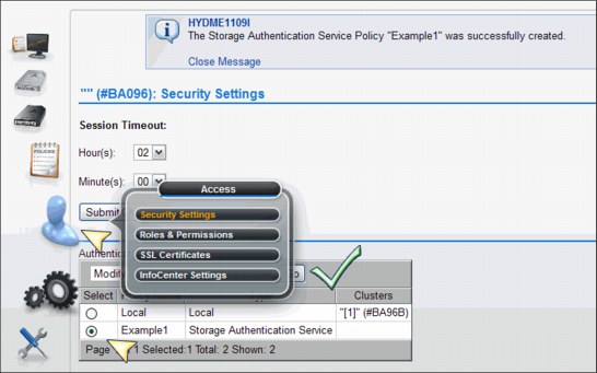
Figure 9-80 Selecting Modify Security Settings
3. Click Go to open the Modify Storage Authentication Service Policy window shown in Figure 9-81 on page 537.

Figure 9-81 Adding a User to the Storage Authentication Service Policy
4. In the Modify Storage Authentication Service Policy window in Figure 9-81, navigate to the Storage Authentication Service Users/Groups table at the bottom.
5. Select Add User from the Select Action drop-down menu.
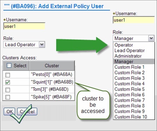
Figure 9-82 Defining Username, Role, and Cluster Access permissions
7. In the Add Storage Authentication Service User window, enter values for the following required fields:
– Username: The new user’s login name. This value must be 1 - 128 characters in length and composed of Unicode characters. Spaces and tabs are not allowed.
– Role: The role assigned to the user account. The role can be a predefined role or a user-defined role. The following values are valid:
• Operator: The operator has access to monitoring information, but is restricted from changing settings for performance, network configuration, feature licenses, user accounts, and custom roles. The operator is also restricted from inserting and deleting logical volumes.
• Lead Operator: The lead operator has access to monitoring information and can perform actions for a volume operation. The lead operator has nearly identical permissions as the administrator, but may not change network configuration, feature licenses, user accounts, and custom roles.
• Administrator: The administrator has the highest level of authority, and may view all pages and perform any action, including the addition and removal of user accounts. The administrator has access to all service functions and TS7700 Virtualization Engine resources.
• Manager: The manager has access to monitoring information and performance data and functions, and may perform actions for users, including adding, modifying, and deleting user accounts. The manager is restricted from changing most other settings, including those for logical volume management, network configuration, feature licenses, and custom roles.
• Custom roles: The administrator can name and define two custom roles by selecting the individual tasks permitted to each custom role. Tasks can be assigned to a custom role in the Roles and assigned permissions table in the Roles & Permissions Properties window.
– Cluster Access: The clusters to which the user has access. A user can have access to multiple clusters.
8. To complete the operation, click OK. To abandon the operation and return to the Modify Local Accounts page, click Cancel.
9. Click OK after the fields are complete. A user is added to the Storage Authentication Service Policy as shown in Figure 9-83.

Figure 9-83 Successful addition of user name to Storage Authentication Service Policy
Assigning clusters to a Storage Authentication Policy
Clusters participating in a multicluster grid can have unique Storage Authentication policies active. To assign an authentication policy to one or more clusters, you must have authorization to modify authentication privileges under the new policy. To verify that you have sufficient privileges with the new policy, you must enter a user name and password recognized by the new authentication policy.
To add a new user to a Storage Authentication Service Policy for a TS7700 Virtualization Engine Grid, perform the following steps:
1. On the TS7700 Virtualization Engine MI, select Access → Security Settings from the left navigation window.
2. In the Authentication Policies table, select Assign from the Select Action drop-down menu as shown in Figure 9-84.

Figure 9-84 Assigning Storage Authentication Service Policy to grid resources
4. To apply the authentication policy to a cluster, select the check box next to the cluster’s name.
Enter values for the following fields:
– User Name: Your user name for the TS7700 Virtualization Engine MI.
– Password: Your password for the TS7700 Virtualization Engine MI.
.
Figure 9-85 Cluster assignment selection for Storage Authentication Service Policy
5. To complete the operation, click OK. To abandon the operation and return to the Security Settings window, click Cancel.
Deleting a Storage Authentication Policy
You can delete a Storage Authentication Service policy if it is not in force on any cluster. You cannot delete the Local policy. In the Authentication Policies table in Figure 9-86 on page 542, no clusters are assigned to the policy to be deleted, and therefore, the policy can be deleted. If clusters are assigned to the policy, use Modify from the Select Action drop-down menu to remove the assigned clusters.

Figure 9-86 Deleting a Storage Authentication Service Policy
To delete a Storage Authentication Service Policy from a TS7700 Virtualization Engine Grid, perform the following steps:
1. On the TS7700 Virtualization Engine MI, select Access → Security Settings from the left navigation window.
2. In the Authentication Policies table, select Delete from the Select Action drop-down menu as shown in Figure 9-86. From the Security Settings page, navigate to the Authentication Policies table and perform the following steps:
a. Select the radio button next to the policy you want to delete.
b. Select Delete from the Select Action drop-down menu.
c. Click Go to open the Confirm Delete Storage Authentication Service policy page.
d. Click OK to delete the policy and return to the Security Settings window, or click Cancel to abandon the delete operation and return to the Security Settings window.
You will be asked to confirm the policy deletion, as shown in Figure 9-87 on page 543. Click OK, and the policy is deleted.

Figure 9-87 Confirm delete and delete action successful messages
Testing an Authentication Policy
Before a new Authentication Policy can be used, it must be tested. The test will validate the login credentials (user ID and password) in all clusters for which this user ID and role are authorized. Also, access to the external resources needed by an external authentication policy, such as an SSPC or an LDAP server, will be tested. The credentials entered in the test panel (User ID and Password) will be authenticated and validated by the LDAP server, for an external policy.
|
Tip: The policy needs to be configured to an LDAP server before being added in the TS7700 MI. External users and groups to be mapped by the new policy are checked in LDAP before being actually added.
|
Follow the procedure described next to test the security settings for the IBM Virtualization Engine TS7700 Grid. Use these steps to test the roles assigned to your user name by an existing policy:
1. From the Security Settings page, navigate to the Authentication Policies table:
– Select the radio button next to the policy that you want to test.
– Select Test from the Select Action drop-down menu.
– Click Go to open the Test Authentication Policy page.
2. Check the check box next to the name of each cluster on which to conduct the policy test.
3. Enter values for the following fields:
– User Name: Your user name for the TS7700 Virtualization Engine MI. This value consists of 1 - 16 Unicode characters.
– Password: Your password for the TS7700 Virtualization Engine MI. This value consists of 1- 16 Unicode characters.
|
Note: If the User Name entered belongs to a user not included on the policy, test results will show success but the result comments will show a null value for the role and access fields. Additionally, the User Name entered cannot be used to log in to the MI.
|
4. Click OK to complete the operation. If you want to abandon the operation, click Cancel to return to the Security Settings page.
When the authentication policy test completes, the Test Authentication Policy results window opens to display results for each selected cluster. See Figure 9-88 for an example.

Figure 9-88 Test Authentication Policy results
The results include a statement indicating whether the test succeeded or failed, and if it failed, the reason for the failure. The Test Authentication Policy results window also displays the Policy Users table. Information shown on that table includes the following fields:
Username The name of a user authorized by the selected authentication policy.
Role The role assigned to the user under the selected authentication policy.
Cluster Access A list of all the clusters in the grid for which the user and user role are authorized by the selected authentication policy. Check Figure 9-89 for an example of a failure in the Test Authentication Policy.

Figure 9-89 Failure in the Test Authentication Policy
To return to the Test Authentication Policy window, click Close Window. To return to the Security Settings page, click Back at the top of the Test Authentication Policy results window.
Adding a Direct LDAP policy
A Direct LDAP Policy is an external policy that maps user, group, and role relationships. Users are authenticated and authorized through a direct communication with an LDAP server. This section highlights the various windows required to manage a Direct LDAP policy.
|
Important: When a Direct LDAP policy is enabled for a cluster, service personnel are required to log in with the setup user or group. Before enabling LDAP authentication, create an account that can be used by service personnel.
|
To add a new Direct LDAP Policy for a TS7700 Virtualization Engine Grid, perform the following steps:
1. On the TS7700 Virtualization Engine MI, select Access → Security Settings from the left navigation window.
2. From the pull-down menu, select Add Direct LDAP Policy and click GO. Use Figure 9-90 for reference.

Figure 9-90 Adding a Direct LDAP Policy
The panel in Figure 9-91 on page 546 is shown.

Figure 9-91 Adding a Direct LDAP Policy
|
Note: LDAP external authentication policies not available for backup or recovery through the backup or restore settings operations. Record it, keep it safe, and have it available for a manual recovery as recommended by your security standards.
|
The values in the following fields are required if secure authentication is used or anonymous connections are disabled on the LDAP server:
•User Distinguished Name: The user distinguished name is used to authenticate to the LDAP authentication service. This field supports a maximum length of 254 Unicode characters, for example:
CN=Administrator,CN=users,DC=mycompany,DC=com
•Password: The password is used to authenticate to the LDAP authentication service. This field supports a maximum length of 254 Unicode characters.
If you selected to modify an LDAP Policy, you can also make changes to any of these LDAP attributes fields:
•Base Distinguish Name: The LDAP distinguished name (DN) that uniquely identifies a set of entries in a realm. This field is required but blank by default. The value in this field consists of 1 - 254 Unicode characters.
•Username Attribute: The attribute name used for the username during authentication. This field is required and contains the value uid by default. The value in this field consists of 1 - 61 Unicode characters.
•Password: The attribute name used for the password during authentication. This field is required and contains the value userPassword by default. The value in this field consists of 1 - 61 Unicode characters.
•Group Member Attribute: The attribute name used to identify group members. This field is optional and contains the value member by default. This field can contain up to 61 Unicode characters.
•Group Name Attribute: The attribute name used to identify the group during authorization. This field is optional and contains the value cn by default. This field can contain up to 61 Unicode characters.
•User Name filter: Used to filter and verify the validity of an entered username. This field is optional and contains the value (uid={0}) by default. This field can contain up to 254 Unicode characters.
•Group Name filter: Used to filter and verify the validity of an entered group name. This field is optional and contains the value (cn={0}) by default. This field can contain up to 254 Unicode characters.
Click OK to complete the operation. Click Cancel to abandon the operation and return to the Security Settings page.
Adding users to a Direct LDAP Policy
See the process described in the “Adding a user to a Storage Authentication Policy” on page 535. The same steps apply when adding users to a Direct LDAP Policy.
Assign a Direct LDAP Policy to a cluster or clusters
See the procedure previously described in “Assigning clusters to a Storage Authentication Policy” on page 540. The same steps apply when working with a Direct LDAP Policy.
Deleting a Direct LDAP Policy
See the procedure previously described in “Deleting a Storage Authentication Policy” on page 541. The same steps apply when deleting a Direct LDAP Policy.
Roles & Permissions window
You can use the window shown in Figure 9-92 to set and control user roles and permissions for a TS7700 Virtualization Engine Grid.

Figure 9-92 TS7700 Virtualization Engine MI Roles & Permissions window
Figure 9-93 on page 549 shows the Roles & Permissions panel, listing the user roles and a summary of each role.

Figure 9-93 Roles & Permissions panel
Each role is described:
•Operator: The operator has access to monitoring information, but is restricted from changing settings for performance, network configuration, feature licenses, user accounts, and custom roles. The operator is also restricted from inserting and deleting logical volumes.
•Lead Operator: The lead operator has access to monitoring information and can perform actions for volume operation. The lead operator has nearly identical permissions to the administrator, but may not change network configuration, feature licenses, user accounts, and custom roles.
•Administrator: The administrator has the highest level of authority, and may view all windows and perform any action, including the addition and removal of user accounts. The administrator has access to all service functions and TS7700 Virtualization Engine resources.
•Manager: The manager has access to monitoring information, performance data, and functions, and may perform actions for users. The manager is restricted from changing most settings, including those for logical volume management, network configuration, feature licenses, user accounts, and custom roles.
•Custom roles: The administrator can name and define ten custom roles by selecting the individual tasks permitted to each custom role. Tasks can be assigned to a custom role in the Roles and Assigned Permissions window.
Roles and Assigned Permissions table
The Roles and Assigned Permissions table is a dynamic table that displays the complete list of TS7700 Virtualization Engine Grid tasks and the permissions that are assigned to selected user roles.
To view the Roles and Assigned Permissions table, perform the following steps:
1. Select the check box to the left of the role to be displayed. You can select more than one role to display a comparison of permissions.
2. Select Properties from the Select Action menu.
3. Click Go.
The first column of the Roles and Assigned Permissions table lists all the tasks available to users of the TS7700 Virtualization Engine. Subsequent columns show the assigned permissions for selected role (or roles). A check mark denotes permitted tasks for a user role. A null dash (-) denotes prohibited tasks for a user role. Permissions for predefined user roles cannot be modified. You can name and define up to ten different custom roles, if necessary. You can modify permissions for custom roles in the Roles and Assigned Permissions table. You can modify only one custom role at a time.
To modify a custom role, perform the following steps:
1. Enter a unique name for the custom role in the Name of Custom Role field.
2. Modify the custom role to fit your requirements by selecting (permitting) or clearing (prohibiting) tasks. Selecting or clearing a parent task similarly affects any child tasks. However, a child task can be selected or cleared independently of a parent task. You can apply the permissions of a predefined role to a custom role by selecting a role from the Role Template drop-down menu and clicking Apply. You can then customize the permissions by selecting or clearing tasks.
3. After all tasks for the custom role are selected, click Submit Changes to activate the new custom role.
|
Remember: You can apply the permissions of a predefined role to a custom role by selecting a role from the Role Template drop-down menu and clicking Apply. You can then customize the permissions by selecting or clearing tasks.
|
SSL Certificates window
Use the window shown in Figure 9-94 to view, import, or delete SSL certificates that support secure connections to a Storage Authentication Service server from a TS7700 Virtualization Engine Cluster. If a Primary or Alternate Server URL, defined by a Storage Authentication Service Policy, uses the HTTPS protocol, a certificate for that address must be defined in this window.

Figure 9-94 SSL Certificates window
The Certificates table displays the following identifying information for SSL certificates on the cluster:
•Alias: A unique name to identify the certificate on the machine.
•Issued To: The distinguished name of the entity requesting the certificate.
•Fingerprint: A number that specifies the Secure Hash Algorithm (SHA hash) of the certificate. This number can be used to verify the hash for the certificate at another location, such as the client side of a connection.
•Expiration: The expiration date of the signer certificate for validation purposes.
To import a new SSL certificate, perform the following steps:
1. Select Retrieve from port from the Select Action drop-down menu and click Go. The Retrieve from Port window opens.
2. Enter the host and port from which the certificate is retrieved, and a unique value for the alias.
3. Click Retrieve Signer Information. To import the certificate, click OK. To abandon the operation and return to the SSL Certificates window, click Cancel.
To delete an existing SSL certificate, perform the following steps:
1. Select the radio button next to the certificate that you want to delete, select Delete from the Select Action drop-down menu, and click Go. The Confirm Delete SSL Certificate window opens and prompts you to confirm your decision to delete the SSL certificate.
2. Click OK to delete the certificate and return to the SSL Certificates window. Click Cancel to abandon the delete operation and return to the SSL Certificates window.
InfoCenter Settings window
Use the window shown in Figure 9-95 on page 552 to upload a new TS7700 Virtualization Engine Information Center to the cluster’s MI.
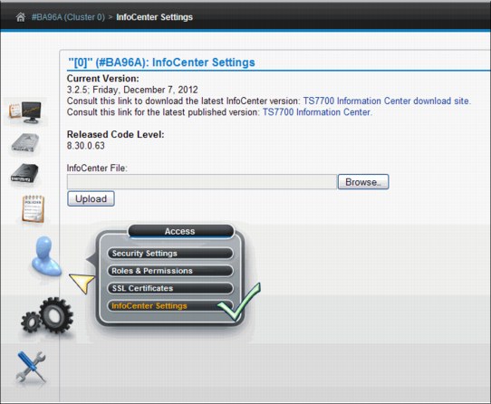
Figure 9-95 InfoCenter Settings window
This window has the following items:
•Current Version section, where you can identify or access the following items:
– Identify the version level and date of the information center installed on the cluster.
– Access a product database where you can download a JAR file containing a newer version of the information center.
– Access an external site displaying the most recently published version of the information center.
•The TS7700 Information Center download site link.
Click this link to open the Fix Central product database so that you can download a new version of the TS7700 Virtualization Engine Information Center as a .jar file (if available):
a. Select System Storage from the Product Group menu.
b. Select Tape Systems from the Product Family menu.
c. Select TS7700 Virtualization Engine from the Product menu.
d. Click Continue.
e. On the Select Fixes page, check the box next to the desired InfoCenter Update file (if available).
f. Click Continue.
g. On the Download Options page, select Download using Download Director.
h. Select the check box next to Include prerequisites and co-requisite fixes.
i. Click Continue.
j. On the Download files using Download Director page, ensure that the check box next to the InfoCenter Update version that you want is checked and click Download now. The Download Director applet opens. The downloaded file is saved at C:DownloadDirector.
•After you receive a new .jar file containing the updated information center (either from the Fix Central database or from an SSR), save the .jar file to a local directory.
To upload and install the new information center, perform the following steps:
a. Click Browse to open the File Upload window.
b. Navigate to the folder containing the new .jar file.
c. Highlight the new .jar file name and click Open.
d. Click Upload to install the new information center on the cluster’s MI.
9.2.9 The Settings icon
The TS7700 Virtualization Engine MI pages collected under the Settings icon can help you view or change cluster network settings, feature licenses, and settings for SNMP and library port access groups.
Cluster network settings
Use this page to set or modify IP addresses for the selected IBM Virtualization Engine TS7700 Cluster.
Figure 9-96 on page 554 shows the Cluster Network Setting navigation and the Customer
IP Addresses tab.
IP Addresses tab.

Figure 9-96 Customer IP Addresses tab
Customer IP Addresses tab
Use this tab to set or modify the MI IP addresses for the selected cluster. Each cluster is associated with two routers or switches. Each router or switch is assigned an IP address and one virtual IP address is shared between routers or switches.
|
Note: Any modifications to IP addresses on the accessing cluster interrupt access to that cluster for all current users. If the accessing cluster IP addresses are modified, the current users are redirected to the new virtual address.
|
The following fields show on this tab:
•IPv4: Select this radio button if the cluster can be accessed by an IPv4 address. If this option is disabled, all incoming IPv4 traffic is blocked, although loop-back traffic is still permitted.
If this option is enabled, you must specify the following addresses:
– <Cluster Name> IP address: An AIX virtual IPv4 address that receives traffic on both customer networks. This field cannot be blank if IPv4 is enabled.
– Primary Address: The IPv4 address for the primary customer network. This field cannot be blank if IPv4 is enabled.
– Secondary Address: The IPv4 address for the secondary customer network. This field cannot be blank if IPv4 is enabled.
– Subnet Mask: The IPv4 subnet mask used to determine the addresses present on the local network. This field cannot be blank if IPv4 is enabled.
– Gateway: The IPv4 address used to access machines outside the local network.
A valid IPv4 address is 32 bits long, consists of four decimal numbers, each ranging from 0 to 255, separated by periods, such as 98.104.120.12
•IPv6: Select this radio button if the cluster can be accessed by an IPv6 address. If this option is disabled, all incoming IPv6 traffic is blocked, although loop-back traffic is still permitted. If you enable this option and do not designate any additional IPv6 information, the minimum required local addresses for each customer network interface will automatically be enabled and configured using neighbor discovery.
If this option is enabled, you can specify the following addresses:
– Primary Address: The IPv6 address for the primary network. This field cannot be blank if IPv6 is enabled.
– Secondary Address: The IPv6 address for the secondary network. This field cannot be blank if IPv6 is enabled.
– Prefix Length: The IPv6 prefix length used to determine the addresses present on the local network. The value in this field is an integer between 1 - 128. This field cannot be blank if IPv6 is enabled.
– Gateway: The IPv6 address used to access machines outside the local network.
A valid IPv6 address is a 128-bit long hexadecimal value separated into 16-bit fields by colons, such as 3afa:1910:2535:3:110:e8ef:ef41:91cf
Leading zeros can be omitted in each field, so that :0003: can be written as :3:. A double colon (::) can be used once per address to replace multiple fields of zeros, for example,
3afa:0:0:0:200:2535:e8ef:91cf
can be written as:
3afa::200:2535:e8ef:91cf
•DNS Server: The IP addresses of any domain name server (DNS), separated by commas. DNS addresses are only needed if you specify a symbolic domain name instead of a numeric IP address for one or more of the following types of information:
– Primary Server URL on the Add External policy page
– Encryption Key Server address
– SNMP server address
– Security server address
If this field is left blank, the DNS server address will be populated by Dynamic Host Configuration Protocol (DHCP).
The address values can be in IPv4 or IPv6 format. A maximum of three DNS servers can be added. Any spaces entered in this field are removed.
To submit changes, click Submit. If your changes apply to the accessing cluster, a warning message is displayed that indicates that the current user access will be interrupted. To accept changes to the accessing cluster, click OK. To reject changes to the accessing cluster and return to the IP Addresses tab, click Cancel.
To reject the changes made to the IP addresses fields and reinstate the last submitted values, select Reset. You can also refresh the page to reinstate the last submitted values for each field.
Encrypt Grid Communication tab
Use this tab to encrypt grid communication between specific clusters.
|
Important: Enabling grid encryption significantly affects the performance of the TS7700 Virtualization Engine. System performance can be reduced by 70% or more when grid encryption is enabled.
|
Figure 9-97 shows the Encrypt Grid Communication tab. In the example, the option was to encrypt grid communications between Cluster 3 and Cluster 5, and also between Cluster 0 and Cluster 3. The remaining paths will not be encrypted in the example.
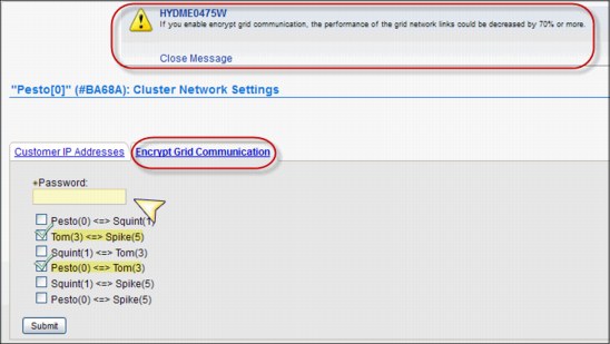
Figure 9-97 Encrypt Grid Communication tab
This tab includes the following fields:
•Password: This password is used as an encryption key to protect grid communication. This value has a 255 ASCII character limit and is required.
•Cluster communication paths: Check the box next to each cluster communication path to be encrypted.
You can only select a communication path between two clusters if both clusters meet all the following conditions:
•Are online
•Operate at a microcode level of 8.30.0.x or higher
•Operate using IPv6-capable servers (3957-V07/VEB)
To submit changes, click Submit.
Feature licenses
Use this page to view information about feature licenses, or to activate or remove feature licenses from the IBM Virtualization Engine TS7700 Cluster.
Check Figure 9-98 on page 557 to see the Feature Licenses page.

Figure 9-98 Feature Licenses page
The fields on the Feature Licenses page in the MI are described:
Cluster common resources
The Cluster common resources table displays a summary of resources affected by activated features. The following information is displayed:
The Cluster common resources table displays a summary of resources affected by activated features. The following information is displayed:
Cluster-Wide Disk Cache Enabled
The amount of disk cache enabled for the entire cluster, in terabytes (TB). If the selected cluster does not possess a physical library, the value in this field displays the total amount of cache installed on the cluster. Access to cache by a cluster without a physical library is not controlled by feature codes.
The amount of disk cache enabled for the entire cluster, in terabytes (TB). If the selected cluster does not possess a physical library, the value in this field displays the total amount of cache installed on the cluster. Access to cache by a cluster without a physical library is not controlled by feature codes.
Cross-Cluster Communication (Grid)
Whether cross-cluster communication is enabled on the grid. If this option is enabled, multiple clusters can form a grid. The possible values are Enabled and Disabled.
Whether cross-cluster communication is enabled on the grid. If this option is enabled, multiple clusters can form a grid. The possible values are Enabled and Disabled.
Peak data throughput
The Peak data throughput table displays for each vNode the peak data throughput in megabytes per second (MB/s). The following information is displayed:
The Peak data throughput table displays for each vNode the peak data throughput in megabytes per second (MB/s). The following information is displayed:
vNode Name of the vNode.
Peak data throughput
The upper limit of the data transfer speed between the vNode and the host, displayed in MB/s.
The upper limit of the data transfer speed between the vNode and the host, displayed in MB/s.
Currently activated feature licenses
The Currently activated feature licenses table displays a summary of features installed on each cluster:
The Currently activated feature licenses table displays a summary of features installed on each cluster:
Feature Code The feature code number of the installed feature.
Feature Description A description of the feature installed by the feature license.
License Key The 32-character license key for the feature.
Node The name and type of the node on which the feature is installed.
Node Serial Number The serial number of the node on which the feature is installed.
Activated The date and time the feature license was activated.
Expires The expiration status of the feature license. The following values are possible:
Day/Date The day and date on which the feature license is set to expire.
Never The feature is permanently active and never expires.
One-time use The feature can be used once and has not yet been used.
|
Note: You can back up these settings as part of the ts7700_cluster<cluster ID>.xmi file and restore them for later use. When the backup settings are restored, new settings are added but no settings are deleted. You cannot restore feature license settings to a cluster different than the cluster that created the ts7700_cluster<cluster ID>.xmi backup file. After you restore feature license settings on a cluster, it is suggested that you log out and then log in to refresh the system.
|
Use the drop-down menu on the Currently activated feature licenses table to activate or remove a feature license. You can also use this drop-down menu to sort and filter feature license details.
SNMP
Use this page on the TS7700 Virtualization Engine MI to view or modify the simple network management protocols (SNMP) configured on an IBM Virtualization Engine TS7700 Cluster. Figure 9-99 on page 558 shows the SNMP page in the MI.
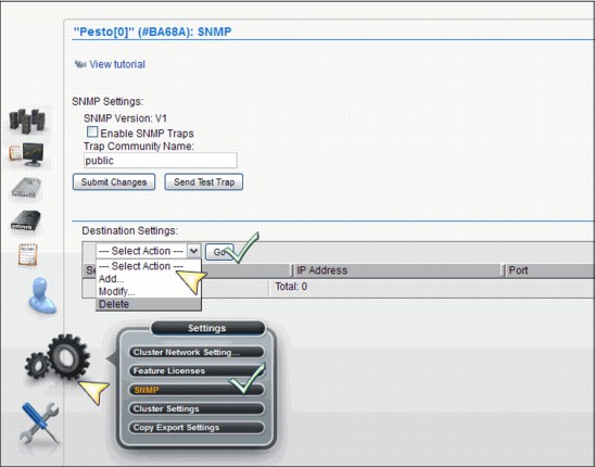
Figure 9-99 SNMP page and options
This page enables you to configure SNMP traps that will log events, such as logins, configuration changes, status changes (vary on, vary off, or service prep), shutdown, and code updates. SNMP is a networking protocol that allows an IBM Virtualization Engine TS7700 to automatically gather and transmit information about alerts and status to other entities in the network.
When adding or modifying SNMP destinations, it is strongly suggested that you use this advice:
•Use IPv4 or IPv6 addresses as destinations rather than a fully qualified domain name (FQDN)
•Verify that any FQDN used correctly addresses its IP address
Test only one destination at a time when testing SNMP configuration to ensure that FQDN destinations are working properly.
SNMP settings
Use this section to configure global settings that apply to SNMP traps on an entire cluster. The following settings are configurable:
SNMP Version The SNMP version. It defines the protocol used in sending SNMP requests and is determined by the tool you are using to monitor SNMP traps. Different versions of SNMP traps work with different management applications. The following values are possible:
V1 The suggested trap version; compatible with the greatest number of management applications. No alternate version is supported.
Enable SNMP Traps A check box that enables or disables SNMP traps on a cluster. A checked box enables SNMP traps on the cluster; a cleared box disables SNMP traps on the cluster. The check box is cleared, by default.
Trap Community Name
The name that identifies the trap community and is sent along with the trap to the management application. This value behaves as a password; the management application will not process an SNMP trap unless it is associated with the correct community. This value must be 1 - 15 characters in length and composed of Unicode characters. The default value for this field is “public”.
The name that identifies the trap community and is sent along with the trap to the management application. This value behaves as a password; the management application will not process an SNMP trap unless it is associated with the correct community. This value must be 1 - 15 characters in length and composed of Unicode characters. The default value for this field is “public”.
Send Test Trap Select this button to send a test SNMP trap to all destinations listed in the Destination Settings table using the current SNMP trap values. The Enable SNMP Traps check box does not need to be checked to send a test trap.
If the SNMP test trap is received successfully and the information is correct, select the Submit Changes button.
Submit Changes Select this button to submit changes to any of the global settings, including the fields SNMP Version, Enable SNMP Traps, and Trap Community Name.
Destination Settings Use the Destination Settings table to add, modify, or delete a destination for SNMP trap logs. You can add, modify, or delete a maximum of 16 destination settings at one time.
|
Note: A user with read-only permissions cannot modify the contents of the Destination Settings table.
|
The following settings are configurable:
IP Address The IP address of the SNMP server. This value can take any of the following formats: IPv4, IPv6, a hostname resolved by the machine (such as localhost), or an FQDN if a domain name server (DNS) is provided. A value in this field is required.
|
Tip: A valid IPv4 address is 32 bits long, consists of four decimal numbers, each ranging from 0 - 255, separated by periods, such as 98.104.120.12
A valid IPv6 address is a 128-bit long hexadecimal value separated into 16-bit fields by colons, such as 3afa:1910:2535:3:110:e8ef:ef41:91cf. Leading zeros can be omitted in each field, so that :0003: can be written as :3:. A double colon (::) can be used once per address to replace multiple fields of zeros.
For example, “3afa:0:0:0:200:2535:e8ef:91cf” is also “3afa::200:2535:e8ef:91cf”.
|
Port The port to which the SNMP trap logs are sent. This value must be a number between 0 - 65535. A value in this field is required.
Use the Select Action drop-down menu on the Destination Settings table to add, modify, or delete an SNMP trap destination. Destinations are changed in the vital product data (VPD) as soon as they are added, modified, or deleted. These updates do not depend on the selection of the Submit Changes button.
|
Note: Any change to SNMP settings is logged on the Tasks page.
|
Library Port Access Groups page
Use this page to view information about library port access groups used by the IBM Virtualization Engine TS7700. Library port access groups enable you to segment resources and authorization by controlling access to library data ports. Figure 9-100 shows the library port access group link.
|
Tip: This page is only visible if at least one instance of FC5271 (Selective device access control (SDAC)) is installed on all clusters in the grid.
|
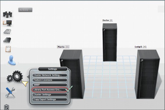
Figure 9-100 Library Port Access Group link
Access Groups table
The Access Groups table displays information about existing library port access groups. Figure 9-101 on page 561 shows the Library Port Access Groups page.
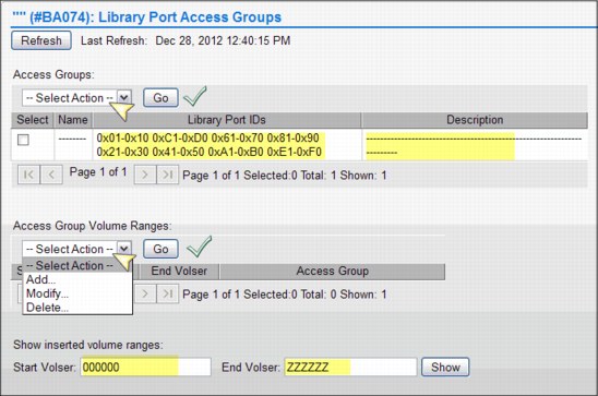
Figure 9-101 Library Port Access Groups page
You can use the Access Groups table to create a new library port access group. Also, you can modify or delete an existing access group as shown in Figure 9-102 on page 562.
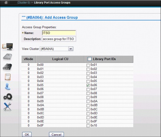
Figure 9-102 Add Access group
The following status information is displayed in the Access Groups table:
Name The identifying name of the access group. This name must be unique and cannot be modified after it is created. It must contain between one and eight characters and the first character in this field cannot be a number. Valid characters for this field are A - Z, 0 - 9, $, @, *, #, and %.
The default access group is identified by the name "- - - - - - - - ". This group can be modified but cannot be deleted.
Library Port IDs A list of Library Port IDs accessible using the defined access group. This field contains a maximum of 750 characters, or 31 Library Port IDs separated by commas or spaces. A range of Library Port IDs is signified by using a hyphen (-). This field can be left blank.
The default access group has a value in this field that is 0x01-0xFF. Initially, all port IDs are shown by default: however after modification, this field can change to show only the IDs corresponding to the existing vNodes.
|
Important: VOLSERs not found in the Selective Device Access Control (SDAC) VOLSER range table use this default group to determine access. You can modify this group to remove any or all default Library Port IDs. However, if all default Library Port ID values are removed, no access is granted to any volumes not in a defined range.
|
Description A description of the access group. This field contains a maximum of 70 characters.
Use the Select Action drop-down menu on the Access Groups table to add, modify, or delete a library port access group.
Access Groups Volume Ranges
The Access Groups Volume Ranges table displays VOLSER range information for existing library port access groups. You can also use the Select Action drop-down menu on this table to add, modify, or delete a VOLSER range defined by a library port access group.
The Access Groups Volume Ranges table displays VOLSER range information for existing library port access groups. You can also use the Select Action drop-down menu on this table to add, modify, or delete a VOLSER range defined by a library port access group.
Start VOLSER The first VOLSER in the range defined by a given access group.
End VOLSER The last VOLSER in the range defined by a given access group.
Access Group The identifying name of the access group, defined by the Name field in the Access Groups table.
Use the Select Action drop-down menu on the Access Group Volume Ranges table to add, modify, or delete a VOLSER range associated with a given library port access group.
You can show the inserted volume ranges. To view the current list of virtual volume ranges in the TS7700 Cluster, enter the start and end VOLSERs and click Show.
|
Note: Access groups and access group ranges are backed up and restored together. For additional information, see “Backup settings” on page 572 and “Restore Settings page” on page 575.
|
Cluster settings
Cluster settings can help you view or change settings that determine how a cluster performs copy policy overrides, applies Inhibit Reclaim schedules, uses an encryption key server, implements write protect mode, and performs backup and restore operations.
See Chapter 2, “Architecture, components, and functional characteristics” on page 15 for an evaluation of different scenarios and examples where those overrides benefit the overall performance.
Copy Policy Override
Figure 9-103 on page 564 shows the Cluster Settings panel navigating to the Copy Policy Override page.
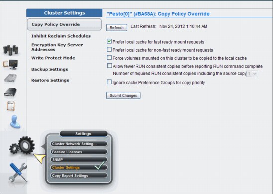
Figure 9-103 Cluster Settings and Copy Policy Override
Use this page to override local copy and I/O policies for a given IBM Virtualization Engine TS7700 Cluster. For the selected cluster, you can tailor copy policies to override certain copy or I/O operations. Select the check box next to one or more of the following settings to specify a policy override:
•Prefer local cache for Fast Ready mount requests
When this setting is selected, a scratch (Fast Ready) mount selects the local TVC in the following conditions:
– The Copy Mode field defined by the Management Class for the mount has a value other than No Copy defined for the local cluster.
– The local cluster is not in a degraded state. The following examples are degraded states:
• Out of cache resources
• Out of physical scratch
|
Note: This override can be enabled independently of the current status of the copies in the cluster.
|
•Prefer local cache for non-Fast Ready mount requests
This override causes the local cluster to satisfy the mount request if both of the following conditions are true:
– The cluster is available.
– The local cluster has a valid copy of the data, even if that data is only resident on physical tape.
If the local cluster does not have a valid copy of the data, the default cluster selection criteria applies.
•Force volumes mounted on this cluster to be copied to the local cache
When this setting is selected for a private (non-Fast Ready) mount, a copy operation is performed on the local cluster as part of the mount processing. When this setting is selected for a scratch (Fast Ready) mount, the Copy Consistency Point on the specified Management Class is overridden for the cluster with a value of Rewind Unload. This override does not change the definition of the Management Class, but influences the replication policy.
•Allow fewer RUN consistent copies before reporting RUN command complete
When this setting is selected, the maximum number of Rewind Unload (RUN) copies, including the source, is determined by the value entered at Number of required RUN consistent copies including the source copy. This value must be consistent before the RUN operation completes. If this option is not selected, the Management Class definitions are used explicitly. Therefore, the number of RUN copies can be from one to the number of clusters in the grid configuration or the total number of clusters configured with a RUN Copy Consistency Point.
•Ignore cache preference groups for copy priority
If this option is selected, copy operations ignore the cache preference group when determining the priority of volumes copied to other clusters.
|
Note: These settings override the default TS7700 Virtualization Engine behavior and can be different for every cluster in a grid.
|
Follow these steps to change any of the settings on this page:
1. Check or clear the box next to the setting that you want to change. If you enable “Allow fewer RUN consistent copies before reporting RUN command complete”, you can alter the value for Number of required RUN consistent copies including the source copy.
2. Click Submit Changes.
Inhibit Reclaim Schedules page
Use this page to add, modify, or delete Inhibit Reclaim schedules used to postpone tape reclamation in an IBM Virtualization Engine TS7700 cluster.
This page is visible but disabled on the TS7700 Virtualization Engine MI if the grid possesses a physical library, but the selected cluster does not. The following message is displayed:
The cluster is not attached to a physical tape library.
|
Tip: This page is not visible on the TS7700 Virtualization Engine MI if the grid does not possess a physical library.
|
Reclamation can improve tape utilization by consolidating data on some physical volumes, but it consumes system resources and can affect host access performance. The Inhibit Reclaim schedules function can be used to disable reclamation in anticipation of increased host access to physical volumes. Figure 9-104 on page 566 shows an Inhibit Reclamation Schedules panel.
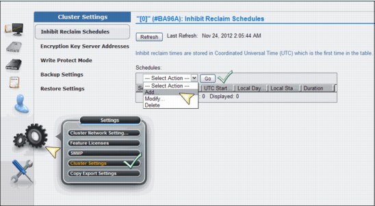
Figure 9-104 Inhibit Reclaim Schedules panel
The following fields on this page are described:
Schedules The Schedules table displays the list of Inhibit Reclaim schedules defined for each partition of the grid. It displays the day, time, and duration of any scheduled reclamation interruption. All inhibit reclaim dates and times are displayed first in Coordinated Universal Time (UTC) and then in local time. The status information is displayed in the Schedules table:
UTC Day of Week The UTC day of the week on which the reclamation will be inhibited. The following values are possible:
Every Day Sunday, Monday, Tuesday, Wednesday, Thursday, Friday, or Saturday
UTC Start Time The UTC time in hours (H) and minutes (M) at which reclamation will begin to be inhibited. The values in this field must take the form HH:MM. Possible values for this field include 00:00 through 23:59.
The Start Time field is accompanied by a time chooser clock icon. You can enter hours and minutes manually by using 24-hour time designations, or you can use the time chooser to select a start time based on a 12-hour (AM/PM) clock.
Local Day of Week The day of the week in local time on which the reclamation will be inhibited. The day recorded reflects the time zone in which your browser is located. The following values are possible:
Every Day Sunday, Monday, Tuesday, Wednesday, Thursday, Friday, or Saturday
Local Start Time The local time in hours (H) and minutes (M) at which reclamation will begin to be inhibited. The values in this field must take the form HH:MM. The time recorded reflects the time zone in which your browser is located. Possible values for this field include 00:00 through 23:59. The Start Time field is accompanied by a time chooser clock icon. You can enter hours and minutes manually using 24-hour time designations, or you can use the time chooser to select a start time based on a 12-hour (AM/PM) clock.
Duration The number of days (D) hours (H) and minutes (M) that the reclamation will be inhibited. The values in this field must take the form: DD days HH hours MM minutes. Possible values for this field include 0 day 0 hour 1 minute through 1 day 0 hour 0 minute if the day of the week is Every Day. Otherwise, possible values for this field are 0 day 0 hour 1 minute through 7 days 0 hour 0 minute.
|
Note: Inhibit Reclaim schedules cannot overlap.
|
Use the drop-down menu on the Schedules table to add a new Inhibit Reclaim schedule or to modify or delete an existing schedule. Figure 9-105 shows the Add Inhibit Reclaim Schedule page.
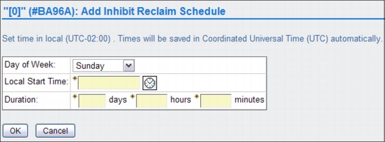
Figure 9-105 Add Inhibit Reclaim Schedule panel
To modify an Inhibit Reclaim schedule, follow these steps:
a. From the Inhibit Reclaim Schedules page, navigate to the Schedules table.
b. Select the radio button next to the Inhibit Reclaim schedule to be modified.
c. Select Modify from the Select Action drop-down menu.
d. Click Go to open the Modify Inhibit Reclaim Schedule page.
The values are the same as for the Add Inhibit Reclaim Schedule, listed in Figure 9-105.
To delete an Inhibit Reclaim schedule, follow these steps:
a. From the Inhibit Reclaim Schedules page, navigate to the Schedules table.
b. Select the radio button next to the Inhibit Reclaim schedule you want to delete.
c. Select Delete from the Select Action drop-down menu.
d. Click Go to open the Confirm Delete Inhibit Reclaim Schedule page.
Click OK to delete the Inhibit Reclaim schedule and return to the Inhibit Reclaim Schedules page, or click Cancel to abandon the delete operation and return to the Inhibit Reclaim Schedules page.
|
Note: Plan the Inhibit Reclaim schedules carefully. Running the reclaims during peak times can affect your production, and not having enough reclaim schedules will influence your media consumption.
|
Encryption Key Server Addresses page
Use this page for setting the Encryption Key Server addresses in the IBM Virtualization Engine TS7700.
To watch a tutorial showing the properties of the encryption key server, click the View tutorial link in the MI page. Figure 9-106 shows the Encryption Key Server Addresses setup page.

Figure 9-106 Encryption Key Server Addresses page
This page is visible but disabled on the TS7700 Virtualization Engine MI if the grid possesses a physical library, but the selected cluster does not. The following message is displayed:
The cluster is not attached to a physical tape library.
|
Tip: This page is not visible on the TS7700 Virtualization Engine MI if the grid does not possess a physical library.
|
The Encryption Key Server assists encryption-enabled tape drives in generating, protecting, storing, and maintaining encryption keys that are used to encrypt information being written to and to decrypt information being read from tape media (tape and cartridge formats).
|
Note: Your Encryption Key Server software must support default keys to use this option.
|
The following settings are used to configure the IBM Virtualization Engine TS7700 connection to an encryption key server.
|
Note: You can back up these settings as part of the ts7700_cluster<cluster ID>.xmi file and restore them for later use or use with another cluster. If a key server address is empty at the time that the backup is performed, when it is restored, the port settings are the same as the default values.
|
The settings are described:
•Primary key server address
The key server name or IP address that is primarily used to access the encryption key server. This address can be a fully qualified host name or an IP address in IPv4 or IPv6 format. This field is not required if you do not want to connect to an encryption key server.
|
Tip: A valid IPv4 address is 32 bits long, consists of four decimal numbers, each ranging from 0 - 255, separated by periods, such as 98.104.120.12.
A valid IPv6 address is a 128-bit long hexadecimal value separated into 16-bit fields by colons, such as 3afa:1910:2535:3:110:e8ef:ef41:91cf. Leading zeros can be omitted in each field, so that :0003: can be written as :3:. A double colon (::) can be used once per address to replace multiple fields of zeros. For example, 3afa:0:0:0:200:2535:e8ef:91cf can be written as: 3afa::200:2535:e8ef:91cf.
|
A fully qualified host name is a domain name that uniquely and absolutely names a computer. It consists of the host name and the domain name. The domain name is one or more domain labels that place the computer in the DNS naming hierarchy. The host name and the domain name labels are separated by periods and the total length of the hostname cannot exceed 255 characters.
•Primary key server port
The port number of the primary key server. Valid values are any whole number between 0 and 65535; the default value is 3801. This field is only required if a primary key address is used.
•Secondary key server address
The key server name or IP address that is used to access the Encryption Key Server when the primary key server is unavailable. This address can be a fully qualified host name or an IP address in IPv4 or IPv6 format. This field is not required if you do not want to connect to an encryption key server. See the primary key server address description for IPv4, IPv6, and fully qualified host name value parameters.
•Secondary key server port
The port number of the secondary key server. Valid values are any whole number between 0 and 65535; the default value is 3801. This field is only required if a secondary key address is used.
•Using the Ping Test
Use the Ping Test buttons to check the cluster network connection to a key server after changing a cluster’s address or port. If you change a key server address or port and do not submit the change before using the Ping Test button, you will receive the following message:
In order to perform a ping test you must first submit your address and/or port changes.
Once the ping test has been issued, one of the following two messages will occur:
– T he ping test against the address “<address>” on port “<port>” was successful.
– The ping test against the address “<address>” on port “<port>” from “<cluster>” has failed. The error returned was: <error text>.
Click Submit Changes to save changes to any of these settings.
Write Protect Mode page
Use this page to view Write Protect Mode settings in an IBM Virtualization Engine TS7700 Cluster.
When Write Protect Mode is enabled on a cluster, host commands fail if they are issued to virtual devices in that cluster and attempt to modify a volume’s data or attributes. Meanwhile, host commands issued to virtual devices in peer clusters are allowed to continue with full read and write access to all volumes in the library. Write Protect Mode is used primarily for client-initiated disaster recovery testing. In this scenario, a recovery host connected to a non-production cluster must access and validate production data without any risk of modifying it.
A cluster can be placed into Write Protect Mode only if the cluster is online. After the mode is set, the mode is retained through intentional and unintentional outages and can only be disabled through the same MI panel used to enable the function. When a cluster within a grid configuration has Write Protect Mode enabled, standard grid functions, such as virtual volume replication and virtual volume ownership transfer, are unaffected.
Virtual volume categories can be excluded from Write Protect Mode. Up to 16 categories can be identified and set to include or exclude from Write Protect Mode using the Category Write Protect Properties table. Additionally, write-protected volumes in any scratch (Fast Ready) category can be mounted as private volumes if the “Ignore Fast Ready characteristics of write-protected categories” check box is selected. Figure 9-107 shows the Write Protect Mode page.

Figure 9-107 Write Protect Mode page
Current State The current status of Write Protect Mode on the active cluster. The following values are possible:
Disabled Write Protect Mode is disabled on the cluster. No Write Protect settings are in effect for the cluster.
Enabled Write Protect Mode is enabled on the cluster. Any attempt by an attached host to modify a volume or its attributes fails, subject to any defined category exclusions.
Disable Write Protect Mode
Select this radio button to disable Write Protect Mode on the active cluster. If you select this option, no volumes on the cluster are write-protected; all Write Protect settings are disabled.
Select this radio button to disable Write Protect Mode on the active cluster. If you select this option, no volumes on the cluster are write-protected; all Write Protect settings are disabled.
Enable Write Protect Mode
Select this radio button to enable Write Protect Mode on the active cluster. This option prevents hosts attached to this cluster from modifying volumes or their attributes.
Select this radio button to enable Write Protect Mode on the active cluster. This option prevents hosts attached to this cluster from modifying volumes or their attributes.
Ignore Fast Ready characteristics of write protected categories
If this check box is selected, write-protected volumes that have been returned to a scratch or a Fast Ready category will continue to be viewed as private volumes. This allows a disaster recovery test host to mount production volumes as private volumes even though the production environment has since returned them to scratch. Peer clusters, such as production clusters, will continue to view these volumes as scratch volumes. This setting will not override the scratch (Fast Ready) characteristics of the excluded categories.
If this check box is selected, write-protected volumes that have been returned to a scratch or a Fast Ready category will continue to be viewed as private volumes. This allows a disaster recovery test host to mount production volumes as private volumes even though the production environment has since returned them to scratch. Peer clusters, such as production clusters, will continue to view these volumes as scratch volumes. This setting will not override the scratch (Fast Ready) characteristics of the excluded categories.
Category Write Protect Properties
Use the Category Write Protect Properties table to add, modify, or delete categories to be selectively excluded from Write Protect Mode. Disaster recovery test hosts or locally connected production partitions can continue to read and write to local volumes as long as their volume categories are excluded from write protect. These hosts must utilize a set of categories different than those primary production categories that are write protected.
Use the Category Write Protect Properties table to add, modify, or delete categories to be selectively excluded from Write Protect Mode. Disaster recovery test hosts or locally connected production partitions can continue to read and write to local volumes as long as their volume categories are excluded from write protect. These hosts must utilize a set of categories different than those primary production categories that are write protected.
When Write Protect Mode is enabled, any categories added to this table must display a value of Yes in the Excluded from Write Protect field before the volumes in that category can be modified by an accessing host. Figure 9-108 on page 572 shows the Add Category panel.

Figure 9-108 Add Category panel
The following category fields are displayed in the Category Write Protect Properties table:
•Category Number: The identifier for a defined category. This is an alphanumeric hexadecimal value between 0x0001 and 0xFEFF (0x0000 and 0xFFxx cannot be used). Values entered do not include the 0x prefix, although this prefix is displayed on the Cluster Summary page. Values entered are padded up to four places. Letters used in the category value must be capitalized.
•Excluded from Write Protect: Whether the category is excluded from Write Protect Mode. The following values are possible:
– Yes: The category is excluded from Write Protect Mode. When Write Protect is enabled, volumes in this category can be modified when accessed by a host.
– No: The category is not excluded from Write Protect Mode. When Write Protect is enabled, volumes in this category cannot be modified when accessed by a host.
•Description: A descriptive definition of the category and its purpose. This description must contain between 0- 63 Unicode characters.
Use the drop-down menu on the Category Write Protect Properties table to add a new category or modify or delete an existing category.
|
Note: You can add up to 16 categories per cluster; however, you cannot add, modify, or delete categories if one or more clusters in the grid are operating at a code level of 8.6.0.xx or lower.
|
You must click Submit Changes to save any changes made to the Write Protect Mode settings.
Backup settings
Use this page to back up the settings from an IBM Virtualization Engine TS7700 Cluster. Figure 9-109 on page 573 presents a Backup Settings page.

Figure 9-109 Backup Settings page
|
Important: Backup and restore functions are not supported between clusters operating at different code levels. Only clusters operating at the same code level as the accessing cluster (the one addressed by the web browser) can be selected for Backup or Restore. Clusters operating different code levels are visible, but options are greyed out.
|
The Backup Settings table lists the cluster settings that are available for backup:
•Categories: Select this check box to back up scratch (Fast Ready) categories used to group virtual volumes.
•Physical Volume Pools: Select this check box to back up physical volume pool definitions.
|
Note: If the cluster does not possess a physical library, physical volume pools will not be available.
|
•All Constructs: Select this check box to select all of the following constructs for backup. Alternatively, you can select a specific construct by checking the box for the one you want:
– Storage Groups: Select this check box to back up defined Storage Groups.
– Management Classes: Select this check box to back up defined Management Classes.
– Storage Classes: Select this check box to back up defined storage classes.
– Data Classes: Select this check box to back up defined Data Classes.
•Inhibit Reclaim Schedule: Select this check box to back up the Inhibit Reclaim schedules used to postpone tape reclamation.
|
Note: If the cluster does not possess a physical library, the Inhibit Reclaim Schedules option will not be available.
|
•Library Port Access Groups: Select this check box to back up defined library port access groups.
|
Note: This setting is only available if all clusters in the grid are operating with microcode levels of 8.20.0.xx or higher and the SDAC feature is installed.
|
Library port access groups and access group ranges are backed up and restored together.
•Physical Volume Ranges: Select this check box to back up defined physical volume ranges. If the cluster does not possess a physical library, physical volume ranges will not be available.
•Security Settings: Select this check box to back up defined security settings, for example:
– Session Timeout
– Account Expiration
– Account Lock
– Encryption Key Server Addresses
– Primary key server address
– Primary key server port
– Secondary key server address
– Secondary key server port
•Cluster Network Settings
•Roles & Permissions: Select this check box to back up defined custom user roles.
|
Important: A restore operation following a backup of cluster settings does not restore or otherwise modify any user, role, or password settings defined by a security policy.
|
•Feature Licenses: Select this check box to back up the settings for currently activated feature licenses.
|
Note: You can back up these settings as part of the ts7700_cluster<cluster ID>.xmi file and restore them for later use on the same cluster. However, you cannot restore feature license settings to a cluster different than the cluster that created the ts7700_cluster<cluster ID>.xmi backup file.
|
The following feature license information is available for backup:
Feature Code The feature code number of the installed feature.
Feature Description A description of the feature installed by the feature license.
License Key The 32-character license key for the feature.
Node The name and type of the node on which the feature is installed.
Node Serial Number The serial number of the node on which the feature is installed.
Activated The date and time the feature license was activated.
Expires The expiration status of the feature license. The following values are possible:
Day/Date The day and date on which the feature license is set to expire.
Never The feature is permanently active and never expires.
One-time use The feature can be used once and has not yet been used.
Cluster Network Settings
Select this check box to back up the defined cluster network settings.
Select this check box to back up the defined cluster network settings.
Roles & Permissions
Select this check box to back up defined custom user roles.
Select this check box to back up defined custom user roles.
Encryption Key Server Addresses
Select this check box to back up defined Encryption Key Server addresses:
Select this check box to back up defined Encryption Key Server addresses:
• Primary key server address
• Primary key server port
• Secondary key server address
• Secondary key server port
|
Important: A restore operation following a backup of cluster settings does not restore or otherwise modify any user, role, or password settings defined by a security policy.
|
To back up cluster settings, click a check box adjacent to any of the previous settings and then click Download. A window opens to show that the backup is in progress.
|
Important: If you navigate away from this page while the backup is in progress, the backup operation is stopped and the operation must be restarted.
|
When the backup operation is complete, the backup file ts7700_cluster<cluster ID>.xmi is created. This file is an XML Meta Interchange file. You are prompted to open the backup file or save it to a directory. Save the file.
When prompted to open or save the file to a directory, it is suggested that you save the file without changing the .xmi file extension or the file contents. Any changes to the file contents or extension can cause the restore operation to fail. You can modify the file name before saving it if you want to retain this backup file following subsequent backup operations. If you choose to open the file, it is suggested that you not use Microsoft Excel to view or save it. Microsoft Excel changes the encoding of an XML Meta Interchange file, and the changed file is corrupted when used during a restore operation.
The following settings are not available for backup or recovery:
•User accounts
•Grid identification policies
•Cluster identification policies
•Write protect mode
•LDAP external authentication policies
You must record these settings in a safe place and recover them manually.
Restore Settings page
Use this page to restore the settings from an IBM Virtualization Engine TS7700 Cluster to a recovered or new cluster.
|
Note: Backup and restore functions are not supported between clusters operating at different code levels. Only clusters operating at the same code level as the current cluster can be selected from the Current Cluster Selected graphic. Clusters operating at different code levels are visible, but grayed out, in the graphic.
|
Figure 9-110 shows the Restore Settings panel.

Figure 9-110 Restore Settings Panel
Follow these steps to restore cluster settings. On the Restore Settings page, click Browse to open the File Upload window. Navigate to the backup file used to restore the cluster settings. This file has an .xmi extension. Add the file name to the File name field. Click Open or press Enter from your keyboard.
Click Show file to review the cluster settings contained in the backup file. The backup file can contain any of the following settings, but only those settings defined by the backup file will be shown:
•Categories : Select this check box to restore scratch (Fast Ready) categories used to group virtual volumes.
•Physical Volume Pools: Select this check box to restore physical volume pool definitions.
|
Note: If the backup file was created by a cluster that did not possess a physical library, physical volume pool settings are reset to default.
|
•All Constructs: Select this check box to restore all of the displayed constructs.
•Storage Groups: Select this check box to restore defined Storage Groups.
•Management Classes: Select this check box to restore defined Management Classes.
|
Important: Management Class settings are related to the number and order of clusters in a grid. Take special care when restoring this setting. If a Management Class is restored to a grid having more clusters than the grid had when the backup was performed, the copy policy for the new cluster or clusters will be set as No Copy. If a Management Class is restored to a grid having fewer clusters than the grid had when the backup was performed, the copy policy for the now-nonexistent clusters will be changed to No Copy. The copy policy for the first cluster will be changed to RUN to ensure that one copy exists in the cluster.
|
If cluster IDs in the grid differ from cluster IDs present in the restore file, Management Class copy policies on the cluster are overwritten with those from the restore file. Management Class copy policies can be modified after the restore operation completes.
|
Note: If the backup file was created by a cluster that did not define one or more scratch mount candidates, the default scratch mount process is restored. The default scratch mount process is a random selection routine that includes all available clusters. Management Class scratch mount settings can be modified after the restore operation completes.
|
•Storage Classes: Select this check box to restore defined storage classes.
•Data Classes: Select this check box to restore defined Data Classes.
|
Note: If this setting is selected and the cluster does not support logical Write Once Read Many (LWORM), the Logical WORM setting is disabled for all Data Classes on the cluster.
|
•Inhibit Reclaim Schedule: Select this check box to restore Inhibit Reclaim schedules used to postpone tape reclamation.
A current Inhibit Reclaim schedule is not overwritten by older settings. An earlier Inhibit Reclaim schedule is not restored if it conflicts with an Inhibit Reclaim schedule that currently exists.
|
Note: If the backup file was created by a cluster that did not possess a physical library, the Inhibit Reclaim schedules settings are reset to default.
|
•Library Port Access Groups: Select this check box to restore defined library port access groups.
|
Note: This setting is only available if all clusters in the grid are operating with microcode levels of 8.20.0.xx or higher.
|
Library port access groups and access group ranges are backed up and restored together.
•Physical Volume Ranges: Select this check box to restore defined physical volume ranges.
|
Note: If the backup file was created by a cluster that did not possess a physical library, physical volume range settings are reset to default.
|
•Roles & Permissions: Select this check box to restore defined custom user roles.
|
Important: A restore operation following a backup of cluster settings does not restore or otherwise modify any user, role, or password settings defined by a security policy.
|
•Security Settings: Select this check box to restore defined security settings, for example:
– Session Timeout
– Account Expiration
– Account Lock
•Encryption Key Server Addresses: Select this check box to restore defined Encryption Key Server addresses. If a key server address is empty at the time that the backup is performed, when restored, the port settings are the same as the default values. The following Encryption Key Server address settings can be restored:
– Primary key server address: The key server name or IP address that is primarily used to access the encryption key server.
– Primary key server port: The port number of the primary key server.
– Secondary key server address: The key server name or IP address that is used to access the Encryption Key Server when the primary key server is unavailable.
– Secondary key server port: The port number of the secondary key server.
•Cluster Network Settings: Select this check box to restore the defined cluster network settings.
|
Important: Changes to network settings affect access to the TS7700 MI. When these settings are restored, routers that access the TS7700 MI are reset. No TS7700 grid communications or jobs are affected, but any current users are required to log back on to the TS7700 MI using the new IP address.
|
•Feature Licenses: Select this check box to restore the settings for currently activated feature licenses. When the backup settings are restored, new settings are added but no settings are deleted. After you restore feature license settings on a cluster, it is suggested that you log out and then log in to refresh the system.
|
Note: You cannot restore feature license settings to a cluster different than the cluster that created the ts7700_cluster<cluster ID>.xmi backup file.
|
The following feature license information is available for backup:
Feature Code The feature code number of the installed feature.
Feature Description A description of the feature installed by the feature license.
License Key The 32-character license key for the feature.
Node The name and type of the node on which the feature is installed.
Node Serial Number The serial number of the node on which the feature is installed.
Activated The date and time the feature license was activated.
Expires The expiration status of the feature license. The following values are possible:
Day/Date The day and date on which the feature license is set to expire.
Never The feature is permanently active and never expires.
One-time use The feature can be used once and has not yet been used.
After selecting Show File, the name of the cluster from which the backup file was created is displayed at the top of the page, along with the date and time that the backup occurred.
Check the box next to each setting to be restored. Click Restore.
|
Note: The restore operation will overwrite existing settings on the cluster.
|
A warning page opens and asks you to confirm your decision to restore settings. Click OK to restore settings or Cancel to cancel the restore operation.
The Confirm Restore Settings page opens.
|
Important: If you navigate away from this page while the restore is in progress, the restore operation is stopped and the operation must be restarted.
|
The restore cluster settings operation can take five minutes or longer. During this step, the MI is communicating the commands to update settings. If you navigate away from this page, the restore settings operation is canceled.
Copy Export Settings page
Use this page to change the maximum number of physical volumes that can be exported by the IBM Virtualization Engine TS7700. Figure 9-111 on page 580 shows the Copy Export Settings panel.

Figure 9-111 Copy Export Settings panel
The Number of physical volumes to export is the maximum number of physical volumes that can be exported. This value is an integer between 1 - 10,000. The default value is 2000. To change the number of physical volumes to export, enter an integer in the described field and click Submit.
|
Note: You can modify this field even if a Copy Export operation is running, but the changed value will not take effect until the next Copy Export operation starts.
|
9.2.10 The Service icon
The following topics present information about performing service operations and troubleshooting problems for the TS7700 Virtualization Engine.
Ownership Takeover Mode window
Use the window shown in Figure 9-112 to enable or disable Ownership Takeover Mode for a failed cluster in a TS7700 Virtualization Engine.

Figure 9-112 MI window to set the Ownership Takeover Mode
For a cluster that is in a failed state, enabling Ownership Takeover Mode allows other clusters in the grid to obtain ownership of logical volumes that are owned by the failed cluster. Normally, ownership is transferred from one cluster to another through communication between the clusters. When a cluster fails or the communication path between clusters fails, the normal means of transferring ownership is not available.
Enabling a read/write or read-only takeover mode must not be done if only the communication path between the clusters has failed. A mode must only be enabled for a cluster that is no longer operational. The integrity of logical volumes in the grid can be compromised if a takeover mode is enabled for a cluster that was not actually in a failed state.
Figure 9-113 shows the Ownership Takeover Mode panel when navigating from the panel that is shown in Figure 9-112 on page 581.

Figure 9-113 Ownership Takeover Mode
If the cluster itself is no longer operational, ownership takeover can be used to access the virtual volumes.
|
Note: Do not attempt ownership takeover if the communication path between clusters has failed but no clusters are in a failed state. The integrity of the virtual volumes in the grid can be compromised if a takeover mode is enabled for a cluster that is not actually in a failed state.
|
Table 9-19 on page 583 compares the read/write and read-only ownership takeover modes.
Table 9-19 Comparing read/write and read-only ownership takeover modes
|
Read/write ownership takeover mode
|
Read-only ownership takeover mode
|
||
|
Operational clusters in the grid can perform these tasks:
•Perform read and write operations on the virtual volumes owned by the failed cluster.
•Change virtual volumes owned by the failed cluster to private or SCRATCH status.
|
Operational clusters in the grid can perform
these tasks: •Perform read operations on the virtual volumes owned by the failed cluster.
Operational clusters in the grid cannot perform these tasks:
•Change the status of a volume to private or scratch.
•Perform read and write operations on the virtual volumes owned by the failed cluster.
|
||
|
A consistent copy of the virtual volume must be available on the grid or the virtual volume must exist in a scratch category. If no cluster failure occurred (grid links down) and the ownership takeover was invoked by mistake, the possibility exists for two sites to write data to the same virtual volume.
|
If no cluster failure occurred, it is possible that a virtual volume accessed by another cluster in read-only takeover mode contains older data than the one on the owning cluster. This situation can occur if the virtual volume was modified on the owning cluster while the communication path between the clusters was down. When the links are reestablished, those volumes will be marked in error.
|
If the Autonomic Ownership Takeover Manager (AOTM) is configured, it performs an additional check to determine whether the unavailable cluster is in a failed state when an ownership takeover is initiated. If AOTM determines that the cluster is not in a failed state, the ownership takeover attempt fails. The following information is displayed in this panel (Figure 9-113 on page 582):
Local Cluster Summary
This section provides a high-level summary of ownership takeover actions performed by the accessing, or local, cluster. The following information is displayed.
This section provides a high-level summary of ownership takeover actions performed by the accessing, or local, cluster. The following information is displayed.
Takeover Enabled Against
A list of the clusters in the grid against which the accessing cluster has enabled ownership takeover. These clusters are in the failed or service state and identified by using this format:
A list of the clusters in the grid against which the accessing cluster has enabled ownership takeover. These clusters are in the failed or service state and identified by using this format:
"Cluster Nickname[Cluster ID]" (#Distributed Library Sequence Number)
Autonomic Ownership Takeover Mode Configuration
This area displays the current AOTM configuration for the accessing cluster. The following information is displayed:
This area displays the current AOTM configuration for the accessing cluster. The following information is displayed:
Remote Cluster The remote, failed cluster that currently owns the virtual volumes to be accessed. The information is displayed in this format: "Cluster Nickname[Cluster ID]"
Takeover Mode The type of ownership applied to the remote cluster. The following values are possible: Read-Only or Read/Write.
See Table 9-19 for a comparison of read-only and read/write ownership takeover modes.
Grace Period (minutes)
The amount of time the accessing cluster waits for a remote cluster to respond across the grid before attempting an AOTM handshake. This value can be between 10 and 1000 minutes. The default value is 25 minutes.
The amount of time the accessing cluster waits for a remote cluster to respond across the grid before attempting an AOTM handshake. This value can be between 10 and 1000 minutes. The default value is 25 minutes.
Retry Period (minutes)
The amount of time the accessing cluster waits between attempts to determine whether the remote cluster is online. This value can be between 5 - 100 minutes. The default value is 5 minutes.
The amount of time the accessing cluster waits between attempts to determine whether the remote cluster is online. This value can be between 5 - 100 minutes. The default value is 5 minutes.
Configure AOTM Click Configure AOTM to configure the AOTM settings that are displayed in the Autonomic Ownership Takeover Mode Configuration table. The Configure Autonomic Ownership Takeover mode page opens.
|
Important: An IBM SSR must configure the TSSC IP addresses for each cluster in the grid before AOTM can be enabled and configured for any cluster in the grid.
|
If AOTM has not been configured for a remote cluster, the Remote Cluster Summary values for that cluster are displayed as “- - -”.
Remote Cluster Summary
This section provides a summary of ownership takeover information for all clusters in the grid except the accessing, or local, cluster. It also contains the Select Action drop-down menu that permits you to manually set ownership takeover mode for a failed cluster.
This section provides a summary of ownership takeover information for all clusters in the grid except the accessing, or local, cluster. It also contains the Select Action drop-down menu that permits you to manually set ownership takeover mode for a failed cluster.
Select Action Use this drop-down menu to manually set ownership takeover mode for a cluster you select. The following actions are available:
Disable Ownership Takeover
Choose this action to manually disable ownership takeover for the cluster you select.
Choose this action to manually disable ownership takeover for the cluster you select.
Set to Read-Only Takeover Mode
Choose this action to manually set read-only takeover mode for the cluster you select.
Choose this action to manually set read-only takeover mode for the cluster you select.
Set to Read/Write Takeover Mode
Choose this action to manually set read/write takeover mode for the cluster you select.
Choose this action to manually set read/write takeover mode for the cluster you select.
If you select a cluster and choose an action from this drop-down menu, you are asked to confirm your decision. Select OK to continue or, select Cancel to abandon the action and return to the Ownership Takeover Mode page.
|
Note: If a remote cluster has failed and no other clusters in the grid have taken ownership of its virtual volumes, information for that cluster occurs in bold text, sorted to appear at the top of the table.
|
The following information is displayed in this table:
Select Radio buttons in this column are enabled for clusters that are eligible for user-initiated manual ownership takeover. If the radio button is not enabled for a given, remote cluster, no actions contained by the Select Action drop-down menu can be performed on that cluster.
Select the radio button next to the remote cluster on which you want to perform an action from the Select Action drop-down menu.
Remote Cluster/SN The remote, failed cluster that currently owns the virtual volumes to be accessed. The information is displayed in this format:
"Cluster Nickname[Cluster ID]" (#Distributed Library Sequence Number)
ID The cluster ID of the remote, failed cluster that currently owns the virtual volumes to be accessed.
Connection State The state of the connection between the accessing cluster and the remote clusters in the grid. The following values are available:
Failed T he accessing cluster cannot communicate with the remote cluster because the remote cluster is in the failed state.
Service The remote cluster is in the service state or is offline through the service state.
Normal The remote cluster is in the normal operation state and communicating with the accessing cluster.
Takeover State Whether the remote cluster has been taken over by another cluster in the grid. The following values are possible:
Disabled If this value is displayed in bold text and occurs at the top of the table, the cluster has failed and no other clusters in the grid have taken it over. If this value is displayed in normal text, the cluster is in the Normal connection state and no takeover is necessary. This value is sorted to occur at the bottom of the table.
Enabled The cluster is in the Failed or Service state and has been taken over by the accessing cluster or another cluster in the grid.
Current Takeover Mode
The takeover mode in force for and established by the remote, owning cluster unless manually changed using the Select Action drop-down menu. If the connection state is Normal, the value in this field is “- - -”. Other values are possible: Read-Only or Read/Write.
The takeover mode in force for and established by the remote, owning cluster unless manually changed using the Select Action drop-down menu. If the connection state is Normal, the value in this field is “- - -”. Other values are possible: Read-Only or Read/Write.
See Table 9-19 on page 583 for a comparison of read-only and read/write ownership takeover modes.
Repair Virtual Volumes page
Use this page to repair virtual volumes in the damaged category for the IBM Virtualization Engine TS7700 Grid. Figure 9-114 on page 586 shows the Repair Virtual Volumes panel of the TS7700 MI.

Figure 9-114 Repair Virtual Volumes panel
You can print the table data by clicking Print report, which is shown in Figure 9-114. A comma-separated value (.csv) file of the table data can be downloaded by clicking Download spreadsheet. The following information is displayed on this panel:
Repair policy The Repair policy section defines the repair policy criteria for damaged virtual volumes in a cluster. The following criteria is shown:
Cluster’s version to keep
The selected cluster obtains ownership of the virtual volume when the repair is complete. This version of the virtual volume is the basis for repair if the “Move to insert category keeping all data” option is selected.
The selected cluster obtains ownership of the virtual volume when the repair is complete. This version of the virtual volume is the basis for repair if the “Move to insert category keeping all data” option is selected.
Move to insert category keeping all data
This option is used if the data on the virtual volume is intact and still relevant. If data has been lost, do not use this option. If the cluster chosen in the repair policy has no data for the virtual volume to be repaired, choosing this option is the same as choosing “Move to insert category deleting all data”.
This option is used if the data on the virtual volume is intact and still relevant. If data has been lost, do not use this option. If the cluster chosen in the repair policy has no data for the virtual volume to be repaired, choosing this option is the same as choosing “Move to insert category deleting all data”.
Move to insert category deleting all data
The repaired virtual volumes are moved to the insert category and all data is erased. Use this option if the volume has been returned to scratch or if data loss has rendered the volume obsolete. If the volume has been returned to scratch, the data on the volume is no longer needed. If data loss has occurred on the volume, data integrity issues can occur if the data on the volume is not erased.
The repaired virtual volumes are moved to the insert category and all data is erased. Use this option if the volume has been returned to scratch or if data loss has rendered the volume obsolete. If the volume has been returned to scratch, the data on the volume is no longer needed. If data loss has occurred on the volume, data integrity issues can occur if the data on the volume is not erased.
Damaged Virtual Volumes
The Damaged Virtual Volumes table displays all the damaged virtual volumes in a grid. The following information is shown:
The Damaged Virtual Volumes table displays all the damaged virtual volumes in a grid. The following information is shown:
Virtual Volume The VOLSER of the damaged virtual volume. This field is also a hyperlink that opens the Damaged Virtual Volumes Details page, where more information is available.
Damaged virtual volumes cannot be accessed; repair all damaged virtual volumes that appear on this table. You can repair up to 10 virtual volumes at a time.
Follow these steps to repair damaged virtual volumes:
1. Define the repair policy criteria in the Repair policy section.
2. Select a cluster name from the Cluster’s version to keep drop-down menu.
3. Click the radio button next to either “Move to insert category keeping all data” or “Move to insert category deleting all data”.
4. In the Damaged Virtual Volumes table, select the check box next to one or more (up to 10) damaged virtual volumes to be repaired by using the repair policy criteria.
5. Select Repair from the Select Action drop-down menu.
6. A confirmation message appears at the top of the page to confirm the repair operation. Click View Task History to open the Tasks page to monitor the repair progress. Click Close Message to close the confirmation message.
Network Diagnostics panel
The Network Diagnostics panel can be used to initiate ping or trace route commands to any IP address or host name from this IBM Virtualization Engine TS7700 cluster. You can use these commands to test the efficiency of grid links and the network system. Figure 9-115 on page 588 shows the navigation to the Network Diagnostics panel and a ping test example.

Figure 9-115 Network Diagnostics panel
The following information is shown on this panel:
•Network Test: The type of test to be performed from the accessing cluster. The following values are available:
– Ping: Select this option to initiate a ping test against the IP address or host name entered in the IP Address/Hostname field. This option tests the length of time required for a packet of data to travel from your computer to a specified host, and back again. This option can test whether a connection to the target IP address or host name is enabled, the speed of the connection, and the “distance” to the target.
– Traceries: Select this option to initiate a trace route test against the IP address or host name entered in the IP Address/Hostname field. This option traces the path a packet follows from the accessing cluster to a target address and displays the number of times packets are rebroadcasted by other servers before reaching their destination.
|
Important: The Traceroute command is intended for network testing, measurement, and management. It imposes a heavy load on the network and must not be used during normal operations.
|
– IP Address/Hostname: The target IP address or host name for the selected network test. The value in this field can be an IP address in IPv4 or IPv6 format or a fully qualified host name.
– Number of Pings: Use this field to select the number of pings sent by the Ping command. The range of available pings is 1 - 100. The default value is 4. This field is only displayed if the value in the Network Test field is Ping.
•Start: Click this button to begin the selected network test. This button is disabled if required information is not yet entered on the page or if the network test is in progress.
•Cancel: Click this button to cancel a network test in progress. This button is disabled unless a network test is in progress.
•Output: This field displays the progress output resulting from the network test command. Information retrieved by the web interface is displayed in this field as it is received. You can scroll within this field to view output that exceeds the space provided.
The status of the network command is displayed in line with the Output field label and right-aligned above the Output field. The format for the information displayed is shown:
Pinging 98.104.120.12...
Ping complete for 98.104.120.12
Tracing route to 98.104.120.12...
Trace complete to 98.104.120.12
Data Collection panel
Use this page to collect a snapshot of data or a detailed log to help check system performance or troubleshoot a problem during the operation of the IBM Virtualization Engine TS7700.
If you are experiencing a performance issue on a TS7700 Virtualization Engine, you have two options to collect system data for later troubleshooting. The first option, System Snapshot, collects a summary of system data that includes the performance state. This option is useful for intermittently checking the system performance. This file is built in approximately five minutes.
The second option, TS7700 Log Collection, allows you to collect historical system information for a time period up to the past 12 hours. This option is useful for collecting data during or soon after experiencing a problem. Based on the number of specified hours, this file can become very large and require over an hour to build.
Figure 9-116 on page 590 shows the Data Collection page in the MI.

Figure 9-116 Data Collection panel
The following information is shown on the Data Collection panel:
System Snapshot Check this box to collect a summary of system health and performance from the preceding 15-minute period. You can collect and store up to 24 System Snapshot files at once.
TS7700 Log Collection
Check this box to collect and package all logs from the time period designated by the value in the Hours of Logs field. You can collect and store up to two TS7700 Log Collection files at once.
Check this box to collect and package all logs from the time period designated by the value in the Hours of Logs field. You can collect and store up to two TS7700 Log Collection files at once.
Hours of Logs Use this drop-down menu to select the number of preceding hours from which system logs will be collected. Possible values are 1 - 12, with a default of two hours. The time stamp next to the hours field displays the earliest time from which logs are collected. This time stamp is automatically calculated based on the number displayed in the hours field.
|
Note: Time periods covered by TS7700 Log Collection files cannot overlap. If you attempt to generate a log file that includes a time period covered by an existing log file, a message prompts you to select a different value for the hours field.
|
Continue Click this button to initiate the data collection operation. This operation cannot be canceled after the data collection begins.
|
Note: Data collected during this operation is not automatically forwarded to IBM. You must contact IBM and open a problem management report (PMR) to manually move the collected data off the machine.
|
When data collection is started, a message is displayed that contains a button linking to the Tasks page. You can click this button to view the progress of data collection.
|
Important: If you start data collection on a cluster in service mode, you may not be able to check the progress of data collection. Tasks page is not available for clusters in service mode; consequently there is no link to it in message.
|
Data Collection Limit Reached
This dialog box opens if the maximum number of System Snapshot or TS7700 Log Collection files already exists. You can save a maximum number of 24 System Snapshot files or two TS7700 Log Collection files. If you attempt to save more than the maximum of either type, you are prompted to delete the oldest existing version before you continue. The name of any file to be deleted is displayed.
This dialog box opens if the maximum number of System Snapshot or TS7700 Log Collection files already exists. You can save a maximum number of 24 System Snapshot files or two TS7700 Log Collection files. If you attempt to save more than the maximum of either type, you are prompted to delete the oldest existing version before you continue. The name of any file to be deleted is displayed.
Click Continue to delete the oldest files and proceed. Click Cancel to abandon the data collection operation.
Problem Description
Optional: Click in this text field and enter a detailed description of the conditions or problem you experienced before you initiated the data collection. Include symptoms and any information that can assist IBM Support in the analysis process, including the description of the preceding operation, VOLSER ID, device ID, any host error codes, any preceding messages or events, time and time zone of incident, and any PMR number (if available). The number of characters in this description cannot exceed 1000.
Optional: Click in this text field and enter a detailed description of the conditions or problem you experienced before you initiated the data collection. Include symptoms and any information that can assist IBM Support in the analysis process, including the description of the preceding operation, VOLSER ID, device ID, any host error codes, any preceding messages or events, time and time zone of incident, and any PMR number (if available). The number of characters in this description cannot exceed 1000.
Copy Export Recovery panel
Use this page to test a Copy Export recovery or perform an actual Copy Export recovery on the IBM Virtualization Engine TS7700.
This page is visible but disabled on the TS7700 Virtualization Engine MI if the grid possesses a physical library, but the selected cluster does not. The following message is displayed:
The cluster is not attached to a physical tape library.
|
Tip: This page is not visible on the TS7700 Virtualization Engine MI if the grid does not possess a physical library.
|
Figure 9-117 on page 592 shows the Copy Export Recovery panel.
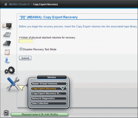
Figure 9-117 Copy Export recovery panel
Copy Export permits the export of all virtual volumes and the virtual volume database to physical volumes, which can then be ejected and saved as part of a data retention policy for disaster recovery. You can also use this function to test system recovery.
See 11.5, “Copy Export overview and Considerations” on page 789 for a detailed explanation of the Copy Export function.
Before you attempt a Copy Export, ensure that all physical media to be used in the recovery is inserted. During a Copy Export recovery, all current virtual and physical volumes are erased from the database and virtual volumes are erased from the cache. Do not attempt a Copy Export operation on a cluster where current data is to be saved.
|
Important: In a grid configuration, each TS7700 Virtualization Engine is considered a separate source. Therefore, only the physical volume exported from a source TS7700 Virtualization Engine can be used for the recovery of that source. Physical volumes exported from more than one source TS7700 Virtualization Engine in a grid configuration cannot be combined to use in recovery. Recovery can only occur to a single cluster configuration; the TS7700 Virtualization Engine used for recovery must be configured as Cluster 0.
|
Secondary Copies
If you create a new secondary copy, the original secondary copy is deleted because it becomes inactive data. For instance, if you modify constructs for virtual volumes that have already been exported and the virtual volumes are remounted, a new secondary physical volume is created. The original physical volume copy is deleted without overwriting the virtual volumes. When the Copy Export operation is rerun, the new, active version of the data is used.
The following fields and options are presented to the user to assist in testing recovery or performing a recovery:
Volser of physical stacked volume for Recovery Test
The physical volume from which the Copy Export recovery attempts to recover the database.
The physical volume from which the Copy Export recovery attempts to recover the database.
Disaster Recovery Test Mode
This option determines whether a Copy Export Recovery is run as a test or to recover a machine that has suffered a disaster. If this box contains a check mark (default status), the Copy Export Recovery runs as a test. If the box is cleared, the recovery process runs in “normal” mode, as when recovering from an actual disaster.
This option determines whether a Copy Export Recovery is run as a test or to recover a machine that has suffered a disaster. If this box contains a check mark (default status), the Copy Export Recovery runs as a test. If the box is cleared, the recovery process runs in “normal” mode, as when recovering from an actual disaster.
When the recovery is run as a test, the content of exported tapes remains unchanged. Additionally, primary physical copies remain unrestored and reclaim processing is disabled to halt any movement of data from the exported tapes. Any new volumes written to the machine are written to newly added scratch tapes and will not exist on the previously exported volumes. This ensures that the data on the Copy Export tapes remains unchanged during the test.
In contrast to a test recovery, a recovery performed in “normal” mode (box cleared) rewrites virtual volumes to physical storage if the constructs change, so that the virtual volume’s data can be put in the correct pools. Also in this type of recovery, reclaim processing remains enabled and primary physical copies are restored, requiring the addition of scratch physical volumes. A recovery run in this mode allows the data on the Copy Export tapes to expire in the normal manner and those physical volumes to be reclaimed.
|
Note: The number of virtual volumes that can be recovered is dependent on the number of FC5270 licenses installed on the TS7700 Virtualization Engine used for recovery. Additionally, a recovery of more than two million virtual volumes must be performed by a TS7740 Virtualization Engine operating with a 3957-V07 and a code level of 8.30.0.xx or higher.
|
Erase all existing virtual volumes during recovery
This check box is shown if virtual volume or physical volume data is present in the database. A Copy Export Recovery operation will erase any existing data. No option exists to retain existing data while performing the recovery. You must check this check box to proceed with the Copy Export Recovery operation.
This check box is shown if virtual volume or physical volume data is present in the database. A Copy Export Recovery operation will erase any existing data. No option exists to retain existing data while performing the recovery. You must check this check box to proceed with the Copy Export Recovery operation.
Submit Click this button to initiate the Copy Export Recovery operation.
Confirm Submission of Copy Export Recovery
You are asked to confirm your decision to initiate a Copy Export Recovery option. Click OK to continue with the Copy Export Recovery operation. Click Cancel to abandon the Copy Export Recovery operation and return to the Copy Export Recovery page.
You are asked to confirm your decision to initiate a Copy Export Recovery option. Click OK to continue with the Copy Export Recovery operation. Click Cancel to abandon the Copy Export Recovery operation and return to the Copy Export Recovery page.
Password Your user password. If you checked the “Erase all existing virtual volumes during recovery” check box, the confirmation message includes the Password field. You must provide a password to erase all current data and proceed with the operation.
Canceling a Copy Export Recovery operation in progress
You can cancel a Copy Export Recovery operation that is in progress from the Copy Export Recovery Status page.
You can cancel a Copy Export Recovery operation that is in progress from the Copy Export Recovery Status page.
Copy Export Recovery Status panel
Use this page to view information about or to cancel a currently running Copy Export recovery operation on an IBM Virtualization Engine TS7700 Cluster.
Figure 9-118 shows the Copy Export Recovery Status panel in the MI.
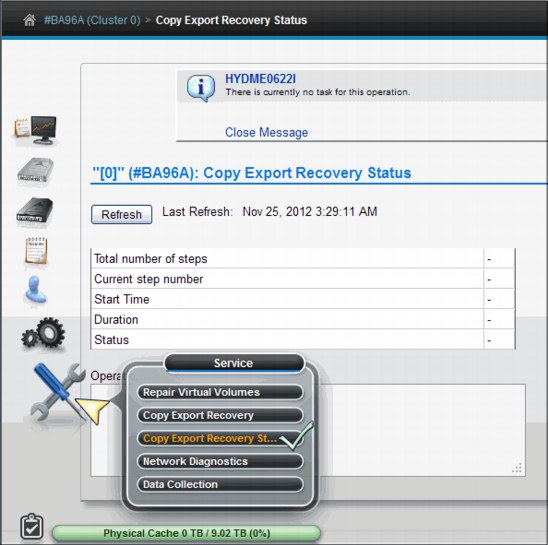
Figure 9-118 Copy Export Recovery Status panel
|
Important: The Copy Export recovery status is only available in a single cluster configuration for a TS7700 grid.
|
The table on this page displays the progress of the current Copy Export recovery operation. This page includes the following information:
Total number of steps
The total number of steps required to complete the Copy Export recovery operation.
The total number of steps required to complete the Copy Export recovery operation.
Current step number
The number of steps completed. This value is a fraction of the total number of steps required to complete, not a fraction of the total time required to complete.
The number of steps completed. This value is a fraction of the total number of steps required to complete, not a fraction of the total time required to complete.
Start time The time stamp for the start of the operation.
Duration The amount of time the operation has been in progress, in hours, minutes, and seconds.
Status The status of the Copy Export recovery operation. The following values are possible:
No task No Copy Export operation is in progress.
In progress The Copy Export operation is in progress.
Complete with success
The Copy Export operation completed successfully.
The Copy Export operation completed successfully.
Canceled The Copy Export operation was canceled.
Complete with failure The Copy Export operation failed.
Canceling The Copy Export operation is in the process of cancellation.
Operation details This field displays informative status about the progress of the Copy Export recovery operation.
Cancel Recovery Click the Cancel Recovery button to terminate a Copy Export recovery operation that is in progress and erase all virtual and physical data. The Confirm Cancel Operation dialog box opens to confirm your decision to cancel the operation. Click OK to cancel the Copy Export recovery operation in progress. Click Cancel to resume the Copy Export recovery operation.
9.2.11 Drive cleaning
The 3592 J1A, TS1120, TS1130, and TS1140 tape drives need periodic cleaning and request cleaning from the TS3500 Tape Library. Automatic cleaning enables the TS3500 Tape Library to respond to any tape drive’s request for cleaning and to begin the cleaning process without operator or TS7700 Virtualization Engine involvement. Automatic cleaning applies to all logical libraries that are configured in the TS3500 Tape Library. Automatic cleaning is required and cannot be disabled when the Advanced Library Management System (ALMS) is enabled. See IBM System Storage TS3500 Tape Library with ALMS Operator Guide, GA32-0594, for more information.
|
Important: ALMS is a requirement for IBM System z attachment. ALMS is always installed and enabled in a TS7700 Virtualization Engine z/OS environment. Therefore, automatic cleaning is enabled.
|
Inserting cleaning cartridges into a TS3500 Tape Library
This section introduces two available methods to insert a cleaning cartridge into the TS3500 Tape Library. The process to insert cleaning cartridges varies depending on the setup of the TS3500 Tape Library. You can use the TS3500 Tape Library Specialist or the library’s operator window to insert a cleaning cartridge.
|
Tip: If virtual I/O slots are enabled, your library automatically imports cleaning cartridges.
|
Using the Tape Library Specialist web interface to insert a cleaning cartridge
To use the Tape Library Specialist web interface to insert a cleaning cartridge into the TS3500 Tape Library, perform the following steps:
1. Open the door of the I/O station and insert the cartridge so that the bar code label faces the interior of the library and the write-protect switch is on the right.
2. Close the door of the I/O station.
3. Type the Ethernet IP address on the URL line of the browser and press Enter. The System Summary window opens.
4. Select Manage Cartridges → I/O Station. The I/O Station window appears.
5. Follow the instructions in the window.
Using the operator window to insert a cleaning cartridge
To use the operator window to insert a cleaning cartridge into the 3584 Tape Library, perform the following steps:
1. From the library’s Activity touch panel, press MENU → Manual Operations → Insert Cleaning Cartridge → Enter. The library displays the message:
Insert Cleaning Cartridge into I/O station before you continue. Do you want to continue?
2. Open the door of the I/O station and insert the cartridge so that the bar code label faces the interior of the library and the write-protect switch is on the right.
3. Close the door of the I/O station.
4. Press Yes. The following message is displayed:
Moving cleaning cartridge
This message is displayed while the library scans for one or more cleaning cartridges in the I/O stations:
– If one or more cleaning cartridges are present, the library moves the cleaning cartridges (one by one) to the lowest empty slots. If the library uses both IBM Linear Tape-Open (LTO) and 3592 tape cartridges, the accessor moves each cleaning cartridge to a storage location that contains similar media (using a separate move operation for each type of media). The library displays the following message:
Insertion of Cleaning Cartridges has completed.
– If no cleaning cartridges are in the I/O stations, the library displays the message:
No cleaning cartridge found in the I/O station.
5. Press Enter to return to the Manual Operations menu.
6. Press Back until you return to the Activity window.
Removing cleaning cartridges from a TS3500 Tape Library
This section describes how to remove a cleaning cartridge by using the TS3500 Tape Library Specialist. You can also use the operator window. See IBM System Storage TS3500 Tape Library with ALMS Operator Guide, GA32-0594, for more information.
To use the TS3500 Tape Library Specialist web interface to remove a cleaning cartridge from the tape library, perform the following steps:
1. Type the Ethernet IP address on the URL line of the browser and press Enter. The System Summary window opens.
3. Select a cleaning cartridge. From the Select Action drop-down menu, select Remove, and then click Go.
4. Look at the Activity pane in the operator window to determine whether the I/O station that you want to use is locked or unlocked. If the station is locked, use your application software to unlock it.
5. Open the door of the I/O station and remove the cleaning cartridge.
6. Close the door of the I/O station.
Determine the cleaning cartridge usage in the TS3500 Tape Library
You can determine the usage of the cleaning cartridge in the same window that is used for
the removal of the cleaning cartridges. See the Cleans Remaining column shown in Figure 9-119.
the removal of the cleaning cartridges. See the Cleans Remaining column shown in Figure 9-119.
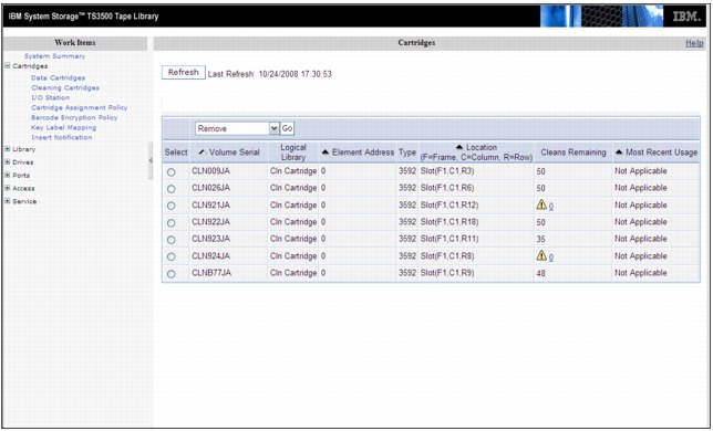
Figure 9-119 TS3500 Tape Library cleaning cartridges
9.3 System-managed tape
This section describes the commands that are used to operate a tape library in a z/OS and system-managed tape environment. It is not intended to replace the full operational procedures in the product documentation. It is a quick reference for the needed Data Facility Storage Management Subsystem (DFSMS) and MVS commands.
9.3.1 DFSMS operator commands
Some of the commands contain “libname” as a variable. In this case, the SMS-defined library name is required. Depending on whether you reference a TS7700 Virtualization Engine composite library, TS7700 Virtualization Engine distributed library, or your native drives’ partition, the output will differ slightly for some of these commands. For more information about DFSMS commands, see z/OS DFSMS Object Access Method Planning, Installation, and Storage Administration Guide for Tape Libraries, SC35-0427.
Information from the TS3500 Tape Library is contained in some of the outputs. However, you cannot switch the operational mode of the TS3500 Tape Library with z/OS commands.
|
Restriction: DFSMS and MVS commands apply only to storage management subsystem (SMS)-defined libraries. The library name defined during the definition of a library in Interactive Storage Management Facility (ISMF) is required for “libname” in the DFSMS commands.
|
The following DFSMS operator commands support the tape library:
•LIBRARY EJECT,volser{,PURGE|KEEP|LOCATION}{,BULK}
This command is used to request the ejection of a volume from a tape library. The following options are available for this command:
– Eject to the convenience I/O station for physical volumes (no additional specification). Delete from the tape library for logical volumes.
– Eject to the bulk output station (BULK or B) for physical volumes. Delete from the tape library for logical volumes.
– Remove the volume record from the tape configuration database (TCDB) (PURGE or P).
– Keep the volume record in the TCDB and update it to indicate that the cartridge has been ejected (KEEP or K). If the record contains information in the SHELF location field, it is not changed. If the SHELF location field is empty, the operator must enter information about the new location as a reply to write to operator with reply (WTOR). The reply can be up to 32 characters long.
– Keep the volume record in the TCDB and update it, including updating the SHELF location even if there is information in this field (LOCATION or L). The operator has to enter the new information as a reply to WTOR.
If none of the variations (PURGE, KEEP, or LOCATION) are indicated in the command, a default decides whether the record is kept or purged. This default can be set separately for each library through the ISMF Library Definition window.
This command is available for the operator to eject single cartridges. Mass ejection of cartridges is usually performed through program interfaces, such as ISMF, a tape management system, or a batch job.
•LIBRARY SETCL, device-number, media-type
This command allows the setting of the media type of the scratch volume that is to be loaded into the integrated cartridge loader (ICL) of the specified tape drive. You must issue the command on the system on which the drive is online. The other hosts are notified when the drive is varied online on the system. With the TS7700 Virtualization Engine, cartridge loaders are simulated and can be set to a media type. However, this approach can influence MVS allocation so care must be taken before using this command.
If the media assignment by this command differs from the current assignment, the ICL is emptied, and the proper cartridges are loaded.
•VARY SMS,LIBRARY(libname),OFFLINE
This command acts on the SMS library, which is referred by libname. That is, it stops tape library actions and gradually makes all of the tape units within this logical library unavailable. The units are varied offline “for library reasons”, which means that they are not accessible because the whole SMS-defined library is offline.
This simple form is a single-system form. The status of the library remains unaffected in other MVS systems.
|
Clarification: This command does not change the operational mode of the TS3500 Tape Library itself. It only applies to the SMS-defined logical libraries.
|
•VARY SMS,LIBRARY(libname),ONLINE
This command is required to bring the SMS-defined library back to operation after it has been offline.
The logical library does not necessarily go offline as a result of an error in a component of the physical library. Therefore, some messages for error situations request that the operator first vary the library offline and then back online. This usually clears all error indications and returns the library back into operation. Of course, this is only the MVS part of error recovery. You must clear the hardware, software, or operational error within the physical library and TS7700 Virtualization Engine before you bring the library online to MVS.
•VARY SMS,LIBRARY(libname,sysname,...),ON/OFF and VARY SMS,LIBRARY(libname,ALL),ON/OFF
This extended form of the VARY command can affect more than one system. The first form affects one or more named MVS systems. The second form performs the VARY action on all systems within the SMSplex.
The VARY SMS command allows the short forms ON as an abbreviation for ONLINE and OFF as an abbreviation for OFFLINE.
•DISPLAY SMS,OAM
This command gives a single line of information about all tape libraries (if present), their tape units, storage cells, and scratch cartridges.
This is the view of the single system where the command was executed. The number of deallocated, online drives is given under the heading AVL DRV (available drives).
If both optical libraries and tape libraries are defined in the SMS configuration, two multiline write to operators (WTOs) are displayed. The first multiline display produced by the library control system (LCS) is the display of optical library information. The second multiline display contains tape library information.
•DISPLAY SMS,LIBRARY(libname|ALL),STATUS
The library status display shows the SMS view of either one SMS-defined library or all SMS-defined libraries. The result contains one line of information for each library. This is a multihost view, which basically indicates whether the SMS-defined library is online, offline, or pending offline.
STATUS is the default parameter.
•DISPLAY SMS,LIBRARY(ALL),DETAIL
The DETAIL display, although a single-system view, gives slightly more information. The display is similar to the result of DISPLAY SMS,OAM, but each library gets its own line of information.
•DISPLAY SMS,LIBRARY(libname),DETAIL
This command provides details about the status of a single library. It is the only command that displays the library state (auto, pause, or manual mode). Reasons for the mode and indications of inoperative parts of the library are given in additional status lines. The following examples show special situations:
– Safety enclosure interlock open
– Vision system not operational
– Convenience output station full
– Out of cleaner volumes
•DISPLAY SMS,STORGRP(grpname|ALL)
There are no new parameters in the Storage Group display command because the optical library request formats are adequate here.
This display command is a general form of a request and gives the total SMS multihost view of the situation. The result is a display of the status of either all Storage Groups (DASD, optical, and tape) or a single Storage Group. There is no format to display one category only.
•DISPLAY SMS,STORGRP(grpname|ALL),DETAIL
The DETAIL display is not much more detailed than the general display. Only the library names of this Storage Group are indicated. This display is, in fact, more restricted than the general display. It gives the view of only one system, the view of its object access method (OAM), as the header line indicates.
The LISTVOL parameter of DISPLAY SMS,STORGRP is not used for tape Storage Groups. Although you can view a volume list through ISMF, a similar listing on the console is too long to be meaningful.
•DISPLAY SMS,VOLUME(volser)
This command displays all information that is stored about the volume in the TCDB (the VOLCAT) and nonpermanent state information, such as “volume mounted on library-resident drive”.
9.3.2 Library LMPOLICY command
Use the LIBRARY LMPOLICY command to assign or change a volume’s policy names outboard at the library. You can use this command only for private, library-resident volumes that reside in a library that supports outboard policy management.
The processing for the LIBRARY LMPOLICY command invokes the Library Control System (LCS) external services FUNC=CUA function. Any errors that the Common User Access (CUA) interface returns can also be returned for the LIBRARY LMPOLICY command. If the change use attribute installation exit (CBRUXCUA) is enabled, the CUA function calls the installation exit. This can override the policy names that you set by using the LIBRARY LMPOLICY command.
The results of this command are specified in the text section of message CBR1086I. To verify the policy name settings and to see whether the CBRUXCUA installation exit changed the policy names you set, display the status of the volume.
The syntax of the LIBRARY LMPOLICY command to assign or change volume policy names is shown in Example 9-2.
Example 9-2 LIBRARY LMPOLICY command syntax
LIBRARY|LI LMPOLICY|LP , volser ,SG= Storage Group name |*RESET*
,SC= Storage Class name |*RESET*
,SC= Storage Class name |*RESET*
,MC= Management Class name |*RESET*
,DC= Data Class name |*RESET*
The following parameters are required:
•LMPOLICY | LP
Specifies a request to set one or more of a private volume’s policy names outboard in the library in which the volume resides. The library must support outboard policy management.
•Volser
Volser specifies the volume serial number of a private volume that resides in a library with outboard policy management support.
•You must specify at least one of the following optional parameters. These parameters can be specified in any order.
– SG={Storage Group name | *RESET*}
Specifies a construct name for the SG parameter. If the request is successful, the construct name becomes the Storage Group for the volume in the TCDB and the Storage Group policy name in the library. If you specify the *RESET* keyword, you are requesting that OAM set the volume’s Storage Group name to blanks in the TCDB, and to the default Storage Group policy in the library, which also consists of blanks.
– SC={storage class name | *RESET*}
Specifies a construct name for the SC parameter. If the request is successful, the construct name becomes the Storage Class policy name for the volume in the library. If you specify the *RESET* keyword, you are requesting that OAM set the volume’s Storage Class name to the default Storage Class policy in the library, which also consists of blanks.
– MC={Management Class name | *RESET*}
Specifies a construct name for the MC parameter. If the request is successful, the construct name becomes the Management Class policy name for the volume in the library. If you specify the *RESET* keyword, you are requesting that OAM set the volume’s Management Class name to the default Management Class policy in the library (blanks).
– DC={Data Class name | *RESET*}
Specifies a construct name for the DC parameter. If the request is successful, the construct name becomes the Data Class policy name for the volume in the library. If you specify the *RESET* keyword, you are requesting that OAM set the volume’s Data Class name to the default Data Class policy in the library, which also consists of blanks.
The values you specify for the SG, SC, MC, and DC policy names must meet the storage management subsystem (SMS) naming convention standards:
•Alphanumeric and national characters only
•Name must begin with an alphabetical or national character ($, *, @, #, or %)
•No leading or embedded blanks
•Eight characters or less
9.3.3 Host Console Request function
The Library Request host console command provides a simple way for an operator to determine the status of the TS7700, to obtain information about the resources of the TS7700, and to perform an operation in the TS7700. It can also be used with automation software to obtain and analyze operational information that can then be used to alert a storage administrator that there is something that must be examined further. Specify the following information for the command:
•A library name, which can be a composite or a distributed library.
•It also allows one to four keywords, with each keyword being a maximum of eight characters.
The specified keywords are passed to the TS7700 identified by the library name to instruct it on what type of information is being requested or which operation is to be performed. Based on the operation requested through the command, the TS7700 then returns information to the host that will be displayed as a multiline write to operator (WTO) message.
The Library Request command for Host Console Request is supported in z/OS V1R6 and later. See OAM authorized program analysis report (APAR) OA20065 and device services APARs OA20066, OA20067, and OA20313. A detailed description of the Host Console Request functions and responses is available in IBM Virtualization Engine TS7700 Series z/OS Host Command Line Request User’s Guide, which is available at the Techdocs website (search for the term TS7700):
Command syntax for the Host Console Request function
The Host Console Request is also referred to as the Library Request command. The syntax of the command is shown in Example 9-3.
Example 9-3 Host Console Request function syntax
>>__ _LIBRARY_ ___REQUEST___,__library_name________________________>
|_LI______| |_REQ_____|
>___ _,keyword1___________________________________________________><
|_,keyword2____________________| |_,L=_ _a______ __|
|_,keyword3____________________| |_name___|
|_,keyword4____________________| |_name-a_|
The following parameters are required:
REQUEST | REQ Specifies a request to obtain information from the TS7700 Virtualization Engine or to perform an outboard operation.
library_name Specifies the library name associated with the TS7700 Virtualization Engine to which the request needs to be directed. The library name specified can be a composite or a distributed library, and which library is applicable depends on the other keywords specified.
keyword1 Specifies which operation is to be performed at the TS7700 Virtualization Engine.
The following parameters are optional. The optional parameters depend on the first keyword specified. Based on the first keyword specified, zero or more of the additional keywords might be appropriate.
keyword2 Specifies additional information in support of the operation specified with the first keyword.
keyword3 Specifies additional information in support of the operation specified with the first keyword.
keyword4 Specifies additional information in support of the operation specified with the first keyword.
L={a | name | name-a}
Specifies where to display the results of the inquiry: the display area (L=a), the console name (L=name), or both the console name and the display area (L=name-a). The name parameter can be an alphanumeric character string.
Specifies where to display the results of the inquiry: the display area (L=a), the console name (L=name), or both the console name and the display area (L=name-a). The name parameter can be an alphanumeric character string.
Note the following information:
•If the request is specific to the composite library, the composite library name must be specified.
•If the request is specific to a distributed library, the distributed library name must be used.
•If a request for a distributed library is received on a virtual drive address on a TS7700 cluster of a separate distributed library, the request is routed to the appropriate cluster for handling and the response is routed back through the requesting device address.
|
Clarification: The specified keywords must be from one to eight characters in length and can consist of alphanumeric characters (A - Z and 0 - 9) and the national character set ($*@#%). A keyword cannot contain any blanks. The only checking performed by the host is to verify that the specified keywords conform to the supported character set. The validity of the keywords themselves and the keywords in combination with each other is verified by the TS7700 Virtualization Engine processing the command.
|
Overview of the Host Console Request functions
Table 9-20 lists all the commands and a short description of each of them.
Table 9-20 Overview of Host Console Request functions
|
Keyword1
|
Keyword2
|
Keyword3
|
Keyword4
|
Description
|
Comp. Lib.
|
Dist. Lib.
|
TS772
or
TS7740
|
|
CACHE
|
|
|
|
Requests information about the current state of the cache and the data managed within it associated with the specific distributed library.
|
N/A
|
Y
|
Both
|
|
COPY
|
ACTIVITY
|
See the User’s Guide
|
|
Requests information about Active Copy jobs.
|
N/A
|
Y
|
TS7720
|
|
COPY
|
SUMMARY
|
|
|
Requests information about all the copy jobs.
|
N/A
|
Y
|
Both
|
|
COPYEXP
|
volser
|
RECLAIM
|
|
Requests that the specified physical volume that has been exported previously in a Copy Export operation be made eligible for priority reclaim.
|
N/A
|
Y
|
TS7740
|
|
COPYEXP
|
volser
|
DELETE
|
|
Requests that the specified physical volume that has been exported previously in a Copy Export operation be deleted from the TS7700 Virtualization Engine database. The volume must be empty.
|
N/A
|
Y
|
TS7740
|
|
GRIDCNTL
|
COPY
|
DISABLE
|
|
Requests that copy operations for the specified distributed library be disabled. Copies that are in progress are allowed to complete, but no new copies using the specified distributed library as the source or target are initiated.
|
N/A
|
Y
|
Both
|
|
GRIDCNTL
|
COPY
|
ENABLE
|
|
Requests that copy operations for the specified distributed library be enabled. Copy operations can again use the specified distributed library as the source or target for copies.
|
N/A
|
Y
|
Both
|
|
LVOL
|
volser
|
|
|
Requests information about a specific logical volume.
|
Y
|
N/A
|
Both
|
|
LVOL
|
volser
|
PREFER MIGRATE
REMOVE
REMOVE
REMOVE
|
PROMOTE
INFO
|
Requests a change in the cache management for a logical volume.
|
N/A
N/A
N/A
N/A
N/A
|
Y
Y
Y
Y
Y
|
Both
TS7740
TS7720
TS7720
TS7720
|
|
LVOL
|
volser
|
COPY
|
KICK
FORCE
|
Kick requests to move a logical volume to the front of the copy queue.
Force puts a copy job against a removed logical volume and promotes it to the front of the copy queue. It is useful when it is required to get a removed volume back into a TS7720 by copying it from another consistent cluster.
|
N/A
|
Y
|
Both
|
|
PDRIVE
|
|
|
|
Requests information about the physical drives and their current usage associated with the specified distributed library.
|
N/A
|
Y
|
TS7740
|
|
POOLCNT
|
00-32
|
|
|
Requests information about the media types and counts, associated with a specified distributed library, for volume pools beginning with the value in keyword2.
|
N/A
|
Y
|
TS7740
|
|
PVOL
|
volser
|
|
|
Requests information about a specific physical volume.
|
N/A
|
Y
|
TS7740
|
|
RECALLQ
|
volser
|
|
|
Requests the content of the recall queue starting with the specified logical volume. Keyword2 can be blank.
|
N/A
|
Y
|
TS7740
|
|
RECALLQ
|
volser
|
PROMOTE
|
|
Requests that the specified logical volume be promoted to the top of the recall queue.
|
N/A
|
Y
|
TS7740
|
|
RRCLSUN
|
ENABLE
DISABLE
STATUS
|
|
|
In response to the RRCLSUN request, the cluster associated with the distributed library will enable, disable, or display the current status of the force residency on recall feature. The TS7700 has a resident on recall function to accelerate format change to the newest media.
|
N/A
|
Y
|
TS7740
|
|
SETTING
|
ALERT,
CACHE,
THROTTLE
DEVALLOC
RECLAIM
CPYCNT
|
Settings to control functions in the grid.
|
N/A
|
Y
|
|||
|
STATUS
|
GRID
|
|
|
Requests information about the copy, reconcile, and ownership takeover status of the libraries in a grid configuration.
|
Y
|
N/A
|
Both
|
|
STATUS
|
GRIDLINK
|
|
|
Requests information about the status and performance of the links between the TS7700 Virtualization Engines in the grid configuration.
|
N/A
|
Y
|
Both
|
|
COPYRFSH
|
volser
|
See the User’s Guide
|
See the User’s Guide
|
Refresh copy policy and queue a copy job on the copy target clusters without mounting or dismounting a volume.
|
N/A
|
Y
|
Both
|
|
GNACNTL
|
ENABLE
DISABLE
STATUS
|
See the User’s Guide
|
See the User’s Guide
|
Request to change TS7700 internal TCP algorithm on grid links.
|
N/A
|
Y
|
Both
|
|
OTCNTL
|
CONFIG
DIST
START
STOP
STAT
|
See the User’s Guide
|
See the User’s Guide
|
Request to move the ownership of the logical volumes in the background.
|
N/A
|
Y
|
Both
|
Overview of the Host Console SETTING request
The SETTING request provides information about many of the current workflow and management settings of the cluster specified in the request and the ability to modify the settings. It also allows alerts to be set for many of the resources managed by the cluster.
In response to the SETTING request, the cluster associated with the distributed library in the request will modify its settings based on the additional keywords specified. If no additional keywords are specified, the request will return the current settings. See Example 9-13 on page 628 for an example of the data returned after the rest of the keyword descriptions.
When a value is specified, lead blanks or zeros are ignored.
|
Important: This command can change several settings on a specified TS7700, which can potentially modify the known behavior of this cluster. If this resource is shared by different clients or environments, a previous agreement is advisable between administrators.
|
ALERT settings
If a second keyword of ALERT is specified, the cluster will set thresholds at which a message is sent to all hosts attached to the cluster and, in a grid configuration, all hosts attached to all clusters. The third keyword specifies which alert threshold will be set and the fourth specifies the threshold value. All messages see the distributed library and will result in the following z/OS host console message:
CBR3750I Message from library distributed library name: Message Text
Thresholds can be set for many of the resources managed by the cluster. For each resource, two settings are provided. One warns that the resource is approaching a value that might result in an impact to the operations of the attached hosts. A second provides a warning that the resource has exceeded a value that might result in an impact to the operations of the attached hosts. When the second warning is reached, the warning message is repeated every 15 minutes.
Figure 9-120 shows the alert thresholds available for various resources that are managed by the cluster.

Figure 9-120 Alert setting diagram
|
Remember: All settings are persistent across machine restarts, service actions, or code updates. The settings are not carried forward as part of disaster recovery from copy-exported tapes or the recovery of a system.
|
The message text includes a message identifier that can be used to automate the capture and routing of these messages. To assist in routing messages to the appropriate individuals for handling, the messages that indicate that a resource is approaching an impact value will use message identifiers in a range of AL0000 - AL4999. Message identifiers in a range of AL5000 - AL9999 will be used for messages that indicate that a resource has exceeded an impact value.
|
Remember: For messages where a variable is included (the setting), the value returned is left-aligned without leading zeroes or right padding, for example:
AL5000 Uncopied data of 1450 GB above high warning limit of 1050 GB.
|
Table 9-21 shows the ALERT thresholds that are supported.
Table 9-21 ALERT thresholds
|
Keyword3
|
Keyword4
|
Description
|
|
COPYHIGH
|
value
|
Uncopied Data High Warning Limit
This is the threshold, in GBs of data in cache, that needs to be copied to other TS7700 Virtualization Engines in a grid configuration, at which point the TS7700 Virtualization Engine will generate a message indicating that the amount of uncopied data has exceeded a high warning limit. For this message to be generated, the amount of uncopied data must be above the value specified in keyword4 for 150 seconds. As long as the amount of uncopied data remains above the threshold, the above warning limit message is repeated every 15 minutes. If the message has been generated and the amount of uncopied data is at or falls below that threshold for 150 seconds, a message is generated indicating that the amount of uncopied data is below the high warning limit.
The default value is 0, which indicates no warning limit is set and no messages are to be generated.
A value greater than the enabled cache size less 500 GB cannot be set. If a value is specified that is not 500 GB lower than the enabled cache size, the threshold is set to the enabled cache size less 500 GB. A value less than 100 GB cannot be set. If a value is specified that is not 100 GB or greater, the threshold is set to 100 GB.
If the uncopied data low warning limit is not zero and a value is specified that is not 100 GB greater than the uncopied data low warning limit, the uncopied data low warning limit will be changed so that it is 100 GB less than the value specified (but never lower than 0).
The message text is shown (xxxxxxxx is the amount of uncopied data, and yyyyyyyy is
the threshold):
•When above the threshold:
AL5000 Uncopied data of xxxxxxxx GB above high warning limit of yyyyyyyy GB.
•When below the threshold:
AL5001 No longer above uncopied data high warning limit of yyyyyyyy GB.
|
|
COPYLOW
|
value
|
Uncopied Data Low Warning Limit
This is the threshold, in GBs of data, in cache that needs to be copied to other TS7700 Virtualization Engines in a grid configuration, at which the TS7700 Virtualization Engine will generate a message indicating that the amount of uncopied data has exceeded a low warning limit. For this message to be generated, the amount of uncopied data must be above the value specified in keyword4 for 150 seconds.
If the message has been generated and the amount of uncopied data is at or falls below that threshold for 150 seconds, a message is generated indicating that the amount of uncopied data is below the low warning limit.
The default value is 0, which indicates no warning limit is set and no messages are to be generated.
If the uncopied data high warning limit is set to 0, the uncopied data low warning limit cannot be set to a value greater than the enabled cache size less 500 GB or to a value less than 100 GB. If a value is specified that is not 500 GB lower than the enabled cache size, the threshold is set to the enabled cache size less 500 GB. If a value is specified that is less than 100 GB, the threshold is set to 100 GB.
If the uncopied data high warning limit is not zero, the uncopied data low warning limit cannot be set to a value greater than the uncopied data high warning limit less 100 GB. If a value is specified that is not 100 GB lower than the uncopied data high warning limit, the threshold is set to the uncopied data high warning limit less 100 GB (but never lower than 0).
The message text is shown (xxxxxxxx is the amount of uncopied data, and yyyyyyyy is the threshold):
•When above the threshold:
AL0000 Uncopied data of xxxxxxxx GB above low warning limit of yyyyyyyy GB.
•When below the threshold:
AL0001 No longer above uncopied data low warning limit of yyyyyyyy GB.
|
|
PDRVCRIT
|
value
|
Available Physical Drive Critical Warning Limit
This is the threshold, in number of physical drives, at which the TS7700 Virtualization Engine will generate a message indicating that the number of available physical drives has fallen below the critical warning limit. For this message to be generated, the number of available physical drives must be below the value specified in keyword4 for 15 minutes.
As long as the number of available physical drives is below the threshold, the “below the threshold” message is repeated every 15 minutes. If the message has been generated and the number of available physical drives is at or has risen above that threshold for 15 minutes, a message is generated indicating that the number of available physical drives is above the critical warning limit.
The default value is 0, which indicates no warning limit is set and no messages are to be generated.
A value greater than the number of installed physical drives minus 1 cannot be set. If a value is specified that is greater than the number of installed physical drives minus 1, the threshold is set to the number of installed physical drives minus 1. A value less than 3 cannot be set. If a value is specified that is less than 3, the threshold is set to 3.
If the available physical drive low warning limit is not zero and a value is specified that is not 1 less than the available physical drive low warning limit, the available physical drive low warning limit will be changed so that it is 1 more than the value specified (but never more than the number of installed physical drives).
The message text is shown (xx is the number of available drives, and yy is the threshold):
•When fallen below the threshold:
AL5004 Available physical drives of xx is below critical limit of yy.
•When risen above the threshold:
AL5005 Available physical drives no longer below critical limit of yy.
|
|
PDRVLOW
|
value
|
Available Physical Drive Low Warning Limit
This is the threshold, in number of physical drives, at which the TS7700 Virtualization Engine will generate a message indicating that the number of available physical drives has fallen below the low warning limit. For this message to be generated, the number of available physical drives must be below the value specified in keyword4 for 15 minutes.
If the message has been generated and the number of available physical drives is at or has risen above that threshold for 15 minutes, a message is generated indicating that the number of available physical drives is above the low warning limit.
The default value is 0, which indicates no warning limit is set and no messages will be generated.
If the available physical drive critical warning limit is set to 0, the available physical drive low warning limit cannot be set to a value greater than the number of installed physical drives or less than 3. If a value is specified that is greater than the number of installed physical drives, the threshold is set to the number of installed physical drives. If a value is specified that is less than 3, the threshold is set to 3.
If the available physical drive critical warning limit is not zero and a value is specified that is not 1 greater than the available physical drive critical warning limit, the available physical drive low warning limit will be changed so that it is 1 more than the available physical drive critical warning limit (but never greater than the number of installed physical drives).
The message text is shown (xx is the number of available drives, and yy is the threshold):
•When fallen below the threshold:
AL0004 Available physical drives of xx is below low limit of yy.
•When risen above the threshold:
AL0005 Available physical drives no longer below low limit of yy.
|
|
PSCRCRIT
|
value
|
Physical Scratch Volume Critical Warning Limit
This is the threshold, in number of scratch physical volumes, at which the TS7700 Virtualization Engine will generate a message indicating that the number of available scratch physical volumes has fallen below the critical warning limit. For this message to be generated, the number of available physical scratch volumes for one of the active general pools (pools 1 - 32) must be below the value specified in keyword4 for 16 minutes. Available volumes include those in pool 0 if borrowing is allowed for the pool.
All media types allowed for borrowing are considered. As long as the number of scratch physical volumes is below the threshold, the below the threshold message is repeated every 16 minutes. If the message has been generated and the number of available physical scratch volumes for the pool is at or has risen above that threshold for 16 minutes, a message is generated indicating that the number of available physical scratch volumes is above the critical warning limit.
The default value is 0, which indicates no warning limit is set and no messages will be generated.
A value greater than 190 cannot be set. If a value is specified that is greater than 190, the threshold is set to 190. A value less than 5 cannot be set. If a value is specified that is less than 5, the threshold is set to 5.
If the physical scratch volume low warning limit is not zero and a value is specified that is not 10 less than the physical scratch volume low warning limit, the physical scratch volume low warning limit will be changed so that it is 10 more than the value specified (but never greater than 200).
The message text is shown (xxx is the number of available physical scratch volumes, yyy is the threshold, and zz is the pool number):
•When fallen below the threshold:
AL5006 Available physical scratch volumes of xxx below critical limit of yyy for pool zz.
•When risen above the threshold:
AL5007 Available physical scratch volumes no longer below critical limit of yyy for pool zz.
Tip: The TS7700 Virtualization Engine will enter panic reclaim if the number of scratch volumes available to a defined pool is less than 2, including ones that it can borrow from pool 0.
|
|
PSCRLOW
|
value
|
Physical Scratch Volume Low Warning Limit
This is the threshold, in number of scratch physical volumes, at which the TS7700 Virtualization Engine will generate a message indicating that the number of available scratch physical volumes has fallen below the low warning limit. For this message to be generated, the number of available physical scratch volumes for one of the active general pools (pools 1 - 32) must be below the value specified in keyword4 for 16 minutes. Available volumes include those in pool 0 if borrowing is allowed for the pool.
All media types allowed for borrowing are considered. If the message has been generated and the number of available physical scratch volumes for the pool and media type is at or has risen above that threshold for 16 minutes, a message is generated indicating that the number of available physical scratch volumes is above the low warning limit.
The default value is 0, which indicates no warning limit is set and no messages are to be generated.
If the physical scratch volume critical warning limit is set to 0, the physical scratch volume low warning limit cannot be set to a value greater than 200 or less than 5. If a value is specified that is greater than 200, the threshold is set to 200. If a value is specified that is less than 5, the threshold is set to 5.
If the physical scratch volume critical warning limit is not zero and a value is specified that is not 10 greater than the physical scratch volume critical warning limit, the physical scratch volume low warning limit will be changed so that it is 10 more than the physical scratch volume critical warning limit (but never greater than 200).
The message text is shown (xxx is the number of available physical scratch volumes, yyy is the threshold, and zz is the pool number):
•When fallen below the threshold:
AL0006 Available physical scratch volumes of xxx below low limit of yyy for pool zz.
•When risen above the threshold:
AL0007 Available physical scratch volumes no longer below low limit of yyy for pool zz.
Tip: The TS7700 Virtualization Engine will enter panic reclaim if the number of scratch volumes available to a defined pool is less than 2, including ones that it can borrow from pool 0.
|
|
RESDHIGH
|
value
|
Resident Data High Warning Limit
This is the threshold, in gigabytes of resident data, at which the TS7700 Virtualization Engine will generate a message indicating that the amount of resident data has exceeded a high warning limit. For this message to be generated, the amount of resident data must be above the value specified in keyword4 for 150 seconds. As long as the amount of resident data remains above the threshold, the above warning limit message is repeated every 15 minutes.
If the message has been generated and the amount of resident data is at or falls below that threshold for 150 seconds, a message is generated indicating that the amount of resident data is below the high warning limit.
The default value is 0, which indicates no warning limit is set and no messages are to be generated.
A value greater than the enabled cache size less 500 GB cannot be set. If a value is specified that is not 500 GB lower than the enabled cache size, the threshold is set to the enabled cache size less 500 GB. A value less than 100 GB cannot be set. If a value is specified that is not 100 GB or greater, the threshold is set to 100 GB.
If the resident data low warning limit is not zero and a value is specified that is not 100 GB greater than the resident data low warning limit, the resident data low warning limit will be changed so that it is 100 GB less than the value specified (but never lower than 0).
The message text is shown (xxxxxxxx is the amount of resident data, and yyyyyyyy is the threshold):
•When above the threshold:
AL5008 Resident data of xxxxxxxx GB above high warning limit of yyyyyyyy GB.
•When below the threshold:
AL5009 No longer above resident data high warning limit of yyyyyyyy GB.
Tip: For a TS7740 Virtualization Engine, resident data is the data that has not been copied to back-end physical volumes. For a TS7720 Virtualization Engine, resident data is the data that occupies the cache.
|
|
RESDLOW
|
Value
|
Resident Data Low Warning Limit
This is the threshold, in gigabytes of resident data, at which the TS7700 Virtualization Engine will generate a message indicating that the amount of resident data has exceeded a low warning limit. For this message to be generated, the amount of resident data must be above the value specified in keyword4 for 150 seconds.
If the message has been generated and the amount of resident data is at or falls below that threshold for 150 seconds, a message is generated indicating that the amount of resident data is below the low warning limit.
The default value is 0, which indicates no warning limit is set and no messages are to be generated.
If the resident data high warning limit is set to 0, the resident data low warning limit cannot be set to a value greater than the enabled cache size less 500 GB or to a value less than 100 GB. If a value is specified that is not 500 GB lower than the enabled cache size, the threshold is set to the enabled cache size less 500 GB. If a value is specified that is less than 100 GB, the threshold is set to 100 GB.
If the resident data high warning limit is not zero, the resident data low warning limit cannot be set to a value greater than the resident data high warning limit less 100 GB. If a value is specified that is not 100 GB lower than the resident data high warning limit, the threshold is set to the resident data high warning limit less 100 GB (but never lower than 0).
The message text is shown (xxxxxxxx is the amount of resident data, and yyyyyyyy is the threshold):
•When above the threshold:
AL0008 Resident data of xxxxxxxx GB above low warning limit of yyyyyyyyy GB.
•When below the threshold:
AL0009 No longer above resident data low warning limit of yyyyyyyy GB.
Tip: For a TS7740 Virtualization Engine, resident data is the data that has not been copied to back-end physical volumes. For a TS7720 Virtualization Engine, resident data is the data that occupies the cache.
|
|
PCPYLOW
|
Value
|
Pending Copy Low
This is the threshold in GBs of volumes in the copy queue. The following limitations are for this alarm to be set:
•The difference between the critical value (described below) and the low value must be equal to or bigger than 500.
•The lower value for this field must be equal to or bigger than 500 GB.
When adjusting the lower/high value, if the difference is lower than 500, the lower value is decreased automatically to accommodate the difference.
The message text is presented (xx is the distributed library name, yyyy is total pending copy GB, and zzzz is the threshold of the alert) when the level falls below or rises above the threshold:
•AL0011 Distributed Library xx has successfully fallen below the inbound copy backlog low warning limit of zzzz GB.
•AL0010 Distributed Library xx has a total pending inbound copy backlog of yyyy GB which is above the low warning limit of zzzz GB.
|
|
PCPYCRIT
|
Value
|
Pending Copy Critical
This is the upper limit in GB for volumes in the copy queue. The difference between the critical value (described above) and the low value must be equal to or bigger than 500. When adjusting the lower/high value, if the difference is lower than 500, the lower value is decreased automatically to accommodate the difference. The same messages, AL0011 and AL0010, are presented (see above in the PCPYLOW keyword section).
|
|
DEFDEG
|
ENABLE
DISABLE
|
Synchronous deferred or the immediate deferred condition occurs:
•When the ENABLE keyword is specified, the degraded state is reported to the host through the operational state change attention.
•When the DISABLE keyword is specified, the degraded state is not reported to the host through the operational state change attention.
The default setting is ENABLE. The command is acceptable only when all clusters in the grid are at code level 8.30.xx.xx or higher. The following messages are shown:
G0005 Distributed Library xx has entered the immediate deferred state and G0032 Distributed Library xx has entered the synchronous deferred state due to volser yyyyyy are generated regardless of the DEFDEG setting.
|
|
REMOVMSG
|
ENABLE
DISABLE
|
Prevents a distributed library (TS7720) from reporting Automatic Removal start and stop events to the MI and operator messages to the host when Auto Removal occurs.
When the ENABLE keyword is specified, an event will be posted to the TS7700 MI when automatic removal of logical volumes starts and another event will be posted when it stops. An associated host message will be sent for each event as well. When the DISABLE keyword is specified, no event or message associated with automatic removal of logical volumes will be posted in the TS7700 MI or sent to the host.
The default setting is ENABLE.
This command is acceptable only on TS7720 with code level 8.21.0.144 or higher.
|
CACHE settings
If the second keyword of CACHE is specified, the cluster modifies how it controls the workflow and content of the TVC.
The supported CACHE settings are shown in Table 9-22.
Table 9-22 CACHE settings
|
Keyword3
|
Keyword4
|
Description
|
|
COPYFSC
|
ENABLE,
DISABLE
|
Copies To Follow Storage Class Preference
When the ENABLE keyword is specified, the logical volumes copied into the cache from a peer TS7700 Virtualization Engine are managed using the actions defined for the Storage Class construct associated with the volume as defined at the TS7700 Virtualization Engine receiving the copy.
When the DISABLE keyword is specified, the logical volumes copied into the cache from a peer TS7700 Virtualization Engine are managed as PG0 (prefer to be removed from cache).
The default is disabled.
|
|
PMPRIOR
|
value
|
Premigration Priority Threshold
This is the threshold, in gigabytes of unpremigrated data, at which the TS7700 Virtualization Engine will begin increasing the number of premigration tasks that will be allowed to compete with host I/O for cache and processor cycles.
The amount of unpremigrated data must be above the value specified in keyword4 for 150 seconds before the additional premigration tasks are added. As the amount of data to premigrate continues to grow above this threshold setting, so do the number of enabled premigration tasks until the maximum is reached. The maximum is the number of available physical drives minus 1 (the TS7700 Virtualization Engine always keeps a minimum of one drive available for recalls).
If the amount of unpremigrated data subsequently falls below this threshold for at least 150 seconds, the number of premigration tasks might be reduced depending on host I/O demand. If I/O host demand is high, the number of premigration tasks will eventually be reduced to a minimum of one.
The default value is 1600.
If a value is specified that is higher than the premigration throttling threshold value, it is set to the premigration throttling threshold value.
Tip: Do not change this setting from the default unless you understand the impact that the change will have on the operation of the TS7700 Virtualization Engine. Raising the value might increase the length of time a peak write rate might be accepted, but also means that more data is solely resident in the cache and delays copying that data to physical tape.
|
|
PMTHLVL
|
value
|
Premigration Throttling Threshold
This is the threshold, in gigabytes of unpremigrated data, at which the TS7700 Virtualization Engine will begin introducing a delay in responding to host write operations on all virtual tape device addresses of the TS7700 Virtualization Engine.
The amount of unpremigrated data must be above the value specified in keyword4 for 150 seconds before the delay is introduced. The amount of delay begins with a few milliseconds and increases to 2000 milliseconds as the amount of unpremigrated data approaches the total cache capacity. The amount of unpremigrated data must fall below this threshold for 150 seconds for all delay to be removed.
The default value is 2000.
A value greater than the enabled cache size less 500 GB cannot be set. If a value is specified that is not 500 GB lower than the enabled cache size, the threshold is set to the enabled cache size less 500 GB.
Tip: Do not change this setting from the default unless you understand the impact that the change will have on the operation of the TS7700 Virtualization Engine. Raising the value might increase the length of time a peak write rate might be accepted, but also means that more data is solely resident in the cache and delays copying that data to physical tape.
|
|
RECLPG0
|
ENABLE,
DISABLE
|
Recalls Preferred to be Removed from Cache
When the ENABLE keyword is specified, logical volumes that are recalled into cache are managed as PG0 (prefer to be removed from cache). This overrides the actions defined for the Storage Class associated with the recalled volume.
When the DISABLE keyword is specified, logical volumes that are recalled into cache are managed using the actions defined for the Storage Class construct associated with the volume as defined at the TS7700 Virtualization Engine.
The default is disabled.
|
|
REMOVE
|
ENABLE,
DISABLE |
Automatic removal starts when cache usage size crosses the removal threshold.
When the ENABLE keyword is specified, the automatic removal will be enabled on this disk-only cluster.
When the DISABLE keyword is specified, the automatic removal will be disabled on this disk-only cluster.
The default value is enabled.
|
|
REMVTHR
|
Value
|
Automatic removal starts when the cache usage size crosses the removal threshold.
When automatic removal is enabled on this disk-only cluster, logical volume removal will start when the free cache space is below the removal threshold plus 1000 GB (1000 GB is the out-of-cache warning threshold).
The default value is 3000 (in GB). A value of 2000 to 10000 can be set. As an example, a value of 2000 means that the TS7700 will start the automatic removal when there is less than 3000 GB (2000 GB + 1000 GB) of free cache space. If a value less than 2000 is given, it will be set to 2000. If a value more than 10000 is given, it will be set to 10000.
|
THROTTLE settings
If a second keyword of THROTTLE is specified, the cluster will modify how it controls the data flow rates into and out to the cluster.
Supported THROTTLE settings are shown in Table 9-23.
Table 9-23 THROTTLE settings
|
Keyword3
|
Keyword4
|
Description
|
|
COPYFT
|
ENABLE,
DISABLE
|
Full Cache Copy Throttling
When the ENABLE keyword is specified, throttling when the cache is full of uncopied data to other TS7700 Virtualization Engines is enabled.
When the DISABLE keyword is specified, throttling when the cache is full of uncopied data to other TS7700 Virtualization Engines is disabled.
The default is enabled.
Tip: Full Cache Copy Throttling is also disabled for 24 hours after one of the other TS7700 Virtualization Engines has been in service mode. This is to prevent immediate host throttling when the TS7700 Virtualization Engine being serviced is returned to use.
|
|
DCOPYT
|
value
|
Deferred Copy Throttle
This is a delay, in milliseconds, that the TS7700 will introduce for every 256 KB copy transfer for all deferred mode copy tasks in which it is the source. The delay is introduced when the TS7700 detects that it is in a period of high host write workload. The criteria the TS7700 uses is if the data rate into the cache exceeds 100 MB/s (this is after compression) or if the idle processor cycles of the TS7700 fall below 15%. A value of 0 to 250 milliseconds can be set. The default value is 125 milliseconds.
|
|
ICOPYT
|
ENABLE,
DISABLE
|
Immediate Copy Throttling
When the ENABLE keyword is specified, immediate copy throttling is enabled.
The depth of the immediate copy queue and the amount of time copies have been in the queue are examined to determine whether the throttle must be applied.
When the DISABLE keyword is specified, immediate copy throttling is disabled.
The default is enabled.
|
|
DCTAVGTD
|
value
|
Deferred Copy Throttling Average Threshold
This value is used to determine at what average compressed Host I/O rate to keep deferred copy throttling delayed. The average compressed host I/O rate is an average of the I/O rate over a 20-minute period. When this average compressed rate is exceeded, the deferred copies are delayed as specified by the DCOPYT value. The default value is 100 in MBps. A value of 0 will set the threshold to the default. A value of 1 - 500 can be set.
|
DEVALLOC (Device Allocation) settings
If a second keyword of DEVALLOC is specified, the cluster will modify how it performs scratch allocation assistance (SAA) or device allocation assistance (DAA) for private tapes.
SAA was introduced in R2.0. It is an extension to DAA and works in co-existence with your defined Management Class values where candidate clusters for scratch mounts are entered. SAA must be enabled in the host operating system. SAA directs new workloads to particular clusters. An example is to direct a DFSMShsm Migration Level 2 (ML2) workload to the TS7720 in a mixed grid, as shown in Figure 9-121.

Figure 9-121 SAA on mixed grid
Device allocation assistance (DAA) is a function that allows the host to query the TS7700 Virtualization Engine to determine which clusters must be preferred for a private (specific) mount request. When enabled, DAA returns to the host a ranked list of clusters (the preferred cluster is listed first) that determines for a specific VOLSER which cluster, either a TS7740 or a TS7720, is best to use for device allocation.
For details about SAA and DAA, see Chapter 10, “Performance and monitoring” on page 653. The DEVALLOC settings shown in Table 9-24 are supported.
Table 9-24 DEVALLOC settings
|
Keyword3
|
Keyword4
|
Description
|
|
SCRATCH
|
ENABLE,
DISABLE
|
Device Allocation Assist for Scratch Volumes
If a keyword4 of ENABLE is specified, a domain at code level 8.20.x.x or greater shall process device allocation assist commands for scratch volumes. A keyword4 of DISABLE will remove the capability to process device allocation assist commands for scratch volumes.
The default is disabled.
|
|
PRIVATE
|
ENABLE, DISABLE
|
Device Allocation Assist for Private Volumes
If a keyword4 of DISABLE is specified, a domain at code level 8.20.x.x or greater inhibits processing device allocation assist commands for private volumes. A keyword4 of ENABLE allows the capability to process device allocation assist commands for private volumes.
The default is enabled.
|
Reclaim settings
If a second keyword of RECLAIM is specified, the cluster will modify how the reclaim background tasks controls the workflow and content of the TVC.
|
Note: Also, if a valid RECLAIM request is received while reclaims are inhibited, that request will take effect as soon as reclaims are no longer inhibited by the Inhibit Reclaim schedule.
|
The RECLAIM settings shown in Table 9-25 are supported.
Table 9-25 RECLAIM settings
|
Keyword3
|
Keyword4
|
Description
|
|
RCLMMAX
|
value
|
Reclaim Maximum Tasks Limit
Sometimes, you might want to have fewer reclaims running and use the service resource for other activities in the cluster. If keyword3 is specified as RCLMMAX, the cluster can be directed to limit the maximum number of reclaims to a certain value. The number of available tasks is closely related to the number of physical drives connected to the cluster:
•Three - five drives give a maximum number of reclaim tasks of 1
•Six - seven drives give a maximum number of reclaim tasks of 2
•Eight - nine drives give a maximum number of reclaim tasks of 3
•Ten - 11 drives give a maximum number of reclaim tasks of 4
•Twelve - 13 drives give a maximum number of reclaim tasks of 5
•Fourteen - 15 drives give a maximum number of reclaim tasks of 6
•Sixteen drives give a maximum number of reclaim tasks of 7
|
CPYCNT (Copy Thread Count) settings
If a second keyword of CPYCNT is specified, the domain will modify how many concurrent threads are allowed to process either RUN or Deferred copies over the grid.
The CPYCNT settings shown in Table 9-26 are supported.
Table 9-26 CPYCNT settings
|
Keyword3
|
Keyword4
|
Description
|
|
RUN
|
Number of Concurrent RUN Copy Threads
|
The number of concurrent copy threads for processing RUN copies
The allowed values for copy thread counts are 5 - 128.
The default value is 20 for clusters with two 1 Gb Ethernet links, and 40 for clusters with four 1 Gb Ethernet links or two 10 Gb Ethernet links.
|
|
DEF
|
Number of Concurrent Deferred Copy Threads
|
The number of concurrent copy threads for processing Deferred copies
The allowed values for copy thread counts are 5 - 128.
The default value is 20 for clusters with two 1 Gb Ethernet links, and 40 for clusters with four 1 Gb Ethernet links or two 10 Gb Ethernet links.
|
On Table 9-27, we list the supported settings for COPY.
Table 9-27 Copy settings
|
Keyword3
|
Keyword4
|
Description
|
|
IMMSNS
|
All
UNEXP
NONE
|
Immediate-Deferred State Reporting Method
This is the control method to report the immediate-deferred state in the
CCW (RUN) ERA35 sense data. With Release 1.6 code, TS7700
reports all the immediate-deferred state in the CCW (RUN) ERA35
sense data. Since Release 1.7 pre-general availability (PGA) 5 (8.7.0.155) or 2.0 codes, the reporting method can be modified:
•If keyword4 of ALL is specified, all the immediate-deferred state is reported in the ERA35 sense data the same as Release 1.6.
•If keyword4 of UNEXP is specified, only the immediate-deferred state induced unexpectedly is reported in the ERA35 sense data.
•If keyword4 of NONE is specified, no immediate-deferred state is reported in the ERA35 sense data except the case where no valid source to copy is available.
•The default value is NONE.
See IBM Virtualization Engine TS7700 Series Best Practice Understanding, Monitoring and Tuning the TS7700 Performance, WP101465, which is available at http://www.ibm.com/support/techdocs for more information.
|
|
TIMEOUT
|
value
|
Volume Copy Timeout Time
This is the timeout value in minutes for logical volume copies between clusters to complete. A volume copy between TS7700s has a timeout value. If a volume copy
starts and does not finish in the allotted time, it is canceled and returned
to the copy queue for retry. Prior to Release 2.0 codes, the timeout value is fixed at 180 minutes. Starting with Release 2.0 codes, the timeout value can be modified.
The default value is 180 minutes; however, a larger timeout value may
be needed when copy tasks increase or limited bandwidth is available.
The allowed values for copy timeout are from 30 - 999 minutes.
|
Link failover settings
If a second keyword of LINK is specified, the cluster will modify how to react in a link failure during a remote mount.
Table 9-28 on page 623 shows the supported settings for LINK.
Table 9-28 LINK settings
|
Keyword 3
|
Keyword4
|
Description
|
|
FAILOVER
|
ENABLE
DISABLE
|
IP Link Failover for Remount Mounts
If keyword4 of ENABLE is specified, a cluster at code level 8.21.x.x or greater shall use the failover capability in a link failure during a remote mount.
Keyword4 of DISABLE shall remove the failover capability.
The default behavior is ENABLE.
|
Delexp (Delete Expire) count settings
In response to a request where a composite library is specified, the Delete-Expire setting will be modified as described in Table 9-29.
Table 9-29 Delete-Expire setting
|
Keyword3
|
Keyword4
|
Description
|
|
COUNT
|
Value
|
Delete Expire Count
The Delete Expire Count can be set to any value from the default value of 1000 to the maximum value of 2000.
If the keyword4 specified value is smaller than the default, the default value will be set.
If the keyword4 specified value is greater than the maximum, it will be set at the maximum value.
|
Examples of the Host Console Request functions
Let us examine examples of the commands and the responses retrieved.
CACHE command
Example 9-4 shows the CACHE command.
Example 9-4 Library request command CACHE
LI REQ,BARR68A,CACHE
CBR1020I PROCESSING LIBRARY COMMAND: REQ,BARR68A,CACHE.
CBR1280I LIBRARY BARR68A REQUEST. 149
KEYWORDS: CACHE
----------------------------------------------------------------------
TAPE VOLUME CACHE STATE V3
INSTALLED/ENABLED GBS 7000/ 7000
CACHE ENCRYPTION STATUS: ENABLED-INTERNAL
PARTITION ALLOC USED PG0 PG1 PMIGR COPY PMT CPYT
0 7000 6586 550 6029 2092 1 0 0
1 0 0 0 0 0 0 0 0
2 0 0 0 0 0 0 0 0
3 0 0 0 0 0 0 0 0
4 0 0 0 0 0 0 0 0
5 0 0 0 0 0 0 0 0
6 0 0 0 0 0 0 0 0
7 0 0 0 0 0 0 0 0
The response shows the following information:
•Version (V3). Version was increased to 2 at code level 8.21.x.x and to 3 at 8.30.x.x.
•Number of gigabytes (GB) installed and enabled
•Cache Encryption Status
•One line per partition for future partition support
•Allocated GB and used GB in the cache and how they are split between PG0 and PG1
•Number of GB that must be premigrated
•Number of GB that must be copied to another cluster
•Premigration and copy throttling values in msec
GRIDCNTL command
Example 9-5 shows the GRIDCNTL DISABLE command.
Example 9-5 Library request command GRIDCNTL DISABLE
LI REQ,BARR68,GRIDCNTL,DISABLE
CBR1020I PROCESSING LIBRARY COMMAND: REQ,BARR68,GRIDCNTL,DISABLE
CBR1280I LIBRARY BARR68 REQUEST. 509
KEYWORDS: GRIDCNTL,DISABLE
------------------------------------------------------------
GRID COPY CAPABILITIES V2
DISABLED FOR SOURCE AND TARGET COPIES
The response from GRIDCNTL DISABLE shows that copies have been stopped.
Example 9-6 shows the GRIDCNTL ENABLE command.
Example 9-6 Library request command GRIDCNTL ENABLE
LI REQ,BARR68,GRIDCNTL,ENABLE
CBR1020I PROCESSING LIBRARY COMMAND: REQ,BARR68,GRIDCNTL,ENABLE
CBR1280I LIBRARY BARR68 REQUEST. 509
KEYWORDS: GRIDCNTL,ENABLE
------------------------------------------------------------
GRID COPY CAPABILITIES V2
ENABLED FOR SOURCE AND TARGET COPIES
The response from GRIDCNTL DISABLE shows that copies have been restarted.
LVOL command
Example 9-7 shows the LVOL command.
Example 9-7 Library request command LVOL
LI REQ,BARR68,LVOL,693023
CBR1020I PROCESSING LIBRARY COMMAND: REQ,BARR68,LVOL,693023.
CBR1280I LIBRARY BARR68 REQUEST. 509
KEYWORDS: LVOL,693023
------------------------------------------------------------
LOGICAL VOLUME INFORMATION V2
LOGICAL VOLUME: 693023
MEDIA TYPE: CST
COMPRESSED SIZE (MB): 392
MAXIMUM VOLUME CAPACITY (MB): 0
CURRENT OWNER: Pesto
MOUNTED LIBRARY:
MOUNTED VNODE:
MOUNTED DEVICE:
TVC LIBRARY: Pesto
MOUNT STATE:
CACHE PREFERENCE: PG1
CATEGORY: 000F
LAST MOUNTED (UCT): 2006-05-23 19:34:23
LAST MODIFIED (UTC): 2006-05-23 19:35:54
LAST MOUNTED VNODE: 00
LAST MODIFIED DEVICE: 37
TOTAL REQUIRED COPIES: 2
KNOWN CONSISTENT COPIES: 2
KNOWN REMOVED COPIES: 1
IMMEDIATE-DEFERRED: N
DELETE EXPIRED: N
RECONCILIATION REQUIRED: N
GROUP NAME: ABCDEFGH
LWORM VOLUME: N
---------------------------------------------------------------------
LIBRARY RQ CACHE PRI PVOL SEC PVOL COPY ST COPY Q COPY MD REM
Pesto N N JA6321 ------ CMPT - RUN Y
Squint N N JA4238 ------ CMPT - DEF N
Celeste N N JB0450 ------ CMPT - RUN N
The response from LVOL shows detailed information about the logical volume. The response shows the following information:
•Whether a logical volume is ECCST or CST, and the size of the volume
•Number of copies and VOLSER of physical volumes where the logical volume resides
•Copy policy used
PVOL command
Example 9-8 shows the PVOL command.
Example 9-8 Library request command PVOL
LI REQ,BARR68A,PVOL,JA5313
CBR1020I PROCESSING LIBRARY COMMAND: REQ,BARR68A,PVOL,JA5313.
CBR1280I LIBRARY BARR68A REQUEST. 225
KEYWORDS: PVOL,JA5313
----------------------------------------------------------------
PHYSICAL VOLUME INFORMATION V2
PHYSICAL VOLUME: JA5313
MEDIA TYPE: JA
DRIVE MODE: E05
FORMAT: TS7700
VOLUME STATE: READ-WRITE
CAPACITY STATE: FILLING
CURRENT POOL: 2
MBYTES WRITTEN: 140718
% ACTIVE DATA: 100.0
LAST INSERTED: 2007-03-16 20:06:06
WHEN EXPORTED: N/A
MOUNTS: 2
LOGICAL VOLUMES: 374
ENCRYPTED: N
The response from PVOL shows detailed information about the logical volume:
•Media type, drive mode, format of the volume, and volume state (READ-WRITE)
•Capacity in MB, valid data in percent, and number of logical volumes
•Whether the physical volume is exported and whether it is encrypted
POOLCNT command
Example 9-9 shows the POOLCNT command.
Example 9-9 Library request command POOLCNT
LI REQ,BARR68A,POOLCNT
CBR1020I PROCESSING LIBRARY COMMAND: REQ,BARR68A,POOLCNT.
CBRXLCS SCRATCH PROCESSING FAILED FOR: V66654 RC = 0004 RSN = 0004
CBR1280I LIBRARY BARR68A REQUEST. 441
KEYWORDS: POOLCNT
----------------------------------------------------------------------
PHYSICAL MEDIA COUNTS V1
POOL ......MEDIA EMPTY FILLING FULL ERASE ROR ...UNAVAIL CXPT
0 .... JA ...... 1618
1 ...JA ........3 ......1.....576 ....0.......0.......0 ....... 0
2 ... JA ...... 2...... 8 ... 712 ... 7 ..... 0 .... 0
The response from POOLCNT shows detailed information about each physical volume pool:
•Detailed information shown from each pool
•Details about media type, and volumes that are empty, filling, or full
•Volumes eligible for erasure
•Volumes that are in the read-only state, unavailable, or in the Copy Export state
RECALLQ command
Example 9-10 shows the RECALLQ command.
Example 9-10 Library request command RECALLQ
LI REQ,BARR68A,RECALLQ
CBR1020I PROCESSING LIBRARY COMMAND: REQ,BARR68A,RECALLQ.
CBR1280I LIBRARY BARR68A REQUEST. 820
KEYWORDS: RECALLQ
---------------------------------------------------------
RECALL QUEUE V2
POS LVOL PVOL1 PVOL2 TIME
IP L00121 AB0456 175
IP L99356 AA0350 201
SC Y30458 AB0456 148
SC L54019 AA0350 145
1 L67304 AC0101 135
2 T09356 AD5901 P00167 102
The response from RECALLQ on the distributed library shows detailed information about the logical volume recall queue:
•The recall is in progress for volume L00121 and L99356.
•Volumes Y30458 and L54019 have a recall scheduled, which means a RECALLQ,volser,PROMOTE has been issued.
•Volume L67304 is in position 1 for recall and has been in the recall queue for 135 seconds.
•Volume T09365 spans from physical volume AD5901 to P00167.
STATUS command
Example 9-11 on page 627 shows the STATUS GRID command.
Example 9-11 Library request command STATUS,GRID
GRID STATUS V2
COMPOSITE LIBRARY VIEW
IMMED-DEFERRED OWNERSHIP-T/O RECONCILE HCOPY
LIBRARY STATE NUM MB MODE NUM NUM ENB
TS001A ON 0 0 - 0 0 Y
TS001B SVC 12 8713 SOT 24 12 N
TS001C ON 0 0 - 0 0 Y
---------------------------------------------------------------------
COMPOSITE LIBRARY VIEW
SYNC-DEFERRED
LIBRARY NUM MB
TS001A 0 0
TS001B 1 1
TS001C 0 0
---------------------------------------------------------------------
DISTRIBUTED LIBRARY VIEW
RUN-COPY-QUEUE DEF-COPY-QUEUE LSTATE PT FAM
LIBRARY STATE NUM MB NUM MB
TS001A ON 5 1493 34 18463 A Y 1
TS001B UN - - - - - - -
TS001C ON 0 0 17 9518 A N 1
---------------------------------------------------------------------
ACTIVE-COPIES
LIBRARY RUN DEF
TS001A 5 20
TS001B - -
TS001C 0 17
---------------------------------------------------------------------
LIBRARY CODE-LEVELS
TS001A 8.21.0.10
TS001B 8.21.0.10
TS001B 8.21.0.10
The response from STATUS,GRID on the composite library shows detailed information about the multicluster grid:
•The composite library shows TS001B is in service mode and a queue of data needs to be copied. TS001B is in “service ownership takeover” mode. Therefore, the other two TS7700 Virtualization Engines must do recalls even though a logical volume resides in TS001B.
•As seen from the Distributed Library View, TS001B is unknown, and TS001A and TS001C have all links available. Also, TS001A has a physical tape library attached while TS001C does not. Both TS001A and TS001C are part of family 1.
STATUS GRIDLINK command
Example 9-12 shows the STATUS GRIDLINK command.
Example 9-12 Library request command STATUS,GRIDLINK
LI REQ,BARR68,STATUS,GRIDLINK
CBR1020I PROCESSING LIBRARY COMMAND: REQ,BARR68,STATUS,GRIDLINK.
CBR1280I LIBRARY BARR68 REQUEST. 373
KEYWORDS: STATUS,GRIDLINK
GRIDLINK STATUS V2
CAPTURE TIMESTAMP: 2012-02-08 12:45:32
LINK VIEW
LINK NUM CFG NEG READ WRITE TOTAL ERR LINK STATE
MB/S MB/S MB/S 01234567
0 1000 1000 87.2 102.4 189.6 0 -AA
1 1000 1000 74.9 104.6 179.5 0 -AA
2 0 0 0.0 0.0 0.0 0
3 0 0 0.0 0.0 0.0 0
----------------------------------------------------------------------
LINK PATH LATENCY VIEW
LIBRARY LINK 0 LINK 1 LINK 2 LINK 3
LATENCY IN MSEC
TS001B 6 7 0 0
TS001C 19 20 0 0
----------------------------------------------------------------------
CLUSTER VIEW
DATA PACKETS SENT: 103948956
DATA PACKETS RETRANSMITTED: 496782
PERCENT RETRANSMITTED: 0.4778
----------------------------------------------------------------------
LOCAL LINK IP ADDRESS
LINK 0 IP ADDR: 9.11.200.60
LINK 1 IP ADDR: 9.11.200.61
LINK 2 IP ADDR:
LINK 3 IP ADDR:
The response from STATUS,GRIDLINK on a composite library shows detailed information about the links between clusters:
•Detailed information about link throughput and the links’ status.
•Latency seen by each cluster. This value is gathered every five minutes.
•Amount of data send by this cluster.
•Percentage of packets retransmitted, which means the number of sent operations that failed. In general, any value below 1.5% is acceptable.
SETTING command
Example 9-13 shows the SETTING command.
Example 9-13 Library request command SETTING
LI REQ,BARR70B,SETTING
CBR1020I PROCESSING LIBRARY COMMAND: REQ,BARR70B,SETTING.
CBR1280I LIBRARY BARR70B REQUEST. 109
KEYWORDS: SETTING
--------------------------------------------------------------------
SETTING V3
ALERTS
COPYLOW = 0 COPYHIGH = 800
PDRVLOW = 0 PDRVCRIT = 0
PSCRLOW = 0 PSCRCRIT = 0
RESDLOW = 0 RESDHIGH = 0
PCPYLOW = 0 PCPYCRIT = 1800
DEFDEG = ENABLED
REMOVMSG = ENABLED
----------------------------------------------------------------------
CACHE CONTROLS
COPYFSC = DISABLED
RECLPG0 = DISABLED
PMPRIOR = 1600 PMTHLVL = 2000
REMOVE = DISABLED
REMVTHR = 2000
----------------------------------------------------------------------
THROTTLE CONTROLS
COPYFT = ENABLED
ICOPYT = ENABLED
DCOPYT = 125
DCTAVGTD = 100
----------------------------------------------------------------------
RECLAIM CONTROLS
RCLMMAX = 0
----------------------------------------------------------------------
DEVALLOC CONTROLS
SCRATCH = ENABLED
PRIVATE = ENABLED
----------------------------------------------------------------------
COPY CONTROLS
CPYCNT RUN = 5
CPYCNT DEF = 120
IMMSNS = NONE
TIMEOUT = 180
----------------------------------------------------------------------
LINK CONTROLS
FAILOVER = ENABLED
----------------------------------------------------------------------
The response from SETTING on the distributed library shows detailed information about the ALERTS, CACHE, and THROTTLE controls.
Many of these commands can be subject to automation based on your own automation products. You can create your own actions to be taken by periodically issuing the Library Request commands to react to responses automatically and without operator interference. This can be used for proactive handling.
|
Tip: The previous examples are only a few samples of the available commands. For a complete list of commands and parameters, see the IBM Virtualization Engine TS7700 Series z/OS Host Command Line Request User’s Guide Version 3.0, which is available at http://www.ibm.com/support/techdocs/atsmastr.nsf/Web/Techdocs.
|
9.3.4 MVS system commands
The following commands are described in detail in z/OS MVS System Commands, SA22-7627:
•DS QT,devnum,1,RDC
This command displays identification, status, and diagnostic information about tape devices. You can use the command to display the LIBRARY-ID and the LIBPORT-ID that are stored for a device in a TS7700 Virtualization Engine.
Example 9-14 shows the sample output of a DS QT system command.
Example 9-14 Sample output of a DS QT system command
DS QT,1699,1,RDC
IEE459I 12.30.05 DEVSERV QTAPE 970
UNIT DTYPE DSTATUS CUTYPE DEVTYPE CU-SERIAL DEV-SERIAL ACL LIBID
1699 3490L ON-NRD 3490A20 3490B40 0177-10619 0177-10619 I 10007
READ DEVICE CHARACTERISTIC
3490203490400000 1FF8808000000000 0000000000000000 0000000000000000
0100070100000000 4281000000000000 0000000000000000 0000000000000000
------
| --
| |-------> 4. Byte = LIBPORT-ID
|
|----------------> 1.-3. Byte = LIBRARY-ID (omit first half byte)
LIBRARY-ID=10007
LIBPORT-ID=01
•DS QT,devnum,MED,nnn
This command displays information about the device type, media type, and the cartridge volume serial number. The devnum is the device address in hexadecimal. nnn is the number of devices to query.
Example 9-15 shows the sample output of a DS QT system command.
Example 9-15 Sample output of a DS QT system command
DS QT,2F54,MED,1
IEE459I 11.54.54 DEVSERV QTAPE 560
UNIT RDTYPE EDTYPE EXVLSR INVLSR RMEDIA EMEDIA WWID
2F54 3592 3490 2
**** 1 DEVICE(S) MET THE SELECTION CRITERIA
Above, output for a virtual drive in a TS7740. Below, a native drive display:
IEE459I 11.32.31 DEVSERV QMEDIUM 608
UNIT RDTYPE EDTYPE EXVLSR INVLSR RMEDIA EMEDIA
0940 3590-E 3590-1 003700 3
UNIT, the device address
RDTYPE, the real device type (physical)
EDTYPE, emulated device type
EXVLSR, external volume label
INVLSR, internal volume label
RMEDIA, real media type
EMEDIA, emulated media type
UNIT RDTYPE EDTYPE EXVLSR INVLSR RMEDIA EMEDIA
0940 3590-E 3590-1 003700 3
UNIT, the device address
RDTYPE, the real device type (physical)
EDTYPE, emulated device type
EXVLSR, external volume label
INVLSR, internal volume label
RMEDIA, real media type
EMEDIA, emulated media type
•VARY unit,ONLINE/OFFLINE
The VARY unit command is no different that it was before. However, new situations are seen when the affected unit is attached to a library.
When the library is offline, the tape units cannot be used. This is internally indicated in a new status (offline for library reasons), which is separate from the normal unit offline status. A unit can be offline for both library and single-unit reasons.
A unit that is offline for library reasons only cannot be varied online by running VARY unit,ONLINE. Only VARY SMS,LIBRARY(...),ONLINE can do so.
You can bring a unit online that was individually varied offline and was offline for library reasons by varying it online individually and varying its library online. The order of these activities is not important, but both are necessary.
The LIBRARY DISPDRV command will tell you if a device is online or offline, and the reason if it is offline.
•DISPLAY U
The DISPLAY U command displays the status of the requested unit. If the unit is part of a tape library (either manual or automated), device type 348X is replaced by 348L. An IBM 3490E is shown as 349L, and a 3590 or 3592 is known as 359L.
For a manual tape library, this might create a situation where it is no longer possible to see from the console response whether a particular tape unit supports Improved Data Recording Capability (IRDC) because this information is overlaid by the L, which indicates that the unit belongs to a library.
The output of DEVSERV is not changed in this way.
•MOUNT devnum, VOL=(NL/SL/AL,serial)
The processing of MOUNT has been modified to accommodate automated tape libraries and the requirement to verify that the correct volume has been mounted.
•UNLOAD devnum
The UNLOAD command allows you to unload a drive, if the Rewind Unload process was not successful initially.
9.4 Basic operations
The tasks that might be needed during the operation of a TS7700 Virtualization Engine are explained.
9.4.1 Clock and time setting
The TS7700 Virtualization Engine time can be set from a Network Time Protocol (NTP) server or by the IBM SSR. It is set to Coordinated Universal Time (UTC). See “Data and Time coordination” on page 51 for more details about time coordination.
The TS3500 Tape Library time can be set from IBM Ultra Scalable Specialist work items by selecting Library → Date and Time as shown in Figure 9-122.

Figure 9-122 TS3500 Tape Library Specialist Date and Time
9.4.2 Library online/offline to host
From the host standpoint, the vary online and offline commands for a TS7700 Virtualization Engine Library always use the library name as defined through ISMF, either in a stand-alone cluster or in a multicluster grid environment, for instance:
V SMS,LIB(library_name),ONLINE
9.4.3 Library in Pause mode
In a multicluster grid environment, a TS7740 distributed library can enter the Pause mode, in the same way that is possible for a stand-alone VTS. The reasons for the pause can include an enclosure door that is being opened to clear a device after a load/unload failure or to remove cartridges from the high capacity I/O station. The following message is displayed at the host when a library is in Pause or manual mode:
CBR3757E Library library-name in {paused | manual mode} operational state
During Pause mode, all recalls and physical mounts are held up and queued by the TS7740 Virtualization Engine for later processing when the library leaves the Pause mode.
Because both scratch mounts and private mounts with data in the cache are allowed to execute, but not physical mounts, no more data can be moved out of the cache after the currently mounted stacked volumes are completely filled. The cache is filling up with data that has not been copied to stacked volumes. This results in significant throttling and finally in the stopping of any mount activity in the library. For this reason, it is important to minimize the amount of time spent with the library in Pause mode.
9.4.4 Preparing for service
When an element of the TS7700 Virtualization Engine needs to be serviced, it must be prepared before taking it offline. Otherwise, continued host access to data might not be possible. The service preparation task is an administrative responsibility, and it will remove the TS7700 Virtualization Engine Cluster from grid participation. More details about service preparation are in Chapter 2, “Architecture, components, and functional characteristics” on page 15.
|
Tip: Before invoking service preparation at the TS7700 Virtualization Engine, all virtual devices must be varied offline from the host. All logical volumes must be dismounted, all devices associated with the cluster varied offline, and all jobs moved to other clusters in the grid before service preparation is invoked. After service is complete, and when the TS7700 Virtualization Engine is ready for operation, you must vary the devices online at the host.
|
Preparing a TS7700 Virtualization Engine for service
When an operational TS7700 Virtualization Engine needs to be taken offline for service, the TS7700 Virtualization Engine Grid must first be prepared for the loss of the resources involved, to provide continued access to data. The controls to prepare a TS7700 Virtualization Engine for service (Service Prep) are provided through the MI. This menu is described in “Service mode window” on page 441.
Here is the message posted to all hosts when the TS7700 Virtualization Engine Grid is in this state:
CBR3788E Service preparation occurring in library library-name.
Preparing the tape library for service
If the TS3500 Tape Library in a TS7700 Virtualization Engine Grid must be serviced, the TS7740 Virtualization Engine associated with it must first be prepared for service. After the TS7740 Virtualization Engine has completed service preparation, the normal procedures for servicing the tape library can continue. See “Cluster Actions menu” on page 439 for information about how to set the TS7700 Virtualization Engine in service preparation mode.
9.4.5 TS3500 Tape Library inventory
Use this window (Figure 9-123) from the TS3500 Tape Library Specialist to perform Inventory/Audit.
You can choose All Frames or a selected frame from the drop-down menu.

Figure 9-123 TS3500 Tape Library inventory
After you click the Inventory/Audit tab, you receive the message shown in Figure 9-124 on page 634.
|
Note: Perform Inventory will be shown if there is no high-density frame installed on the tape library. Perform Inventory will inventory high-density frame cells only for the first cartridge unless the first cartridge differs from the stored library inventory. Perform Inventory with Audit will inventory all cells in a high-density frame.
|
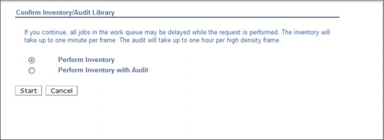
Figure 9-124 TS3500 Tape Library inventory message
|
Important: As stated on the confirmation window (Figure 9-124), if you continue, all jobs in the work queue might be delayed while the request is performed. The inventory will take up to one minute per frame. The audit will take up to one hour per high-density frame.
|
9.4.6 Inventory upload
See the “Physical Volume Ranges page” on page 503 for information about an inventory upload. See also Figure 9-59 on page 503.
Click Inventory Upload to synchronize the physical cartridge inventory from the attached tape library with the TS7740 Virtualization Engine database.
|
Note: Perform the Inventory Upload from the TS3500 Tape Library to all TS7740 Virtualization Engines attached to that tape library whenever a library door is closed, manual inventory or Inventory with Audit is performed, or TS7740 is varied online from an offline state.
|
9.5 Tape cartridge management
Most of the tape management operations are described in 9.1, “User interfaces” on page 414.
Information about tape cartridges and labels, inserting and ejecting stacked volumes, and exception conditions is explained.
9.5.1 3592 tape cartridges and labels
The data tape cartridge used in a 3592 contains the following items (numbers correspond to Figure 9-125 on page 635):
•A single reel of magnetic tape
•Leader pin (1)
•Clutch mechanism (2)
•Cartridge write-protect mechanism (3)
•Internal cartridge memory (CM)
Figure 9-125 on page 635 shows a J-type data cartridge.
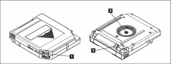
Figure 9-125 Tape cartridge
See Table 4-1 on page 130 and Table 4-2 on page 131 for a complete list of drives, models, and compatible cartridge types.
Labels
The cartridges use a media label to describe the cartridge type, as shown in Figure 9-126 (JA example). In tape libraries, the library vision system identifies the types of cartridges during an inventory operation. The vision system reads a volume serial number (VOLSER), which appears on the label on the edge of the cartridge. The VOLSER contains from one to six characters, which are left-aligned on the label. If fewer than six characters are used, spaces are added. The media type is indicated by the seventh and eighth characters.

Figure 9-126 Cartridge label
9.5.2 Manual insertion of stacked cartridges
There are two methods for physically inserting a stacked volume into the TS3500 Tape Library:
•Opening the library doors and directly inserting the tape into the tape library storage cells
•Using the tape library I/O station
Inserting directly into storage cells
Open the front door of a frame and bulk load the cartridges directly into empty storage slots. This method takes the TS3500 Tape Library out of operation. Therefore, use it only to add or remove large quantities of tape cartridges.
The TS3500 Tape Library Cartridge Assignment Policy (CAP) defines which volumes are assigned to which logical library partition. If the VOLSER is included in the TS7740 Virtualization Engine’s range, it will be assigned to the associated TS3500 Tape Library logical library partition.
After the doors on the library are closed and the tape library has performed inventory, the upload of the inventory to the TS7700 Virtualization Engine will be processed before the TS3500 Tape Library reaches the READY state. The TS7700 Virtualization Engine updates its database accordingly.
|
Tips:
•The inventory is performed only on the frame where the door is opened and not on the frames to either side. If you insert cartridges into a frame adjacent to the frame that you opened, you must perform a manual inventory of the adjacent frame using the operator window on the TS3500 Tape Library itself.
•For a TS7740 Virtualization Engine, it is important to note that the external cartridge bar code label and the internal VOLID label match or, as is the case for a new cartridge, the internal VOLID label is blank. If the external label and the internal label do not meet this criteria, the cartridge will be rejected.
|
Inserting cartridges using the I/O station
The TS3500 Tape Library detects volumes in the I/O station, and then moves the volumes to empty cells. The TS3500 Tape Library CAP defines which volumes are assigned to which logical library. If the VOLSER is included in the System z range, it will be assigned to the TS3500 Tape Library logical library partition. If any VOLSER is not in a range defined by the CAP, identify a System z logical library as the destination by using the Insert Notification process.
Under certain conditions, cartridges are not assigned to a logical library partition in the TS3500 Tape Library. With TS7700 Virtualization Engine R1.5 and later, the TS3500 must have a dedicated logical partition for the cluster. Therefore, in a library with more than one partition, be sure that the Cartridge Assignment Policy is kept up-to-date with the cartridge volume range (or ranges) in use. This minimizes conflicts by ensuring that the cartridge is accessible only by the intended partition.
|
Consideration: Unassigned cartridges can exist in the TS3500 Tape Library, but “unassigned” cartridges can have different meanings and need different actions. See IBM System Storage TS3500 Tape Library with ALMS Operator Guide, GA32-0594, for more information.
|
9.5.3 Exception conditions
On a physical library, important exception conditions include Out of Physical Volumes and Above Threshold Warning.
Out of Physical Volumes
When a distributed library associated with a cluster runs out of scratch stacked physical volumes, operations of the TS7740 Virtualization Engine are affected.
As part of normal processing, data is copied from cache to physical volumes in a primary pool managed by the Virtualization Engine. A copy might also be made to a physical volume in a secondary pool if the dual copy function is specified using Management Class. Empty physical volumes are needed in a pool or, if a pool is enabled for borrowing, in the common scratch pool, for operations to continue. If a pool runs out of empty physical volumes and there are no volumes that can be borrowed, or borrowing is not enabled, operations that might use that pool on the distributed library must be suspended. If one or more pools run out of empty physical volumes, the distributed library enters the Out of Physical Scratch state. The Out of Physical Scratch state is reported to all hosts attached to the cluster associated with the distributed library and, if included in a grid configuration, to the other clusters in the grid. The following MVS console message is generated to inform you of this condition:
CBR3789E VTS library library-name is out of empty stacked volumes.
Library-name is the name of the distributed library in the state. The CBR3789E message will remain on the MVS console until empty physical volumes have been added to the library, or the pool that is out has been enabled to borrow from the common scratch pool and there are empty physical volumes to borrow. Intervention-required conditions are also generated for the out-of-empty-stacked-volume state and for the pool that is out of empty physical volumes.
If the option to send intervention conditions to attached hosts is set on the TS7700 Virtualization Engine that is associated with the distributed library, the following console messages are also generated to provide specifics about the pool that is out of empty physical volumes:
CBR3750I Message from library library-name: OP0138 The Common Scratch Pool (Pool 00) is out of empty media volumes.
CBR3750I Message from library library-name: OP0139 Storage pool xx is out of scratch volumes.
The OP0138 message indicates the media type that is out in the common scratch pool. These messages do not remain on the MVS console. The intervention conditions can be viewed through the TS7700 Virtualization Engine MI.
If the TS7740 Virtualization Engine is in a grid configuration, and if its associated distributed library enters the out-of-empty-stacked-volume state, operations are affected in other ways:
•All copy operations are immediately suspended in the cluster (regardless of which pool has become empty).
•If the cluster has a Copy Consistency Point of RUN, the grid enters the Immediate Mode Copy Operations Deferred state, and an MVS console message is generated:
CBR3787E One or more immediate mode copy operations deferred in library
library-name.
•If another cluster attempts to copy a logical volume that is not resident in the cache, the copy attempt fails.
•The grid prefers clusters that are not in the out-of-empty-stacked-volume state in choosing a TVC cluster, but the gird can still select a remote TVC whose cluster is in that state. If the data needed is not in the remote cluster’s TVC, the recall of the data will fail. If data is being written to the remote cluster’s TVC, the writes will be allowed, but because there might not be any empty physical volumes available to copy the data to, the cache might become full of data that cannot be copied and all host I/O using that cluster’s TVC will become throttled to prevent a cache overrun.
|
Consideration: Because having a distributed library in the out-of-empty-stacked-volume state affects operations in a TS7740 Virtualization Engine, avoid this situation if at all possible.
|
Monitor the number of empty stacked volumes in a library. If the library is close to running out of a physical volume media type, take action to either expedite the reclamation of physical stacked volumes or add additional ones. You can use the Bulk Volume Information Retrieval (BVIR) function to obtain the physical media counts for each library. The information obtained includes the empty physical volume counts by media type for the common scratch pool and each defined pool.
Above Threshold Warning state
The TS7740 Virtualization Engine enters the Above Threshold Warning state when the amount of data to copy exceeds the threshold for the installed cache capacity for five consecutive sample periods (the amount of data to copy is sampled every 30 seconds). The TS7740 Virtualization Engine leaves the Above Threshold Warning state when the amount of data to premigrate is below the threshold capacity for 30 consecutive sample periods. The consecutive sampling criteria is to prevent excessive messages from being created. This state produces the following message:
CBR3750I Message from library library-name:OP0160 Above threshold for uncopied data in cache, throttling possible
9.6 Managing logical volumes
In addition to the tasks described in Chapter 5, “Hardware implementation” on page 189 and in 9.2, “TS7700 Virtualization Engine Management Interface” on page 419, a few more management tasks and considerations for logical volumes are covered.
9.6.1 Scratch volume recovery for logical volumes
The advantage of this method of managing data is that if you determine that a volume was mistakenly returned to scratch, you only have to return the volume to private status to recover from the mistake, as long as you have not reused the volume or the “grace period” has not expired. The method to recover depends on the tape management system used. In general, change the status volumes from scratch to private and change the expiration date by adding at least one week to prevent the Tape Management System from returning the volume to scratch during the next few days. For example, for DFSMSrmm, the following command will return the volume to private status and increase its retention period, including communicating the change to the TS7700 Virtualization Engine (see z/OS DFSMSrmm Guide and Reference, SC26-7404, for details about the command):
RMM CHANGEVOLUME yyyyyy STATUS(USER) RETPD(days) OWNER(userid)
In the command, yyyyyy is the VOLSER.
9.6.2 Ejecting logical volumes
Logical volumes are not physical entities that can be individually removed from the library. They reside on stacked volumes with many other logical volumes.
Because of the permanent nature of the EJECT, the TS7700 Virtualization Engine only allows you to EJECT a logical volume that is in either the INSERT or SCRATCH category. If a logical volume is in any other status, the EJECT fails. If you eject a scratch volume, you will not be able to recover the data on that logical volume.
|
Tip: Logical volumes that are in the error category (000E) can be moved back to the scratch category by using ISMF to move them from Scratch to Scratch category.
|
Ejecting large numbers of logical volumes can have a performance impact on the host and the library.
Tapes that are in INSERT status can be ejected by the resetting of the return code through the CBRUXENT exit. This exit is usually provided by your tape management system vendor. Another way to EJECT cartridges in the INSERT category is by using the MI. For more information, see “Delete Virtual Volumes window” on page 479.
After the tape is in SCRATCH status, follow the procedure for EJECT processing based on whether your environment is system-managed tape or Basic Tape Library Support (BTLS). You also must follow the procedure that is specified by your tape management system vendor. For DFSMSrmm, issue the RMM CHANGEVOLUME volser EJECT command.
If your tape management system vendor does not specify how to do this, you can use one of the following commands:
•z/OS command LIBRARY EJECT,volser
•IDCAMS command LIBRARY EJECT,volser (for BTLS)
•ISMF EJECT line operator for the tape volume
The eject process fails if the tape is in another status or category. For libraries managed under DFSMS system-managed tape, the system command LIBRARY EJECT,volser issued to a logical volume in PRIVATE status fails with this message:
CBR3726I Function incompatible error code 6 from library <library-name> for volume <volser>
|
Clarification: In a DFSMS system-managed tape environment, if you try to eject a logical volume and get this error, OAM notifies the tape management system. This is done through the OAM eject exit CBRUXEJC command before the eject request is sent to the tape library. The Integrated Library Manager will eventually fail the eject, but the tape management system has already marked the volume as ejected. Before APAR OW54054, there was no notification back that the eject failed.
Failed Eject Notification was added to OAM with APAR OW54054 and is currently in all supported releases of DFSMS. Any tape management system supporting this notification can use this function.
|
If your tape management system is DFSMSrmm, you can use the following commands to clean up the Removable Media Management (RMM) control data set (CDS) for failed logical volume ejects and to resynchronize the TCDB and RMM CDS:
RMM SEARCHVOLUME VOL(*) OWN(*) LIM(*) INTRANSIT(Y) LOCATION(vts) -
CLIST('RMM CHANGEVOLUME ',' LOC(vts)')
EXEC EXEC.RMM
CLIST('RMM CHANGEVOLUME ',' LOC(vts)')
EXEC EXEC.RMM
The first RMM command asks for a list of volumes that RMM thinks it has ejected and writes a record for each in a sequential data set called prefix.EXEC.RMM.CLIST. The CLIST then checks that the volume is really still resident in the VTS library and, if so, it corrects the RMM CDS.
|
Tip: Limiting the number of outstanding ejects to a few thousand total per system will limit exposure to performance problems.
|
Be aware of the following considerations when ejecting large numbers of logical volumes. OAM helps mitigate this situation by restricting the number of ejects sent to each library at a given time and manages all the outstanding requests. This management requires storage on the host, and a large number of ejects can force OAM to reserve large amounts of storage. Additionally, there is a restriction on the number of eject requests on the device service’s queue. All of these conditions can have an impact on the host’s performance.
Therefore, a good limit for the number of outstanding eject requests is no more than two thousand per system. Additional ejects can be initiated when others complete. For additional information, see APAR OW42068. The following commands can be used on the System z hosts to list the outstanding and the active requests:
F OAM,QUERY,WAITING,SUM,ALL
F OAM,QUERY,ACTIVE,SUM,ALL
9.7 Messages and displays
The enhanced message support and relevant messages related to the TS7700 Virtualization Engine are described.
9.7.1 Console name message routing
Today, with console name message routing support, many of the library-specific messages are only issued to the specified library console (if defined) and not to the specified routing codes.
Although this is not specific to a TS7700 Virtualization Engine, the following critical, action-related messages are now issued by using the specified library console and routing codes, providing maximum visibility:
•CBR3759E Library x safety enclosure interlock open.
•CBR3764E Library x all storage cells full.
•CBR3765E No cleaner volumes available in library x.
•CBR3753E All convenience output stations in library x are full.
•CBR3754E High capacity output station in library x is full.
•CBR3755E {Input|Output} door open in library x.
•CBR3660A Enter {list of media inserts} scratch volumes into x.
9.7.2 Alert setting messages
The SETTING function provides a new set of messages. These messages are described in 9.3.3, “Host Console Request function” on page 602.
The message format is shown:
CBR3750I Message from library lib-id: ALxxxx message description
|
More information: For the latest information about ALxxxx messages and all other messages related to CBR3750I, see the IBM Virtualization Engine TS7700 Series Operator Informational Messages white paper, which is available at the following address:
|
9.7.3 Grid messages
Some of the TS7700 Virtualization Engine grid-specific messages that you might see are listed. For a complete and current list, see the appropriate volume of z/OS MVS System Messages.
Incompatibility error message
In an incompatible function error, you might see the message CBR3726I:
CBR3726I Function incompatible error code error-code from library library-name for volume volser.
In this message, an error has occurred during the processing of volume volser in library library-name. The library returned a unit check with an error code error-code, which indicates that an incompatible function has been requested. A command has been issued that requests an operation that is understood by the subsystem microcode, but cannot be performed because of one of the following errors:
X'00': The function requested is not supported by the subsystem to which the order was issued.
X'01': Library attachment facility not installed and allowed.
X'02': Not currently used.
X'03': High capacity input/output facility is not configured.
X'04': Reserved.
X'05': Volume requested to be mounted is not compatible with the device allocated.
X'06': The logical volume can only be ejected if it is in the insert category and has a mount count of zero, or it is assigned to a category that has the fast-ready attribute set.
X'07': There is no pending import or export operation to cancel.
X'08': There are not enough (four are needed) physical drives available to initiate the import or export operation.
X'09': X'0C' Reserved.
X'0D': The Peer-to-Peer VTS subsystem is either in service preparation mode, or in Service mode, or has an unavailable component within the subsystem such as an unavailable distributed library. Audit, eject, or entry-related commands are not being accepted at this time.
X'0E': The Peer-to-Peer VTS subsystem already has one thousand eject requests queued and is not accepting any more eject requests at this time.
X'0F': An inappropriate library function was issued to the Peer-to-Peer VTS subsystem.
X'10': The VTC in the Peer-to-Peer VTS subsystem or the distributed library in a TS7700 grid configuration that the command was issued to is in read-only or write-protect mode and is not accepting requests that change the category or attributes of a volume. This mode of operation is provided to support disaster recovery operations in a configuration where the configuration is split between two physical sites.
X'12': The volume specified has a non-zero expire time associated with it. A volume in this state cannot be mounted, moved, or have its attributes modified until the expire time has elapsed.
X'30': The TS7700 cluster that the command was received on does not have an available path to the cluster that currently owns the volume and ownership takeover is not enabled.
X'31': A non-recoverable internal microcode error was detected by the TS7700 Virtualization Engine.
X'32': There is more than one valid copy of the specified export list volume in the TS7700 grid configuration.
X'33': An export operation was issued to a TS7700 that is performing a global operation. Global operations include volume inserts, volume deletions through the management interface, damaged volume recovery and disaster recovery. Export operations are not being accepted at this time.
X'36': The Selective Device Access Control function in the TS7700 Virtualization Engine denied the request. The request was issued on a virtual device address that is not included in the access group associated with the logical volume.
X'37': The Selective Device Access Control function in the TS7700 Virtualization Engine failed the request. The access control group associated with the volume is invalid or not defined.
X'38': An export operation was issued to a TS7700 Virtualization Engine, and the export list volume specified is a logical WORM volume. The export list volume cannot be WORM.
9.7.4 Display grid status
The following messages can be issued for the TS7700 Virtualization Engine Grid.
CBR1100I OAM status
This message is issued in response to the following operator command:
DISPLAY SMS,OAM
Example 9-16 shows a sample of the display message text.
Example 9-16 DISPLAY SMS,OAM command
CBR1100I OAM status: 618
TAPE TOT ONL TOT TOT TOT TOT TOT ONL AVL TOTAL
LIB LIB AL VL VCL ML DRV DRV DRV SCRTCH
5 2 0 . 0 2 .... 0 .192 . 192.. 127 46079
There are also 2 VTS distributed libraries defined.
CBRUXCUA processing ENABLED.
CBRUXEJC processing ENABLED.
CBRUXENT processing ENABLED.
CBRUXVNL processing ENABLED.
If any TS7700 Virtualization Engine subsystems are defined to the system, the following status line is displayed, reflecting the number of distributed libraries that are associated with the composite libraries:
There are also numvdl-lib VTS distributed libraries defined.
CBR1110I OAM library status
The CBR1110I message is issued in response to the following command:
DISPLAY SMS,LIBRARY(library-name),DETAIL
Example 9-17 shows the complete message text.
Example 9-17 DISPLAY SMS, LIBRARY command
CBR1110I OAM library status: 334
TAPE LIB DEVICE TOT ONL AVL TOTAL EMPTY SCRTCH ON OP
LIBRARY TYP TYPE DRV DRV DRV SLOTS SLOTS VOLS
HYDRAO VCL 3957-V06 128 128 64 0 0 44365 Y Y
--------------------------------------------------------------------
MEDIA SCRATCH SCRATCH SCRATCH
TYPE COUNT THRESHOLD CATEGORY
MEDIA2 44365 100 . 0002
-------------------------------------------------------------------------------------------------------------
DISTRIBUTED LIBRARIES: HYDRAD
LIBRARY ID: 10001
OPERATIONAL STATE: AUTOMATED
ERROR CATEGORY SCRATCH COUNT: 0
CORRUPTED TOKEN VOLUME COUNT: 0
---------------------------------------------------------------------
|
Clarification: Library type VCL indicates the composite library, as opposed to VDL for the distributed library.
|
CBR1180I OAM tape volume status
This CBR1180I message is issued in response to the following operator command:
DISPLAY SMS,VOLUME(volser)
Example 9-18 lists the complete message text for logical volume q63842.
Example 9-18 DISPLAY SMS,VOLUME command
d sms,vol(q63842)
CBR1180I OAM tape volume status: 937
VOLUME MEDIA STORAGE LIBRARY USE W C SOFTWARE LIBRARY
TYPE GROUP NAME ATR P P ERR STAT CATEGORY
Q63842 MEDIA2 TPHYDPRD GRID03 P N N NOERROR PRIVATE
-------------------------------------------------------------------
RECORDING TECH: 36 TRACK COMPACTION: YES
SPECIAL ATTRIBUTE: NONE ENTER/EJECT DATE: 2010-04-28
CREATION DATE: 2010-04-28 EXPIRATION DATE: 2014-01-22
LAST MOUNTED DATE: 2010-09-10 LAST WRITTEN DATE: 2010-09-10
SHELF LOCATION:
OWNER:
LM SG: TPHYDPRD LM SC: SCVTSPG0 LM MC: MCVTSIM LM DC: DCVTS4G
LM CATEGORY: 000F
-------------------------------------------------------------------
Logical volume.
Volume is cache resident.
Valid copy in each distributed library.
9.7.5 Warning link status degraded messages
With the Dynamic Link Load Balancing function in the TS7700 Virtualization Engine, host console messaging is provided to assist with grid performance problems. Host console messages are issued when the subsystem determines that the GRID links have crossed a preset performance balance threshold.
There are up to four network links from each cluster participating in a GRID configuration. Every five minutes, the Dynamic Link Load Balancing function evaluates the capabilities of each link between the clusters. If performance in one of the links is 60% less than the other, a warning message is displayed at the System Console in the following format:
CBR3796E Grid links degrade in library library_name
When the grid links are unbalanced, use the Host Console Request function STATUS GRIDLINK (see 9.3.3, “Host Console Request function” on page 602) to get additional information that can be useful with problem determination. Identifying which of the two links is being affected can be helpful in resolving the unbalanced condition. Because the TS7700 Virtualization Engine link parameters cannot be changed, you can only investigate the problem from the perspective of the GRID networking equipment or cabling.
A detailed description of the Host Console Request functions and responses is available in the IBM Virtualization Engine TS7700 Series z/OS Host Command Line Request User’s Guide white paper. The most recently published white papers are available at the Techdocs website. Search for TS7700 Virtualization Engine at the following URL:
You can diagnose a Grid network problem by using the Network tools described in “Network Diagnostics panel” on page 587.
When the grid network performance issue is resolved and the links are balanced, a message is presented at the System Console in the following format:
CBR3797E Grid links in library_name are no longer degraded
9.7.6 Warning VTS operation degraded messages
When a VTS is operating in a degraded state, the following message is issued:
CBR3786E VTS operation degraded in library library-name
When the degradation is resolved, you see this message:
CBR3768I VTS operations in library library-name no longer degraded
9.7.7 Warning cache use capacity (TS7720 Virtualization Engine)
For the TS7720 Virtualization Engine, warning and critical cache free space messages are displayed:
CBR3792E Library library-name has entered the limited cache free space warning state.
CBR3794E Library library-name has entered the out of cache resources critical state.
When the cache situation is resolved, the following messages are shown:
CBR3793I Library library-name has left the limited cache free space warning state.
CBR3795I Library library-name has left the out of cache resources critical state.
9.8 Recovery scenarios
The potential recovery scenarios you might have to perform are described. You are notified about most of the errors that require operator attention through a Host Notification, which is enabled from the Events page of the MI. Check Figure 9-127 for a sample of one Event message that needs an operator intervention.

Figure 9-127 Example of an operator intervention
9.8.1 Hardware conditions
The potential hardware failure scenarios are described. The main source available for reference about the operational or recovery procedures is the IBM Virtualization Engine TS7700 Customer Information Center v3.0.0.0. The TS7700 Customer Information Center is available directly from the TS7700 MI by clicking the question mark (?) symbol in the upper-right corner of the top bar of the MI. See Figure 9-128 for reference.

Figure 9-128 Invoking TS7700 Customer Information Center
IBM 3592 Tape Drive failure (TS7740 Virtualization Engine with library attachment only)
When the TS7700 Virtualization Engine determines that one of its tape drives is not operating correctly and requires service (due to read/write errors, fibre interface, or another hardware-related reason), the drive is marked offline and an IBM SSR must be engaged. The following intervention- required message is displayed on the Library Manager Console:
CBR3750I MESSAGE FROM LIBRARY lib: Device xxx made unavailable by a VTS. (VTS z)
Operation of the TS7700 Virtualization Engine continues with a reduced number of drives until the repair action on the drive is complete. To recover, the IBM SSR repairs the failed tape drive and makes it available for the TS7700 Virtualization Engine to use it again.
Power failure
User data is protected in a power failure, because it is stored on the TVC. Any host jobs reading or writing to virtual tapes will fail as they fail with a real IBM 3490E, and they will need to be restarted after the TS7700 Virtualization Engine is available again. When power is restored and stable, the TS7700 Virtualization Engine must be powered up manually. The TS7700 Virtualization Engine will recover access to the TVC using information available from the TS7700 Virtualization Engine database and logs.
TS7700 Virtualization Engine Tape Volume Cache errors
Eventually, one disk drive module (DDM) or another component might fail in the TS7700 TVC. In this situation, the host will be notified by the TS7700 and the operator will see the HYDIN0571E “Disk operation in the cache is degraded” message. Also, the MI will show the Health Status bar (lower-right corner in Figure 9-128 on page 645) in yellow to warn of a degraded resource in the subsystem. A degraded TVC needs an IBM SSR engagement. The TS7700 Virtualization Engine will continue to operate normally during the intervention.
Accessor failure and manual mode (TS7740 Virtualization Engine with Tape Library attachment only)
If the TS3500 Tape Library does not have the dual accessors installed, failure of the accessor results in the library being unable to automatically mount physical volumes. If TS3500 Tape Library dual accessors are installed, the second accessor takes over. Then, you can call your IBM SSR to repair the failed accessor.
Gripper failure (TS7740 Virtualization Engine only with Tape Library attachment only)
The TS3500 Tape Library has dual grippers. If a gripper fails, library operations continue with the other one. While the gripper is being repaired, the accessor is not available until the repair is complete. If the dual accessors are installed, the second accessor is used until the gripper is repaired. For detailed information about operating the TS3500 Tape Library, see IBM System Storage TS3500 Tape Library with ALMS Operator Guide, GA32-0594.
Out of stacked volumes (TS7740 Virtualization Engine with Tape Library attachment only)
If the tape library runs out of stacked volumes, copying to the 3592 Tape Drives will fail, and an intervention-required message is sent to the host and the TS7700 Virtualization Engine MI. All further logical mount requests are delayed by the Library Manager until more stacked volumes are added to the TS3500 Tape Library connected to the TS7740 Virtualization Engine. To recover, insert more stacked volumes. Copy processing can then continue.
Damaged cartridge pin
The 3592 has a metal pin that is grabbed by the feeding mechanism in the 3592 tape drive to load the tape onto the take-up spool inside the drive. If this pin gets dislodged or damaged, follow the instructions in IBM TotalStorage Enterprise Tape System 3592 Operators Guide, GA32-0465, to correct the problem.
|
Important: Repairing a 3592 tape must only be done for data recovery. After the data has been moved to a new volume, replace the repaired cartridge.
|
Broken tape
If a 3592 tape cartridge is physically damaged and unusable (the tape is crushed, or the media is physically broken, for example), the TS7740 Virtualization Engine cannot recover the contents configured as a stand-alone cluster. If this TS7740 is part of a grid, the damaged tape contents (active logical volumes) will be retrieved from other clusters, and the TS7740 cluster will have those logical volumes brought in automatically (as long as those logical volumes had another valid copy within the grid). Otherwise, this is the same for any tape drive media cartridges. You can make a list of logical volumes that are in that stacked volume, and check with your IBM SSR to learn whether IBM services are available to attempt data recovery from a broken tape.
Logical mount failure
When a mount request is received for a logical volume, the TS7700 Virtualization Engine determines whether the mount request can be satisfied and, if so, tells the host that it will process the request. Unless an error condition is encountered in the attempt to mount the logical volume, the mount operation completes and the host is notified that the mount was successful. With the TS7700 Virtualization Engine, the way that a mount error condition is handled is different than with the prior generations of VTS. With the prior generation of VTS, the VTS always indicated to the host that the mount completed even if a problem had occurred. When the first I/O command was issued, the VTS then fails that I/O because of the error. This results in a failure of the job without the opportunity to try to correct the problem and retry the mount.
With the TS7700 Virtualization Engine subsystem, if an error condition is encountered during the execution of the mount, instead of indicating that the mount was successful, the TS7700 Virtualization Engine returns completion and reason codes to the host indicating that a problem was encountered. With DFSMS, the logical mount failure completion code results in the console messages shown in Example 9-19.
Example 9-19 Unsuccessful mount completion and reason codes
CBR4195I LACS RETRY POSSIBLE FOR JOB job-name
CBR4171I MOUNT FAILED. LVOL=logical-volser, LIB=library-name, PVOL=physical-volser, RSN=reason-code
...
CBR4196D JOB job-name, DRIVE device-number, VOLSER volser, ERROR CODE error-code. REPLY ’R’ TO RETRY OR ’C’ TO CANCEL
Reason codes provide information about the condition that caused the mount to fail:
•For example, we look at CBR4171I. Reason codes are documented in the Customer Information Center. As an exercise, assume RSN=32. In the information center, we see this reason code:
Reason code x’32’: Local cluster recall failed; the stacked volume is unavailable.
•CBR4196D: Error code shows in the format 14xxIT:
– 14 is the permanent error return code
– xx is 01 if the function was a mount request or 03 if the function was a wait request.
– IT is the permanent error reason code. The recovery action to be taken for each CODE.
– In our example, it is possible to have a value of 140194 for the error code, which means xx=01: Mount request failed.
•IT=94: Logical volume mount failed. An error was encountered during the execution of the mount request for the logical volume. The reason code that is associated with the failure is documented in CBR4171I. The first book title includes the acronyms for message IDs but the acronyms are not defined in the book: For CBR messages, see z/OS MVS System Messages, Vol 4 (CBD-DMO), SA38-0671, for an explanation of the reason code and for specific actions that you might need to take to correct the failure. See z/OS DFSMSdfp Diagnosis, SC23-6863, for OAM return and reason codes. Take the necessary corrective action and reply 'R' to retry. Otherwise, reply 'C' to cancel.
|
Tip: Always see the appropriate documentation (TS7700 Customer Information Center and MVS System Messages) for the meaning of the messages and the applicable recovery actions.
|
Orphaned logical volume
This situation occurs when the TS7700 Virtualization Engine database has a reference to a logical volume but no reference to its physical location. This can result from hardware or internal software errors. If you run into an orphaned logical volume message, contact your IBM SSR.
Internal-external label mismatch
If a label mismatch occurs, the stacked volume is ejected to the Convenience Input/Output Station and the intervention-required condition is posted at the TS7740 Virtualization Engine MI and sent to the host console (Example 9-20).
Example 9-20 Label mismatch
CBR3750I MESSAGE FROM LIBRARY lib: A stacked volume has a label mismatch and has been ejected to the Convenience Input/Output Station.
Internal: xxxxxx, External: yyyyyy
Internal: xxxxxx, External: yyyyyy
The host is notified that intervention-required conditions exist. Investigate the reason for the mismatch. If possible, relabel the volume to use it again.
Failure during reclamation
If there is a failure during the reclamation process, the process is managed by the TS7740 Virtualization Engine microcode. No user action is needed because recovery is managed internally.
Excessive temporary errors on stacked volume
When a stacked volume is determined to have an excessive number of temporary data errors, to reduce the possibility of a permanent data error, the stacked volume is placed in read-only status.
9.8.2 TS7700 Virtualization Engine software failure
If a problem develops with the TS7700 Virtualization Engine software, the TS7700 Virtualization Engine issues an intervention-required message to the TS7700 Virtualization Engine MI and host console, and attempts to recover. In the worst case, this can involve a reboot of the TS7700 Virtualization Engine itself. If the problem persists, you need to contact your IBM SSR. The intervention-required message shown in Example 9-21 is sent to the host console.
Example 9-21 VTS software failure
CBR3750I MESSAGE FROM LIBRARY lib: Virtual Tape System z has a CHECK-1 (xxxx) failure
The TS7700 Virtualization Engine internal recovery procedures handle this situation and restart the TS7700 Virtualization Engine. See Chapter 11, “Disaster recovery” on page 765 for more details.
9.9 TS7720 Virtualization Engine operational considerations
With a TS7720 Virtualization Engine configuration, certain operations are unavailable or disabled on the MI. These functions are only applicable to the TS7740 cluster. However, some settings are exclusive for the TS7720, such as the TS7720 temporary cache removal policy. The following examples show the basic visual differences between the TS7720 and TS7740 MI in relation to health monitoring.
9.9.1 Management interface for TS7720
Using the TS7700 Virtualization Engine MI to operate the TS7720 Virtualization Engine is described.
Monitoring the health with TS7720
Figure 9-129 on page 650 shows you where the Health Status bar is displayed in a TS7720 Virtualization Engine configuration.
The TS7720 Virtualization Engine on the left is configured with an expansion frame. Compare that with the illustration of a TS7720 Virtualization Engine with only the base frame on the right.

Figure 9-129 TS7720 Virtualization Engine MI health and monitoring options
You can get details about the health state of each component of the TS7720 or TS7740 by hovering the mouse over the picture that represents your cluster. Also, you can look at the components in the back of the frame by clicking the blue circular arrow near the lower-right corner of the frame. This arrow turns the picture around, showing the back side. Again, hover the mouse over the components for the health details of those components.
Compare Figure 9-129 with Figure 9-130 on page 651, which shows a TS7740 Virtualization Engine.
Figure 9-130 shows the TS7740 MI. A TS3500 Tape Library icon is displayed for the TS7740 Virtualization Engine. Compare it with Figure 9-129 on page 650 (TS7720 clusters, disk-only). By hovering the mouse over the TS3500 icon, you can see the tape library and tape drive health information.

Figure 9-130 TS7740 Virtualization Engine MI
For the remaining possible options, see 9.2, “TS7700 Virtualization Engine Management Interface” on page 419.
..................Content has been hidden....................
You can't read the all page of ebook, please click here login for view all page.