

Architecture, components, and functional characteristics
This chapter provides a description of the architecture of the IBM Virtualization Engine TS7700. The description includes general virtualization concepts, new concepts, and functions introduced with TS7700 Virtualization Engine R3.0. In addition, hardware components and configuration scenarios for high-availability solutions are addressed.
All characteristics that are valid for both stand-alone cluster and multicluster grids are explained. The functions that are only valid for grids and all deviations from a stand-alone cluster environment are explained.
The following topics are described:
•Terms and expressions used to describe the TS7700 Virtualization Engine
•Architecture of the TS7700 Virtualization Engine
•Underlying concepts of tape virtualization within the TS7700 Virtualization Engine
•Hardware components for TS7700 Virtualization Engine Release 3.0, including new server and adapter capabilities
•Attachment of the IBM Virtualization Engine TS7740 to an IBM System Storage® TS3500 Tape Library and tape drive support
•Multicluster grid providing support for hybrid-cluster, 5-cluster, and 6-cluster TS7700 grid configurations
•Cluster families
•User security and user access enhancements
•Grid network support for (two or four) copper or shortwave (SW) fibre 1-Gbps links or two long-wave (LW) 10-Gbps links
•Immediate copy failure reporting on Rewind Unload response
•Functional characteristics of the TS7700 Virtualization Engine
•Synchronous mode copy as an additional copy policy
•Logical Write Once Read Many (WORM) support
•Enhanced cache removal policies for grids containing one or more TS7720 clusters
•Selective write protect for disaster recovery (DR) testing
•Device allocation assistance (DAA)
•Scratch allocation assistance (SAA)
•Selective device access control (SDAC)
•On-demand support of up to 4,000,000 logical volumes
This chapter includes the following topics:
•Stand-alone cluster: Components, functionality, and features
•Multicluster grid: Components, functionality, and features
•Hardware components
2.1 TS7700 Virtualization Engine architecture
The architectural design of the TS7700 Virtualization Engine and its potential capabilities are addressed. A short description of the Virtual Tape Server (VTS) architecture is included to help you understand the differences.
Every time that we use the term “TS7700,” both TS7720 and TS7740 are referenced. There might be small differences, such as the amount of storage or the performance characteristics, but the underlying architecture, capability, and functionality are the same. If a function or capability is only available for either the TS7720 or the TS7740, the specific product term is used. If a function or feature works slightly differently between the two models, this also is described.
2.1.1 Monolithic design of a Virtual Tape Server
The 3494 Virtual Tape Server (VTS) performed all functions within a single IBM System p® server. The VTS also serves as the RAID disk controller. The RAID system is tightly integrated into the system. To expand the capabilities and functionality, the expansions must fit within the capabilities of the System p server. Because code components are tightly integrated with one another, implementing new functions affects large amounts of code. In addition, the system must be upgraded or extended as a whole because of the tight integration of its components.
All these concerns have been addressed in the architectural design of the TS7700 Virtualization Engine.
2.1.2 Modular design of the TS7700 Virtualization Engine
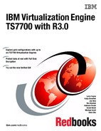
The modular design of the TS7700 Virtualization Engine separates the functionality of the system into smaller components. These components have well-defined functions connected by open interfaces. The platform allows components to be scaled up from a small configuration to a large one. This provides the capability to grow the solution to meet business objectives.
The TS7700 Virtualization Engine is built on a distributed node architecture. This architecture consists of nodes, clusters, and grid configurations. The elements communicate with each other through standard-based interfaces. In the current implementation, a virtualization node (vNode) and hierarchical data storage management node (hNode) are combined into a general node (gNode), running on a single System p server. The Tape Volume Cache (TVC) module is a high-performance a RAID disk controller or controllers. The TVC has redundant components for high availability (HA) and attaches through Fibre Channel (FC) to the Virtualization Engine.
A TS7700 Virtualization Engine and the previous VTS design are shown in Figure 2-1 on page 18.
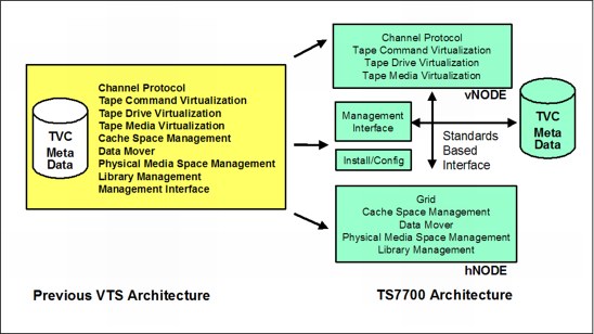
Figure 2-1 TS7700 virtualization design compared to a VTS design
Nodes
Nodes are the most basic components in the TS7700 Virtualization Engine architecture. A node has a separate name depending on the role associated with it. There are three types of nodes:
•Virtualization nodes
•Hierarchical data storage management nodes
•General nodes
Virtualization node (vNode)
A vNode is a code stack that presents the virtual image of a library and drives to a host system. When the TS7700 Virtualization Engine is attached as a virtual tape library, the vNode receives the tape drive and library requests from the host. The vNode then processes them as real devices process them. It then translates the tape requests through a virtual drive and uses a file in the cache subsystem to represent the virtual tape image. After the logical volume is created or altered by the host system through a vNode, it resides in disk cache.
Hierarchical data storage management node (hNode)
An hNode is a code stack that performs management of all logical volumes residing in disk cache or physical tape. This management occurs after the logical volumes are created or altered by the host system through a vNode. The hNode is the only node that is aware of physical tape resources and the relationships between the logical volumes and physical volumes. It is also responsible for any replication of logical volumes and their attributes between clusters. An hNode uses standardized interfaces (TCP/IP) to communicate with external components.
General node (gNode)
A gNode can be considered a vNode and an hNode sharing the same physical controller. The current implementation of the TS7700 Virtualization Engine runs on a gNode. The engine has both a vNode and hNode combined within an IBM System POWER7 processor-based server. Figure 2-2 on page 19 shows a relationship between nodes.

Figure 2-2 Node architecture
Cluster
The TS7700 Virtualization Engine cluster combines the TS7700 Virtualization Engine server with one or more external (from the server’s perspective) disk subsystems. This subsystem is the TS7700 Virtualization Engine cache controller. This architecture permits expansion of disk cache capacity. It also allows the addition of vNodes or hNodes in future offerings to enhance the capabilities of the Tape Virtualization System.
Figure 2-3 shows the TS7700 Virtualization Engine configured as a cluster.
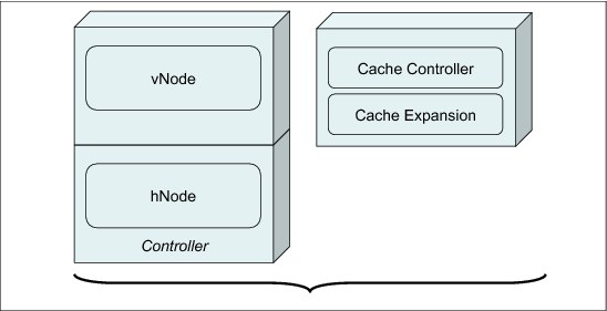
Figure 2-3 TS7700 Virtualization Engine cluster
A TS7700 Virtualization Engine cluster provides Fibre Channel connection (FICON) host attachment and 256 virtual tape devices. The TS7740 Virtualization Engine cluster also includes the assigned TS3500 Tape Library partition, fiber switches, and tape drives. The TS7720 Virtualization Engine can include one or more optional cache expansion frames.
Figure 2-4 on page 20 shows the components of a TS7740 Virtualization Engine cluster.
Figure 2-4 TS7740 Virtualization Engine cluster components
The TS7700 Cache Controller consists of a redundant array of independent disks (RAID) controller and associated disk storage media. These items act as cache storage for data. The R3.0 CS9/CX9 contain 12 Serial Advanced Technology Attachment (SATA) 3.5-inch disks. The R3.0 CC9/CX9 contain 24 or 22 2.5-inch serial-attached SCSI (SAS) disks. The capacity of each disk drive module (DDM) depends on your configuration. The TS7700 Cache Drawer acts as an expansion unit for the TS7700 Cache Controller. The drawer and controller collectively are called the TS7700 Cache. The amount of cache available per TS7700 Cache Drawer depends on your configuration.
The TS7740 Virtualization Engine Cache provides a RAID 5 (up to CC8) and a RAID 6 (since CC9) protected virtual volume storage to temporarily hold data before writing it to physical tape. It then caches the data to allow fast retrieval from disk.
The TS7720 use RAID 6 protection.
2.1.3 Peer-to-peer VTS design
In a 3494 peer-to-peer (PTP) VTS, you needed external Virtual Tape Controller (VTC) hardware to present the components as a single library to the host. The VTCs were connected to the host through IBM ESCON® or FICON. Each VTC was connected to both VTSs. Only two VTSs were able to be connected to a peer-to-peer environment. The new architecture of grid allows you to have more clusters acting as one entity, and also allows the introduction of many new features and functions.
2.1.4 Principles of grid design
The TS7700 Virtualization Engine R3.0 grid configuration is a series of two, three, four, five, or six clusters. These clusters are connected by grid links to each other by a grid network to constitute resilient DR and highly available solutions.
|
Note: Five-cluster grid and six-cluster grid configurations are available with a request for price quotation (RPQ).
|
A grid configuration looks like a single tape library, including tape drives to the attached hosts. Whether it is a stand-alone cluster or multicluster configuration, the entire subsystem appears as a single tape library to the attached hosts.
Logical volumes (data and tokens) are replicated across the grid links, depending on your TS7700 grids definitions. When or if a replication of data occurs is controlled through several parameters, such as Copy Consistency Points and override policies. Access is independent of where the copy of the logical volumes exists. A logical volume can be mounted through any virtual device in any cluster in the grid.
In general, any data initially created or replicated between clusters is accessible through any available cluster in a grid configuration. This concept ensures that data can still be accessed even if a cluster becomes unavailable.
A grid can contain all TS7720 clusters, all TS7740 clusters, or a mix of the two, which is referred to as a hybrid grid.
The term multicluster grid is used for a grid with two or more clusters.
For a detailed description, see 2.3, “Multicluster grid configurations: Components, functionality, and features” on page 49.
2.1.5 Management of the TS7700
The management of the TS7700 is based on eight key components:
•TS7700 Management Interface
•TS3500 web interface
•Advanced (outboard) policy management
•Data Facility Storage Management Subsystem (DFSMS) integration with the TS7700 to provide the storage management subsystem (SMS) constructs’ names for policy management
•Host commands to control the TS7700
•Messages for automated alerting and operations
•Tools
•Call home support
TS7700 Management Interface (MI)
The TS7700 MI is used to configure the TS7700, set up outboard policy management behavior, monitor the systems, and many other client-facing management functions.
TS3500 web interface
The TS3500 web interface is used to configure and operate the TS3500 tape library, particularly for the management of physical drives and media.
Advanced (outboard) policy management
Policy management enables you to better manage your logical and stacked volumes through the usage of the SMS construct names. With z/OS and DFSMS, the SMS construct names that are associated with a volume (Storage Class, Storage Group, Management Class, and Data Class) are sent to the library. When a volume is written from load point, the eight-character SMS construct names (as assigned through your automatic class selection (ACS) routines) are passed to the library. At the library’s MI, you can then define policy actions for each construct name, enabling you and the TS7700 to better manage your volumes. For the other System z platforms, constructs can be associated with the volumes, when the volume ranges are defined through the library’s MI.
DFSMS constructs in System z and their equivalents in TS7700
In System z, four DFSMS constructs exist:
•Storage Class
•Storage Group
•Management Class
•Data Class
Each of these constructs is used to determine specific information about the data that has to be stored. All construct names are also presented to the TS7700. They need to have an equivalent definition at the library. You can define these constructs in advance on the TS7700 MI. See 5.3.8, “Defining TS7700 constructs” on page 235.
If constructs are sent to the TS7700 without having predefined constructs on the TS7700, the TS7700 creates the construct with default parameters.
|
Note: Predefine your SMS constructs on the TS7700. The constructs created automatically might not be suitable for your requirements.
|
Storage class in SMS
Storage classes perform three functions. They decide whether data is SMS-managed. They decide the level of performance of a data set. They decide whether you can override SMS and place data on specific volumes.
Storage class in TS7700
The storage class in TS7700 is used to set the cache preferences for the logical volume. This definition is cluster-based.
Storage Group in SMS
Storage Groups are the fundamental concept of DFSMS. DFSMS groups disks together into storage pools, so you allocate by storage pool. Storage pools can also consist of tape volumes. This allows SMS to direct tape allocations to a VTS or automated library. For tape Storage Groups, one or more tape libraries can be associated with them. Connectivity is defined at both the library level and the Storage Group level. If a Storage Group is connected to certain systems, then any libraries associated with that Storage Group must be connected to the same systems. You can direct allocations to a local or remote library or to a specific library by assigning the appropriate Storage Group in the Storage Group ACS routine.
Storage Group in TS7700
The Storage Group in the TS7700 is used to map the logical volume to a physical pool and the primary pool number. This definition is cluster-based.
Management Class in SMS
Management Classes are used to determine backup and migration requirements. When assigned to data sets, Management Classes replace and expand attributes that otherwise are specified on JCL data definition (DD) statements, IDCAMS DEFINE commands, and DFSMShsm commands. A Management Class is a list of data set migration, backup, and retention attribute values. A Management Class also includes object expiration criteria, object backup requirements, and class transition criteria for the management of objects.
Management Class in TS7700
From the TS7700 side, the Management Class is used for functions, such as Copy Policy, Selective Dual Copy Pool (depending on the physical pool, this function might be used for Copy Export), Retain Copy Mode, and Scratch Mount Candidate for Scratch Allocation assistance. This definition is cluster-based.
DATACLASS in SMS
The DATACLASS construct defines what a file looks like. The DATACLASS ACS routine is always invoked, even if a file is not SMS-managed. A DATACLASS is only ever assigned when a file is created and cannot be changed. A file is described by its data set organization, record format, record length, space allocation, how many volumes it can span, data compaction, media type, and recording information.
DATACLASS in TS7700
DATACLASS in the TS7700 is used for the definition of the virtual volume size and whether it has to be treated as a logical WORM volume. This definition is shared on the grid. If you define it on one cluster, it is propagated in all other clusters in the grid.
Storage Group, Storage Class, and Management Class only affect the local cluster. The DATACLASS is shared grid-wide.
Host commands
Several commands to control and monitor your environment are available. They are described in detail in Chapter 5, “Hardware implementation” on page 189, Chapter 8, “Migration” on page 371, Chapter 9, “Operation” on page 413, and Appendix H, “Library Manager volume categories” on page 953.
These major commands are available:
D SMS,LIB Display library information for composite and distributed libraries
D SMS,VOLUME Display volume information for logical volumes
LI REQ The LIBRARY REQUEST command, also known as the Host Console Request function, is initiated from a z/OS host system to a TS7700 composite library or a specific distributed TS7700 library within a grid. Use the LIBRARY REQUEST command to request information related to the current operational state of the TS7700 Virtualization Engine, its logical and physical volumes, and its physical resources. The command can also be used to perform outboard operations at the library, especially setting alerting thresholds. Because all keyword combinations are simply passed to the TS7700 and all responses are text-based, the LIBRARY REQUEST command is a primary means of adding management features with each TS7700 release without requiring host software changes. When settings are changed, the TS7700 behavior can change for all hosts utilizing the TS7700, which you need to consider when changing settings through the LI REQ command. See to the published white paper (http://www-03.ibm.com/support/techdocs/atsmastr.nsf/WebIndex/WP101091).
DS QLIB Use the DEVICE SERVICES QUERY LIBRARY command to display library and device-related information for the composite and distributed libraries.
There is a subtle difference but it is important to understand. A DS QL command may return different data depending on which host it is issued. An LI command returns the same data without regard to the host, as long as both hosts have full accessibility.
Automation handling and messages
Mainly, consider the CBRxxxx messages. For more information, see the following document:
Tools
There are many helpful tools provided for the TS7700. See Chapter 10, “Performance and monitoring” on page 653.
Call Home support
The Call Home function generates a service alert automatically when a problem is detected within the subsystem, such as a problem in the following components:
•Inside the TS7700 components themselves
•In the associated TS3500 library and tape drives
•In the cache disk subsystem
Status information is transmitted to the IBM Support Center for problem evaluation. An IBM service support representative (SSR) can be dispatched to the installation site if maintenance is required. Call Home is part of the service strategy adopted in the TS7700 family. It is also used in a broad range of tape products, including VTS models and tape controllers, such as the 3592-C07.
The Call Home information for the problem is transmitted with the appropriate information to the IBM product support group. This data includes the following information:
•Overall system information, such as system serial number, microcode level, and so on
•Details of the error
•Error logs that can help to resolve the problem
After the Call Home is received by the assigned IBM support group, the associated information is examined and interpreted. Following analyses, an appropriate course of action is defined to resolve the problem. For instance, an IBM SSR might be sent to the site location to take the corrective actions. Or, the problem might be repaired or resolved remotely by the IBM support personnel through a broadband (if available) or telephone connection.
The TS3000 System Console (TSSC) is the subsystem component responsible for placing the service call or Call Home whenever necessary. The call itself can go through a telephone line or can be placed over a broadband connection, if available. The TS3000 System Console is equipped with an internal or external modem, depending on the model.
2.2 Stand-alone cluster: Components, functionality, and features
In general, a stand-alone cluster can either be a TS7720 or a TS7740 with the attached TS3500.
The TS7700 has several internal characteristics for HA (RAID 6 protection, dual power supplies, and so forth). However, a grid configuration is designed for a HA solution and provides the most redundant setup. See Chapter 3, “TS7700 usage considerations” on page 109.
Next, general information is provided about the components, functionality, and features used in a TS7700 environment. The general concepts and information are also in 2.2, “Stand-alone cluster: Components, functionality, and features” on page 25. Only deviations and additional information for multicluster grid are in 2.3, “Multicluster grid configurations: Components, functionality, and features” on page 49.
2.2.1 Views from the Host: Library IDs
All host interaction with tape data in a TS7700 Virtualization Engine is through virtual volumes and virtual tape drives.
You must be able to identify the logical entity that represents the virtual drives and volumes, but also address the single entity of a physical cluster. Therefore, two types of libraries exist, a composite library and a distributed library. Each type is associated with a library name and a Library ID.
Composite library
The composite library is the logical image of the stand-alone cluster or grid that is presented to the host. All logical volumes and virtual drives are associated with the composite library. In a stand-alone TS7700 Virtualization Engine, the host sees a logical tape library with sixteen 3490E tape control units. These control units each have sixteen IBM 3490E tape drives, and are attached through two or four FICON channel attachments. The composite library is defined through the Interactive Storage Management Facility (ISMF).
Figure 2-5 illustrates the host view of a stand-alone cluster configuration.

Figure 2-5 TS7700 Virtualization Engine stand-alone cluster configuration
Distributed library
Each cluster in a grid is a distributed library, which consists of a TS7700 Virtualization Engine. In a TS7740 Virtualization Engine, it is also attached to a physical TS3500 tape library. At the host, the distributed library is also defined to SMS. It is defined using the existing ISMF windows and has no tape devices defined. The virtual tape devices are defined to the composite library only.
A distributed library consists of the following cluster hardware components:
•A virtualization engine
•A TS7700 TVC
•A 3952-F05 frame
•Attachment to a physical library (TS7740 Virtualization Engine only)
•A number of physical tape drives (TS7740 Virtualization Engine only)
|
Important: A composite library ID must be defined both for a multicluster grid and a stand-alone cluster. For a stand-alone cluster, the composite library ID must not be the same as the distributed library ID. For a multiple grid configuration, the composite library ID must differ from any of the unique distributed library IDs. Both the composite library ID and distributed library ID are five-digit hexadecimal strings.
The Library ID is used to tie the host’s definition of the library to the actual hardware.
|
2.2.2 Tape volume cache
The TS7700 Virtualization Engine Tape Volume Cache (TVC) is a disk buffer that writes to and reads from virtual volumes.
The host operating system sees the TVC as virtual IBM 3490E Tape Drives, and the 3490 tape volumes are represented by storage space in a fault-tolerant disk subsystem. The host never writes directly to the physical tape drives attached to a TS7740 Virtualization Engine.
The following fault-tolerant TVC options are available. For TS7740 configurations utilizing CC6, CC7, or CC8 technology, the TVC is protected with RAID 5. For all TS7720 and TS7740 configurations using CC9 technology, RAID 6 is used.
These RAID configurations provide continuous data availability to users. If up to one data disk (RAID 5) or up to two data disks (RAID 6) in a RAID group become unavailable, the user data can be re-created dynamically from the remaining disks using parity data provided by the RAID implementation. The RAID groups contain global hot spare disks to take the place of a failed hard disk. Using parity, the RAID controller rebuilds the data from the failed disk onto the hot spare as a background task. This allows the TS7700 Virtualization Engine to continue working while the IBM SSR replaces the failed hard disk in the TS7700 Virtualization Engine Cache Controller or Cache Drawer.
To avoid a cache filling up, TVC management was introduced.
The following rules apply:
•The TVC is under exclusive control of the TS7700 Virtualization Engine.
•In a TS7740, if volumes are not in cache during a tape volume mount request, they are scheduled to be brought back into the disk cache from a physical tape device (recall).
•In a TS7740 Virtualization Engine configuration, if a modified virtual volume is closed and dismounted from the host, it is scheduled to be copied to a stacked volume (premigration).
•In a TS7740, if the TVC runs out of space, the cache management removes already migrated volumes.
•In a TS7740, by default, candidates for removal from cache are selected using a least recently used (LRU) algorithm.
•In a TS7740, user-defined policies manage the volumes that preferably are kept in cache.
•The TS7700 Virtualization Engine emulates a 3490E tape of a specific size. However, the space used in the TVC is the number of bytes of data written to the virtual volume after compression. When the TS7740 Virtualization Engine virtual volume is written to the physical tape, it uses only the space occupied by the compressed data.
•In a TS7720, if the TVC runs out of space, the client needs to delete the expired logical volumes.
In a stand-alone TS7720 Virtualization Engine configuration, virtual volumes always remain in the TVC. They remain in the TVC because no physical tape drives are attached to the TS7720 Virtualization Engine.
If a TS7720 runs out of space, the TS7720 shows warning messages of “almost becoming full” and “becoming full”. If the TS7720 fills up, it moves to a read-only state.
|
Important: Monitor your cache in a TS7720 stand-alone environment to avoid an “Out of Cache Resources” situation.
|
For more information about TVC management, see 2.2.12, “General TVC management in a stand-alone cluster” on page 34 and 2.3.20, “General TVC management in multicluster grids” on page 64.
2.2.3 Virtual volumes and logical volumes
A virtual volume is created in the TVC when the host writes data to the TS7700 Virtualization Engine subsystem. As long as the volumes reside in cache, it is called a “virtual volume”.
When a TS7740 Virtualization Engine virtual volume is copied from the TVC to a physical tape cartridge, it becomes a logical volume. This process is called premigration. When the volume is removed from the TVC, the process is called migration. When a logical volume is moved from a physical cartridge to the TVC, the process is called recall. The volume becomes a virtual volume again.
We use logical volume as the overall term (whether it is in cache or not). We use the terms virtual volume and logical volume on stacked volume when necessary for the context.
Each logical volume, like a real volume, has the following characteristics:
•Has a unique volume serial number (VOLSER) known to the host.
•Is loaded and unloaded on a virtual device.
•Supports all tape write modes, including Tape Write Immediate mode.
•Contains all standard tape marks and data blocks.
•Supports an IBM or ISO/ANSI standard label.
•Can be appended to after it is initially written from the beginning of tape (BOT).
•The application is notified that the write operation is complete when the data is written to a buffer in vNode. The buffer is implicitly or explicitly synchronized with the TVC during operation. Tape Write Immediate mode suppresses write data buffering.
•Each host-written record has a logical block ID.
•The end of volume is signaled when the total number of bytes written into the TVC after compression reaches one of the following limits:
– 400 MiB for an emulated cartridge system tape (CST).
– 800 MiB for an emulated enhanced capacity cartridge system tape (ECCST) volume.
– 1000, 2000, 4000, or 6000 MiB using the larger volume size options that are assigned via Data Class.
– An RPQ allows 25000 Mib on TS7720-only configurations.
The default logical volume sizes of 400 MiB or 800 MiB are defined at insert time. These volume sizes can be overwritten at every individual scratch mount using a Data Class construct option.
Virtual volumes can exist only in a TS7700 Virtualization Engine. You can direct data to a virtual tape library by assigning a system-managed tape Storage Group through the ACS routines. SMS passes Data Class, Management Class, Storage Class, and Storage Group names to the TS7700 as part of the mount operation. The TS7700 Virtualization Engine uses these constructs outboard to further manage the volume. This process uses the same policy management constructs defined through the ACS routines.
Beginning with TS7700 Virtualization Engine R2.0, a maximum of 2,000,000 virtual volumes per stand-alone cluster or multicluster grid was introduced. With a V07/VEB server with R3.0, now a maximum number of 4,000,000 virtual volumes per stand-alone cluster or multicluster grid are supported. The default maximum number of supported logical volumes is still 1,000,000 per grid. Support for additional logical volumes can be added in increments of 200,000 volumes using FC5270.
Larger capacity volumes (beyond 400 MiB and 800 Mib) can be defined through Data Class and associated with CST (MEDIA1) or ECCST (MEDIA2) emulated media.
The VOLSERs for the logical volumes are defined through the management interface.Virtual volumes go through the same cartridge entry processing as native cartridges inserted into a tape library attached directly to a System z host.
The management interface uses categories to group volumes. After virtual volumes are inserted through the management interface, they are placed in the insert category and handled exactly like native cartridges. When the TS7700 Virtualization Engine is varied online to a host or after an insert event occurs, the host operating system interacts via object access method (OAM) with the Library. Depending on the definitions in DEVSUPxx and EDGRMMxx parmlib members, the host operating system assigns newly inserted volumes to a particular scratch category. The host system requests a particular category when it needs scratch tapes and the Library Manager knows which group of volumes to use to satisfy the scratch request.
Data compression is based on the IBMLZ1 algorithm by the FICON channel card in a TS7700 Virtualization Engine node. The actual host data stored on a virtual CST or ECCST volume can vary from 1,200 MiB and 18,000 MiB (assuming a 3:1 compression ratio). There is also a 75,000 MiB (assuming a 3:1 compression ratio) for the TS7720 available per RPQ.
2.2.4 Mounting a scratch virtual volume
When a request for a scratch is issued to the TS7700 Virtualization Engine, the request specifies a mount category. The TS7700 Virtualization Engine selects a virtual VOLSER from the candidate list of scratch volumes in the category.
Scratch volumes at the mounting cluster are chosen using the following priority order:
1. All volumes in the source or alternate source category that are owned by the local cluster, not currently mounted, and do not have pending reconciliation changes against a peer cluster.
2. All volumes in the source or alternate source category that are owned by any available cluster, not currently mounted, and do not have pending reconciliation changes against a peer cluster.
3. All volumes in the source or alternate source category that are owned by any available cluster and not currently mounted.
4. All volumes in the source or alternate source category that can be taken over from an unavailable cluster that has an explicit or implied takeover mode enabled.
The first volumes chosen in the preceding steps are the volumes that have been in the source category the longest. Volume serials are also toggled between odd and even serials for each volume selection.
For all scratch mounts, the volume is temporarily initialized as though the volume had been initialized using the EDGINERS or IEHINITT program, and will have an IBM standard label consisting of a VOL1 record, an HDR1 record, and a tape mark. If the volume is modified, the temporary header information is applied to a file in the TVC. If the volume is not modified, the temporary header information is discarded and any previously written content (if it exists) is not modified. Besides choosing a volume, TVC selection processing is used to choose which TVC acts as the I/O TVC, as described in 2.3.4, “I/O TVC selection” on page 54.
|
Important: In Release 3.0 of the TS7700 Virtualization Engine, all categories that are defined as scratch inherit the Fast Ready attribute. There is no longer a need to use the MI to set the Fast Ready attribute to scratch categories; however, the MI is still needed to indicate which categories are scratch.
|
When the Fast Ready attribute is set or implied, no recall of content from physical tape is required in a TS7740. No mechanical operation is required to mount a logical scratch volume.
The TS7700 Virtualization Engine with scratch allocation assistance (SAA) function activated uses policy management in conjunction with z/OS host software to direct scratch allocations to specific clusters within a multicluster grid.
2.2.5 Mounting a specific virtual volume
In a stand-alone environment, the mount is directed to the virtual drives of this cluster. In a grid environment, specific mounts are more advanced. See 2.3.12, “Mounting a specific virtual volume” on page 60.
In the stand-alone environment, the following scenarios are possible:
1. There is a valid copy in the TVC. In this case, the mount is signaled as complete and the host can access the data immediately.
2. There is no valid copy in the TVC. In this case, there are further options:
a. If it is a TS7720, the mount fails.
b. If it is a TS7740, the virtual volume is recalled from a stacked volume. Mount completion is signaled to the host system only after the entire volume is available in the TVC.
The recalled virtual volume remains in the TVC until it becomes the LRU volume, unless the volume was assigned a Preference Group of 0 or the Recalls Preferred to be Removed from Cache override is enabled by using the TS7700 Library Request command.
If the mounted virtual volume was modified, the volume is again pre-migrated.
If modification of the virtual volume did not occur when it was mounted, the TS7740 Virtualization Engine does not schedule another copy operation and the current copy of the logical volume on the original stacked volume remains active. Furthermore, copies to remote TS7700 Virtualization Engine clusters in a grid configuration are not required if modifications were not made.
In a z/OS environment, to mount a specific volume in the TS7700 Virtualization Engine, that volume must reside in a private category within the library. The tape management system prevents a scratch volume from being mounted in response to a specific mount request. Also, the TS7700 Virtualization Engine treats any specific mount that targets a volume that is currently assigned to a scratch category, which is also configured through the management interface as scratch (Fast Ready), as a host scratch mount. In release 3.0 of TS7700, all scratch categories are Fast Ready. If this occurs, the temporary tape header is created and no recalls take place.
In this case, DFSMSrmm or other tape management system fails the mount operation because the expected last written data set for the private volume was not found. Because no write operation occurs, the original volume’s contents are left intact, which accounts for categories being incorrectly configured as scratch (Fast Ready) within the management interface.
2.2.6 Logical WORM (LWORM) support and characteristics
TS7700 Virtualization Engine supports the logical Write Once Read Many (LWORM) function through TS7700 Virtualization Engine software emulation. The host views the TS7700 Virtualization Engine as an LWORM-compliant library that contains WORM-compliant 3490E logical drives and media.
The LWORM implementation of the TS7700 Virtualization Engine emulates physical WORM tape drives and media. TS7700 Virtualization Engine provides the following functions:
•Provides an advanced function Data Class construct property that allows volumes to be assigned as LWORM-compliant during the volume’s first mount, where a write operation from BOT is required, or during a volume’s reuse from scratch, where a write from BOT is required.
•Generates, during the assignment of LWORM to a volume’s characteristics, a temporary worldwide identifier that is surfaced to host software during host software open and close processing, and then bound to the volume during the first write from BOT.
•Generates and maintains a persistent Write-Mount Count for each LWORM volume and keeps the value synchronized with host software.
•Allows only appends to LWORM volumes using physical WORM append guidelines.
•Provides a mechanism through which host software commands can discover LWORM attributes for a given mounted volume.
No method is available to convert previously written volumes to LWORM volumes without having to read the contents and rewrite them to a new logical volume that has been bound as an LWORM volume.
|
Clarification: Cohasset Associates, Inc., has assessed the logical WORM capability of the TS7700 Virtualization Engine. The conclusion is that the TS7700 Virtualization Engine meets all SEC requirements in Rule 17a-4(f), which expressly allows records to be retained on electronic storage media.
|
2.2.7 Virtual drives
From a host perspective, each TS7700 Virtualization Engine appears as sixteen logical IBM 3490E tape control units. Each control unit has sixteen unique drives attached through FICON channels. Virtual tape drives and control units are defined just like physical IBM 3490s through the hardware configuration definition (HCD). Defining a preferred path for the virtual drives gives you no benefit. There is no advantage because the IBM 3490 control unit functions inside the TS7700 Virtualization Engine are emulated to the host.
Each virtual drive has the following characteristics of physical tape drives:
•Uses host device addressing
•Is included in the I/O generation for the system
•Is varied online or offline to the host
•Signals when a virtual volume is loaded
•Responds and processes all IBM 3490E I/O commands
•Becomes not ready when a virtual volume is rewound and unloaded
For software transparency reasons, the functionality of the 3490E integrated cartridge loader (ICL) is also included in the virtual drive’s capability. All virtual drives indicate that they have an ICL. For scratch mounts, using the emulated ICL in the TS7700 Virtualization Engine to preload virtual cartridges is of no benefit.
2.2.8 Selective device access control
Due to the expanding capacity of a multicluster grid configuration, there is an increasing need to share the tape hardware investments between multiple host systems. Selective device access control (SDAC) meets this need by allowing a secure method of hard partitioning. The primary intent of this function is to prevent one host logical partition (LPAR)/sysplex with an independent tape management system from inadvertently modifying or removing data owned by another host. This is valuable in a setup where you have a production system and a test system with different security settings on the hosts and you want to separate the access to the grid in a more secure way. It can also be used in a multi-tenant service provider to prevent tenants from accessing each other’s data.
Hard Partitioning is a way to give a fixed number of logical control units (LCUs) to a defined host group and connect the units to a range of logical volumes dedicated to a particular host or hosts. SDAC is a useful function when multiple partitions have these characteristics:
•Separate volume ranges
•Separate tape management system
•Separate tape configuration database
SDAC allows you to define a subset of all the logical devices per host (control units in ranges of 16 devices based on the LIBPORT definitions in HCD) and enables exclusive control on host-initiated mounts, ejects, and attribute or category changes. The implementation of SDAC is described in more detail in 6.4, “Implementing Selective Device Access Control” on page 311. Implementing SDAC requires planning and orchestration with other system areas to map the desired access for the device ranges from individual servers or logical partitions and consolidate this information in a coherent input/output definition file (IODF) (HCD). From the TS7700 subsystem standpoint, SDAC definitions are set up using the TS7700 Virtualization Management Interface.
|
Note: SDAC is based on the availability of LIBPORT definitions or another equivalent way to define device ranges and administratively protect those assignments. Device partitions must be defined on 16 device boundaries to be compatible with SDAC.
|
2.2.9 Physical drives
The physical tape drives used by a TS7740 Virtualization Engine are installed in a TS3500 Tape Library. The physical tape drives are not addressable by any attached host system, and are controlled by the TS7740 Virtualization Engine. The TS7740 Virtualization Engine supports IBM 3592-J1A, TS1120, TS1130, and TS1140 physical tape drives. For more information, see 2.5.3, “TS7740 Virtualization Engine components” on page 93.
|
Remember: Do not change the assignment of physical tape drives attached to a TS7740 in the Drive Assignment window of the TS3500 IBM Tape Library - Advanced Library Management System (ALMS) web interface. Consult your IBM SSR for configuration changes.
|
2.2.10 Stacked volume
Physical cartridges used by the TS7740 Virtualization Engine to store logical volumes are under the control of the TS7740 Virtualization Engine node. The physical cartridges are not known to the hosts. Physical volumes are called stacked volumes. Stacked volumes must have unique, system-readable VOLSERs and external labels like any other cartridges in a tape library.
|
Remember: Stacked volumes do not need to be initialized before inserting them into the TS3500. However, the internal labels must match the external labels if they were previously initialized.
|
After the host closes and unloads a virtual volume, the storage management software inside the TS7740 Virtualization Engine schedules the virtual volume to be copied (also known as premigration) onto a physical tape cartridge. The TS7740 Virtualization Engine attempts to maintain a mounted stacked volume to which virtual volumes are copied. Therefore, mount activity is reduced because only one physical cartridge is mounted to service multiple virtual volume premigration requests that target the same physical volume pool.
Remember, that virtual volumes are already compressed and will be written in that compressed format to the stacked volume. This procedure maximizes the use of a cartridge’s storage capacity.
A logical volume that cannot fit in the currently filling stacked volume does not span across two or more physical cartridges. Instead, the stacked volume is marked full and the logical volume is written on another stacked volume from the assigned pool.
Due to business reasons, it might be necessary to separate logical volumes from each other (selective dual write, multi-client environment, or encryption requirements). Therefore, you can influence the location of the data by using volume pooling. For more information, see “Physical volume pooling” on page 41.
Through the TS3500 Tape Library Specialist, define which physical cartridges are to be used by the TS7740 Virtualization Engine. When you use pooling, your stacked volumes can be assigned to individual pools. Logical volumes stored on those cartridges are mapped by the TS7740 Virtualization Engine internal storage management software. Logical volumes can then be assigned to specific stacked volume pools.
2.2.11 Selective Dual Copy function
In a stand-alone cluster, a logical volume and its internal data usually exist as a single entity that is copied to a single stacked volume. If the stacked volume is damaged, you can lose access to the data within the logical volume. Without the Selective Dual Copy function, the only way to ensure data availability is to use host software to duplex the logical volume, or to set up a grid environment.
With the Selective Dual Copy function, storage administrators have the option to selectively create two copies of logical volumes within two pools of a TS7740 Virtualization Engine.
The Selective Dual Copy function can be used along with the Copy Export function to provide a secondary offsite physical copy for DR purposes. For more details concerning Copy Export, see 2.2.23, “Copy Export function” on page 45.
The second copy of the logical volume is created in a separate physical pool ensuring physical cartridge separation. Control of Dual Copy is through the Management Class construct (see “Management Classes” on page 237). The second copy is created when the original volume is pre-migrated.
|
Important: Ensure that reclamation in the secondary physical volume pool is self-contained (the secondary volume pool reclaims onto itself) to keep secondary pool cartridges isolated from the others. Otherwise, Copy Export DR capabilities can be compromised.
|
The second copy created through the Selective Dual Copy function is only available when the primary volume cannot be recalled or is inaccessible. It cannot be accessed separately and cannot be used if the primary volume is being used by another operation. The second copy provides a backup if the primary volume is damaged or inaccessible.
Selective Dual Copy is defined to the TS7740 Virtualization Engine and has the following characteristics:
•The copy feature is enabled by the Management Class setting through the management interface where you define the secondary pool.
•Secondary and primary pools can be intermixed:
– A primary pool for one logical volume can be the secondary pool for another logical volume unless the secondary pool is used as a Copy Export pool.
– Multiple primary pools can use the same secondary pool.
•At Rewind Unload time, the secondary pool assignment is determined and the copy of the logical volume is scheduled. The scheduling of the backup is determined by the premigration activity occurring in the TS7740 Virtualization Engine.
•The copy is created before the primary volume being migrated is moved out of cache.
2.2.12 General TVC management in a stand-alone cluster
In a TS7700 environment, each cluster is actively monitoring and evaluating key resources and workflow status, in order to improve average mount response times as well as avoid an “Out of cache resources” situation.
The following resources are monitored:
•The amount of data in cache that needs to be copied to a peer
•The amount of data resident in the cache
•Number of physical scratch volumes (TS7740)
•Number of available physical tape drives (TS7740)
You can operate through the Host Console Request function to modify many of the workflow management controls of the TS7700, and to set alert thresholds for many of the resources managed by the TS7700. But before we go into detail, remember these basics:
1. The TS7740 has back-end drives and tapes. Virtual volumes are migrated to and from the TVC to stacked volumes.
2. If you do not have enough stacked volumes to migrate the content of the TVC, the TS7740 stops working.
3. The TS7720 has no back-end tape drives to which to offload. Therefore, when its disk cache becomes full, it enters a read-only state. In a grid configuration, additional considerations for TVC management are necessary. In the stand-alone environment, TVC management is limited.
The TS7700 cluster manages the TVC cache. You cannot influence the way that the cluster performs these actions. However, you can define which data to keep longer in the TVC, and which data preferably is removed from cache.
Next, the following topics are described:
•Short introduction of how you control the contents of cache
•Description of how the TVC cache management mechanism works
•Description of which TVC cache management processes exist
How you control the content of the TVC (TS7720 and TS7740)
You control the content through the Storage Class construct. Through the management interface, you can define one or more Storage Class names and assign Preference Level 0 or 1 to them.
In a z/OS environment, the Storage Class name assigned to a volume in the ACS routine is directly passed to the TS7700 Virtualization Engine and mapped to the pre-defined constructs. Figure 2-6 shows this process.
If the host passes a previously undefined Storage Class name to the TS7700 Virtualization Engine during a scratch mount request, the TS7700 Virtualization Engine adds the name using the definitions for the default Storage Class.
|
Define Storage Classes: Ensure that you predefine the Storage Classes. The default Storage Class might not support your needs.
|
For environments that are not z/OS (SMS) environments, using the management interface, a Storage Class can be assigned to a range of logical volumes during insert processing. The Storage Class can also be updated to a range of volumes after they have been inserted through the management interface.

Figure 2-6 TS7740 TVC management through Storage Class
|
Remember: Monitor your TS7720 TVC in a stand-alone cluster on a regular basis to avoid “Out of Cache Resource” conditions.
|
To be compatible with the Initial Access Response Time Seconds (IART) method of setting the preference level, the Storage Class definition also allows a Use IART selection to be assigned.
Even before Outboard Policy Management was made available for the previous generation VTS, you had the ability to assign a preference level to virtual volumes by using the IART attribute of the Storage Class. The IART is a Storage Class attribute that was originally added to specify the desired response time (in seconds) for an object using the OAM. If you wanted a virtual volume to remain in cache, you assign a Storage Class to the volume whose IART value is 99 seconds or less. Conversely, if you want to give a virtual volume preference to be out of cache, you assign a Storage Class to the volume whose IART value was 100 seconds or more.
Assuming that the Use IART selection is not specified, the TS7700 Virtualization Engine sets the preference level for the volume based on the Preference Level 0 or 1 of the Storage Class assigned to the volume.
2.2.13 Expired virtual volumes and Delete Expired function
To be compatible with the original tape data processing, expired logical volumes were only “deleted” when the logical volume was reused, and the content overwritten. In a virtual tape environment, that processing might result in the following situations:
•TVCs might fill up with large amounts of expired data. Stacked volumes might retain an excessive amount of expired data.
•Stacked volumes fill up with already expired data.
To avoid the situation, the Delete Expired function was introduced.
With expired volume management, you can set a “grace period” for expired volumes ranging from one hour to approximately 144 weeks (default is 24 hours). After that period has elapsed, expired volumes become candidates for deletion. The expired volume can be deleted from the TVC or back-end physical tape and it is marked as non-valid content on the stacked volumes.
The elapsed time starts when the volume is moved to a designated scratch category or a category with the Fast Ready attribute set. If the logical volume is reused during a scratch mount before the expiration delete time expires, the existing content is immediately deleted at the time of first write. The Delete Expired volume attribute will be honored, regardless of where the logical volume actually resides. The default behavior is to “Delete Expire” up to 1,000 delete-expire candidates per hour. This value can be modified through the LI REQ command. Starting with Release 2.1 of the TS7700, volumes being held can be moved to a private (non-Fast Ready) category in case they were accidentally returned to scratch.
For details about expired volume management, see 5.3.6, “Defining the logical volume expiration time” on page 233.
The explicit movement of a volume out of the Delete Expired configured category can occur before the expiration of this volume.
|
Important: Disregarding the Delete Expired Volumes setting can lead to an out-of-cache state in a TS7720 Virtualization Engine. With a TS7740 Virtualization Engine, it can cause excessive tape usage, or in an extreme condition, an out-of-physical scratch state.
|
The disadvantage of not having this option enabled is that scratched volumes needlessly consume TVC and physical stacked volume resources, therefore demanding more TVC active space while also requiring more physical stacked volumes in a TS7740 Virtualization Engine. The time that it takes a physical volume to fall below the reclamation threshold is also increased because the data is still considered active. This delay in data deletion also causes scratched stale volumes to be moved from one stacked volume to another during reclamation.
Expire Hold settings
An additional option, Expire Hold, can also be enabled if Delete Expired is enabled. When this option is also enabled in addition to Delete Expired function, the volume cannot be accessed using any host-initiated command until the grace period has elapsed.
This additional option is made available to prevent any malicious or unintended overwriting of scratched data before the duration elapses. After the grace period expires, the volume is simultaneously removed from a held state and made a deletion candidate.
|
Restriction: Volumes in the Expire Hold state are excluded from DFSMS OAM scratch counts and are not candidates for TS7700 scratch mounts.
|
Expired data on a physical volume remains readable through salvage processing until the volume has been completely overwritten with new data.
2.2.14 TVC Cache management in a TS7740 stand-alone cluster
The TVC of a TS7740 can be managed by using settings of preference levels.
Preference Level 0
Preference Level 0 (Preference Group 0 or PG0) is assigned to volumes that are unlikely to be accessed after being created, for example, volumes holding DASD image copies. There is no need to keep them in cache any longer than is necessary to copy them to physical tape. Informal studies suggest that the proportion of data that is unlikely to be accessed can be as high as 80%.
When a volume is assigned Preference Level 0, the TS7740 Virtualization Engine gives it preference to be copied to physical tape. When space is needed in the TVC, the TS7740 Virtualization Engine first selects a Preference Level 0 volume that has been copied to a physical volume and deletes it from cache. Preference Level 0 volumes are selected by largest size first, independent of how long they have been resident in cache. If there are no more Preference Level 0 volumes that have been copied to physical volumes to remove, the TS7740 Virtualization Engine selects Preference Level 1 (PG1) volumes.
In addition to removing Preference Level 0 volumes from cache when space is needed, the TS7740 Virtualization Engine also removes them if the subsystem is relatively idle. There is a small internal processing impact to removing a volume from cache, so there is benefit in removing them when extra processing capacity is available. If the TS7740 Virtualization Engine removes PG0 volumes during idle times, it selects them by smallest size first.
Preference Level 1
Preference Level 1(Preference Group 1 or PG1) is assigned to volumes that are likely to be accessed after being created, for example, volumes that contain master files created as part of the nightly batch run. Because the master files are likely to be used as input for the next night’s batch run, it is beneficial for these volumes to stay in the TVC for as long as possible.
When a volume is assigned Preference Level 1, the TS7740 Virtualization Engine adds it to the queue of volumes to be copied to physical tape after a four-minute time delay and after any volumes are assigned to Preference Level 0. The four-minute time delay is to prevent unnecessary copies from being performed when a volume is created, then quickly remounted, and appended to again.
When space is needed in cache, the TS7740 Virtualization Engine first determines whether there are any Preference Level 0 volumes that can be removed. If not, the TS7740 Virtualization Engine selects Preference Level 1 volumes to remove based on a “least recently used” (LRU) algorithm. This results in volumes that have been copied to physical tape and have been in cache the longest without access to be removed first.
Figure 2-7 shows cache utilization with policy-based cache management.
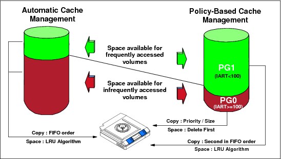
Figure 2-7 TS7740 cache utilization with policy-based cache management
When a preference level has been assigned to a volume, that assignment is persistent until the volume is reused for scratch and a new preference level is assigned. Or, if the policy is changed and a mount/dismount occurs, the new policy also takes effect.
|
Important: As of R2.1, all scratch volumes, independent of their preference group assignment, are favored for migration.
|
Copy files preferred to reside in cache
This function is only available in a multicluster grid. Logical volumes that need to be replicated to one or more peer clusters are retained in disk cache regardless of their preference group assignments. This allows peer clusters to complete the replication process without requiring a recall. After the copy completes, the assigned preference group then takes effect. For example, those assigned as preference group 0 are then immediately migrated.
If replication is not completing and the retention backlog becomes too large, the original preference groups begin to be honored, allowing data not yet replicated to be migrated to tape. These volumes likely need to be recalled into disk cache at a later time in order for replication to complete. The migration of not yet replicated data might be expected when replication is not completing due to an extended outage within the grid.
Recalls preferred for cache removal
Normally, a volume recalled into cache is managed as though it were newly created or modified because it resides in the TVC selected for I/O operations on the volume. A recalled volume displaces other volumes in cache. If the remote cluster of a grid is used for recovery, the recovery time is minimized by having most of the needed volumes in cache.
However, an unlikely situation is that all of the volumes that are used to restore are resident in the cache and that recalls are required. Unless you can explicitly control the sequence of volumes used during restore, recalled volumes likely displace cached volumes that have not yet been restored from, resulting in further recalls at a later time in the recovery process. After a restore process is completed from a recalled volume, that volume is no longer needed. A method is needed with which to remove the recalled volumes from the cache after they have been accessed so that there is minimal displacement of other volumes in the cache.
Based on your current requirements, you can set or modify this control dynamically through the z/OS Host Console Request function on the remote cluster:
•When OFF, which is the default, logical volumes that are recalled into cache are managed by using the actions defined for the Storage Class construct associated with the volume as defined at the TS7700 Virtualization Engine.
•When ON, logical volumes that are recalled into cache are managed as PG0 (preferable to be removed from cache). This control overrides the actions that are defined for the Storage Class associated with the recalled volume.
2.2.15 TVC management processes for TS7740
Two processes manage the TVC of the TS7740 Virtualization Engine in a stand-alone environment:
•Premigration Management (TS7740 only)
This process becomes effective when the amount of TS7740 Virtualization Engine TVC data that is not copied to tape reaches a predefined threshold. It is intended to ensure that the TVC does not become completely full of data that has not been backed up to physical tape.
Be aware that if your TS7740 is already busy, this mechanism might take your Virtualization Engine from peak mode to sustained mode. Threshold values can be tuned to your needs using LIB REQ commands. For details, see 6.5, “TS7700 SETTING function” on page 315.
•Free-space Management (TS7740 only)
This process becomes effective when the amount of unused (free) TVC space reaches another higher predetermined threshold. It is intended to ensure that the TVC does not become completely full of data, copied to physical tape or not. It is the mechanism that keeps the input to the TVC from overrunning the available free space.
If space cannot be freed up quickly enough, that process might lead to host I/O throttling.
2.2.16 TS7720 TVC cache management
In a TS7720 stand-alone cluster, you can only influence the TVC content with the Delete Expired setting. No further cache management is available.
2.2.17 Copy Consistency Point: Copy policy modes in a stand-alone cluster
In a stand-alone cluster, you cannot define any Copy Consistency Point.
2.2.18 TVC selection in a stand-alone cluster
Because there is only one TVC in a stand-alone cluster available, no TVC selection occurs.
2.2.19 TVC encryption
With R3.0, a TVC encryption feature was introduced. This feature allows you to encrypt either a TS7720 or a TS7740 TVC. Because the encryption is done at the disk drive level, encryption is transparent to the TS7700 while still providing great performance.
TVC encryption is turned on for the whole disk cache; you cannot encrypt a disk cache partially. Therefore, all DDMs in all strings must be full disk encryption (FDE)-capable in order to enable the encryption. The disk cache encryption is supported for a TS7720 with 3956-CS9, and for TS7740 with 3956-CC9. Encryption can be enabled in the field at any time.
Starting with R3.0, only local key management is supported. Local key management is completely automated. There are no keys for the user to manage.
2.2.20 Logical and stacked volume pooling
The TS7740 allows you to manage your logical volumes and stacked volumes.
The following concerns are addressed by volume pooling:
•Data from separate customers on the same physical volume can compromise certain outsourcing contracts.
•Customers want to be able to “see, feel, and touch” their data by having only their data on dedicated media.
•Customers need separate pools for different environments (test, User Acceptance Test (UAT), or production).
•Charging for tape is complicated. Traditionally, users are charged by the number of volumes they have in the tape library. With physical volume pooling, users can create and consolidate multiple logical volumes on a smaller number of stacked volumes and therefore reduce their media charges.
•Recall times depend on the media length. Small logical volumes on the tape cartridges (JA, JB, and JC) take a longer time to recall than volumes on the economy cartridge (JJ or JK). Therefore, pooling by media type is also beneficial.
•Some workloads have a high expiration rate, which causes excessive reclamation. These workloads are better suited in their own pool of physical volumes.
•Protecting data through encryption can be set on a per pool basis, which enables you to encrypt all or some of your data when it is written to the back-end tapes.
•Migration from older tape media technology.
•Second dedicated pool for key workloads to be Copy Exported.
There are benefits to using physical volume pooling, so plan for the number of physical pools. See also “Relationship between reclamation and number of physical pools” on page 44.
Physical volume pooling
Volume pooling allows the administrator to define pools of stacked volumes within the TS7740 Virtualization Engine. You can direct virtual volumes to these pools through the use of SMS constructs. There can be up to 32 general-purpose pools (01 - 32) and one common pool (00). A common scratch pool (Pool 00) is a reserved pool that contains only scratch stacked volumes for the other pools.
Each TS7740 Virtualization Engine that is attached to a TS3500 Tape Library has its own set of pools.
Common scratch pool (Pool 00)
The common scratch pool is a pool that only contains scratch stacked volumes and serves as a reserve pool. You can define a primary pool to borrow scratch stacked cartridges from the common scratch pool (Pool 00) if a scratch shortage occurs. This can be done either on a temporary or permanent basis. Each pool can be defined to borrow single media (JA, JB, JC, JJ, or JK), mixed media, or it can have a “first choice” and a “second choice”. The borrowing options can be set at the management interface when defining stacked volume pool properties.
|
Remember: The common scratch pool must have at least three cartridges available.
|
General-purpose pools (Pools 01 - 32)
There are 32 general-purpose pools available for each TS7740 Virtualization Engine cluster. These pools can contain both empty and full/filling stacked volumes. All physical volumes in a TS7740 Virtualization Engine cluster are distributed among available pools according to the physical volume range definitions in place. Those pools can have their properties tailored individually by the administrator for various purposes. When initially creating these pools, it is important to ensure that the correct borrowing properties are defined to each one. For more information, see “Stacked volume pool properties” on page 42.
By default, there is one pool, Pool 01, and the TS7740 Virtualization Engine stores virtual volumes on any stacked volume available to it. This creates an intermix of logical volumes from differing sources, for example, an LPAR and applications on a physical cartridge. The user cannot influence the physical location of the logical volume within a pool. Having all logical volumes in a single group of stacked volumes is not always optimal.
Using this facility, you can also perform the following tasks:
•Separate different clients or LPAR data from each other
•Intermix or segregate media types
•Map separate Storage Groups to the same primary pools
•Set up specific pools for Copy Export
•Set up pool or pools for encryption
•Set a reclamation threshold at the pool level
•Set reclamation parameters for stacked volumes
•Assign or eject stacked volumes from specific pools
Physical pooling of stacked volumes is identified by defining a pool number, as shown in Figure 2-8.

Figure 2-8 TS7740 Logical volume allocation to specific physical volume pool flow
Through the management interface you can add a Storage Group construct, and assign a primary storage pool to it. Stacked volumes are assigned directly to the defined storage pools. The pool assignments are stored in the TS7740 Virtualization Engine database. During a scratch mount, a logical volume is assigned to a selected Storage Group. This Storage Group is connected to a storage pool with assigned physical volumes. When a logical volume is copied to tape, it is written to a stacked volume that belongs to this storage pool.
Physical VOLSER ranges can be defined with a home pool at insert time. Changing the home pool of a range has no effect on existing volumes in the library. When also disabling borrow/return, this provides a method to have a specific range of volumes used exclusively by a specific pool.
|
Tip: Primary Pool 01 is the default private pool for TS7740 Virtualization Engine stacked volumes.
|
Borrowing and returning
Using the concept of borrowing and returning, out of scratch scenarios can be automatically addressed. Ensure that non-borrowing active pools have at least two scratch volumes.
With borrowing, stacked volumes can move from pool to pool and back again to the original pool. In this way, the TS7740 Virtualization Engine can manage out of scratch and low scratch scenarios, which can occur within any TS7740 Virtualization Engine from time to time.
|
Remember: Pools that have borrow/return enabled that contain no active data will eventually return all scratch volumes to the common scratch pool after 48 - 72 hours of inactivity.
|
Stacked volume pool properties
Logical volume pooling supports cartridge type selection. This can be used to create separate pools of 3592 tape cartridges with a variety of capacities from 128 GB up to 4 TB, depending upon the type of media and tape drive technology used.
Lower capacity JJ or JK cartridges can be designated to a pool to provide fast access to applications, such as hierarchical storage management (HSM) or Content Manager. Higher capacity JA, JB, or JC cartridges assigned to a pool can address archival requirements, such as full volume dumps.
2.2.21 Logical and stacked volume management
Every time that a logical volume is modified (either by modification or by reuse of a scratch volume), the data from the previous use of this logical volume, which is on a stacked volume, becomes obsolete. The new virtual volume is placed in the cache and written to a stacked volume afterward (TS7740 only).The copy on the stacked volume is invalidated, but it still exists in its current state on the physical volume.
Virtual volume reconciliation
The reconciliation process checks for invalidated volumes. A reconciliation is that period of activity by the TS7740 Virtualization Engine when the most recent instance of a logical volume is determined as the active one, and all other instances of that volume are deleted from the active volume list. This process automatically adjusts the active data amount for any stacked volumes that hold invalidated logical volumes.
The data that is associated with a logical volume is considered invalidated if any of the following statements are true:
•A host has assigned the logical volume to a scratch category. The volume is subsequently selected for a scratch mount and data is written to the volume. The older version of the volume is now invalid.
•A host has assigned the logical volume to a scratch category. The category has a non-zero delete-expired data parameter value. The parameter value has been exceeded, and the TS7740 Virtualization Engine has deleted the logical volume.
•A host has modified the contents of the volume. This can be a complete rewrite of the volume or an append to it. The new version of the logical volume is pre-migrated to a separate physical location and the older version is invalidated.
The TS7740 Virtualization Engine keeps track of the amount of active data on a physical volume. It starts at 100% when a volume becomes full. Although the granularity of the percentage of full TS7740 Virtualization Engine tracks is one tenth of 100%, it rounds down, so even one byte of inactive data drops the percentage to 99.9%. TS7740 Virtualization Engine keeps track of the time that the physical volume went from 100% full to less than 100% full by performing the following tasks:
•Checking on an hourly basis for volumes in a pool with a non-zero setting
•Comparing this time against the current time to determine whether the volume is eligible for reclamation
Physical volume reclamation
Physical volume reclamation consolidates active data and frees stacked volumes for return-to-scratch use. Reclamation is part of the internal management functions of a TS7740 Virtualization Engine.
The reclamation process is basically a tape-to-tape copy. The physical volume to be reclaimed is mounted to a physical drive, and the active logical volumes that reside there are copied to another filling cartridge under control of the TS7740 Virtualization Engine. One reclamation task needs two physical tape drives to run. At the end of the reclaim, the source volume is empty and it is returned to the specified reclamation pool as an empty (scratch) volume. The data being copied from the reclaimed physical volume does not go to the TVC, instead it is transferred directly from the source to the target tape cartridge.
Physical tape volumes become eligible for space reclamation when they cross the occupancy threshold level specified by the administrator in the home pool definitions where those tape volumes belong. This reclaim threshold is set for each pool individually according to the specific needs for that client and is expressed in a percentage (%) of tape utilization.
Volume reclamation can be concatenated with a Secure Data Erase for that volume, if required. This causes the volume to be erased after that reclamation finishes. For more details, see 2.2.22, “Secure Data Erase function” on page 44. Do not run reclamation during peak workload hours of the TS7740. This is necessary to ensure that recalls and migrations are not delayed due to physical drive shortages. You must choose the best period for reclamation by considering the workload profile for that TS7740 cluster and inhibit reclamation during the busiest period for the machine.
A physical volume that is being ejected from the library is also reclaimed in a similar way before being allowed to be ejected. The active logical volumes contained in the cartridge are moved to another physical volume, according to the policies defined in the volume’s home pool, before the physical volume is ejected from the library.
Reclamation also can be used to migrate older data from a pool to another while it is being reclaimed, but only by targeting a separate specific pool for reclamation.
Relationship between reclamation and number of physical pools
The reclaim process is done on a pool basis and each reclamation process needs two drives. If you define too many pools, it can lead to a situation where the TS7740 is incapable of processing the reclamation for all pools in an appropriate manner. Eventually, pools can run out of space (depending on the “borrow: definitions), or you need more stacked volumes than planned.
The number of physical pools, physical drives, stacked volumes in the pools, and the available time tables for reclaim schedules must be considered and balanced.
2.2.22 Secure Data Erase function
Another concern is the security of old data. The TS7740 Virtualization Engine provides physical volume erasure on a physical volume pool basis that is controlled by an additional reclamation policy. When Secure Data Erase is enabled, a physical cartridge is not available as a scratch cartridge as long as its data is not erased.
The Secure Data Erase function supports the erasure of a physical volume as part of the reclamation process. The erasure is performed by running a long erase procedure against the media.
A Long Erase operation on a TS11xx drive is completed by writing a repeating pattern from the beginning to the end of the physical tape, making all data previously present inaccessible through traditional read operations.
The key here is that it is not a fully random from beginning to end pattern and it only has one pass. That is why it is not officially a Secure Data Erase as described in the DOD or Department of Defense documentation.
Therefore, the logical volumes written on this stacked volume are no longer readable. As part of this data erase function, an additional reclaim policy is added. The policy specifies the number of days that a physical volume can contain invalid logical volume data before the physical volume becomes eligible to be reclaimed.
When a physical volume contains only encrypted data, the TS7740 Virtualization Engine is able to perform a fast erase of the data by erasing the encryption keys on the cartridge. Basically, it erases only the portion of the tape where the key information is stored. This form of erasure is referred to as a cryptographic erase. Without the key information, the rest of the tape cannot be read. This method significantly reduces the erasure time. Any physical volume that has a status of read-only is not subject to this function and is not designated for erasure as part of a read-only recovery.
If you use the eject stacked volume function, the data on the volume is not erased before ejecting. The control of expired data on an ejected volume is your responsibility.
Volumes tagged for erasure cannot be moved to another pool until erased, but they can be ejected from the library because such a volume is usually removed for recovery actions.
Using the Move function also causes a physical volume to be erased, even though the number of days specified has not yet elapsed. This includes returning borrowed volumes.
2.2.23 Copy Export function
One of the key reasons to use tape is for recovery of critical operations in a disaster. If you are using a grid configuration designed for DR purposes, the recovery time objectives and recovery point objectives (RPO) can be measured in seconds. In case you do not require such low recovery times for all or a mixture of your workload, there is a function called Copy Export for the TS7740 Virtualization Engine.
The Copy Export function allows a copy of selected logical volumes written to secondary pools within the TS7740 Virtualization Engine to be removed and taken offsite for DR purposes. The benefits of volume stacking, which places many logical volumes on a physical volume, are retained with this function. Because the physical volumes being exported are from a secondary physical pool, the primary logical volume remains accessible to the production host systems.
The following logical volumes are excluded from the export:
•Mounted volumes
•Volumes without an invalid copy in the primary pool
•Volumes not yet replicated from other clusters
The Copy Export sets can be used to restore data at a location that has equal or newer tape technology and equal or newer TS7700 microcode.
There is an offsite reclamation process against copy-exported stacked volumes. For more information, see 11.5.3, “Reclaim process for Copy Export physical volumes” on page 795.
2.2.24 Encryption of physical tapes
The importance of data protection has become increasingly apparent with news reports of security breaches, loss and theft of personal and financial information, and government regulation. Encrypting the stacked cartridges minimizes the risk of unauthorized data access without excessive security management burdens or subsystem performance issues.
The encryption solution for tape virtualization consists of several components:
•The encryption key manager
•The TS1120, TS1130, and TS1140 encryption-enabled tape drives
•The TS7740 Virtualization Engine
Encryption key manager
TS7700 Virtualization Engine can use one of the following encryption key managers:
•Encryption Key Manager (EKM)
•IBM Tivoli Key Lifecycle Manager
•IBM Security Key Lifecycle Manager
We use the general term key manager for all three encryption key managers.
|
Important: The EKM is no longer available and does not support the TS1140. If you need encryption support for the TS1140, you need to install either IBM Tivoli Key Lifecycle Manager or IBM Security Key Lifecycle Manager.
|
The key manager is the central point from which all encryption key information is managed and served to the various subsystems. The key manager server communicates with the TS7740 Virtualization Engine and tape libraries, control units, and Open Systems device drivers.
For more information, see 4.6.8, “Planning for tape encryption in the TS7740 Virtualization Engine” on page 171.
The TS1120, TS1130, and TS1140 encryption-enabled tape drives
The IBM TS1120, TS1130, and TS1140 tape drives provide hardware that performs the encryption without reducing the data transfer rate.
The TS7740 Virtualization Engine
The TS7740 provides the means to manage the use of encryption and the keys that are used on a storage pool basis. It also acts as a proxy between the tape drives and the key manager servers, using redundant Ethernet to communicate with the key manager servers and Fibre Channel connections to communicate with the drives. Encryption must be enabled in each of the tape drives.
Encryption on the TS7740 Virtualization Engine is controlled on a storage pool basis. The Storage Group DFSMS construct that is specified for a logical tape volume determines which storage pool is used for the primary and optional secondary copies in the TS7740 Virtualization Engine. The storage pools were originally created for management of physical media, and they have been enhanced to include encryption characteristics. Storage pool encryption parameters are configured through the TS7740 Virtualization Engine management interface under “Physical Volume Pools”.
For encryption support, all drives that are attached to the TS7740 Virtualization Engine must be encryption-capable and encryption must be enabled. If TS7740 Virtualization Engine uses TS1120 Tape Drives, they must also be enabled to run in their native E05 format. The management of encryption is performed on a physical volume pool basis. Through the management interface, one or more of the 32 pools can be enabled for encryption.
Each pool can be defined to use specific encryption keys or the default encryption keys defined at the key manager server:
•Specific encryption keys
Each pool that is defined in the TS7740 Virtualization Engine can have its own unique encryption key. As part of enabling a pool for encryption, enter two key labels for the pool and an associated key mode. The two keys might or might not be the same. Two keys are required by the key manager servers during a key exchange with the drive. A key label can be up to 64 characters. Key labels do not have to be unique per pool. The management interface provides the capability to assign the same key label to multiple pools. For each key, a key mode can be specified. The supported key modes are Label and Hash. As part of the encryption configuration through the management interface, you provide IP addresses for a primary and an optional secondary key manager.
•Default encryption keys
The TS7740 Virtualization Engine encryption supports the use of a default key. This support simplifies the management of the encryption infrastructure because no future changes are required at the TS7740 Virtualization Engine. After a pool is defined to use the default key, the management of encryption parameters is performed at the key manager:
– Creation and management of encryption certificates
– Device authorization for key manager services
– Global default key definitions
– Drive-level default key definitions
– Default key changes as required by security policies
For logical volumes that contain data that is to be encrypted, host applications direct them to a specific pool that has been enabled for encryption using the Storage Group construct name. All data directed to a pool enabled for encryption is encrypted when it is pre-migrated to the physical stacked volumes or reclaimed to the stacked volume during the reclamation process. The Storage Group construct name is bound to a logical volume when it is mounted as a scratch volume.
Through the management interface, the Storage Group name is associated with a specific pool number. When the data for a logical volume is copied from the TVC to a physical volume in an encryption-enabled pool, the TS7740 Virtualization Engine determines whether a new physical volume needs to be mounted. If a new cartridge is required, the TS7740 Virtualization Engine directs the drive to use encryption during the mount process.
The TS7740 Virtualization Engine also provides the drive with the key labels specified for that pool. When the first write data is received by the drive, a connection is made to a key manager and the key that is needed to perform the encryption is obtained. Physical scratch volumes are encrypted with the keys in effect at the time of first write to BOT. Any partially filled physical volumes continue to use the encryption settings in effect at the time that the tape was initially written from BOT. The encryption settings are static until the volumes are reclaimed and rewritten again from BOT.
Figure 2-9 on page 48 illustrates that the method for communicating with a key manager is through the same Ethernet interface that is used to connect the TS7740 Virtualization Engine to your network for access to the management interface. The request for an encryption key is directed to the IP address of the primary key manager. Responses are passed through the TS7740 Virtualization Engine to the drive. If the primary key manager did not respond to the key management request, the optional secondary key manager IP address is used. After the TS1120 or TS1130 drive has completed the key management communication with the key manager, it accepts data from the TVC.
When a logical volume needs to be read from a physical volume in a pool enabled for encryption, either as part of a recall or reclamation operation, the TS7740 Virtualization Engine uses the key manager to obtain the necessary information to decrypt the data.
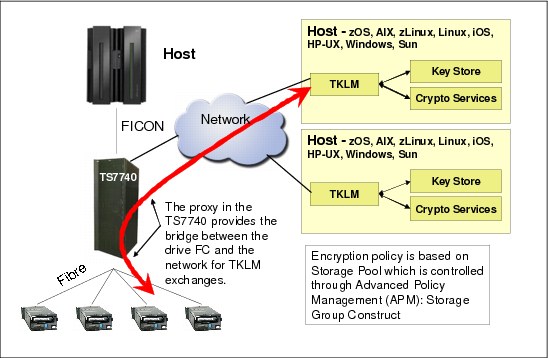
Figure 2-9 TS7740 Virtualization Engine encryption
The affinity of the logical volume to a specific encryption key or the default key can also be used as part of the search criteria through the TS7700 Virtualization Engine management interface.
2.2.25 Security identification via Lightweight Directory Access Protocol
Previous implementations are based on Tivoli System Storage Productivity Center to authenticate users to a client’s Lightweight Directory Access Protocol (LDAP) server. Beginning with Release 3.0 of Licensed Internal Code, both the TS7700 clusters and TS3000 System Console have native support for an LDAP server (at this time, only Microsoft Active Directory is supported).
Starting with R3.0, when LDAP is enabled, the TS7700 Management Interface is controlled by the LDAP server. Also, the local actions executed by the IBM SSR are controlled by the LDAP server. All IBM standard users cannot access the system anymore. You must have a valid account in the LDAP server, along with the roles assigned to your user, to be able to communicate with the TS7700 Virtualization Engine.
If your LDAP server is not available, you are not able to interact with TS7700 Virtualization Engine (neither IBM SSR or operator).
|
Important: Create at least one external authentication policy for IBM SSRs before a service event.
|
2.2.26 Service preparation mode
This function is only available in a multicluster grid.
2.2.27 Service mode
This function is only available in a multicluster grid.
2.3 Multicluster grid configurations: Components, functionality, and features
Multicluster grids are combinations of two clusters, three clusters, four clusters, five clusters, or six clusters working together as one logical entity. TS7720 and TS7740 can be combined together as a hybrid grid, but you can also form a grid just from TS7720 or TS7740 clusters. The configuration that is suitable for you depends on your requirements.
To allow multiple clusters to work together as a multicluster grid, some hardware configurations must be provided. Also, logical considerations need to be planned and implemented. The following topics are described:
•The base rules that apply in a multicluster grid
•Required grid hardware
•Implementation concepts for the grid
•Components and features used in a grid
Figure 2-10 shows a four-cluster hybrid grid. The configuration consists of two TS7720 Virtualization Engines and two TS7740 Virtualization Engines. More examples are available in 2.4, “Grid configuration examples” on page 79.

Figure 2-10 TS7720 Virtualization Engine four-cluster grid
2.3.1 Rules in multicluster grid
In a multicluster grid, some general rules apply:
•A grid configuration looks like a single tape library and tape drives to the hosts.
•It is a composite library with underlying distributed libraries.
•Up to six clusters can form a grid.
•Data integrity is accomplished by the concept of volume ownership.
•The TS7720 and TS7740 can coexist in a grid (hybrid grid).
•If one cluster is not available, the grid still continues to work.
•Mounts (scratch (Fast Ready) and private (non-Fast Ready) can be satisfied from any cluster in the grid, controlled by your implementation.
•Clusters can be grouped into cluster families.
|
Remember: Five-cluster grid and six-cluster grid configurations are available with an RPQ.
|
In a multicluster grid, some rules for virtual/logical volumes apply:
•You can store a logical volume/virtual volume in the following ways:
– Single instance in only one cluster in a grid.
– Multiple instances (two, three, four, five, or six) in different clusters in the grid up to the number of clusters in the grid.
– Each TS7740 cluster in the grid can store dual copies on physical tape. Each copy is a valid source for the virtual/logical volume.
– Selective dual copy is still a valid option in a TS7740. (In an extreme case, you can end up with 12 instances of the same data.)
•You control the number of instances and the method of how the instances are generated through different copy policies.
In a multicluster grid, the following rules for access to the virtual/logical volumes apply:
•A logical volume can be accessed from any virtual device in the system.
•Any logical volume (replicated or not) is accessible from any other cluster in the grid.
•Each distributed library has access to any logical volumes within the entire composite library.
|
Note: You can still restrict access to clusters via host techniques (HCD).
|
With this flexibility, the TS7700 grid provides many options for business continuance and data integrity, meeting requirements for a minimal configuration up to the most demanding advanced configurations.
2.3.2 Required grid hardware
To allow you to combine single clusters into a grid, several requirements must be met:
•Each of the TS7700 Virtualization Engines must have the Grid Enablement feature installed.
•Each of the TS7700 engines must be connected to all other clusters in the grid through the grid network. Each cluster can have two or four links to the grid network.
Grid enablement
FC4015 must be installed on all clusters in the grid.
Grid network
A grid network is the client-supplied TCP/IP infrastructure that interconnects the TS7700 grid. Each cluster has two Ethernet adapters that are connected to the TCP/IP infrastructure. Adapters can be a dual-ported copper 1 GBps adapter, dual-ported 1 Gbps shortwave optical fiber adapters, or a (single-port or dual-port) 10 Gbps long-wave optical fiber adapter. This accounts for two or four grid links, depending on the cluster configuration. See 2.5.1, “Common components for the TS7720 Virtualization Engine and TS7740 Virtualization Engine models” on page 86.
Earlier TS7740 Virtualization Engines might still have the single-port adapters for the copper connections and shortwave 1 Gbps connections. A miscellaneous equipment specification (MES) is available to upgrade the single port to dual-port adapters.
Dynamic Grid Load Balancing
Dynamic Grid Load Balancing is an algorithm that is used within the TS7700 Virtualization Engine. It continually monitors and records the rate at which data is processed by each network link. Whenever a new task starts, the algorithm uses the stored information to identify the link that will most quickly complete the data transfer. The algorithm also identifies degraded link performance and sends a warning message to the host.
Remote mount automatic IP failover
If a grid link fails during a remote mount, the Remote Mount IP Link Failover function attempts to reestablish the connection through an alternate link. During a failover, up to three additional links are attempted. If all configured link connections fail, the remote mount fails, resulting in a host job failure or a Synchronous mode copy break. When a remote mount or a Synchronous copy is in use and a TCP/IP link failure occur, this intelligent failover function recovers by using an alternate link. The following restrictions apply:
•Each cluster in the grid must operate using a microcode level of 8.21.0.xx or higher.
•At least two grid connections must exist between clusters in the grid (either two or four
1 Gbps grid links or two 10 Gbps grid links).
1 Gbps grid links or two 10 Gbps grid links).
Internet Protocol Security for grid links
When running the TS7700 R3.0 level of Licensed Internal Code, the 3957-V07 and 3957-VEB models support Internet Protocol Security (IPSec) on the grid links. Only use IPSec capabilities if absolutely required by the nature of your business.
|
Note: Enabling grid encryption significantly affects the overall performance of the TS7700 Virtualization Engine grid.
|
Data and Time coordination
All nodes in the grid subsystem coordinate their time with one another. All nodes in the system keep track of time in relation to Coordinated Universal Time (UTC). Statistics are also reported in relation to UTC.
The preferred method to keep nodes synchronized is by using a Network Time Protocol (NTP) server. The NTP server can be a part of the grid WAN infrastructure, your intranet, or a public server on the Internet (Figure 2-11).

Figure 2-11 Time coordination with NTP servers
The NTP server address is configured into the system vital product data (VPD) on a system-wide scope. Therefore, all nodes access the same NTP server. All clusters in a grid need to be able to communicate with the same NTP server defined in VPD. In the absence of an NTP server, all nodes coordinate time with Node 0 or the lowest cluster index designation. The lowest index designation is Cluster 0, if Cluster 0 is available. If not, it uses the next available cluster.
2.3.3 Data integrity by volume ownership
In a multicluster grid, ensure that only one cluster at a time modifies the data of a logical volume. Therefore, the concept of ownership was introduced.
Ownership
Any logical volume, or any copies of it, can be accessed by a host from any virtual device participating in a common grid, even if the cluster associated with the virtual device does not have a local copy. The access is subject to volume ownership rules. At any point in time, a logical volume is “owned” by only one cluster. The owning cluster controls access to the data and the attributes of the volume.
|
Note: The volume ownership protects the volume from being accessed or modified by multiple clusters simultaneously.
|
Ownership can change dynamically. If a cluster needs to mount a logical volume on one of its virtual devices and it is not the owner of that volume, it must obtain ownership first. When required, the TS7700 Virtualization Engine node transfers the ownership of the logical volume as part of mount processing. This action ensures that the cluster with the virtual device associated with the mount has ownership.
If the TS7700 Virtualization Engine clusters in a grid and the communication paths between them are operational, the change of ownership and the processing of logical volume-related commands are transparent to the host. If a TS7700 Virtualization Engine Cluster has a host request for a logical volume that it does not own and it cannot communicate with the owning cluster, the operation against that volume fails unless additional direction is given. Clusters do not automatically assume or take ownership of a logical volume without being directed. This can either be done manually, or can be automated with the Autonomic Ownership Takeover Manager (AOTM).
To support the concept of ownership, it was necessary to introduce tokens.
Tokens
Tokens are used to track changes to the ownership, data, or properties of a logical volume. The tokens are mirrored at each cluster that participates in a grid and represent the current state and attributes of the logical volume. Tokens have the following characteristics:
•Every logical volume has a corresponding token.
•The grid component manages updates to the tokens.
•Tokens are maintained in an IBM DB2® database coordinated by the local hNodes.
•Each cluster’s DB2 database has a token for every logical volume in the grid.
Tokens are internal data structures that are not directly visible to you. However, they can be retrieved through reports generated with the Bulk Volume Information Retrieval (BVIR) facility.
Tokens are part of the architecture of the TS7700. Even in a stand-alone cluster, they exist and are used in the same way as they are used in the grid configuration - with only one cluster doing the updates and keeping the database. In a grid configuration, all members in grid have the information for all tokens (also known as logical volumes) within the composite library mirrored in each cluster. Token information is updated real time at all clusters in a grid.
Ownership takeovers
In some situations, the ownership of the volumes might not be transferable, for example, if a TS7700 Virtualization Engine Cluster has failed if the grid links are not available.
Without the Autonomic Ownership Takeover Manager, you need to take over manually. The following options are available:
•Read-only Ownership Takeover
When Read-only Ownership Takeover is enabled for a failed cluster, ownership of a volume is taken from the failed TS7700 Virtualization Engine Cluster. Only read access to the volume is allowed through the other TS7700 Virtualization Engine clusters in the grid. After ownership for a volume has been taken in this mode, any operation attempting to modify data on that volume or change its attributes fails. The mode for the failed cluster remains in place until another mode is selected or the failed cluster has been restored.
•Write Ownership Takeover
When Write Ownership Takeover is enabled for a failed cluster, ownership of a volume is taken from the failed TS7700 Virtualization Engine Cluster. Full access is allowed through the requesting TS7700 Virtualization Engine Cluster in the grid, and all other available TS7700 Virtualization Engine clusters in the grid. The automatic ownership takeover method used during a service outage is essentially identical to Write Ownership Takeover, but without the need for a person or AOTM to initiate it. The mode for the failed cluster remains in place until another mode is selected or the failed cluster has been restored.
Scratch mounts continue to prefer volumes owned by the available clusters. Only after all available candidates have been exhausted does it begin to take over a scratch volume from the unavailable cluster.
You can set the level of ownership takeover, Read-only or Write, through the TS7700 Virtualization Engine management interface.
In the service preparation mode of a TS7700 cluster, ownership takeover is automatically enabled allowing remaining clusters to gracefully take over volumes with full read and write access. The mode for the cluster in service remains in place until it is taken out of service mode.
|
Note: You cannot set a cluster in service preparation after it has already failed.
|
For more information about an automatic takeover, see 2.3.33, “Autonomic Ownership Takeover Manager” on page 77.
2.3.4 I/O TVC selection
All vNodes in a grid have direct access to all logical volumes in the grid. The cluster selected for the mount is not necessarily the cluster that is chosen for I/O TVC selection. All I/O operations associated with the virtual tape drive are routed to and from its vNode to the I/O TVC.
When a TVC, which is different from the local TVC at the actual mount point, is chosen, this is called a remote mount. The TVC is then accessed by the grid network.
You have several ways to influence the TVC selection. During the logical volume mount process, the best TVC for your requirements is selected:
•Availability of the cluster
•Copy Consistency Policies and settings
•Scratch allocation assistance (SAA) for scratch mount processing
•DAA for specific mounts
•Override settings
•Cluster family definitions
2.3.5 Copy Consistency Points
In a multicluster grid configuration, there are several policies and settings that can be used to influence the location of data copies and when the copies are executed.
Consistency point management is controlled through the Management Class storage construct. Using the management interface, you can create Management Classes and define where copies reside and when they will be synchronized relative to the host job that created them.
Depending on your business needs for more than one copy of a logical volume, multiple Management Classes, each with a separate set of definitions, can be created.
The following key questions help to determine copy management in the TS7700 Virtualization Engine:
•Where do I want my copies to reside?
•When do I want my copies to become consistent with the originating data?
•Do I want logical volume copy mode retained across all grid mount points?
For different business reasons, data can be synchronously created in two places, copied immediately, or copied asynchronously.
Copies are pulled and not pushed within a grid configuration. The cluster acting as the mount cluster informs the appropriate clusters that copies are required and the method they need to use. It is then the responsibility of the target clusters to choose an optimum source and pull the data into its disk cache.
There are currently four available consistency point settings:
Sync As data is written to the volume, it is compressed and then simultaneously written or duplexed to two TS7700 locations. The mount point cluster is not required to be one of the two locations. Memory buffering is utilized to improve the performance of writing to two locations. Any pending data buffered in memory will be hardened to persistent storage at both locations only when an implicit or explicit sync operation occurs. This provides a zero RPO at tape sync point granularity. Tape workloads in System z already assume sync point hardening through explicit sync requests or during close processing, allowing this mode of replication to be performance friendly in a tape workload environment. When Sync is used, two clusters must be defined as sync points. All other clusters can be any of the remaining consistency point options, allowing additional copies to be made.
RUN The copy occurs as part of the Rewind Unload (RUN) operation and completes before the Rewind Unload operation at the host finishes. This mode is comparable to the immediate copy mode of the Peer-to-Peer (PtP) VTS.
Deferred The copy occurs after the Rewind Unload operation at the host. This mode is comparable to the Deferred copy mode of the PtP VTS. This is also referred to as Asynchronous replication.
No Copy No copy is made.
On each cluster in a multicluster grid, a Copy Consistency Point setting is specified for the local cluster and one for each of the other clusters. The settings can be different on each cluster in the grid. When a volume is mounted on a virtual tape device, the Copy Consistency Point policy of the cluster to which the virtual device belongs is honored, unless Retain Copy mode has been turned on at the Management Class.
For more information, see 2.3.25, “Copy Consistency Point: Copy policy modes in a multicluster grid” on page 70.
|
Remember: The mount point (allocated virtual device) and the actual TVC used might be in different clusters. The Copy Consistency Policy is one of the major parameters used to control the TVC.
|
2.3.6 Cluster family concept
In the early releases, you were only able to use the Copy Consistency Points to direct who gets a copy of data and when they get the copy. Decisions about from where to source a volume were left to each cluster in the grid. Two copies of the same data can be transmitted across the grid links for two distant clusters. You can make the copying of data to other clusters more efficient by influencing where a copy of data is sourced. This becomes important with three to six cluster grids where the clusters can be geographically separated.
For example, two clusters are at one site and the other two are at a remote site. When the two remote clusters need a copy of the data, cluster families enforce that only one copy of the data is sent across the long grid link. Also, when deciding where to source a volume, a cluster gives higher priority to a cluster in its family over another family. A cluster family establishes a special relationship between clusters. Typically, families are grouped by geographical proximity to optimize the use of grid bandwidth. Family members are given higher weight when deciding which cluster to prefer for TVC selection.
Figure 2-12 illustrates how cooperative replication occurs with cluster families. Cooperative replication is used for Deferred copies only. When a cluster needs to pull a copy of a volume, it prefers a cluster within its family. The example uses Copy Consistency Points of Run, Run, Deferred, Deferred [R,R,D,D]. With cooperative replication, one of the family B clusters at the DR site pulls a copy from one of the clusters in production family A. The second cluster in family B waits for the other cluster in family B to finish getting its copy, then pulls it from its family member. This way the volume travels only once across the long grid distance.

Figure 2-12 Cluster families
Cooperative replication includes another layer of consistency. A family is considered consistent when only one member of the family has a copy of a volume. Because only one copy is required to be transferred to a family, the family is consistent after the one copy is complete. Because a family member prefers to get its copy from another family member instead of getting the volume across the long grid link, the copy time is much shorter for the family member. Because each family member is pulling a copy of a separate volume, this will make a consistent copy of all volumes to the family quicker. With cooperative replication, a family prefers retrieving a new volume that the family does not have a copy of yet, over copying a volume within a family. When fewer than 20, or the number of configured replication tasks, new copies are made from other families, the family clusters copy among themselves.
Second copies of volumes within a family are deferred in preference to new volume copies into the family. Without families, a source cluster attempts to keep the volume in its cache until all clusters needing a copy have gotten their copy. With families, a cluster’s responsibility to keep the volume in cache is released after all families needing a copy have it. This way allows PG0 volumes in the source cluster to be removed from cache sooner.
Another benefit is the improved TVC selection in cluster families. For cluster families already using cooperative replication, the TVC algorithm favors using a family member as a copy source. Clusters within the same family are favored by the TVC algorithm for remote (cross) mounts. This favoritism assumes all other conditions are equal for all the grid members.
See the following resources for details about cluster families:
•IBM Virtualization Engine TS7700 Series Best Practices -TS7700 Hybrid Grid Usage:
•TS7700 Technical Update (R1.7) and Hybrid Grid Best Practices:
2.3.7 Override settings concept
With the prior generation of PtP VTS, there were several optional override settings that influenced how an individual VTC selected a VTS to perform the I/O operations for a mounted tape volume. In the existing VTS, the override settings were only available to an IBM SSR. With the TS7700 Virtualization Engine, you define and set the optional override settings that influence the selection of the I/O TVC and replication responses through the management interface.
TS7700 Virtualization Engine overrides I/O TVC selection and replication response
The settings are specific to a cluster, which means that each cluster can have separate settings, if desired. The settings take effect for any mount requests received after the settings were saved. All mounts, independent of which Management Class is used, will use the same override settings. Mounts already in progress are not affected by a change in the settings. The following override settings are supported:
•Prefer Local Cache for Fast Ready Mount Requests
This override prefers the mount point cluster as the I/O TVC for scratch mounts if it is available and contains a valid copy consistency definition other than No Copy.
•Prefer Local Cache for non-Fast Ready Mount Requests
This override prefers the mount point cluster as the I/O TVC for private mounts if it is available, contains a valid copy consistency definition other than No Copy, and contains a valid copy of the volume. If the local valid copy only resides on back-end physical tape, a recall occurs versus using a remote cache resident copy.
•Force Local TVC to have a copy of the data
The default behavior of the TS7700 Virtualization Engine is to only make a copy of the data based on the definitions of the Management Class associated with the volume mounted and to select an I/O TVC that was defined to have a copy and a valid Copy Consistency Point defined. If the mount vNode is associated with a cluster for which the specified Management Class defined a Copy Consistency Point of No Copy, a copy is not made locally and all data access is to a remote TVC.
In addition, if the mount vNode has a specified defined Copy Consistency Point of Deferred, remote Rewind Unload clusters are preferred. This override has the effect of overriding the specified Management Class with a Copy Consistency Point of Rewind Unload for the local cluster independent of its currently configured Copy Consistency Point. In addition, it requires that the local cluster always be chosen as the I/O TVC. If the mount type is private (non-Fast Ready) and a consistent copy is unavailable in the local TVC, a copy is performed to the local TVC before mount completion. The copy source can be any participating TS7700 Virtualization Engine in the grid. In a TS7740 Virtualization Engine, the logical volume might have to be recalled from a stacked cartridge. If, for any reason, the vNode cluster is not able to act as the I/O TVC, a mount operation fails even if remote TVC choices are still available when this override is enabled.
The override does not change the definition of the Management Class. It serves only to influence the selection of the I/O TVC or force a local copy.
•Copy Count Override
This override limits the number of RUN consistency points in a multicluster grid that must be consistent before the surfacing device end to a Rewind Unload command. Only Copy Consistency Points of RUN are counted. For example, in a three-cluster grid, if the Management Class specifies Copy Consistency Points of RUN, RUN, RUN, and the override is set to two, initial status or device end is presented after at least two clusters configured with a RUN consistency point are consistent. This includes the original I/O TVC if that site is also configured with a Rewind Unload consistency point. The third RUN consistency point is downgraded to a Deferred copy after at least two of the three RUN consistency points are proven to be consistent. The third site that has its Copy Consistency Point downgraded to Deferred is called the floating deferred site. A floating deferred site has not completed its copy when the Copy Count value has been reached.
•Ignore cache preference groups for copy priority
If this option is selected, copy operations ignore the cache preference group when determining the priority of volumes copied to other clusters. When not set, preference group 0 volumes are preferred in order to allow the source cluster, which retains the volume in cache for replication purposes, to migrate the volume as quickly as possible. When set, the priority is in first-in first-out (FIFO) order.
Overrides for Geographically Dispersed Parallel Sysplex (GDPS)
The default behavior of the TS7700 Virtualization Engine is to follow the Management Class definitions and configuration characteristics to provide the best overall job performance. In certain IBM Geographically Dispersed Parallel Sysplex™ (IBM GDPS®) use cases, all I/O must be local to the mount vNode. There can be other requirements, such as DR testing, where all I/O must only go to the local TVC to ensure that the correct copy policies have been implemented and that data is available where required.
In these GDPS use cases, you must set the Force Local TVC override to ensure that the local TVC is selected for all I/O. This setting includes the following options:
•Prefer Local for Fast Ready Mounts
•Prefer Local for non-Fast Ready Mounts
•Force Local TVC to have a copy of the data
Do not use the Copy Count Override in a GDPS environment.
2.3.8 Host view of a multicluster grid and Library IDs
As well as the stand-alone cluster, the grid is represented by only one composite library to the host. But each of the multiple TS7700 Virtualization Engines must have a unique distributed library defined. It is necessary in order to allow the host to differentiate between the entire grid versus each cluster within the grid. This differentiation is required for messages and certain commands that target the grid or clusters within the grid.
Composite library
The composite library is the logical image of all clusters in a multicluster grid and is presented to the host as a single library. The host sees a logical tape library with up to 96 control units.
The virtual tape devices are defined for the composite library only.
Figure 2-13 illustrates the host view of a three-cluster grid configuration.

Figure 2-13 TS7700 Virtualization Engine three-cluster grid configuration
Distributed library
Each cluster in a grid is a distributed library, which consists of a TS7700 Virtualization Engine. In a TS7740 Virtualization Engine, it is also attached to a physical TS3500 tape library. Each distributed library can have up to sixteen 3490E tape controllers per cluster. Each controller has sixteen IBM 3490E tape drives, and is attached through up to four FICON channel attachments per cluster. However, the virtual drives and the virtual volumes are associated with the composite library.
There is no difference to a stand-alone definition.
2.3.9 Tape Volume Cache
In general, the same rules apply as for stand-alone clusters.
However, in a multicluster grid, the different TVCs from all clusters are potential candidates for containing logical volumes. The group of TVCs can act as one composite TVC our storage cloud, which has the ability to influence:
•TVC management
•“Out of cache resources” conditions
•Selection of I/O cache
For more information, see 2.3.20, “General TVC management in multicluster grids” on page 64 and 2.3.25, “Copy Consistency Point: Copy policy modes in a multicluster grid” on page 70.
2.3.10 Virtual volumes and logical volumes
There is no difference between multicluster grids and stand-alone cluster.
|
Remember: With V07/VEB servers and R3.0, the number of supported virtual volumes is 4,000,000 virtual volumes per stand-alone cluster or multicluster grid. The default maximum number of supported logical volumes is still 1,000,000 per grid. Support for additional logical volumes can be added in increments of 200,000 volumes using FC5270.
Important: All clusters in a grid must have the same quantity of installed instances of FC5270 configured. If you have configured different FC5270s in clusters combined to a grid, the cluster with the lowest number of virtual volumes constrains all other clusters. Only this number of virtual volumes is then available in the grid.
|
2.3.11 Mounting a scratch virtual volume
In addition to the stand-alone capabilities, you can use scratch allocation assistance (SAA). This function widens the standard DAA support (for specific allocations) to scratch allocations and allows you to direct a scratch mount to a set of specific “candidate” clusters. For more information, see “Scratch allocation assistance” on page 63.
2.3.12 Mounting a specific virtual volume
A mount for a specific volume can be issued to any device within any cluster in a grid configuration. With no additional assistance, the mount uses the TVC I/O selection process to locate a valid version of the volume.The following scenarios are possible:
1. There is a valid copy in the TVC of the cluster where the mount is placed. In this case, the mount is signaled as complete and the host can access the data immediately.
2. There is no valid copy in the TVC of the cluster where the mount is placed. In this case, there are further options:
a. Another cluster has a valid copy already in cache. The virtual volume is read over the grid link from the “remote cluster”, which is called a remote mount. No physical mount occurs. In this case, the mount is signaled as complete and the host can access the data immediately. However, the data is accessed through the grid network from a different cluster.
b. No clusters have a copy in disk cache; in which case, a TS7740 is chosen to recall the volume from physical tape to disk cache. Mount completion is signaled to the host system only after the entire volume is available in the TVC.
c. No copy of the logical volume can be determined in an active cluster, neither in cache nor on a stacked volume. The mount fails. Clusters in service preparation mode or in service mode are considered inactive.
To optimize your environment, device allocation assistance (DAA) can be used. See “Device allocation assistance” on page 62.
If the virtual volume was modified during the mount operation, the virtual volume is not only pre-migrated to back-end tape if present, but also has all copy policies honored and the virtual volume is transferred to all defined consistency points. Remember that the copy policies from the mount cluster are chosen at each close process, if you do not specify the Retain Copy Mode.
If modification of the virtual volume did not occur when it was mounted, the TS7740 Virtualization Engine does not schedule another copy operation and the current copy of the logical volume on the original stacked volume remains active. Furthermore, copies to remote TS7700 Virtualization Engine clusters are not required if modifications were not made.
The exception is if the Retain Copy policy is not set and the Management Class at the mounting cluster has different consistency points defined when compared to the volume’s previous mount. If the consistency points are different, the volume inherits the new consistency points and creates additional copies within the grid, if needed. Existing copies are not removed if already present. Any copies that are not required can be removed through the LIBRARY REQUEST REMOVE command.
2.3.13 Logical WORM (LWORM) support and characteristics
There is no difference to stand-alone cluster environments.
2.3.14 Virtual drives
From a technical perspective, there is no difference between virtual drives in a multicluster grid versus a stand-alone cluster.
Remember that each cluster has 256 drives. See Table 2-1.
Table 2-1 Number of maximum virtual drives in a multicluster grid
|
Cluster type
|
Number of maximum virtual drives
|
|
Stand-alone cluster
|
256
|
|
Dual-cluster grid/Two-cluster grid
|
512
|
|
Three-cluster grid
|
768
|
|
Four-cluster grid
|
1024
|
|
Five-cluster grid
|
1280
|
|
Six-cluster grid
|
1536
|
2.3.15 Allocation assistance
Scratch and private allocations in a z/OS JES2 environment can be more efficient or more selective using the allocation assistance functions incorporated into the TS7700 and z/OS software. DAA is used to help specific allocations choose clusters in a grid that will provide the most efficient path to the volume data. DAA is enabled, by default, in all TS7700 clusters and is only applicable to JES2 environments. It can be disabled through the LIBRARY REQUEST command for each cluster if pure random allocation is preferred.
If DAA is disabled for the cluster, DAA is disabled for all attached JES2 hosts.
Scratch allocation assistance (SAA) was introduced in TS7700 R2.0 and is used to help direct new allocations to specific clusters within a multicluster grid. With SAA, clients identify which clusters are eligible for the scratch allocation and only those clusters are considered for the allocation request. SAA is tied to policy management and can be tuned uniquely per defined Management Class.
SAA is disabled, by default, and must be enabled through the LIBRARY REQUEST command before any SAA Management Class definition changes take effect. Also, the Allocation Assistance features might not be compatible with Automatic Allocation managers based on offline devices. Check the compatibility before you introduce either DAA or SAA.
|
Note: JES3 does not currently support the allocation assist functions discussed here. This support is targeted for JES3 in z/OS V2R1.
|
Device allocation assistance
Device allocation assistance (DAA) allows the host to query the TS7700 Virtualization Engine to determine which clusters are preferred for a private (specific) mount request before the actual mount is requested. DAA returns to the host a ranked list of clusters (the preferred cluster is listed first) where the mount must be executed.
The selection algorithm orders the clusters in the following sequence:
•Those clusters with the highest Copy Consistency Point
•Those having the volume already in cache
•Those clusters in the same cluster family
•Those having a valid copy on tape
•Those without a valid copy
If the mount is directed to a cluster without a valid copy, a remote mount can be the result. Therefore, in special cases, even if DAA is enabled, remote mounts and recalls can still occur.
Subsequently, host processing attempts to allocate a device from the first cluster returned in the list. If an online non-active device is not available within that cluster, it moves to the next cluster in the list and tries again until a device is chosen. This allows the host to direct the mount request to the cluster that results in the fastest mount, which is typically the cluster that has the logical volume resident in cache.
DAA improves a grid’s performance by reducing the number of cross-cluster mounts. This feature is important when copied volumes are treated as Preference Group 0 (removed from cache first) and when copies are not made between locally attached clusters of a common grid. In conjunction with DAA, using the copy policy overrides to “Prefer local TVC for Fast Ready mounts” provides the best overall performance. Configurations that include the TS7720 deep cache dramatically increase their cache hit ratio.
Without DAA, configuring the cache management of replicated data as PG1 (prefer to be kept in cache with an LRU algorithm) is the best way to improve private (non-Fast Ready) mount performance by minimizing cross-cluster mounts. However, this performance gain comes with a reduction in the effective grid cache size because multiple clusters are maintaining a copy of a logical volume. To regain the same level of effective grid cache size, an increase in physical cache capacity might be required.
DAA requires updates in host software (APAR OA24966 for z/OS V1R8, V1R9, and V1R10). DAA functionality is included in z/OS V1R11 and later.
Scratch allocation assistance
With the grid configuration, using both TS7740 and TS7720 clusters is becoming more popular. There is a growing need for a method to allow z/OS to favor particular clusters over others for a given workload. For example, OAM or DFSMShsm Migration Level 2 (ML2) migration might favor a TS7720 Virtualization Engine with its deep cache versus an archive workload that favors a TS7740 Virtualization Engine within the same grid configuration.
The scratch allocation assistance (SAA) function extends the capabilities of device allocation assistance (DAA) to the scratch mount requests. SAA filters the list of clusters in a grid to return to the host a smaller list of candidate clusters specifically designated as scratch mount candidates. By identifying a subset of clusters in the grid as sole candidates for scratch mounts, SAA optimizes scratch mounts to a TS7700 grid.
Figure 2-14 shows the process of scratch allocation.

Figure 2-14 Scratch allocation direction to preferred cluster
A cluster is designated as a candidate for scratch mounts by using the Scratch Mount Candidate option on the Management Class construct, which is accessible from the TS7700 Management Interface. Only those clusters specified through the assigned Management Class are considered for the scratch mount request. When queried by the host preparing to issue a scratch mount, the TS7700 Virtualization Engine considers the candidate list associated with the Management Class, along with cluster availability. The TS7700 Virtualization Engine then returns to the host a filtered, but unordered, list of candidate clusters suitable for the scratch mount operation.
The z/OS allocation process then randomly chooses a device from among those candidate clusters to receive the scratch mount. If all candidate clusters are unavailable or in service, all clusters within the grid become candidates. In addition, if the filtered list returns clusters that have no devices configured within z/OS, all clusters in the grid become candidates.
In the following events, the mount enters the mount recovery process and does not utilize non-candidate cluster devices:
•All devices in the selected cluster are busy.
•Too few or no devices in the selected cluster are online.
A new LIBRARY REQUEST option is introduced to allow you to globally enable or disable the function across the entire multicluster grid. Only when this option is enabled will the z/OS software execute the additional routines needed to obtain the candidate list of mount clusters from a certain composite library. This function is disabled by default.
All clusters in the multicluster grid must be at release R2.0 level before SAA is operational. A supporting z/OS APAR OA32957 is required to use SAA in a JES2 environment of z/OS. Any z/OS environment with earlier code can exist, but it continues to function in the traditional way in relation to scratch allocations.
2.3.16 Selective Device Access Control
There is no difference to stand-alone cluster environments.
However, configure SDAC so that each plex gets a portion of a cluster’s devices in a multicluster configuration in order to achieve HA.
2.3.17 Physical drives
In a multicluster grid, each TS7740 can have different drives, media types, and microcode levels. The TS7740 used to restore the export data for merging or DR purposes must have compatible drive hardware and equal or later microcode than the source TS7740. Ensure that if you use Copy Export that the restore TS7740 has compatible hardware and a compatible microcode level.
2.3.18 Stacked volume
There is no difference to stand-alone cluster environments.
2.3.19 Selective Dual Copy function
The Selective Dual Copy function is used often in stand-alone clusters. However, you can also use it in a multicluster grid. There is no difference to the usage in a stand-alone environment.
2.3.20 General TVC management in multicluster grids
In multicluster configurations, the TS7700 Virtualization cache resources are accessible by all participating clusters in the grid. The architecture allows for any logical volume in cache to be accessed by any cluster through the common grid network. This capability results in the creation of a composite library effective cache size that is close to the sum of all grid cluster cache capacities.
To exploit this effective cache size, it is necessary to manage the cache content. This is done by copy policies (how many copies of the logical volume need to be provided in the grid) and the cache management and removal policy (which data to keep preferably in the TVC). If you define your copy and removal policies in a way that every cluster maintains a copy of every logical volume, the effective cache size is no larger than a single cluster. Therefore, configuring your grid to leverage removal policies and a subset of consistency points allows you to have a much larger effective capacity without losing availability or redundancy. Any logical volume stacked in physical tape can be recalled into TVC, therefore making them available to any cluster in the grid.
2.3.21 Expired virtual volumes and Delete Expired function
The Delete Expired function is based on the time that a volume enters the scratch category. Each cluster in a multicluster grid uses the same time to determine whether a volume becomes a candidate, but each cluster independently chooses from the candidate list when deleting data. Therefore, all clusters doe not necessarily delete-expire a single volume at the same time. Instead, a volume that expires eventually is deleted on all clusters within the same day.
2.3.22 TVC management for TS7740 in multicluster grid
In addition to the TVC management features from a stand-alone cluster, you can decide the following information in a multicluster grid:
•How copies from other clusters are treated in the cache
•How recalls are treated in the cache
Copy files preferred to reside in cache (TS7740 only)
Normally, all caches in a multicluster grid are managed as one composite cache. This increases the likelihood that a needed volume is in a TVC by increasing the overall effective cache capacity. By default, the volume on the TVC selected for I/O operations is preferred to reside in the cache on that cluster. The copy made on the other clusters is preferred to be removed from cache. Preferred to reside in cache means that when space is needed for new volumes, the oldest volumes are removed first (LRU algorithm). Preferred to remove from cache means that when space is needed for new volumes, the largest volumes are removed first, regardless of when they were written to the cache.
These default settings can be changed according to your needs by using the LIBRARY REQUEST command.
For example, in a two-cluster grid, after you set up a Copy Consistency Point policy of RUN, RUN and the host has access to all virtual devices in the grid, the selection of virtual devices combined with I/O TVC selection criteria automatically balances the distribution of original volumes and copied volumes across the TVCs. The original volumes (newly created or modified) are preferred to reside in cache, and the copies are preferred to be removed from cache. The result is that each TVC is filled with unique newly created or modified volumes, therefore, roughly doubling the effective amount of cache available to host operations.
For a multicluster grid that is used for remote business continuation, particularly when the local clusters are used for all I/O (remote virtual devices varied offline), the default cache management method might not be desirable. If the remote cluster of the grid is used for recovery, the recovery time is minimized by having most of the needed volumes already in cache. What is needed is to have the most recently copied volumes remain in cache, not to be preferred out of cache.
Based on your requirements, you can set or modify this control through the z/OS Host Console Request function for the remote cluster:
•When off, which is the default, logical volumes copied into the cache from a peer TS7700 Virtualization Engine are managed as PG0 (preferred to be removed from cache).
•When on, logical volumes copied into the cache from a peer TS7700 Virtualization Engine are managed using the actions defined for the Storage Class construct associated with the volume as defined at the TS7700 Virtualization Engine receiving the copy.
If you define a common preference group for all clusters for a certain Storage Class construct name while also setting the above control to “on”, the preference group assigned to all copies remains the same. For example, the Storage Group constructs can be SCBACKUP=Pref Group 1, SCARCHIV=Pref Group 0. All logical volumes written that specify SCARCHIV are treated as PG0 in both the local and remote (copy) caches. All logical volumes written that specify SCBACKUP are treated as PG1 in both the local and remote caches.
Volumes that are written to an I/O TVC that is configured for PG0 have priority with respect to peer TS7700 Virtualization Engine replication priority. Therefore, copy queues within TS7700 Virtualization Engine clusters handle volumes with I/O TVC PG0 assignments before volumes configured as PG1 within the I/O TVC. This behavior is designed to allow those volumes marked as PG0 to be flushed from cache as quickly as possible and therefore not left resident for replication purposes. This behavior overrides a pure FIFO-ordered queue. There is a new setting in the management interface (MI) under Copy Policy Override, “Ignore cache Preference Groups for copy priority”, to disable this function. When selected, it causes all PG0 and PG1 volumes to be treated in a true FIFO order.
|
Tip: These settings in the Copy Policy Override window override default TS7700 Virtualization Engine behavior and can be different for every cluster in a grid.
|
Recalls preferred for cache removal
There is no difference to a stand-alone cluster environment.
2.3.23 TVC management for TS7720 in a multicluster grid
Compared to the possibilities of TVC management from a TS7720 stand-alone cluster, a multicluster grid with TS7720 has several options of cache management.
TS7720 Enhanced Removal Policies
The TS7720 Enhanced Volume Removal Policy provides tuning capabilities in grid configurations where one or more TS7720 Virtualization Engines are present. The tuning capabilities increase the flexibility of the subsystem effective cache in responding to changes in the host workload.
Because the TS7720 Virtualization Engine has a maximum capacity that is the size of its TVC, after this cache fills, the Volume Removal Policy allows logical volumes to be automatically removed from this TS7720 TVC while a copy is retained within one or more peer clusters in the grid. When coupled with copy policies, TS7720 Enhanced Removal Policies provide a variety of automatic data migration functions between the TS7700 clusters within the grid.
In addition, when the automatic removal is performed, it implies an override to the current Copy Consistency Policy in place, resulting in a lowered number of consistency points compared with the original configuration defined by the user.
When the automatic removal starts, all volumes in scratch categories are removed first because these volumes are assumed to be unnecessary. To account for any mistake where private volumes are returned to scratch, these volumes must meet the same copy count criteria in a grid as the private volumes. The pinning option and minimum duration time criteria discussed next are ignored for scratch (Fast Ready) volumes. To ensure that data will always reside in a TS7720 Virtualization Engine or will reside for at least a minimal amount of time, a pinning time can be associated with each removal policy. This pin time in hours allows volumes to remain in a TS7720 Virtualization Engine TVC for a certain period of time before the volume becomes a candidate for removal. The pin time varies between 0 and 65,536 hours. A pinning time of zero assumes no minimal pinning requirement. In addition to pin time, three policies are available for each volume within a TS7720 Virtualization Engine.
There are three policies available for each volume within a TS7720 Virtualization Engine:
•Pinned
The copy of the volume is never removed from this TS7720 cluster. The pinning duration is not applicable and is implied as infinite. After a pinned volume is moved to scratch, it becomes a priority candidate for removal similarly to the next two policies. This policy must be used cautiously to prevent TS7720 cache overruns.
•Prefer Remove - When Space is Needed Group 0 (LRU)
The copy of a private volume is removed as long as the following conditions exist:
a. An appropriate number of copies exist on peer clusters.
b. The pinning duration (in number of hours) has elapsed since the last access.
c. The available free space on the cluster has fallen below the removal threshold.
The order in which volumes are removed under this policy is based on their LRU access times. Volumes in Group 0 are removed before the removal of volumes in Group 1, except for any volumes in scratch categories, which are always removed first. Archive and backup data can be a good candidate for this removal group because it is not likely accessed after it is written.
•Prefer Keep - When Space is needed Group 1 (LRU)
The copy of a private volume is removed as long as the following conditions exist:
a. An appropriate number of copies exist on peer clusters.
b. The pinning duration (in number of hours) has elapsed since the last access.
c. The available free space on the cluster has fallen below removal threshold.
d. Volumes with the Prefer Remove (LRU Group 0) policy have been exhausted.
The order in which volumes are removed under this policy is based on their LRU access times. Volumes in Group 0 are removed before the removal of volumes in Group 1, except for any volumes in scratch categories, which are always removed first.
Prefer Remove and Prefer Keep policies are similar to cache preference groups PG0 and PG1, except that removal treats both groups as LRU versus using the volume size.
In addition to these policies, volumes assigned to a scratch category that have not been previously delete-expired are also removed from cache when the free space on a cluster has fallen below a threshold. Scratch category volumes, regardless of their removal policies, are always removed before any other removal candidates in volume size descending order. Pin time is also ignored for scratch volumes. Only when the removal of scratch volumes does not satisfy the removal requirements are Group 0 and Group 1 candidates analyzed for removal. The requirement for a scratch removal is that an appropriate number of volume copies exist elsewhere. If one or more peer copies cannot be validated, the scratch volume is not removed.
Figure 2-15 on page 68 shows a representation of the TS7720 cache removal priority.

Figure 2-15 TS7720 cache removal priority
Host command-line query capabilities are supported that help override automatic removal behaviors and the ability to disable automatic removal within a TS7720 cluster. See the IBM Virtualization Engine TS7700 Series z/OS Host Command Line Request User’s Guide on Techdocs for more information. It is available at the following website:
The following host console requests are related:
LVOL {VOLSER} REMOVE
LVOL {VOLSER} REMOVE PROMOTE
LVOL {VOLSER} PREFER
SETTING CACHE REMOVE {DISABLE|ENABLE}
TS7720 cache full mount redirection
If the Enhanced Volume Removal Policies have not been defined correctly or are disabled, a TS7720 Virtualization Engine TVC can become full. Prior to becoming full, a warning message appears. Eventually, the disk cache becomes full and the library enters the “Out of Cache Resources” state.
For multicluster grid configurations where one or more TS7720s are present, a TS7720 Out of Cache Resources event causes mount redirection so that an alternate TS7720 or TS7740 (TVC) can be chosen.
During this degraded state, if a private volume is requested to the affected cluster, all TVC candidates are considered, even when the mount point cluster is in the Out of Cache Resources state. The grid function chooses an alternate TS7700 cluster with a valid consistency point and, if dealing with a TS7720, available cache space. Scratch mounts that involve a TVC candidate that is Out of Cache Resource fail only if no other TS7700 cluster is eligible to be a TVC candidate. Private mounts are only directed to a TVC in an Out of Cache Resources state if there is no other eligible (TVC) candidate.
When all TVCs within the grid are in the Out of Cache Resources state, private mounts are mounted with read-only access.
When all TVC candidates are either in the Paused, Out of Physical Scratch Resource, or Out of Cache Resources state, the mount process enters a queued state. The mount remains queued until the host issues a dismount or one of the distributed libraries exits the undesired state.
Any mount issued to a cluster that is in the Out of Cache Resources state and also has Copy Policy Override set to Force Local Copy fails. The Force Local Copy setting excludes all other candidates from TVC selection.
|
Tip: Ensure that Removal Policies, Copy Consistency Policies, and threshold levels are applied to avoid an out-of-cache-resources situation.
|
Temporary removal threshold
This process is used in a TS7700 Tape Virtualization multicluster grid where automatic removal is enabled and a service outage is expected. Since automatic removal requires validation that one or more copies exist elsewhere within the grid, a cluster outage can prevent a successful check that leads to disk cache full conditions. A temporary removal threshold is used to free up enough cache space of the TS7720 cache in advance so that it does not fill up while another TS7700 cluster is in service. This temporary threshold is typically used when there are plans of taking one TS7700 cluster down for a considerable period of time.
The process is executed on the TS7700 Management Interface.
2.3.24 TVC management processes in a multicluster grid
The TVC management processes are the same as for stand-alone clusters. In addition to the already explained premigration management and free-space management, two further processes exist:
•Copy management (TS7740 only)
This process applies only to a multicluster grid configuration and becomes effective when the amount of non-replicated data being retained in the TVC reaches a predefined threshold. It applies in particular to Deferred copy mode, and when invoked reduces the incoming host data rate independently of premigration or free-space management. The purpose of this process is to prevent logical volumes from being migrated to physical tape before being copied to one or more other TS7700 Virtualization Engine clusters. This is done to avoid a possible recall operation from being initiated by remote clusters in the grid. Only when replication target clusters are known to be unavailable or when the amount of retained data to be copied becomes excessive is this retained data migrated ahead of the copy process, which may lead to a future recall in order to complete the copy. This process is also called copy throttling. Threshold values can be tuned to your needs by using the LIB REQ commands.
•Copy time management
This process applies to multicluster grid configurations where the Rewind Unload (RUN) Copy Consistency Point is used. When enabled, it limits the host input rate. It is intended to prevent any RUN copies from exceeding the Missing Interrupt Handler (MIH) timeout value for host jobs. If limiting the host input helps, the TS7700 Virtualization Engine allows the job to succeed before the MIH timer expires. If limiting the host input does not help, the job downgrades to Deferred mode and an alert is posted to the host console that the TS7700 Virtualization Engine has entered the Immediate-deferred state. You can modify this setting through the Host Console Request function to customize the level of throttling applied to the host input when this condition is detected. Because Synchronous mode copy is treated as Host I/O to the remote cluster, this is not applicable to Synchronous copies.
2.3.25 Copy Consistency Point: Copy policy modes in a multicluster grid
In a TS7700 Virtualization Engine Grid, you might want multiple copies of a virtual volume on separate clusters. You might also want to specify when the copies are performed relative to the job that has written to a virtual volume and have that be unique for each cluster.
Copy management is controlled through the Management Class storage construct. Using the management interface, you can create Management Classes and define where copies reside and when they will be synchronized relative to the host job that created them.
When a TS7700 Virtualization Engine is included in a multicluster grid configuration, the Management Class definition window lists each cluster by its distributed library name and allows a copy policy for each. For example, assume three clusters are in a grid:
•LIBRARY1
•LIBRARY2
•LIBRARY3
A portion of the Management Class definition window includes the cluster name and allows a Copy Consistency Point to be specified for each cluster. If a copy is to reside on a cluster’s TVC, you indicate a Copy Consistency Point. If you do not want a cluster to have a copy of the data, you specify the No Copy option.
As described in 2.3.5, “Copy Consistency Points” on page 54, you can either define Sync, Run, Deferred, or No Copy. Next, we explain the modes in detail.
|
Note: The default Management Class is deferred at all configured clusters, including the local. The default settings are applied whenever a new construct is defined through the management interface or to a mount command where Management Class has not been previously defined.
|
Synchronous mode copy
To enable the Synchronous mode copy (SMC) mode, create a Management Class that specifies exactly two specific grid clusters with the Sync “S” mode.
Data is written into one TVC and simultaneously written to the secondary cluster. One or both locations can be remote. All remote writes use memory buffering in order to get the most effective throughput across the grid links. Only when implicit or explicit sync operations occur will all data at both locations be flushed to persistent disk cache, providing a zero RPO of all data up to that point on tape. Mainframe tape operations do not require that each tape block is synchronized, allowing improved performance by only hardening data at critical sync points.
Applications that use data set-style stacking and migrations are the expected use case for Synchronous mode copy. But also, any application that requires a zero RPO at sync point granularity can benefit from the Synchronous mode copy feature.
|
Important: The Synchronous mode copy feature takes precedence over any Copy Override settings.
|
Meeting the zero RPO objective may be a flexible requirement for certain applications and users. Therefore, a series of additional options are provided if the zero RPO cannot be achieved. For more information, see the white paper that is available at the following website:
There are two new options that are available with the SMC mode.
Synchronous Deferred On Write Failure option
The default behavior of SMC is to fail a write operation if both clusters with the “S” copy mode are not available or become unavailable during the write operations.
Enable this option to permit update operations to continue to any valid consistency point in the grid. If there is a write failure, the failed “S” locations are set to a state of “synchronous-deferred”. After the volume is closed, any synchronous-deferred locations are updated to an equivalent consistency point through asynchronous replication. If the Synchronous Deferred On Write Failure option is not checked and a write failure occurs at either of the “S” locations, host operations fail.
During allocation, an “R” or “D” site is chosen as the primary consistency point only when both “S” locations are unavailable.
Open Both Copies On Private Mount option
Enable this option to open both previously written “S” locations when a private mount occurs. If one or both “S” locations are on back-end tape, the tape copies are first recalled into disk cache within those locations. The Open Both Copies On Private Mount option is useful for applications that require synchronous updates during appends. Private mounts can be affected by cache misses when this option is used. Consider these other circumstances:
•If a private mount on both locations is successfully opened, all read operations use the primary location. If any read fails, the host read also fails and no failover to the secondary source occurs unless a z/OS dynamic device reconfiguration (DDR) swap is initiated.
•If a write operation occurs, both locations receive write data and must synchronize it to TVC disk during each implicit or explicit synchronization command.
•If either location fails to synchronize, the host job either fails or enters the synchronous-deferred state, depending on whether the Synchronous Deferred On Write Failure option is enabled.
Rewind Unload
If a Copy Consistency Point of Rewind Unload is defined for a cluster in the Management Class assigned to the volume, a consistent copy of the data must reside in that cluster’s TVC before command completion is indicated for the Rewind/Unload command.
If multiple clusters have a Copy Consistency Point of Rewind Unload, all of their associated TVCs must have a copy of the data before command completion is indicated for the Rewind/Unload command. These copies are produced in parallel. Options are available to override this requirement for performance tuning purposes.
Deferred
If a Copy Consistency Point of Deferred is defined, the copy to that cluster’s TVC can occur any time after the Rewind/Unload command has been processed for the I/O TVC.
No Copy
No copy to this cluster will be performed.
For examples of how Copy Consistency Policies work in different configurations, see 2.4, “Grid configuration examples” on page 79.
A mixture of Copy Consistency Points can be defined for a Management Class, allowing each cluster to have a unique consistency point.
|
Tip: The Copy Consistency Point is considered for both scratch and specific mounts.
|
Retain Copy mode across grid mount points
Retain Copy mode is an optional setting where a volume’s existing Copy Consistency Points are honored instead of applying the Copy Consistency Points defined at the mounting cluster. This setting applies to private volume mounts for reads or write appends. It is used to prevent more copies of a volume in the grid than desired. The example in Figure 2-16 is a four-cluster grid where Cluster 0 replicates to Cluster 2, and Cluster 1 replicates to Cluster 3. The desired result is that only two copies of data remain in the grid after the volume is accessed. Later, the host wants to mount the volume written to Cluster 0. On a JES2 system, DAA is used to determine which cluster is the best cluster from which to request the mount. DAA asks the grid from which cluster to allocate a virtual drive. The host then attempts to allocate a device from the best cluster, in this case, Cluster 0.

Figure 2-16 Four-cluster grid with DAA
|
Restriction: JES3 does not support DAA.
|
JES3 does not support DAA. So, 50% of the time, the host allocates to the cluster that does not have a copy in its cache. When the alternate cluster is chosen, the existing copies remain present and additional copies are made to the new Copy Consistency Points, resulting in additional copies. If host allocation selects the cluster that does not have the volume in cache, one or two additional copies are created on Cluster 1 and Cluster 3 because the Copy Consistency Points indicate the copies need to be made to Cluster 1 and Cluster 3.
For a read operation, four copies remain. For a write append, three copies are created. This is illustrated in Figure 2-17.

Figure 2-17 Four-cluster grid without DAA, Retain Copy mode disabled
With the Retain Copy mode option set, the original Copy Consistency Points of a volume are honored instead of applying the Copy Consistency Points of the mounting cluster. A mount of a volume to the cluster that does not have a copy in its cache results in a cross-cluster (remote) mount instead. The cross-cluster mount uses the cache of the cluster that contains the volume. The Copy Consistency Points of the original mount are used. In this case, the result is that Cluster 0 and Cluster 2 have the copies and Cluster 1 and Cluster 3 do not. This is illustrated in Figure 2-18.

Figure 2-18 Four-cluster grid without DAA, Retain Copy mode enabled
Another example of the need for Retain Copy mode is when one of the production clusters is not available. All allocations are made to the remaining production cluster. When the volume only exists in Cluster 0 and Cluster 2, the mount to Cluster 1 results in a total of three or four copies. This applies to both JES2 and JES3 without Retain Copy mode enabled. See Figure 2-19.
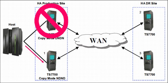
Figure 2-19 Four-cluster grid, one production cluster down, Retain Copy mode disabled
The example in Figure 2-20 shows that the Retain Copy mode is enabled and one of the production clusters is down. In the scenario where the cluster containing the volume to be mounted is down, the host allocates to a device on the other cluster, in this case, Cluster 1. A cross-cluster mount using Cluster 2’s cache occurs, and the original two copies remain. If the volume that is appended to it is changed on Cluster 2 only, Cluster 0 gets a copy of the altered volume when it rejoins the grid.
At this point in time, only one valid copy is available in the grid.

Figure 2-20 Four-cluster grid, one production cluster down, Retain Copy mode enabled
For more information, see the IBM Virtualization Engine TS7700 Series Best Practices - TS7700 Hybrid Grid Usage white paper at the Techdocs website:
Management Class locality to a cluster
Management Classes for the TS7700 Virtualization Engine are created at the management interface associated with a cluster. The same Management Class can be defined differently at each cluster and there are valid reasons for doing so. For example, one of the functions controlled through Management Class is to have a logical volume copied to two separate physical volume pools.
You might want to have two separate physical copies of your logical volumes on one of the clusters and not on the others. Through the management interface associated with the cluster where you want the second copy, specify a secondary pool when defining the Management Class. For the Management Class definition on the other clusters, do not specify a secondary pool. For example, you might want to use the Copy Export function to extract a copy of data from the cluster to take to a DR site.
|
Important: During mount processing, the Copy Consistency Point information that is used for a volume is taken from the Management Class definition for the cluster with which the mount vNode is associated.
|
A best practice is to define the Copy Consistency Point definitions of a Management Class to be the same on each cluster to avoid confusion about where copies will reside. You can devise a scenario in which you define separate Copy Consistency Points for the same Management Class on each of the clusters. In this scenario, the location of copies and when the copies are consistent with the host that created the data will differ, depending on which cluster a mount is processed. In these scenarios, use the Retain Copy mode option. When the Retain Copy mode is enabled against the currently defined Management Class, the previously assigned copy modes are retained independently of the current Management Class definition.
2.3.26 TVC (I/O) selection in a multicluster grid
The TVC associated with one of the clusters in the grid is selected as the I/O TVC for a specific tape mount request during mount request. The vNode is referred to as the mount vNode.
The TS7700 Virtualization Engine filters based on the following elements:
•Cluster availability (offline cluster, cluster in service prep, or degraded will be deselected)
•Mount type:
– Scratch: Deselect all TS7720s with “out of cache” conditions, and remove “no copy” clusters
– Private: Deselect cluster without a valid copy
•Preferences regarding the consistency point, override policies, and families
With these three elements, an obvious favorite can be considered. If not, further filtering occurs where choices are ranked by certain performance criteria, such as cache residency, recall times, network latency, and host workload. The list is ordered favoring the clusters that are thought to provide the optimal performance.
2.3.27 Remote (cross) cluster mounts
A remote (also known as cross) cluster mount is created when the I/O TVC selected is not in the cluster that owns the allocated virtual device. The logical volume is accessed through the grid network using TCP/IP. Each I/O request from the host results in parts of the logical volume moving across the network. Logical volume data movement through the grid is bidirectional and depends on whether the operation is a read or a write. The amount of data transferred depends on many factors, one of which is the data compression ratio provided by the host FICON adapters. To minimize grid bandwidth requirements, only compressed data used or provided by the host is transferred across the network. Read ahead and write buffering are also used to get the maximum from the remote cluster mount.
2.3.28 TVC encryption
From a technical point of view, TVC encryption is a cluster feature. Each cluster can be treated differently from the others in the multicluster grid. There is no difference to a stand-alone cluster.
2.3.29 Logical and stacked volume management
In general, there is no difference to a stand-alone environment.
Each cluster is a separate entity, and you can define different stacked volume pools with different rules on each distributed library.
2.3.30 Secure Data Erase
There is no difference to a stand-alone cluster.
2.3.31 Copy Export
In general, the Copy Export feature has the same functionality as a stand-alone cluster. However, there are additional considerations:
•The Copy Export function is supported on all configurations of the TS7740 Virtualization Engine, including grid configurations. In a grid configuration, each TS7740 Virtualization Engine is considered a separate source TS7740 Virtualization Engine. Only the physical volumes exported from a source TS7740 Virtualization Engine can be used for the recovery of a source TS7740 Virtualization Engine. Physical volumes from more than one source TS7740 Virtualization Engine in a grid configuration cannot be combined for recovery use.
|
Important: Ensure that scheduled Copy Export operations are always executed from the same cluster.
|
•Recovery executed by the client is only to a stand-alone cluster configuration. After recovery, the Grid MES offering can be applied to re-create a grid configuration.
•When a Copy Export operation is initiated, only those logical volumes assigned to the secondary pool specified in the Export List File Volume that are resident on a physical volume of the pool or in the cache of the TS7700 performing the export operation are considered for export. For a Grid configuration, if a logical volume is to be copied to the TS7700 that will perform the Copy Export operation, but that copy had not yet completed when the export is initiated, it will not be included in the current export operation. Ensure that all logical volumes that need to be included are really copied to the cluster where the export process is executed.
•A service from IBM is available to merge a Copy Export set in an existing grid. Talk to your IBM representative.
2.3.32 Encryption of physical tapes
There is no difference to a stand-alone cluster.
2.3.33 Autonomic Ownership Takeover Manager
Autonomic Ownership Takeover Manager (AOTM) is an optional function by which, following a TS7700 Virtualization Engine Cluster failure, one of the methods for ownership takeover is automatically enabled without operator intervention. Enabling AOTM improves data availability levels within the composite library.
AOTM uses the TS3000 System Console (TSSC) associated with each TS7700 Virtualization Engine in a grid to provide an alternate path to check the status of a peer TS7700 Virtualization Engine. Therefore, every TS7700 Virtualization Engine in a grid must be connected to a TSSC. To take advantage of AOTM, you must provide an IP communication path between the TS3000 System Consoles at the cluster sites. Ideally, the AOTM function will use an independent network between locations, but this is not a requirement.
With AOTM, the user configured takeover mode, which is described in 9.2.10, “The Service icon” on page 580, is enabled if normal communication between the clusters is disrupted and the cluster performing the takeover can verify that the other cluster has failed or is otherwise not operational. When a cluster loses communication with another peer cluster, it asks the local TS3000 to which it is attached to communicate with the remote failing cluster’s TS3000 to confirm that the remote TS7700 is actually down. If it is verified that the remote cluster is down, the user configured takeover mode is automatically enabled. If it cannot validate the failure or if the system consoles cannot communicate with each other, AOTM will not enable a takeover mode. In this scenario, ownership takeover mode can only be enabled by an operator through the management interface.
Without AOTM, an operator must determine whether one of the TS7700 Virtualization Engine clusters has failed and then enable one of the ownership takeover modes. This is required to access the logical volumes owned by the failed cluster. It is important that write ownership takeover be enabled only when a cluster has failed, and not when there is only a problem with communication between the TS7700 Virtualization Engine clusters. If it is enabled and the cluster in question continues to operate, data might be modified independently on other clusters, resulting in corruption of data. Although there is no data corruption issue with the read ownership takeover mode, it is possible that the remaining clusters will not have the latest version of the logical volume and present down-level data.
Even if AOTM is not enabled, it is a best practice to configure it. This provides protection from a manual takeover mode being selected when the cluster is actually functional. This additional TS3000 TSSC path is used to determine whether an unavailable cluster is still operational or not. This path is used to prevent the user from forcing a cluster online when it must not be, or enabling a takeover mode that can result in dual volume use.
2.3.34 Selective Write Protect for disaster recovery testing
This function allows clients to emulate disaster recovery events by running test jobs at a DR location within a TS7700 grid configuration and only allowing volumes within specific categories to be manipulated by the test application. This prevents any changes to production-written data. This is accomplished by excluding up to 16 categories from the cluster’s write protect enablement. When a cluster is write protect-enabled, all volumes that are protected cannot be modified or have their category or storage construct names modified. Like in the TS7700 write protect setting, the option is at the cluster scope and configured through the management interface. Settings are persistent. Also, the new function allows for any volume assigned to one of the categories contained within the configured list to be excluded from the general cluster’s write protect state. The volumes assigned to the excluded categories can be written to or have their attributes modified. In addition, those scratch categories not excluded can optionally have their Fast Ready characteristics ignored, including Delete Expire and hold processing, allowing the DR test to mount volumes as private that the production environment has since returned to scratch (they will be accessed as read-only).
One exception to the write protect is those volumes in the insert category. To allow a volume to be moved from the insert category to a write protect-excluded category, the source category of insert cannot be write-protected. Therefore, the insert category is always a member of the excluded categories.
Be sure that you have enough scratch space when Expire Hold processing is enabled to prevent the reuse of production scratched volumes when planning for a DR test. Suspending the volumes’ Return-to-Scratch processing for the duration of the DR test is also advisable.
Because selective write protect is a cluster-wide function, separated DR drills can be conducted simultaneously within one multicluster grid, with each cluster having its own independent client-configured settings.
For more details, see 11.9.4, “Protecting production volumes with Selective Write Protect” on page 818.
2.3.35 Service preparation mode
The transition of a cluster into service mode is called service prep. Service prep allows a cluster to be gracefully and temporarily removed as an active member of the grid. The remaining sites can acquire ownership of the volumes while the site is away from the grid. If a volume owned by the service cluster is not accessed during the outage, ownership is retained by the original cluster. Operations that target the distributed library entering service are completed by the site going into service before transition to service completes. Other distributed libraries within the composite library will remain available. The host device addresses associated with the site in service send Device State Change alerts to the host, allowing those logical devices associated with the service preparation cluster to enter the pending offline state.
When service prep completes and the cluster enters service mode, nodes at the site in service mode remain online. However, the nodes are prevented from communicating with other sites. This stoppage allows service personnel to perform maintenance tasks on the site’s nodes, run hardware diagnostics, and so on, without affecting other sites.
Only one service prep can occur within a composite library at a time. If a second service prep is attempted at the same time, it will fail. After service prep is complete and the cluster is in service mode, another cluster can be placed in service prep.
A site in service prep automatically cancels and reverts back to an ONLINE state if any ONLINE peer in the grid experiences an unexpected outage. The last ONLINE cluster in a multicluster configuration cannot enter the service prep state. This restriction includes a stand-alone cluster. Service prep can be canceled using the management interface or by the IBM SSR at the end of the maintenance procedure. Canceling service prep returns the subsystem to a normal state.
2.3.36 Service mode
After a cluster completes service prep and enters service mode, it remains in this state. The cluster must be explicitly taken out of service mode by the operator or the IBM SSR.
In smaller grid configurations, we suggest that you only put a single cluster into service at a time in order to retain the redundancy of the grid. This, of course, is only a suggestion and does not prevent the action from taking place, if necessary.
|
Note: If you have more than one cluster in service mode, any of the servicing clusters cannot fully enter the ONLINE state until all clusters in service have attempted to come online. Therefore, the best practice is to have all clusters cancel service at roughly the same time. An SSR has the ability to override this behavior in special use cases.
|
2.4 Grid configuration examples
Several grid configuration examples are provided. We describe the requirements for high availability (HA) and DR planning.
2.4.1 Homogeneous versus hybrid grid configuration
Homogeneous configurations contain either only TS7720 or only TS7740. If you have an intermix of both TS7720s and TS7740s, it is a hybrid configuration.
Consider the following information when you choose whether a TS7720, TS7740, or a mixture of the two types is appropriate.
Requirement: Fast read response times, large amounts of reads
Whenever your environment needs to process a large number of reads in a certain amount of time or it needs fast response times, the TS7720 is the best choice. The TS7740 is susceptible to disk cache misses, resulting in a recall, making the TS7740 not optimal for workloads needing the highest cache hit read percentages.
Although TS7720 configurations can store over 600 TB of post-compressed content in disk cache, your capacity needs might be far too large, especially when a large portion of your workload does not demand the highest read hit percentage. This is when the introduction of a TS7740 makes sense.
Requirement: No physical tape or dark site
Some clients are looking to completely eliminate physical tape from one or more data center locations. The TS7720 or a hybrid configuration supports these requirements. Remember that the complete elimination of physical tape might not be the ideal configuration because the benefits of both physical tape and deep disk cache can be achieved with hybrid configurations.
Requirement: Big data
The TS7740 is attached to a TS3500 library and therefore provides the ability to store multiple petabytes of data while still supporting writes at disk speeds and read hit ratios up to 90% for many workloads.
Depending on the size of your TS3500 tape library (the number of library frames and the capacity of the tape cartridges being used), you can store more than 40 PT of data.
Requirement: Offsite vault of data for DR purposes with Copy Export
Some clients require an additional copy on physical tape, require a physical tape to be stored in a vault, or depend on the export of physical tape for their DR needs. For these accounts, the TS7740 is ideal.
Requirement: Workload movement with Copy Export
In specific use cases, the data associated with one or more workloads must be moved from one grid configuration to another without the use of TCP/IP. Physical tape and TS7740 Copy Export with merge (available as a service offering) provide this capability.
2.4.2 Planning for high availability or disaster recovery in limited distances
In many HA configurations, two TS7700 Virtualization Engine clusters are located within metro distance of each other. They are in one of the following situations:
•The same data center within the same room
•The same data center, located in different rooms
•Separated data centers, located on a campus
•Separated data centers, located at a distance in the same metropolitan area
These clusters are connected through a local area network. If one of them becomes unavailable because it failed, is being serviced, or is being updated, data can be accessed through the other TS7700 Virtualization Engine Cluster until the unavailable cluster is available. The assumption is that continued access to data is critical, and no single point of failure, repair, or upgrade can affect the availability of data.
For these configurations, the multicluster grid can act as both an HA and DR configuration that assumes that all host and disk operations can recover at the metro distant location. But, metro distances might not be ideal for DR, because some disasters can affect an entire metro region. In this situation, a third location is ideal.
Configuring for high availability or metro distance
As part of planning a TS7700 Virtualization Engine Grid configuration to implement this solution, consider the following information:
•Plan for the virtual device addresses in both clusters to be configured to the local hosts.
•Plan a redundant FICON attachment of both sites (an extender that is longer than 10 km (6.2 miles) for the FICON connections is suggested)
•Determine the appropriate Copy Consistency Points for the workloads that require the highest RPO, use Sync, or use RUN. For those workloads that are less critical, use deferred replication.
•Design and code the DFSMS ACS routines that point to a TS7700 Management Class with the appropriate Copy Consistency Point definitions.
•Ensure that the AOTM is configured for an automated logical volume ownership takeover in case a cluster becomes unexpectedly unavailable within the grid configuration. Alternatively, prepare written instructions for the operators that describe how to perform the ownership takeover manually, if needed. See 2.3.33, “Autonomic Ownership Takeover Manager” on page 77.
2.4.3 Disaster recovery capabilities in a remote data center
A mechanical problem or human error event can make the local site’s TS7700 Virtualization Engine Cluster unavailable. Therefore, one or more additional grid members can be introduced, separated by larger distances, to provide business continuance or DR functionality.
Depending on the distance to your DR data center, consider connecting your grid members in the DR location to the host in the local site.
No FICON attachment of the remote grid members
In this case, the only connection between the local site and the DR site is the grid network. There is no host connectivity between the local hosts and the DR site’s TS7700 Virtualization Engine.
FICON attachment of the remote grid members
For distances longer than 10 km (6.2 miles), you need to introduce dense wavelength division multiplexing (DWDM) or channel extension equipment.
Depending on the distance (latency), there might be a difference in read or write performance compared to the virtual devices on the local TS7700 Virtualization Engine Cluster:
•Depending on the distance separating the sites.
•If the local TS7700 Virtualization Engine Cluster becomes unavailable, use this remote access to continue your operations by using a remote TS7700 Virtualization Engine Cluster.
•If performance differences are a concern, consider using only the virtual device addresses in a remote TS7700 Virtualization Engine Cluster when the local TS7700 Virtualization Engine is unavailable. If these differences are an important consideration, in addition to the ownership takeover procedure, you need to provide operator procedures to vary the virtual devices in a remote TS7700 Virtualization Engine from online to offline.
As part of planning a TS7700 Virtualization Engine grid configuration to implement this solution, consider the following information:
•Plan for the necessary WAN infrastructure and bandwidth to meet the copy requirements that you need. You generally need more bandwidth if you are primarily using a Copy Consistency Point of SYNC or RUN, because any delays in copy time caused by bandwidth limitations can result in an elongation of job run times. If you have limited bandwidth available between sites, copy critical data with a consistency point of SYNC or RUN, with the rest of the data using the Deferred Copy Consistency Point. Consider introducing cluster families (only for three or more cluster grids).
•Plan for host connectivity at your DR site with sufficient resources to perform your critical workloads.
•Design and code the DFSMS ACS routines that point to the appropriate TS7700 Management Class constructs to control the data that gets copied and by which Copy Consistency Point.
•Prepare procedures that your operators execute in the event that the local site becomes unusable. The procedures include tasks, such as bringing up the DR host, varying the virtual drives online, and placing the DR TS7700 Virtualization Engine Cluster in one of the ownership takeover modes. Even if you have AOTM configured, prepare the procedure for a manual takeover.
2.4.4 Configuration examples
Next, we provide examples that are installed in the field, depending on the requirements of the clients.
Example 1: Two-cluster grid
With a two-cluster grid, you can configure the grid for DR, HA, or both.
This example is a two-site scenario, located in a 10 km (6.2 miles) distance. Although the customer has a need for big data, and read processes are limited, two TS7740 were installed. One TS7740 was installed in each data center.
Because of the limited distance, both clusters are FICON attached to each host.
The client chooses to use Copy Export to store a third copy of the data in an offsite vault. See Figure 2-21.

Figure 2-21 Two-cluster grid
Example 2: Three-cluster grid in two locations
In this example (Figure 2-22 on page 83), one of the data center locations has several departments. The grid and the hosts are spread across the different departments. For DR purposes, the client introduced a remote site, where the third TS7740 is installed.
The client runs a lot of OAM and HSM workloads, so the large cache of the TS7720 provides the necessary bandwidth and response times. Also, the client wanted to have a third copy on a physical tape, which is provided by the TS7740 in the remote location.

Figure 2-22 Three-cluster grid in two locations
Example 3: Three-cluster grid in three locations
This example is the same as configuration example 2. However, in this case, the two TS7720s and the attached hosts are spread across two data centers that are located at a distance that is beyond 10 km (6.2 miles). Again, the third location is a data-only store. See Figure 2-23 on page 84.
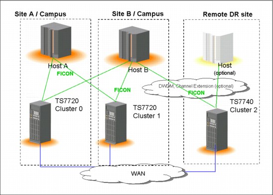
Figure 2-23 Three-cluster grid in three locations
Example 4: Four-cluster grid in three locations
This configuration, Figure 2-24 on page 85, shows the configuration after a merge of existing grids. Before the merge, the grids were only spread across 10 km (6.2 miles). The client’s requirements changed. The client needed a third copy in a data center at a longer distance.
By merging environments, the client can address the requirements for DR and still use the existing environment.

Figure 2-24 Four-cluster grid in three locations
2.5 TS7700 Virtualization Engine hardware components
TS7700 Virtualization Engine Release 3.0 supports the powerful 3957 V07/VEB control unit that was introduced with R2.0. This control unit is based on an IBM System POWER7 processor-based server with new I/O expansion drawers and PCI Express adapters. The new hardware platform significantly enhances the performance capabilities of the subsystem. It also makes room for future functions and enhancements.
We describe the hardware components that are part of the TS7700 Virtualization Engine. These components include the TS7720 Virtualization Engine disk-only solution and the TS7740 Virtualization Engine with its TS3500 tape library.
The TS7720 Virtualization Engine is available in one of two frame configurations:
•An IBM 3952 Tape Base Frame, which houses the following components:
– One TS7720 Virtualization Engine server
– Two TS7700 Server Expansion Unit I/O drawers (Primary and Alternate)
– One TS7720 Virtualization Engine Encryption Capable 3956-CS9 Cache Controller with up to nine optional TS7720 Virtualization Engine Encryption Capable 3956-XS9 Cache Expansion Drawers
– Two Ethernet switches
– Optionally, one TS3000 System Console (TSSC)
•An optional IBM 3952 Storage Expansion Frame, which houses the following components:
– One TS7720 Virtualization Engine Encryption Capable 3956-CS9 cache controller
– Up to 15 optional TS7720 Virtualization Engine Encryption Capable 3956- XS9 Cache Expansion Drawers
The TS7740 Virtualization Engine is available in the following configuration:
•An IBM 3952 Tape Frame, which houses the following components:
– One TS7740 Virtualization Engine server
– One TS7740 Virtualization Engine Encryption Capable 3956-CC9 Cache Controller with zero, one, or two TS7740 Virtualization Engine Encryption Capable 3956-CX9 Cache Expansion Drawers
– Two Ethernet switches
•Optionally, one TS3000 System Console (TSSC)
•One TS3500 Tape Library with 4 - 16 IBM 3592 Tape Drives and two Fibre Channel switches
2.5.1 Common components for the TS7720 Virtualization Engine and TS7740 Virtualization Engine models
The following components are common for both models of the TS7700 Virtualization Engine.
IBM 3952 Tape Base Frame
The IBM 3952 Tape Base Frame Model F05 is a frame that provides up to 36U (rack units or EIA units) of usable space. The rack units contain the components of the defined tape solution. The 3952 Tape Base Frame is not a general-purpose frame. It is designed to contain only the components of specific tape offerings, such as the TS7740 Virtualization Engine or TS7720 Virtualization Engine. Only components of one solution family can be installed in a 3952 Tape Base Frame. The 3952 Tape Frame contains a power supply and offers an optional Dual AC Power Supply feature.
In a TS7700 Virtualization Engine configuration, the 3952 Tape Base Frame is used for the installation of the following components:
•The TS7700 Virtualization Engine Server
•Two TS7700 Server Expansion Unit I/O Drawers (Primary and Alternate)
•The TS7700 Virtualization Engine Cache Controller
•The TS7700 Virtualization Engine Cache Expansion Drawers
•Two Ethernet switches
•Optionally, the TS3000 System Console
These components are described in detail for the TS7700 Virtualization Engine specific models in the following sections.
TS3000 System Console (TSSC)
The TS3000 System Console (TSSC) is a required component for the TS7700 Virtualization Engine. It can be a new console or an existing TSSC.
If using a new TSSC, install it in the TS7700 Virtualization Engine 3952-F05 Base Frame or an existing rack.
When a TSSC is ordered with a TS7700 Virtualization Engine, it can be preinstalled in the 3952-F05 frame. The TSSC is a 1U server that includes a keyboard, display, mouse, and one 16-port Ethernet switch.
Ethernet switches
Previous Ethernet routers are replaced by new 1 Gb Ethernet switches in all new TS7700 Virtualization Engines. The new switches (two for redundancy) are used in the TS7700 internal network communications.
The communications to the external network use a set of dedicated Ethernet ports. Communications were previously handled by the routers as management interface addresses and in encryption key management.
Internal network communications (interconnecting TS7700 new switches, TSSC, Disk Cache System, and TS3500 when present) use their own set of Ethernet ports.
The virtual IP address previously provided by the router’s translation capability is now implemented by virtual IP address (VIPA) technology.
When replacing an existing TS7700 Virtualization Engine Model V06/VEA with a new V07/VEB model, the old routers stay in place. They are, however, reconfigured and used solely as regular switches. The existing external network connections will be reconfigured and connected directly to the new V07/VEB server.
Figure 2-25 shows the new 1 Gb switch and the old Ethernet router for reference.

Figure 2-25 New switch (top) and old router (bottom)
TS7700 Virtualization Engine grid adapters
The connection paths between multiple TS7700 Virtualization Engines in a grid configuration are the two grid adapters in the I/O expansion drawers.
With the TS7700 Virtualization Engine 3957-V07/VEB server, the grid adapters have been moved to slot 1 of the expansion drawers. The grid adapters for the V06/VEA engine are plugged into slots 4 and 5. The dual-ported 1 Gbps Ethernet adapters can be copper RJ45 or optical fiber (shortwave). These optical adapters have an LC duplex connector.
For improved bandwidth and additional availability, TS7700 Virtualization Engine R2.0 now supports two or four 1-Gb links. Feature Code 1034 (FC1034) is needed to enable the second connection port in each grid adapter. This port can be either fiber shortwave (SW) or copper. With the new V07/VEB server hardware platform, there is a choice of two long-wave (LW) single-ported Optical Ethernet adapters (FC1035) for two 10-Gb links. Your network infrastructure needs to support 10 Gbps for the LW option.
The Ethernet adapters cannot be intermixed within a cluster. Both grid adapters in a TS7700 Virtualization Engine must be the same feature code.
Expanded memory
This feature was introduced by TS7700 Virtualization Engine Release 1.7 code. It provided capabilities to support additional physical memory, upgrading server memory from 8 GB to
16 GB. It only applies to already installed 3957 servers, Model V06/VEA, manufactured prior to R1.7 systems. New machines (3957-V06/VEA) manufactured after R1.7 ship with 16 GB memory installed at the plant.
16 GB. It only applies to already installed 3957 servers, Model V06/VEA, manufactured prior to R1.7 systems. New machines (3957-V06/VEA) manufactured after R1.7 ship with 16 GB memory installed at the plant.
TS7700 Virtualization Engine Licensed Internal Code R2.0, R2.1, and R3.0 require 16 GB of internal memory.
If you have 3957 model V06/VEA servers with 8 GB and plan to upgrade to R2.0 or higher, you need to order Feature Code 3461 (Memory Upgrade). Work with your IBM SSR to better understand the prerequisites.
|
Important: Release 3.0 is not supported on 3956-V06-based TS7740s with 3956-CC6 Cache Controllers.
|
The new 3957-V07/VEB server features 16 GB of physical memory in its basic configuration.
TS7700 Virtualization Engine Server (3957-V07/VEB)
The engine server consists of an IBM System POWER7 processor-based server and two new expansion drawers for I/O adapters. This replaces the original IBM POWER® 5 ++ and the I/O drawers from the V06/VEA version. The TS7700 Virtualization Engine Server controls virtualization processes such as host connectivity and device virtualization. It also controls the internal hierarchical storage management (HSM) functions for logical volumes and replication.
Figure 2-26 shows the front view of the new TS7700 Virtualization Engine Server 3957-V07/VEB.

Figure 2-26 TS7700 Virtualization Engine Server (front view)
The TS7700 Virtualization Engine Server V07/VEB offers the following features:
•Rack-mount (4U) configuration.
•One 3.0 Ghz 8-core processor card.
•16 GB of 1066 MHz error checking and correcting (ECC) memory: The 3957-V07/VEB server provides scalable processing power and performance through pluggable processor and memory cards. Fully configured, it can increase to 32 processors and 256 GB of dynamic device reconfiguration 3 (DDR3) physical memory. Therefore, you can increase processing power and capacity on demand. This makes it ready for future enhancements.
•Eight small form factor (SFF) DASD: Four disk drives are assigned to an internal serial-attached SCSI (SAS) controller. The other four disk drives are assigned to an external SAS adapter, providing redundancy.
•The following integrated features:
– Service processor
– Quad-port 10/100/1000 Mb Ethernet
– IBM EnergyScale™ technology
– Hot-swap capability and redundant cooling
– Two system (serial) ports
– Two HMC ports
– Two system power control network (SPCN) ports
– One slim bay for a DVD-RAM
•Five hot-swap slots:
– Two PCIe x8 slots, short card length (slots 1 and 2)
– One PCIe x8 slot, full card length (slot 3)
– Two PCI-X DDR slots, full card length (slots 4 and 5)
The hot-swap capability is only for replacing an existing adapter with another of the same type. It is not available when changing adapter types in a machine upgrade or change.
•SAS hard disk drives: TS7700 uses eight disk drives. Four disks mirror one SAS adapter, and the other four backup drives are assigned to a separate SAS adapter.
•A SAS card is used for the mirroring and SAS controller redundancy. It has an external cable for accessing the mirrored disks.
Each new Expansion Unit I/O Adapter Drawer offers six additional PCI-X or PCI Express adapter slots:
•One or two 4-Gb FICON adapters per I/O Expansion Drawer, total of two or four FICON adapters per cluster. Adapters can work at 1, 2, or 4 GB.
•Grid Ethernet card (PCI Express)
•Fibre Channel to disk cache (PCI Express)
•Tape connection card in a TS7740 or Expansion frame in a TS7720 - Fibre Channel PCI Express
2.5.2 TS7720 Virtualization Engine components
The TS7720 Virtualization Engine is the latest member of the TS7700 Virtualization Engine family. The TS7720 Virtualization Engine is a disk-only Virtualization Engine. It provides most of the benefits of the TS7740 Virtualization Engine without physical tape attachment. The TS7720 Virtualization Engine can be used to write tape data that does not need to be copied to physical tape. This allows access to the data from the Virtualization Engine Cache until the data expires.
The TS7720 Virtualization Engine is configured with different server models and different disk cache models than the TS7740 Virtualization Engine. Field installation of cache models CX7/XS7 to fill existing base and expansion frames is supported until it is withdrawn in December 2013. An RPQ for a second expansion frame with CS8/XS7 was available through at least the first half of 2013.
The latest TS7720 Virtualization Engine Release 3.0 consists of a 3952 Model F05 Encryption Capable Base Frame and an optional 3952 Model F05 Encryption Capable Storage Expansion Frame.
Full disk encryption requires all disk cache drawers to support encryption. FC5272 enables full disk encryption on the VEB. FC7404 is needed to enable full disk encryption on each cache drawer. Full disk encryption cannot be disabled. Clients must consider having a copy of the encryption keys on DVD as a backup.
The 3952 Model F05 Tape Base Frame houses the following components:
•One TS7720 Virtualization Engine Server, 3957 Model VEB
•Two TS7700 Expansion Unit I/O Drawers (Primary and Alternate)
•One TS7720 Virtualization Engine Encryption Capable SAS Cache Controller 3956-CS9. The controller has zero to nine TS7720 Virtualization Engine Encryption Capable SAS 3956- XS9 Cache Expansion Drawers.
•Two Ethernet switches
The 3952 Model F05 Storage Expansion Frame houses one TS7720 Virtualization Engine Encryption Capable SAS Cache Controller 3956-CS9. Each controller can have zero to fifteen TS7720 Virtualization Engine Encryption Capable SAS 3956-XS9 Cache Expansion Drawers.
Each TS7720 Virtualization Engine SAS Cache Controller, 3956 Model CS9 using 3-TB drives, provides approximately 23.86 TB of capacity after RAID 6 formatting. The TS7720 Virtualization Engine SAS Cache Drawers, 3956 Model XS9 using 3-TB drives, provides approximately 24 TB of capacity after RAID 6 formatting. The TS7720 uses global spares, allowing all expansion drawers to share a common set of spares in the RAID 6 configuration. The base frame cache controller can have a separate capacity than the other two controllers in the expansion frame. This configuration depends on characteristics, such as the number of the expansion drawers in the expansion frame and disk size in the basic frame.
Using 3 TB disk drives, the maximum configurable capacity of the TS7720 Virtualization Engine at R3.0 with the 3952 Model F05 Storage Expansion Frame is 623 TB of data before compression.
Figure 2-27 shows the TS7720 Virtualization Engine Base Frame components.
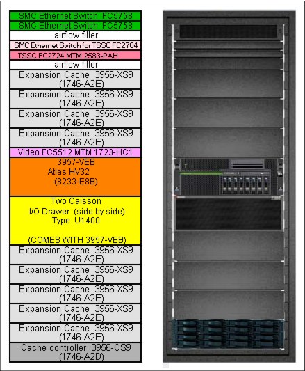
Figure 2-27 TS7720 Virtualization Engine Base Frame components
Figure 2-28 shows the TS7720 Virtualization Engine Expansion Frame components.
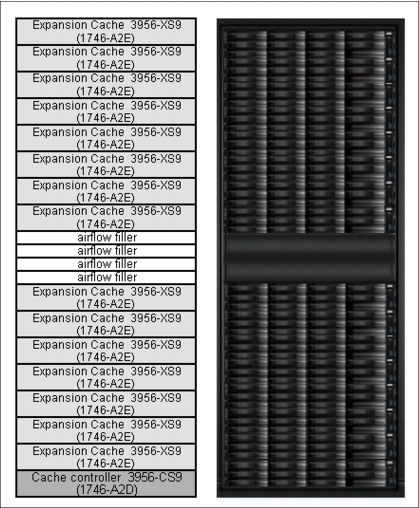
Figure 2-28 TS7720 Virtualization Engine Expansion Frame components
TS7720 Virtualization Engine Cache Controller (3956-CS9)
The TS7720 Virtualization Engine Encryption Capable Cache Controller, 3956 Model CS9, is a self-contained 2U enclosure. It mounts in the 3952 Tape Base Frame and the optional 3952 Storage Expansion Frame. Figure 2-29 shows the TS7720 Virtualization Engine Cache Controller from the front (left side) and rear (right side).

Figure 2-29 TS7720 Virtualization Engine Encryption Capable Cache Controller, 3956-CS9 (front and rear views)
The TS7720 Virtualization Engine Cache Controller provides RAID 6 protection for virtual volume disk storage, allowing fast retrieval of data from cache. The TS7720 Virtualization Engine Cache Controller offers the following features:
•Two 8 Gbps Fibre Channel processor cards
•Two battery backup units (one for each processor card)
•Two power supplies with embedded enclosure cooling units
•12 DDMs, each with a storage capacity of 3 TB, for a usable storage capacity of 23.86 TB
•Configurations support one or two TS7720 Virtualization Engine Cache Controllers:
– All configurations provide one TS7720 Virtualization Engine Cache Controller in the 3952 Tape Base Frame. The 3952 Tape Base Frame can have zero to nine TS7720 Virtualization Engine Encryption Capable SAS Cache Drawers, 3956 Model XS9.
– All configurations with the optional 3952 Storage Expansion Frame provide one additional TS7720 Virtualization Engine Encryption Capable Cache Controller, 3956 Model CS9. The 3952 Storage Expansion Frame can have zero to fifteen TS7720 Virtualization Engine Encryption Capable SAS Cache Drawers, 3956 Model XS9.
TS7720 Virtualization Engine Cache Drawer (3956-XS9)
The TS7720 Virtualization Engine Encryption Capable Cache Drawer is a self-contained 2U enclosure. It mounts in the 3952 Tape Base Frame and in the optional 3952 Storage Expansion Frame. Figure 2-30 shows the TS7720 Virtualization Engine Cache Drawer from the front (left side) and rear (right side). It offers attachment to the TS7720 Virtualization Engine Encryption Capable Cache Controller.

Figure 2-30 TS7720 Virtualization Engine Encryption Capable Cache Drawer (front and rear views)
The TS7720 Virtualization Engine Cache Drawer expands the capacity of the TS7720 Virtualization Engine Cache Controller by providing additional RAID 6-protected disk storage. Each TS7720 Virtualization Engine Cache Drawer offers the following features:
•Two Fibre Channel processor cards
•Two power supplies with embedded enclosure cooling units
•Eleven DDMs, each with a storage capacity of 3 TB, for a usable capacity of 24 TB per drawer
2.5.3 TS7740 Virtualization Engine components
The TS7740 combines the TS7700 Virtualization Engine with a tape library to form a virtual tape subsystem in order to write to physical tape. TS7700 Virtualization Engine Release 3.0 supports the TS7740 Virtualization Engine Encryption Capable Cache Controller, 3956 Model CC9. This disk cache model includes twenty-two 600 GB SAS hard disk drives (HDDs). These HDDs provide approximately 9.45 TB of usable capacity after RAID 6 formatting. Optional Encryption Capable Cache Drawers Model 3956-CX9 can be added. This drawer includes twenty- two 600 GB SAS HDDs with an approximate 9.58 TB of usable capacity after RAID 6 formatting.
Full disk encryption requires all disk cache drawers to support encryption. FC5272 enables full disk encryption on the V07. FC7404 is needed to enable full disk encryption on each cache drawer. Full disk encryption cannot be disabled. Clients must consider having a copy of encryption keys on DVD as a backup.
Release 3.0 is not supported on 3956-V06-based TS7740s with the 3956-CC6 Cache Controllers.
New TS7740 Virtualization Engine Release 3.0 plant-built configurations include these components:
•One TS7740 Virtualization Engine Server, 3957 Model V07.
•One TS7740 Virtualization Engine Encryption Capable SAS 3956-CC9 Cache Controller.
•The controller has zero, one, or two TS7740 Virtualization Engine Encryption Capable SAS 3956-CX9 Cache Expansion Drawers.
The total usable capacity of a TS7740 Virtualization Engine with one 3956 Model CC9 and two 3956 Model CX9s is approximately 28.61 TB before compression.
The Model CX9s can be installed at the plant or in an existing TS7740 Virtualization Engine.
Figure 2-31 shows a summary of TS7740 Virtualization Engine components.

Figure 2-31 Virtualization Engine TS7740 components
TS7740 Virtualization Engine Cache Controller (3956-CC9)
The TS7740 Virtualization Engine Encryption Capable Cache Controller is a self-contained 2U enclosure that mounts in the 3952 Tape Frame.
Figure 2-32 shows the front and rear views of the TS7740 Virtualization Engine Model CC9 Encryption Capable Cache Controller.

Figure 2-32 TS7740 Virtualization Engine Encryption Capable Cache Controller (front and rear views)
Figure 2-33 shows a diagram of the rear view.

Figure 2-33 TS7740 Virtualization Engine Encryption Capable Cache Controller (rear view)
The TS7740 Virtualization Engine Encryption Capable Cache Controller provides
RAID 6-protected virtual volume disk storage. This storage temporarily holds data from the host before writing it to physical tape. It then caches the data to allow fast retrieval from the disk. The TS7740 Virtualization Engine Cache Controller offers the following features:
RAID 6-protected virtual volume disk storage. This storage temporarily holds data from the host before writing it to physical tape. It then caches the data to allow fast retrieval from the disk. The TS7740 Virtualization Engine Cache Controller offers the following features:
•Two 8 Gbps Fibre Channel processor cards
•Two battery backup units (one for each processor card)
•Two power supplies with embedded enclosure cooling units
•Twenty-two DDMs, each possessing 600 GB of storage capacity, for a usable capacity of 9.45 TB
•Optional attachment to one or two TS7740 Virtualization Engine Encryption Capable Cache Drawers, Model 3956-CX9
TS7740 Virtualization Engine Cache Drawers (3956-CX9)
The TS7740 Virtualization Engine Encryption Capable Cache Drawer is a self-contained 2U enclosure that mounts in the 3952 Tape Frame.
Figure 2-34 shows the front view and the rear view of the TS7740 Virtualization Engine Encryption Capable Model CX9 Cache Drawer.

Figure 2-34 TS7740 Virtualization Engine Encryption Capable Cache Drawer (front and rear views)
The TS7740 Virtualization Engine Encryption Capable Cache Drawer expands the capacity of the TS7740 Virtualization Engine Cache Controller by providing additional RAID 6 disk storage. Each TS7740 Virtualization Engine Cache Drawer offers the following features:
•Two Fibre Channel processor cards
•Two power supplies with embedded enclosure cooling units
•22 DDMs, each with 600 GB of storage capacity, for a total usable capacity of 9.58 TB per drawer
•Attachment to the TS7740 Virtualization Engine Encryption Capable Cache Controller, Model 3956-CC9
TS7740 Virtualization Engine Tape Library attachments, drives, and media
In a TS7740 Virtualization Engine configuration, the TS7740 Virtualization Engine is used in conjunction with an attached tape library. The TS7740 must have its own logical partition (LPAR) within the TS3500 Tape Library, with dedicated tape drives and tape cartridges.
Tape libraries
The TS3500 Tape Library is the only library supported with TS7740 Virtualization Engine Release 2.0 Licensed Internal Code and later. To support a TS7740, the TS3500 Tape Library must include a frame model L23 or D23 that is equipped with TS7740 back-end fiber switches.
|
Remember: Each TS7740 Virtualization Engine requires two separate Fibre Channel switches for redundancy.
|
The TS7740 Virtualization Engine Release 3.0 supports 4-Gb and 8-Gb Fibre Channel switches. Feature Code 4872 provides two TS7700 4-Gb Fibre Channel back-end switches. Feature Code 4875 provides one 8-Gb Fibre Channel. The TS7740 requires two switches per frame.
Tape drives
The TS7740 Virtualization Engine supports the following tape drives inside a TS3500 Tape Library:
•IBM 3592 Model J1A Tape Drive: However, for maximum benefit from the TS7740 Virtualization Engine, use more recent generations of the 3592 Tape Drive. The 3592 Model J1A Tape Drives cannot be intermixed with TS1130 Tape Drives or TS1140 Tape Drives. The 3592 Model J1A Tape Drives can be intermixed with TS1120 Tape Drives. If the TS1120s are intermixed, they must be set to J1A emulation mode.
•TS1120 Tape Drive (native mode or emulating 3592-J1A Tape Drives): Tape drive types cannot be intermixed except for 3592-J1A Tape Drives and TS1120 Tape Drives operating in 3592-J1A emulation mode.
•TS1130 Tape Drive: TS7740 Virtualization Engine Release 1.6 and later include support for TS1130 Tape Drives. When a TS1130 Tape Drive is attached to a TS7740 Virtualization Engine, all attached drives must be TS1130 Tape Drives. Intermixing is not supported with 3592-J1A and TS1120 Tape Drives. TS1130 Tape Drives can read data written by either of the prior generation 3592 Tape Drives. Tapes written in E05 format are appended to in E05 format. The first write to supported tapes are written in the E06 format.
If TS1130 Tape Drives are detected and other generation 3592 Tape Drives are also detected, the TS1130 Tape Drives are not configured.
•TS1140 Tape Drive (3592 Model E07) is the fourth generation of the 3592 Tape Drives. This encryption capable drive reads and writes in EFMT4 format, with 2176 tracks, using 32 read/write channels. (The TS1120 and TS1130 only have 16 read/write channels, and Model J1A has eight read/write channels.)
All these advantages allow TS1140 to reach a 250 MB/sec of data transfer rate and 4 TB of native capacity on a a JC cartridge. The E07 can read JA/JJ media written in J1A format (JA and JJ media are sunset with E07 drives) and E05 format. Also, 3592-E07 can read and write E06 format. No emulation mode is supported with the TS1140.
The TS1140 cannot be intermixed with any other model of the 3592 drives in the same TS7740.
The TS1140 attached to the TS7740 only supports JB, JC, and JK media for write.
Tapes are written in E07 format when writing from BOT or in E06 format when appending to a E06 format tape. Using Copy Export, you can specify either E06 or E07 formats for the output tape.
Tapes are written in E07 format when writing from BOT or in E06 format when appending to a E06 format tape. Using Copy Export, you can specify either E06 or E07 formats for the output tape.
If FC9900 is installed or if you plan to use tape drive encryption with the TS7740 Virtualization Engine, ensure that the installed tape drives support encryption and are enabled for System-Managed Encryption using the TS3500 Library Specialist. By default, TS1130 and TS1140 Tape Drives are encryption-capable. TS1120 Tape Drives with the encryption module are also encryption-capable. Encryption is not supported on 3592 Model J1A Tape Drives.
For more information, see 2.2.24, “Encryption of physical tapes” on page 45 and 4.6.8, “Planning for tape encryption in the TS7740 Virtualization Engine” on page 171.
Tape media
The TS7740 Virtualization Engine supports the following types of media:
•3592 Tape Cartridge (JA)
•3592 Expanded Capacity Cartridge (JB)
•3592 Advanced Tape Cartridge (JC)
•3592 Economy Tape Cartridge (JJ)
•3592 Economy Advanced Tape Cartridge (JK) media.
WORM cartridges (JW, JR, JX, and JY) are not supported. Scaling is not supported.
Not all media types are supported by all drive models. Check Table 2-2 for your configuration.
Table 2-2 Summary of the 3592 Tape Drive models and characteristics versus the supported media and capacity
|
3592 drive type
|
Supported media type
|
Encryption support
|
Capacity
|
Data rate
|
|
TS1140 Tape Drive
(3592-E07 Tape Drive)
|
JB
JC
JK
Media read only:
JA
JJ
|
Yes (IBM Tivoli Key Lifecycle Manager or
IBM Security Key Lifecycle Manager only)
|
1.6 TB (JB native)
4.0 TB (JC native)
500 GB (JK native)
4.0 TB (maximum all)
|
250 MB/s
|
|
TS1130 Tape Drive
(3592-EU6 or 3592-E06 tape drive)
|
JA
JB
JJ
|
Yes
|
640 GB (JA native)
1.0 TB (JB native)
128 GB (JJ native)
1.0 TB (maximum all)
|
160 MB/s
|
|
TS1120 Tape Drive
(3592-E05 Tape Drive)
|
JA
JB
JJ
|
Yes
|
500 GB (JA native)
700 GB (JB native)
100 GB (JJ native)
700 GB (maximum all)
|
100 MB/s
|
|
3592-J1A
|
JA
JJ
|
No
|
300 GB (JA native)
60 GB (JJ native)
300 GB (maximum all)
|
40 MB/s
|
The tape media has the following characteristics:
•Use of JB tape cartridges with TS1120 Tape Drives is supported only when operating in native capacity mode. Use of JB tape cartridges is supported with TS1130 Tape Drives.
•When TS1120 Tape Drives operating in native mode are replaced with TS1130 Tape Drives, additional data written on the 3592-E05 formatted tapes will be appended until they are full. As the active data on the E05 formatted tapes gets reclaimed or expired, the tape goes back to the scratch pool. On the next write, the tape will be reformatted to the 3592-E06 data format.
•TS1120 Tape Drives can operate in native E05 mode or in 3592-J1A emulation mode. However, all 3592 Tape Drives associated with the TS7700 Virtualization Engine must be TS1120 Tape Drives to operate in native E05 mode. To use TS1120 Tape Drives in native E05 mode, all attached drives must be set to E05 native mode. To use TS1120 Tape Drives in J1A emulation mode, all attached drives must be set to J1A emulation mode. The capacity of the tape media and performance will be the same as the capacity and performance specified for a 3592-J1A.
•When 3592-J1A drives (or TS1120 Tape Drives in J1A emulation mode) are replaced with TS1130 Tape Drives, the TS7740 Virtualization Engine marks the J1A formatted tapes with a status of active data FULL. By marking these tapes full, the TS7740 Virtualization Engine does not append more data because the TS1130 Tape Drive cannot append data to a J1A formatted tape. As the active data on the J1A formatted tape gets reclaimed or expired, the tape goes back to the scratch pool. After the tape is in the scratch pool, it is eventually reformatted to the E06 data format.
•When 3592-J1A drives (or TS1120 Tape Drives in J1A emulation mode) are replaced with TS1140 Tape Drives, the TS7740 Virtualization Engine marks the J1A formatted tapes with a status of active data FULL and SUNSET. By marking these tapes full, the TS7740 Virtualization Engine does not append more data because the TS1140 Tape Drive cannot append data to a J1A formatted tape. These tapes are ejected as soon as the data is reclaimed.
2.5.4 TS3500 Tape Library
The TS3500 Tape Library is part of a family of tape libraries designed for large automated tape storage and backup solutions.
The TS3500 Tape Library was originally delivered in 2000 with Linear Tape-Open (LTO) Ultrium technology. It offers a robust enterprise library solution for mid-range and high-end open systems. Since its introduction, the library has been enhanced to accommodate newer drive types and operating platforms. These supported types include the attachment of System z hosts and tape drive controllers.
Currently, the TS3500 Tape Library (Figure 2-35) is capable of connecting drives to host systems with FICON attachments. It can use any combination of Fibre Channel and Ultra2/Wide High and Low Voltage Differential (LVD) SCSI.
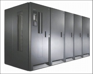
Figure 2-35 TS3500 Tape Library
Proven reliable tape handling and functional enhancements result in a robust enterprise solution with outstanding retrieval performance. Typical cartridge move time is less than three seconds. For optimal results, use TS1120, TS1130, or LTO Ultrium high-density cartridge technology. The TS3500 Tape Library provides a powerful tape storage solution with a minimal footprint.
In summary, the TS3500 Tape Library provides the following advantages:
•A modular, scalable, and automated tape library that combines IBM tape and automation for open systems and mainframe hosts.
•It uses a variety of IBM drive types.
•The TS3500 Tape Library allows attachment to IBM System z, IBM System i®, IBM System p, IBM RS/6000®, and IBM System x. In addition, it can attach to IBM Netfinity®, Oracle, Hewlett-Packard, and other non-IBM servers.
•Connectivity includes using FICON, ESCON, Fibre Channel, Low Voltage Differential (LVD) SCSI, and High Voltage Differential (HVD) SCSI.
•IBM Multi-Path Architecture supports redundant control paths, mixed drive configurations, and library sharing between applications.
|
More information: See the TS3500 documentation for more information about the TS3500 Tape Library features and capabilities.
|
TS3500 Tape Library frame models
The TS3500 Tape Library is available in several models to provide a broad and flexible range of configuration options for the user. Each frame model offers different capabilities and functions. These capabilities include the accessor frame, tape drive type, and storage cells that are supported.
The TS3500 Tape Library’s scalability allows you to increase capacity from a single base frame up to fifteen additional storage units. These additional units are called expansion frames. The storage units that can be attached to a TS7740 Virtualization Engine are described. For a complete list of frame models and a description of their features and capabilities, see the TS3500 Tape Library product documentation.
The following tape library frame models are available:
•TS3500 Tape Library Model L23: A base frame that contains up to 12 IBM 3592 Tape Drives and up to 260 IBM TotalStorage 3592 tape cartridges. Frame L23 also can be equipped with TS7740 back-end fiber switches. Use FC4872 for 4 Gb Fibre Channel switches or two FC4875s for 8 Gb Fibre Channel switches.
•TS3500 Tape Library Model D23: An expansion frame that can house up to 12 IBM 3592 Tape Drives and up to 400 IBM TotalStorage 3592 tape cartridges. Up to 15 expansion frames can be installed with a base frame. Frame D23 can also be equipped with TS7740 back-end fiber switches. Use FC4872 for 4 Gb FC switches or two FC4875s for 8 Gb FC switches. Frame D23 can also be configured as the second service bay in an HA configuration. This can only be done if not equipped with four I/O stations.
•IBM 3584 Model HA1: An optional HA frame usable with service bay features on the TS3500 Tape Library Models D23 and D53. This model supports the installation of a second accessor in the TS3500 Tape Library.
•TS3500 Tape Library Model S24: A driveless storage-only high-density expansion frame for up to 1,000 3592 tape cartridges. Up to 15 expansion frames can be installed with a base frame. Advanced Library Management System (ALMS) is required for any library with a Model S24 frame. This frame can optionally be configured as the second service bay. High density (HD) slots contain the tape cartridges in a tiered architecture. The cartridge immediately accessible in the HD slot is a Tier1 cartridge. Behind this is Tier2, and so on. The maximum number of tiers in an S24 frame is four.
Figure 2-36 on page 101 shows the TS3500 Tape Library High Density frame.

Figure 2-36 TS3500 Tape Library High Density frame
The Lxx frames also contain an I/O station for 16 cartridges. If both LTO and IBM 3592 Tape Drives are installed inside the TS3500 Tape Library, the optional second I/O station is required for the second media format. The second I/O station is installed below the first I/O station. The drive type in the Lxx frame determines which I/O station is in the top position. In an L23 frame (equipped with 3592 tape drives), the I/O station for 3592 cartridges is in the top position.
All currently available frame models can be intermixed in the same TS3500 Tape Library as the previously installed frame models. Previous frame models include the L22, L32, L52, D22, D32, and D52.
|
Tip: See the TS3500 Tape Library documentation for a complete description of the frame models, feature codes, and capabilities.
|
TS3500 Tape Library attached to TS7740 Virtualization Engine
The TS3500 Tape Library houses the physical tape drives for a TS7740 Virtualization Engine. A dedicated logical library is required in the TS3500 Tape Library for each TS7740 Virtualization Engine. The back-end drives are assigned to this partition for exclusive use by the attached TS7740 Virtualization Engine. Defining a Cartridge Assignment Policy (CAP) for the TS7740 Virtualization Engine partition helps you process the physical cartridges to go into the TS3500 Tape Library.
The TS3500 Tape Library also houses the fiber switches belonging to the attached TS7740 Virtualization Engine. To support this configuration, the TS3500 must include a frame model L23 or D23. This frame model must be equipped with the TS7740 back-end switches. Use FC 4872 for 4-Gb FC switches or two FC 4875s for 8-Gb FC switches. Each TS7740 Virtualization Engine must have its own set of fiber switches. You can have more than one TS7740 attached to the same TS3500 Tape Library.
|
Requirement: Advanced Library Management System (ALMS) must be enabled in a TS3500 Tape Library to support the attachment of tape subsystems to System z hosts.
|
The TS7740 Virtualization Engine requires a minimum of four dedicated physical tape drives and supports a maximum of 16 drives. These drives can reside in the TS3500 Tape Library Model L23/L22 Base Frame and Model D23/D22 Drive Frames. Up to twelve drives can be installed in one frame. The TS7740 Virtualization Engine-attached drives do not have to be installed in contiguous positions. For availability and performance reasons, spread the drives evenly across two frames in close proximity to each other.
TS7740 Virtualization Engine-attached drives cannot be shared with other systems. However, they can share a frame with tape drives attached to the following items:
•Other TS7740 Virtualization Engines
•Tape controllers
•Open Systems hosts
The TS7740 Virtualization Engine supports IBM 3592 Model J1A, TS1120, TS1130, and TS1140 tape drives. The IBM 3592-J1A Tape Drive has been withdrawn from marketing, but existing drives can be used for TS7740 Virtualization Engine attachment. When TS1120 drives are intermixed with 3592-J1A drives on the same TS7740 Virtualization Engine, the TS1120 drives must run in J1A emulation mode. When only TS1120 drives are attached to a TS7740 Virtualization Engine, set them to native E05 mode. TS1130 drives cannot be intermixed with either TS1120 drives or J1A tape drives. TS1140 drives cannot be intermixed with any other drive technology.
Logical libraries in the TS3500 Tape Library
The TS3500 Tape Library features the storage area network (SAN)-ready Multi-Path Architecture. This architecture allows homogeneous or heterogeneous Open Systems applications to share the library’s robotics. It does not require middleware or a dedicated server (host) acting as a library manager. The SAN-ready Multi-Path Architecture allows you to partition the library’s storage slots and tape drives into logical libraries. Servers can then run separate applications for each logical library. This partitioning capability extends the potential centralization of storage that the SAN enables.
The TS3500 Tape Library takes Multi-Path Architecture to the next level. It implements the Advanced Library Management System (ALMS). ALMS is an optional feature for the TS3500 Tape Library in general. However, in a System z host-attached library, such as the library that is described here, ALMS is mandatory. ALMS provides improved flexibility with these features in a user-friendly web interface:
•Defining logical libraries
•Allocating resources
•Managing multiple logical libraries
Multiple logical libraries can coexist in the same TS3500 Tape Library that is connected to different resources. These other resources can include the following resources:
•Other TS7740 Virtualization Engines
•Virtual Tape Server (VTS) and Native Tape Controllers (using the IBM 3953 F05 frame)
•Open System hosts
The TS7740 Virtualization Engine must have its own logical library partition within the TS3500 Tape Library.
For details of the TS3500 Tape Library, see IBM TS3500 Tape Library with System z Attachment A Practical Guide to Enterprise Tape Drives and TS3500 Tape Automation, SG24-6789.
2.5.5 IBM TotalStorage 3592-J1A Tape Drive
The IBM TotalStorage 3592-J1A is the first generation of the 3592 family. The 3592 Tape Drive family replaces the prior generation of 3590 Tape Drives. The 3592-J1A provides the following capabilities:
•Up to 40 MBps native data rate, which is over 2.5 times the 14 MBps for the 3590 E or H models
•Up to 300 GB native cartridge capacity (900 GB at 3:1 compression), which is a five-time increase over the 60 GB for the 3590 H models
•A 60 GB Economy tape cartridge with fast read/write access
•300 GB and 60 GB Write Once Read Many (WORM) cartridges for increased security of data
|
Tip: The IBM TotalStorage 3592-J1A has been withdrawn. Its replacements are the TS1120 Tape Drive, TS1130 Tape Drive, and the TS1140 Drive.
The IBM TotalStorage 3592-J1A does not support Media Type JB.
|
2.5.6 IBM System Storage TS1120 Tape Drive
The IBM System Storage TS1120 Tape Drive (3592-E05) is the second generation in the 3592 family. Encryption support was added later in the product life. Existing 3592-E05 drives can be upgraded to encryption-capable if needed by using FC5592. The TS1120 Tape Drive delivers 100 MBps data rate and 700 GB uncompressed capacity. It has the following capabilities:
•The E05 models can read cartridges written by J1A drives and write in J1A emulation mode. The drive can dynamically change its mode of operation per physical cartridge.
•The 3592-E05 Tape Drives can be intermixed with 3592-J1A Tape Drives:
– In the same TS3500 Tape Library frame
– Connected to the same TS7740 Virtualization Engine
When intermixed with 3592-J1A Tape Drives, the TS1120 Model E05 Tape Drive always operates in J1A emulation mode. This is the same behind the same TS7740 Virtualization Engine or other controller. To use the full capacity and functionality of the TS1120 Model E05, do not intermix it with J1A Tape Drives.
2.5.7 IBM System Storage TS1130 Tape Drive
The IBM System Storage TS1130 Tape Drive is the third generation in the IBM 3592 Tape Drive family. The TS1130 Tape Drive provides higher capacity and performance compared to previous generations. It provides a native data rate of up to 160 MBps and uncompressed capacity of 1 TB with the Extended Data Cartridge (JB).
The TS1130 Tape Drive is available in two 3592 models: E06 and EU6. Model EU6 is only available as an upgrade of an existing TS1120 Tape Drive Model E05 to the TS1130 Tape drive. The TS1130 Tape Drive supports the following capabilities:
•Data encryption and key management
•Downward read compatible (n-2) to the 3592 Model J1A
•Downward write compatible (n-1) to the 3592 Model E05 formats
The TS1130 Tape Drive uses the same IBM 3592 Cartridges as the TS1120 and 3592-J1A. Attachments to System z and Open Systems platforms are maintained.
The TS1130 shares the following enhancements with the previous model numbers:
•Redundant power supplies.
•Larger, 1.1 GB (1 GiB) internal buffer on Model E06/EU6, 536.9 MB (512 MiB) for Model E05, 134.2 MB (128 MiB) for Model J1A.
•Dynamic digital speed matching, individual read/write data channel calibration, and increased search speed.
•Streaming Lossless Data Compression (SLDC) algorithm.
•Advanced Encryption Standard (AES) 256-bit data encryption capability increases security with minimal performance impact.
•Up to 160 Mibit/sec. native data rate for the Models E06 and EU6, four times faster than the Model J1A at 40 Mibit/sec. (Up to 100 Mibit/sec. for the Model E05).
•Up to 1073.7 GB (1000 GiBs) native cartridge capacity for the Models E06 and EU6 using the IBM TotalStorage Enterprise Tape Cartridge 3592 Extended (3221.2 GB [3000 GiB] at 3:1 compression), more than a three-fold increase over the maximum 322.1 GB (300 GiB) native tape cartridge capacity (966.3 GB [900 GiB] at 3:1 compression) of Model J1A.
•Up to 687.2 GB (640 GiB) native cartridge capacity for the Models E06 and EU6 using the standard IBM TotalStorage Enterprise Tape Cartridge 3592 (2061.6 GB [1920 GiB] at 3:1 compression), more than a two-fold increase over the maximum 322.1 GB (300 GiB) native tape cartridge capacity (966.4 GB [900 GiB] at 3:1 compression) of Model J1A.
•137.4 GB (128 GiB) for Models E06 and EU6, 107.4 GB (100 GiB) for Model E05, and 64.2 GB (60 GiB) for Model J1A on the Economy tape cartridge with fast read/write access.
•1073.7 GB (1000 GiB), 687.2 GB (640 GB), and 137.4 GB (128 GiB) WORM capacities on Models E06 and EU6 for increased security of data (compared to 751.6 GB (700 GiB), 536.9 GB (500 GiB), and 107.4 GB (100 GiB) WORM capacities for Model E05 and 322.1 GB (300 GiB) and 64.2 GB (60 GiB) for Model J1A).
•Scaling capability to optimize fast access, storage capacity, or a combination of both.
•Dual-ported switched fabric 4-Gibit/sec. Fibre Channel attachments.
•High reliability and availability design.
2.5.8 IBM System Storage TS1140 Tape Drive
The IBM System Storage TS1140 Tape Drive Model E07 (machine type 3592) is the fourth generation of the highly successful IBM 3592 Enterprise Tape Drive. It is supported for integration in the IBM System Storage TS3500 Tape Library.
The TS1140 Tape Drive is designed to provide higher levels of performance, reliability, and cartridge capacity than the TS1130 Model E06 Tape Drive. It has a high-technology 32-channel giant magneto-resistive (GMR) head design and provides a native data rate performance of up to 250 MB/sec versus the 160 MB/sec data rate of the TS1130 Tape Drive Model E06. With the use of the IBM Tape Cartridge 3592 Advanced Data (Type JC), the TS1140 Model E07 can format a cartridge uncompressed up to 4.0 TB (12.0 TB with 3:1 compression). The TS1140 Tape Drive supports the following capabilities:
•With the appropriate drive microcode level installed, it is downward read (n-3) and downward write (N-1)
•Data encryption and key management
The TS1140 offers the following enhancements:
•Up to 250 MB/s native data rate for the Model E07, which is six times faster than the
Model J1A at 40 MB/s.
Model J1A at 40 MB/s.
•Dual-port 8-Gbps Fibre Channel interface.
•Up to 4000 GB (3725.3 GiB) native cartridge capacity for Model E07 on the IBM Tape Cartridge 3592 Advanced Data, more than a ten-fold increase over the maximum 300 GB (279.39 GiB) native cartridge capacity of Model J1A on the 3592 Standard Data cartridge.
•Up to 1600 GB (1490.12 GiB) native cartridge capacity for the Model E07 and 1000 GB (931.32 GiB) for Models E06 and EU6 using the IBM Tape Cartridge 3592 Extended Data. Using the E07 tape drive at 3:1 compression, the maximum capacity is 4800 GB
(4470.35 GiB), more than a five-fold increase over the maximum 300 GB (279.39 GiB) native tape cartridge capacity (900 GB [838.19 GiB] at 3:1 compression) of Model J1A using the Standard Data cartridge.
(4470.35 GiB), more than a five-fold increase over the maximum 300 GB (279.39 GiB) native tape cartridge capacity (900 GB [838.19 GiB] at 3:1 compression) of Model J1A using the Standard Data cartridge.
•Up to 500 GB (465.66 GiB) for Model E07 on the Advanced Economy cartridge with very fast read and write access.
•Up to 4000 GB (3725.3 GiB) cartridge capacity for Model E07 on the Advanced WORM cartridge for increased security of data. This is more than a three-fold increase over the maximum WORM capacities for Models E06 and EU6 on the Extended WORM cartridge, 1000 GB (931.32 GiB) on the Model E06, and 700 GB (651.93 GiB) on the Model E05.
|
Note: The 3592-E07 supports reading JA, JJ, JR, and JW cartridges only with code level D3I3_5CD or later.
|
TS7700 Virtualization Engine management interface
The TS7700 Virtualization Engine management interface (MI) is a Storage Management Initiative - Specification (SMI-S) compliant interface that provides you a single access point to remotely manage resources through a standard web browser. The TS7700 Virtualization Engine MI is based on a web server that is installed in each TS7700 Virtualization Engine. It must be connected to your LAN using the supplied Ethernet connection to have the management interface fully accessible to the user and operational.
The MI is required for implementation and operational purposes:
•Monitor and configure the system.
•Manage access.
•Manage logical and physical volumes.
|
Note: If LDAP policy is enabled, you need a valid LDAP account to use the management interface.
|
New in TS7700 Virtualization Engine Release 3.0 is a graphical user interface with the “look and feel” of the V7000 and IBM XIV® for unification across storage. Figure 2-37 on page 106 shows the TS7700 Management Interface Navigation Panel.
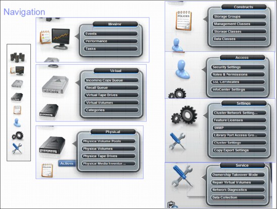
Figure 2-37 TS7700 Management Interface Navigation panel
For more information, see Chapter 5, “Hardware implementation” on page 189 and Chapter 9, “Operation” on page 413.
You can also directly access the TS3500 Tape Library Specialist from the TS7700 MI. Select a TS7740 in the grid, click the small picture of the TS3500, and double-click the large picture of the TS3500. For more details about the IBM System Storage TS3500 Tape Library Specialist, see 9.1.1, “TS3500 Tape Library Specialist” on page 415.
User roles
Users of the TS7700 Virtualization Engine can be assigned one or more roles. User roles are levels of access, assigned by the administrator, that allow users to perform certain functions. User roles are created by using the TS7700 Virtualization Engine management interface. When an administrator creates a new user account, the administrator must specify an initial password for the account. Multiple roles cannot be assigned to a single user.
Administrators can assign the following roles when defining new users:
Operator The operator has access to monitoring information, but is restricted from the following activities:
•Changing settings for performance
•Network configuration
•Feature licenses
•User accounts
•Custom roles
•Inserting and deleting logical volumes
Lead operator The lead operator has almost all of the same permissions as the administrator. However, the lead operator cannot change network configuration, feature licenses, user accounts, and custom roles.
Administrator The administrator has the highest level of authority, including the authority to add or remove user accounts. The administrator has access to all service functions and TS7700 Virtualization Engine resources.
Manager The manager has access to health and monitoring information, jobs and processes information, and performance data and functions. However, the manager is restricted from changing most settings, including settings for logical volume management, network configuration, and feature licenses.
Custom roles The administrator can name and define two custom roles by selecting the individual tasks permitted for each custom role. All available tasks are selectable for a custom role except creating, modifying, and deleting a user. Figure 9-93 on page 549 shows the Roles & Permissions window, including the custom roles.
For more information, see Chapter 9, “Operation” on page 413.
..................Content has been hidden....................
You can't read the all page of ebook, please click here login for view all page.