

Preinstallation planning and sizing
This chapter provides information to help you plan the installation and implementation of the IBM Virtualization Engine TS7700. It covers the following topics:
•Hardware configurations
•Hardware installation and infrastructure planning
•Remote installations and switch support
•High availability (HA) grid considerations
•Tape library attachment
•Planning for software implementation
•Planning for logical and physical volumes
•Planning for encryption in the TS7740 Virtualization Engine
•Tape analysis and sizing the TS7740 Virtualization Engine
•Education and training
•Planning considerations
Use the preinstallation checklists in Appendix C, “TS3500 and TS7700 checklists” on page 867 to help plan your installation.
|
Remember: For this chapter, the term “tape library” refers to the IBM System Storage TS3500 Tape Library.
|
4.1 Hardware configurations
The minimum configurations and the optional enhancements for the TS7700 Virtualization Engine are described. Both the IBM TS7740 Virtualization Engine and the IBM TS7720 Virtualization Engine are covered.
Tape library attachment
The current TS7740 Virtualization Engine no longer implements a physical Library Manager for its TS3500 attached tape library. All Enterprise Library Controller (ELC) functions and associated components are integrated into the TS7700 Virtualization Engine. The TS7720 Virtualization Engine is a disk-only solution and therefore requires no physical tape library.
For more information about the TS3500 Tape Library, see 2.5.4, “TS3500 Tape Library” on page 99.
|
Tip: The IBM 3494 Tape Library attachment is no longer supported from Release 2.0 forward.
|
TS7700 Virtualization Engine configuration summary
Release 3.0 hardware components and configuration requirements for a stand-alone cluster grid and for a multicluster grid configuration are described.
TS7740 (tape-attached) Virtualization Engine configuration summary
A TS7740 Virtualization Engine consists of the following components:
•Frame (3952-F05).
•TS7740 Virtualization Engine Server:
– An IBM System p server (3957 Model V07) with one 3.0 GHz eight-core processor card, 16 GB of 1066 MHz dynamic device reconfiguration 3 (DDR3) memory, and eight small form factor (SFF) hard disk drives (HDDs) with a redundant serial-attached SCSI (SAS) adapter.
– Two I/O expansion drawers.
•Disk cache.
|
The TS7740 has featured different cache models and sizes since it was first launched. In this summary, we list Model CC9/CX9, which is introduced with TS7740 Release 3.0.
|
•One 3956 Model CC9 with up to two 3956 Model CX9s (total of three drawers) providing up to 28.62 TB of data capacity. Considering a compression rate of 3:1, this represents 83.83 TB of uncompressed data.
•Two redundant network switches.
•Two redundant 8 Gb Fibre Channel (FC) switches located in the TS3500 Tape Library that provide connectivity to the 3592 Model J1A, TS1120 Model E05, TS1130 Model E06/EU6, or TS1140 Model E07 tape drives.
•TS3000 System Console (TSSC), LAN hub, and keyboard/display: Can be considered optional if you already have an external TSSC.
TS7720 (disk only) Virtualization Engine configuration summary
A TS7720 Virtualization Engine consists of the following components:
•Frame (3952-F05).
•TS7720 Virtualization Engine Disk Only Server.
An IBM System p server as the node (3957 Model VEB) with one 3.0 GHz eight-core processor card, 16 GB of 1066 MHz DDR3 memory, and 8 SFF HDDs with an external SAS card.
•Two I/O expansion drawers.
•Two redundant network switches.
•TSSC, LAN hub, and keyboard/display: Can be considered optional if you already have an external TSSC.
•Disk cache.
|
The TS7720 has featured different cache models and sizes since it was first launched. In this summary, we list Model CS9/XS9, which is introduced with TS7720 Release 3.0.
|
• One 3956 Model CS9 with up to nine 3956 Model XS9s (total of ten drawers) for a maximum cache size of 239.86 TB of data capacity. Considering a compression rate of 3:1, this represents 719.58 TB of uncompressed data.
•Optional Storage Expansion Frame (3952-F05): One 3956 Model CS9s with up to fifteen drawers of 3956 Model XS9s for a maximum cache size of 623.86 TB. Considering a compression rate of 3:1, this represents 1872 TB of uncompressed data.
|
TS7720 Release 2.1 introduced a second expansion frame via a request for price quotation (RPQ) 8B3604, which increases the maximum native capacity to 580 TB (pre-CS9/XS9 models). 3957-VEB is required for the second expansion frame.
|
In summary, all components are installed in an IBM 3952-F05 Tape Frame. The Virtualization Engine is connected to the host through Fibre Channel connection (FICON) channels, with the tape library and disk cache connected via Fibre Channel adapters.
In a multicluster grid configuration, where you can have up to six TS7700 Virtualization Engines, two or four independent 1 Gb copper or optical grid Ethernet links (single- ported or dual-ported), or alternatively two 10 Gb longwave (LW) optical grid Ethernet links per TS7700 Virtualization Engine, are used to interconnect the clusters.
A copper-based Ethernet network is the communications mechanism between the network switches, client network, TSSC, and virtualization engine.
4.1.1 TS7740 Virtualization Engine configuration details
The specific feature codes (FCs) of the TS7740 Virtualization Engine in a stand-alone and grid configuration are described.
TS7740 Virtualization Engine minimum configuration with R3.0
The minimum configuration of a TS7740 Virtualization Engine build with R3.0 machine code requires the following components. The feature code (FC) number is in parenthesis.
•One 3952 Tape Frame Model F05 with the following required features:
– TS7740 Encryption Capable Base Frame (FC7330)
– Install 3957 V07 (FC5629)
– Plant Install 3956 CC9 (FC5652)
– Integrated Control Path (FC5758)
– Dual AC Power (FC1903)
– Two Ethernet switches
– Optionally, one TSSC
– Ship with R3.0 Machine Code (FC9113)
– A power cord appropriate for the country of installation must be selected from features FC9954 through FC9959, or FC9966.
•One TS7740 Virtualization Engine Server (3957 Model V07) with the following required features:
– One of 1 TB Cache Enablement (FC5267)
– One of 100 MBps Increment (FC5268)
– Dual Port FC host bus adapter (HBA) (FC5240)
– Mainframe Attach (FC9000)
– Ship with R3.0 Machine Code (FC9113)
– Attach to TS3500 (FC9219)
– Plant Install in F05 (FC9350)
– Two of either 10 Gb Grid Optical LW Connection (FC1035), 1 Gb Grid Dual Port Copper Connection (FC1036), or 1 Gb Grid Dual Optical shortwave (SW) Connection (FC1037)
– Either two of host to Virtualization Engine FICON cables (FC0201 or FC0203) or one No Factory Cables (FC9700)
– Two of either FICON Shortwave Attachment (FC3441) or FICON Longwave Attachment (FC3442), or FICON 10 km (6.2 miles) Longwave Attachment (FC3443)
– Console Attachment (FC2715)
|
TS7740 Release 3.0 introduces the Encryption-Capable Cache, which utilizes the new 3956 Cache Controller CC9 along with Expansion Drawer CX9. Both come with 600 GB full disk encryption (FDE)-capable SAS drives.
|
•One TS7740 Cache Controller (3956 Model CC9) is required with the following required features:
– Plant Install in 3952-F05 Encryption Capable Controller (FC9352)
– Plant install 3956-CC9 (FC 5652)
– 13.2 TB SAS Storage (FC 7124)
|
Disk cache encryption is supported in an existing TS7740 Virtualization Engine with 3956-CC8 via an RPQ.
|
•Two 8 Gb Fibre Channel switches are required:
– TS7700 back-end SW Mounting Hardware (FC4871)
– Power Distribution Units (FC1950)
– One power cord FC9954 through FC9959 or FC9966
– 8 Gb Fibre Channel switch (FC4875)
– Attached to LM/TS7700/3592-C07 (FC9217)
– Adjacent frame support for TS7700 back-end Fibre Channel switches (FC4874)
•One or more 3584 Model L23 or D23 frames with the following components:
– From four to sixteen 3592 tape drives: The TS7740 can be attached to 3592 Model J1A, TS1120 Model E05, TS1130 Model E06/EU6 tape drives, or TS1140 Model E07 Tape Drives. All attached drives must operate in the same mode. Intermixing is only supported for TS1120 Model E05 working in 3592-J1A emulation mode and 3592-J1A tape drives. The TS1140 Model E07 Tape drive cannot be intermixed with another drive type.
|
Tip: JA and JJ media are only supported for read-only operations by TS1140 Model E07 Tape Drives. Existing JA or JJ media will be marked read-only and moved to a sunset category after reclamation, which allows them to be later ejected by the user.
|
– Up to 16 FC1515, 3592 Fibre Channel Tape Drive mounting kit.
TS7740 Virtualization Engine configuration upgrades
See Chapter 7, “Upgrade considerations” on page 329 for available upgrades.
4.1.2 TS7720 Virtualization Engine configuration details
The specific features of the TS7720 Virtualization Engine in the stand-alone and grid configurations are described.
TS7720 Virtualization Engine minimum configuration with R3.0
The minimum configuration of a TS7720 Virtualization Engine build with R3.0 machine code requires the components that are described here:
•One 3952 Tape Frame Model F05 with the following required features:
– TS7720 Virtualization Engine Encryption-Capable Base Frame (FC7331)
– Plant Install 3957 VEB (FC5627)
– Plant Install 3956 CS9 (FC5651)
– Integrated Control Path (FC5758)
– Dual AC Power (FC1903)
– Two Ethernet switches
– Optionally, one TSSC
– Ship with R3.0 Machine Code (FC9113)
– A power cord appropriate for the country of installation must be selected from FC9954 through FC9959, or FC9966.
•One TS7720 Virtualization Engine Server (3957 Model VEB) with the following required features:
– 100 MBps Throughput - Plant (FC9268)
– Mainframe Attach (FC9000)
– Ship with R3.0 Machine Code (FC9113)
– Plant Install in 3952-F05 (FC9350)
– Two of either 10 Gb Grid Optical LW Connection (FC1035), 1 Gb Grid Dual Port Copper Connection (FC1036), or 1 Gb Grid Dual Optical SW Connection (FC1037)
– Either two of host to Virtualization Engine FICON cables (FC0201 or FC0203) or one No Factory Cables (FC9700)
– Two of either FICON Shortwave Attachment (FC3441), FICON Longwave Attachment (FC3442), or FICON 10 km (6.2 miles) Longwave Attachment (FC3443)
– Console Attachment (FC2715)
•One TS7720 Cache Controller (3956 Model CS9) with the following required features:
– 36 TB SAS Storage (FC7115)
– Plant install 3956-CS9 (FC5651)
– Plant install in 3952-F05 (FC9352) Encryption Capable Controller
TS7720 Virtualization Engine configuration upgrades
For available upgrades, see Chapter 7, “Upgrade considerations” on page 329.
TS7720 Storage Expansion frame
To attach a TS7720 Storage Expansion frame to a TS7720 base frame, configure the following components:
•One 3952 Tape Frame Model F05 with the following required features:
– TS7720 Encryption-capable Expansion Frame (FC7332)
– One Plant Install 3956-CS9 (FC5651)
– Cache Controller Disk Encryption Enable (FC5272) for cache controller
– Cache Expansion Drawer Disk Encryption Enable (FC7404) for expansion drawer
– Plant install TS7700 Cache in a 3952-F05 (FC9352)
– Zero - 15 of Plant Install 3956-XS9 (FC5655)
– Zero - 15 of Field Install 3956-XS7 (FC5656)
|
Tip: Valid quantities of FC5655 plus FC5656 are zero - 15.
|
– Dual AC Power (FC1903)
– A power cord appropriate for the country of installation must be selected from FC9954 through FC9959, or FC9966
•On an existing TS7720 Non-Encryption-Capable Virtualization Engine base frame (3952 Tape Frame Model F05 with FC7322), the following features are required, in addition to the minimum configuration and optional requirements defined above:
– Expansion Frame Attach (FC9323)
– Existing TS7720 base can have 0 to six instances of combined FC5646 and FC5647.
•An existing TS7720 Virtualization Engine Server (3957 Model VEA) installed in the TS7720 base frame (3952 Tape Frame Model F05 with features FC7322 and FC9323) needs to have the following features in addition to the minimum configuration and optional requirements defined above:
– Dual Port FC HBA (FC5240)
– 8 GB memory upgrade (FC3461 or FC9461)
•On a TS7720 Virtualization Engine Server (3957 Model VEB) base frame (FC7322 and FC9323) or 3957-VEB Encryption-capable base frame (FC7331 and FC9323), the following feature is required in addition to the minimum configuration above:
– Dual Port FC HBA (FC5241)
4.1.3 Cables
The cable feature codes for attachment to the TS7700 Virtualization Engine and additional cables, fabric components, and cabling solutions are described.
Required cable feature codes
The following cable feature codes are needed for attachment to the TS7700 Virtualization Engine.
A TS7700 Virtualization Engine Server with the FICON Attachment features (FC3441, FC3442, or FC3443) can attach to FICON channels of IBM System z mainframe, IBM zSeries server, or IBM S/390® server using FICON cable features ordered on the TS7700 Virtualization Engine Server. A maximum of four FICON cables, each 31 meters in length, can be ordered.
One cable must be ordered for each host system attachment by using the following cable features:
•Gbps FICON Long-Wavelength Attachment feature (FC3442 and FC3443): The FICON long wavelength adapter shipped with FC3442 (4-Gbps FICON Long-Wavelength Attachment) or FC3443 (4-Gbps FICON 10 km Long-Wavelength Attachment) has an LC Duplex connector, and can connect to FICON long wavelength channels of IBM zEnterprise®, IBM System z9®, IBM System z10®, or S/390 servers utilizing a 9-micron single-mode fibre cable. The maximum fibre cable length is 4 KM (2.48 miles) for FC3442 and 10 KM (6.2 miles) for FC3443. If standard host attachment cables (31m) are desired, they can be specified with FC0201 - 9 Micron LC/LC 31 meter Fibre Cable.
•Gbps FICON Short-Wavelength Attachment feature (FC3441): The FICON short wave-length adapter shipped with FC3441 has an LC Duplex connector, and can connect to FICON short wavelength channels of zEnterprise, System z9, System z10, or S/390 servers utilizing a 50-micron or 62.5-micron multimode fibre cable. At 4 Gb/sec, the maximum fibre cable length allowed by 50-micron cable is 150 m, or 55 m if using 62.5-micron cable. If standard host attachment cables are desired, they can be specified with FC0203 - 50 Micron LC/LC 31 meter Fibre Cable.
Additional cables, fabric components, and cabling solutions
Conversion cables from SC Duplex to LC Duplex are available as features on the System z servers if you are currently using cables with SC Duplex connectors that now require attachment to fibre components with LC Duplex connections. Additional cable options, along with product support services, such as installation, are offered by IBM Global Services Networking Services. See the IBM Virtualization Engine TS7700 Introduction and Planning Guide, GA32-0568, for Fibre Channel cable planning information. If Grid Enablement (FC4015) is ordered, Ethernet cables are required for the copper/optical 1 Gbps and optical longwave adapters to attach to the communication grid.
4.1.4 Limitations
Consider the following limitations when performing the TS7700 Virtualization Engine preinstallation and planning:
•Each Tape Subsystem component (TS3500 or TS7700 Virtualization Engine node) must be located within 100 feet or a reasonable distance for an IBM service support representative (SSR) to walk to and from during the servicing of a TS7700 or TS3500.
•Intermixing different models of 3592 Tape Drives are not supported in the same TS7740 Virtualization Engine. The only exception is 3592-J1A and TS1120 operating in J1A emulation mode.
•The 3592 back-end tape drives for a TS7740 cluster must be installed in a TS3500 Tape Library. Connections to 3494 Tape Libraries are no longer supported as of R2.0 machine code.
•Clusters running R3.0 machine code can only be joined in a grid with clusters running either R2.0 or R2.1 machine code. No more than two different code levels are allowed within the same grid.
Tape drives and media support (TS7740 Virtualization Engine only)
The TS7740 supports all four generations of the 3592 Tape Drives: 3592 Model J1A, TS1120 Model E05, TS1130 Model E06, and the TS1140 Model E07 tape drives. Support for the fourth generation of the 3592 tape drive family (TS1140 Model E07) was included after General Availability of Release 2.0 of Licensed Internal Code. At this machine code level, the TS1140-E07 tape drive cannot read 3592 Tape Cartridge JA or 3592 Economy Tape Cartridge JJ.
|
Starting with Release 2.1 of Licensed Internal Code, the reading of JA and JJ media by the TS1140-E07 Tape Drive is supported. This capability enables users to upgrade the tape library tape drives to the TS1140 Model E07 while still having active data on JA or JJ media.
|
The TS1140 supports the 3592 Tape Cartridge JA (read-only), 3592 Expanded Capacity Cartridge JB, 3592 Advanced Tape Cartridge JC, 3592 Economy Tape Cartridge JJ (read-only), and 3592 Economy Advanced Tape Cartridge JK.
|
Note: Not all cartridge media types and media formats are supported by all 3592 Tape Drive models. See Table 4-1 for the media, format, and drive model compatibility to see which tape drive model is required for a certain capability.
|
Table 4-1 Supported 3592 read/write formats
|
3592
Tape Drive
|
EFMT1
512 tracks,
eight R/W channels
|
EFMT2
896 tracks,
16 R/W channels
|
EFMT3
1152 tracks,
16 R/W channels
|
EFMT4
2176 tracks,
32 R/W channels
|
|
Model J1A
|
Read/write
|
Not supported
|
Not supported
|
Not supported
|
|
Model E05
|
Read/write1
|
Read/write
|
Not supported
|
Not supported
|
|
Model E06
|
Read
|
Read/write
|
Read/write
|
Not supported
|
|
Model E07
|
Read2
|
Readb
|
Read/write3
|
Read/write
|
1 Model E05 can read and write EFMT1 operating in native or J1A emulation mode.
2 Model E07 can read JA and JJ cartridge types only with tape drive firmware level of D3I3_5CD or higher.
3 Cartridge type JB only.
|
Tip: Remember that no intermix of tape drive models is supported by TS7740, except for the 3592-E05 Tape Drives working in J1A emulation mode and 3592-J1A tape Drives (those were the first and second generation of the 3592 tape drives).
TS1130 (3592 Model E06) cannot be intermixed with any other model of 3592 Tape Drive within the same TS7740.
TS1140 (3592 Model E07) cannot be intermixed with any other model of 3592 Tape Drive within the same TS7740 configuration.
|
Support for the third generation of the 3592 drive family, TS1130 Model E06 and EU6, was included in TS7700 Virtualization Engine Release 1.5. The 3592 Model EU6 Tape Drive was only available as a field upgrade from the TS1120 Tape Drive Model E05, being functionally equivalent to the regular TS1130 3592-E06 Tape Drive. Table 4-2 summarizes the tape drive models, capabilities, and supported media by drive model.
Table 4-2 Summary of the 3592 Tape Drive models and characteristics versus supported media and capacity
|
3592 drive type
|
Supported media type
|
Encryption support
|
Capacity
|
Data rate
|
|
TS1140 Tape Drive
(3592-E07 Tape Drive)
|
JB
JC
JK
Media read only:
JA
JJ
|
Yes (IBM Tivoli Key Lifecycle Manager or
IBM Security Key Lifecycle Manager only)
|
1.6 TB (JB native)
4.0 TB (JC native)
500 GB (JK native)
4.0 TB (maximum all)
|
250 MB/s
|
|
TS1130 Tape Drive
(3592-EU6 or 3592-E06 Tape Drive)
|
JA
JB
JJ
|
Yes
|
640 GB (JA native)
1.0 TB (JB native)
128 GB (JJ native)
1.0 TB (maximum all)
|
160 MB/s
|
|
TS1120 Tape Drive
(3592-E05 Tape Drive)
|
JA
JB
JJ
|
Yes
|
500 GB (JA native)
700 GB (JB native)
100 GB (JJ native)
700 GB (maximum all)
|
100 MB/s
|
|
3592-J1A
|
JA
JJ
|
No
|
300 GB (JA native)
60 GB (JJ native)
300 GB (maximum all)
|
40 MB/s
|
The media type is the format of the data cartridge. The media type of a cartridge is shown by the last two characters on standard bar code labels. The following media types are supported:
•JA - An Enterprise Tape Cartridge (ETC)
A JA cartridge can be used in native mode in a 3592-J1A drive or a 3592-E05 Tape Drive operating in either native mode or J1A emulation mode. The native capacity of a JA tape cartridge used in a 3592-J1A drive or a 3592-E05 Tape Drive in J1A emulation mode is 300 GB (279.39 GiB). The native capacity of a JA tape cartridge used in a 3592-E05 Tape Drive in native mode is 500 GB (465.6 GiB). The native capacity of a JA tape cartridge used in a 3592-E06 drive in native mode is 640 GB (596.04 GiB).
|
Important: The JA media type is only supported for read-only use with TS1140 Tape Drives.
|
•JB - An Enterprise Extended-Length Tape Cartridge (ETCL)
Use of JB tape cartridges is supported only with TS1140 Tape Drives, TS1130 Tape Drives, and TS1120 Tape Drives operating in native capacity mode.
When used with TS1140 Tape Drives, JB media that contains data written in native E05 mode is only supported for read-only operations. After this data is reclaimed or expired, the cartridge can be written from the beginning of the tape in the new E07 format. If previously written in the E06 format, appends are supported with the TS1140 drive.
The native capacity of a JB tape cartridge used in a 3592-E05 drive is 700 GB
(651.93 GiB). When used in a 3592-E06 drive, the JB tape cartridge native capacity is 1000 GB (931.32 GiB). When used within a Copy Export pool, a JB tape cartridge can be written in the E06 format with a TS1140 drive allowing Copy Export restores to occur with TS1130 hardware. The native capacity of a JB media used in a 3592-E07 Tape Drive in native mode is 1600 GB (1490.12 GiB).
(651.93 GiB). When used in a 3592-E06 drive, the JB tape cartridge native capacity is 1000 GB (931.32 GiB). When used within a Copy Export pool, a JB tape cartridge can be written in the E06 format with a TS1140 drive allowing Copy Export restores to occur with TS1130 hardware. The native capacity of a JB media used in a 3592-E07 Tape Drive in native mode is 1600 GB (1490.12 GiB).
•JC - An Enterprise Advanced Data Cartridge (EADC)
This media type is only supported for use with TS1140 Tape Drives. The native capacity of a JC media used in a 3592-E07 drive is 4 TB (3.64TiB).
•JJ - An Enterprise Economy Tape Cartridge (EETC)
A JJ cartridge can be used in native mode in a 3592-J1A drive or a 3592-E05 Tape Drive operating in either native mode or J1A emulation mode. The native capacity of a JJ tape cartridge used in a 3592-J1A drive or 3592-E05 Tape Drive in J1A emulation mode is
60 GB (58.88 GiB). The native capacity of a JJ tape cartridge used in a 3592-E05 Tape Drive in native mode is 100 GB (93.13 GiB). A JJ cartridge can be used in native mode in a 3592-J1A drive or a 3592-E05 Tape Drive operating in either native mode or J1A emulation mode.
60 GB (58.88 GiB). The native capacity of a JJ tape cartridge used in a 3592-E05 Tape Drive in native mode is 100 GB (93.13 GiB). A JJ cartridge can be used in native mode in a 3592-J1A drive or a 3592-E05 Tape Drive operating in either native mode or J1A emulation mode.
|
Important: The JJ media type is only supported for read-only use with TS1140 Tape Drives.
|
•JK - An Enterprise Advanced Economy Tape Cartridge (EAETC)
This media type is only supported for use with TS1140 Tape Drives. The native capacity of a JK media used in a 3592-E07 drive is 500 GB (465.66 GiB).
The following cartridges are diagnostic and cleaning cartridges:
•CE - Customer Engineer (CE) diagnostic cartridge for use only by IBM SSRs. The VOLSER for this cartridge is CE xxxJA, where a space occurs immediately after CE and xxx equals three numerals.
•CLN - Cleaning cartridge. The VOLSER for this cartridge is CLN xxxJA, where a space occurs immediately after CLN and xxx equals three numerals.
|
Important: Write Once Read Many (WORM) cartridges, JW, JR, JX, and JY, are not supported. Capacity scaling of 3592 tape media is also not supported by the Virtualization Engine TS7740.
|
4.1.5 TS3500 Tape Library High Density frame for a TS7740 Virtualization Engine configuration
A TS3500 Tape Library High Density frame is supported by a TS7740 Virtualization Engine and holds the stacked volumes.
If you are planning to size TS7740 Virtualization Engine physical volume cartridges, this high density (HD) frame can be a solution in terms of floor space reduction.
The TS3500 Tape Library offers high-density, storage-only frame models (HD frames) designed to greatly increase storage capacity without increasing frame size or required floor space.
The new HD frame (Model S24 for 3592 tape cartridges) contains high-density storage slots as shown in Figure 4-1.

Figure 4-1 TS3500 Tape Library HD frame (left) and top-down view
HD slots contain tape cartridges in a tiered architecture. The cartridge immediately accessible in the HD slot is a Tier 1 cartridge. Behind that is Tier 2 and so on. The maximum tier in a 3592 (Model S24) HD slot is Tier 4.
The HD frame Model S24 provides storage for up to 1,000 3592 tape cartridges.
The base capacity of Model S24 is 600 cartridges, which are stored in Tiers 0, 1, and 2. To increase capacity to the maximum for each frame, it is necessary to purchase the High Density Capacity on Demand (HD CoD) feature. This feature provides a license key that enables you to use the storage space available in the remaining tiers.
4.1.6 TS7700 Virtualization Engine upgrades and replacements
The TS7700 Virtualization Engine models V07 and VEB were introduced in Release 2 of the Licensed Internal Code. The feature codes that are available for upgrades and replacements of the existing V06 and VEA models are reviewed. The new feature codes for the V07 and VEB models are described.
See Chapter 7, “Upgrade considerations” on page 329 for existing TS7700 Virtualization Engine component upgrades for functions you might want to enable if you do not have the maximum TS7700 Virtualization Engine configuration.
Licensed Internal Code upgrades from levels earlier than Release 3.0 might also require a hardware reconfiguration scenario. If you currently have a TS7700 Virtualization Engine with a microcode release before R3.0, see 7.3, “TS7700 Virtualization Engine upgrade to Release 3.0” on page 352.
TS7700 Virtualization Engine common feature codes
The following feature codes are available for TS7700 Virtualization Engine models V06 and VEA, and for models V07 and VEB:
•FC1034 Enable dual port grid connection
This feature code enables the second port of each dual port 1-Gb grid connection adapter that is provided by one of these feature codes:
– FC1032 or FC1033 (model V06 or VEA)
– FC1036 or FC1037 (model V07 or VEB)
•FC5270 Increased logical volumes
This feature code increases by 200,000 the number of logical volumes supported on a cluster. You can use multiple increments of this feature to increase the maximum number of supported logical volumes from 1,000,000 (default) to 4,000,000. Fifteen instances of FC 5270 Increased logical volumes are required to support a new maximum of 4,000,000 logical volumes in a 3957 model V07 or VEB.
|
Restriction: The 3957 models V06 and VEA are limited up to a maximum of 2,000,000 volumes, allowing for up to five increment instances of FC5270.
In a multicluster grid configuration, the maximum number of supported logical volumes is determined by the cluster having the fewest installed instances of FC5270. To increase the number of supported logical volumes across a grid, the required number of FC5270 must be installed on each single cluster in the grid.
Grids with one or more 3957 model V06/VEA clusters are limited to a maximum of 2,000,000 volumes.
|
•FC5271 Selective device access control
This feature code authorizes the use of a set of Management Class policies that allow only certain logical control units or LIBPORT-IDs within a composite library to have exclusive access to one or more volumes. FC5271 (Selective device access control) must be installed on each cluster in the grid before any selective device access control policies can be defined in that grid. Each instance of this feature enables the definition of eight selective device access groups. The default group provides a single access group, resulting in nine total possible access groups.
•FC5272 Enable disk encryption
This is a new feature that was introduced in Release 3.0 of Licensed Internal Code. This feature code delivers a product license key to enable disk-based encryption.
|
Disk encryption is only supported in 3957 model V07 and VEB with the new encryption-capable base frame (FC7330 for model V07 and FC7331 for model VEB).
|
TS7700 Virtualization Engine non-hardware feature codes
The following non-hardware-related feature codes are available for TS7700 Virtualization Engine models V06 and VEA, and for models V07 and VEB:
•FC4015 Grid enablement
This feature code provides a key to enable the communication function that allows a TS7700 Virtualization Engine to communicate with other TS7700 Virtualization Engines in a grid. Each TS7700 Virtualization Engine must have this feature to be able to participate in a grid configuration.
|
Note: Contact your IBM SSR to properly set up, connect, and configure the grid environment.
|
•FC4016 Remove cluster from grid
This feature code delivers instructions for a one-time process to remove a TS7700 cluster from a TS7700 grid. You must order this feature before you can perform an FC4017 Cluster cleanup on any TS7700 cluster configured to participate in a TS7700 grid. If a TS7700 cluster is removed from a TS7700 grid, cleaned up using FC4017 Cluster cleanup, and then joined to a new TS7700 grid, another instance of FC4016 Remove cluster from grid is required to remove the cluster from the new grid.
•FC4017 Cluster cleanup
This feature code facilitates a one-time cluster cleanup to clean the database, delete logical volumes from the Tape Volume Cache (TVC), and remove configuration data for host connections from a TS7700 cluster. If the cluster is a member of a TS7700 grid, the cluster must first be removed from the grid using FC4016 Remove cluster from grid. If another cleanup is required on this TS7700 cluster, another instance of FC4017 Cluster cleanup is required.
•FC5267 1 TB Cache enablement
This feature code delivers a key to enable a 1 TB increment of disk cache to store logical volumes. Only the number of increments that is less than or equal to the amount of physical capacity installed can be enabled.
|
Restriction: FC5267 is available only with the TS7740 Virtualization Engine.
|
•FC5268 100 MiB/sec increment
This feature code delivers a key to enable an additional 100 MiB per second increment of potential peak data throughput. Enabling a data throughput increment does not guarantee that the overall TS7700 Virtualization Engine performs at that data throughput level. However, the installation of the maximum allowed feature codes results in unrestricted peak data throughput capabilities:
– Model V06 or VEA: Maximum of six instances of FC5268 can be ordered.
– Model VEB: Maximum of nine instances of FC5268 can be ordered, plus one Plant Installed FC9268, for a total of ten 100 MiB/sec instances.
– Model V07: Maximum of ten instances of FC5268 can be ordered for a total of ten 100 MiB/sec instances.
•FC9900 Tape encryption configuration (TS7740 only)
This feature code includes publication updates with information about how to enable and configure the TS7740 Virtualization Engine and TS3500 Tape Library to support encryption. This feature also provides an Encryption Key Server publication. You must enable and configure the TS7740 Virtualization Engine to support encryption with the TS1120, TS1130, or TS1140 encryption-capable tape drives.
|
Restrictions: This feature is available only with the TS7740 Virtualization Engine.
FC9900 Tape Encryption configuration is only supported with encryption-capable TS1120, TS1130, or TS1140 tape drives. FC9900 Encryption configuration is not supported by 3592-J1A tape drives.
|
TS7700 Virtualization Engine hardware feature codes
The following hardware-related feature codes are available for TS7700 Virtualization Engine models V06 and VEA, and for models V07 and VEB:
•FC3441 FICON short-wavelength attachment
This feature code provides one short-wavelength 4-Gbps FICON adapter with an LC duplex connector for attachment to a FICON host system short-wavelength channel using a 50-micron or 62.5-micron multi-mode fibre cable. At 4 Gbps, the maximum fibre cable length allowed by 50-micron cable is 150 m (492 ft.), or 55 m (180 ft.) if using 62.5-micron cable. Each 4-Gbps FICON attachment can support up to 256 logical channels.
•FC3442 FICON long-wavelength attachment
This feature code provides one long-wavelength 4-Gbps FICON adapter with an LC duplex connector for attachment of a TS7700 Virtualization Engine to a FICON host system long-wavelength channel using a 9-micron single-mode fibre cable. The maximum fibre cable length is 4 km (2.48 mi.). Each 4-Gbps FICON attachment can support up to 256 logical channels.
•FC3443 FICON 10-km long-wavelength attachment
This feature code provides one long-wavelength 4-Gbps FICON adapter with an LC duplex connector for attachment to a FICON host system long-wavelength channel using a 9-micron single-mode fibre cable. The maximum fibre cable length is 10 km (6.21 mi.). Each 4-Gbps FICON attachment can support up to 256 logical channels.
•FC3461 8 GB Memory upgrade in field
This feature code delivers a field-installed TS7700 server memory upgrade to 16 GB of Random Access Memory (RAM).
|
Tip: FC3461 is only supported on the 3957 V06 or VEA, and requires Licensed Internal Code Release 2.0 or higher.
|
TS7700 Virtualization Engine models V07 and VEB only feature codes
Starting with Release 2.0, the following feature codes are available for TS7700 Virtualization Engine models V07 and VEB only:
•FC1035, 10 Gb grid optical LW connection
This feature code provides a single port, 10-Gbps Ethernet longwave adapter for grid communication between TS7700 Virtualization Engines. This adapter has an SC Duplex connector for attaching 9-micron, single-mode fibre cable. This is a standard longwave (1,310 nm) adapter that conforms to the IEEE 802.3ae standards. It supports distances up to 10 km (6.2 miles).
|
Note: These adapters cannot negotiate down to run at 1 Gb. They must be connected to a 10-Gb network device or light point.
|
•FC1036 1-Gb grid dual port copper connection
This feature code provides a dual port 1-Gbps 10/100/1000 Base-TX PCIe Ethernet adapter for grid communication between TS7700 Virtualization Engines with a single port enabled. This adapter has an RJ-45 connector for attaching Cat6 cables. It conforms to the IEEE 802.3ab 1000 Base-T standard. It supports distances of up to 100 meters using four pairs of Cat6 balanced copper cabling.
•FC1037 1-Gb dual port optical SW connection
This feature code provides a dual port 1-Gbps shortwave PCIe Ethernet adapter for grid communication between TS7700 Virtualization Engines with a single port enabled. This adapter has an LC Duplex connector for attaching 50-micron or 62.5-micron multimode fibre cable. It is a standard shortwave (850 nm) adapter conforming to the IEEE 802.3z standards. It supports distances of up to 260 meters when used with a 62.5-micron cable, and up to 550 meters when used with a 50.0-micron cable.
•FC5241 Dual port FC HBA
This feature code installs two Fibre Channel interface cards in the TS7700 server (3957-V07 or 3957-VEB) and provides two 31-meter, 50µ Fibre Channel cables to connect the TS7700 server to the Fibre Channel switch. When ordered against the TS7740 Server (3957-V07), this feature connects a fibre switch and the back-end tape drives to the 3957-V07. When ordered against the TS7720 Server (3957-VEB), this feature connects the disk arrays in the 3952 Storage Expansion Frame with the 3957-VEB. When Fibre Channel cables connect the TS7700 Virtualization Engine to the Fibre Channel switches, and an 8 Gbps rate is expected, the following maximum length restrictions apply:
– 50µ, 2000 MHz multimode Fibre Channel aqua blue cables cannot exceed 150 meters.
– 50µ, 500 MHz multimode Fibre Channel orange cables cannot exceed 50 meters.
– 62.5µ, 200 MHz Fibre Channel cables cannot exceed 21 meters.
TS7700 Virtualization Engine 3952-F05 Frame feature codes
Starting with Release 2.0 the following feature codes are available for the 3952-F05 Frame of the TS7700 Virtualization Engine:
•FC4743 Remove 3957-V06/VEA
This feature code directs the removal of the 3957-V06 or 3957-VEA from the 3952-F05 Tape Frame. A new 3957-V07 (FC5629 Install 3957-V07) must be ordered to replace a removed 3957-V06. A new 3957-VEB (FC 5627 Install 3957-VEB) must be ordered to replace a removed 3957-VEA. The instructions for the field installation of a new model 3957-V07 or 3957-VEB are delivered with this feature.
|
Restriction: On a Model V06, FC4743 is mutually exclusive with FC5638 (Plant install 3956-CC6). This feature is not supported for the TS7700 F05 Frame with a 3956-CC6 tape cache.
|
•FC5627 Install 3957-VEB
This feature code allows the installation of a TS7720 Server in a 3952-F05 Tape Frame. This feature occurs on the 3952-F05 Tape Frame order:
– For a plant install of a 3957-VEB Server in the 3952-F05 Frame, you must also order FC9350 when you order this feature.
– For a field merge of the 3957-VEB Server in the 3952-F05 Frame, you must also order FC9351 when you order this feature. FC4743 Remove 3957-V06/VEA must also be ordered.
•FC5629 Install 3957-V07
This feature code allows the installation of a TS7740 Server in a 3952-F05 Tape Frame. This feature occurs on the 3952-F05 Tape Frame order:
– For a plant install of the 3957-V07 Server in the 3952-F05 Frame, you must also order FC9350 when you order this feature.
– For a field merge of the 3957-V07 Server in the 3952-F05 Frame, you must also order FC9351 when you order this feature. FC4743 Remove 3957-V06/VEA must also be ordered.
|
Restriction: A 3957-V07 Server cannot be field-merged in a 3952-F05 Frame as a replacement for a 3957-V06 Server with 3956-CC6 cache installed.
|
More details about the FC4743 Remove 3957-V06/VEA, FC5627 Install 3957-VEB, and FC5629 Install 3957-V07 options are provided in Chapter 8, “Migration” on page 371.
There are also frame replacement procedures available to replace the entire 3952-F05 Frame that contains a 3956-V06 with a new frame that contains the new 3957-V07, and replacing the entire 3956-VEA Frame with the 3957-VEB Frame. For details about those migration options, see Chapter 8, “Migration” on page 371.
Expanded memory (3957 V06/VEA at R1.7 or a lower level of code)
Existing TS7700 V06 or VEA systems can continue at 8 GB of physical memory. However, an upgrade from 8 GB to 16 GB of physical memory is offered for existing systems. Feature code FC3461 (Memory Upgrade) provides the field upgrade of a 3957-V06 or 3957-VEA Server. This update is targeted for systems that meet one of the following conditions:
•More than 500,000 logical volumes defined and experience heavy host I/O throughput. TS7700 R2.1 or later code will be performance-tuned to take advantage of the additional memory.
•Existing 3957-V06 or 3957-VEA Servers (stand-alone or grid) that are planned to be upgraded to Release 2.1 or higher.
•Existing 3957-V06 or 3957-VEA Servers that are configured in a five-cluster or six-cluster grid.
|
Tip: 16 GB of memory is required for R2.0 or a later level of code.
|
4.2 Hardware installation and infrastructure planning
Planning information related to your TS7700 Virtualization Engine is described. The topics that are covered include system requirements and infrastructure requirements. Figure 4-2 on page 139 shows you an example of the connections and infrastructure resources that might be used for a TS7700 grid with two separate data centers.

Figure 4-2 TS7700 grid configuration example
The legends on Figure 4-2 are described. Refer to the letter on Figure 4-2:
•A: TS7740 3584-L23 library control frame
•B: TS7740 3584-D23 Frames with 3592-J1A, TS1120 (3592-E05), TS1130 (3592-E06), or TS1140 (3592-E07) drives
•C: TS7740 3584-HA frame and 3584-D23/HA frame (optional)
•D: TS7740 3592 data cartridges for the data repository
•E: Fibre connections between TS7740 and the Fibre Switches mounted within 3584-D23 Frame
•F: TSSC for IBM SSRs and Autonomic Ownership Takeover Manager (AOTM)
•G: TS7700 Virtualization Engine
•H: Four Gbit Ethernet (copper or SW fibre) or two 10 Gbit Ethernet for grid communication
•I: Ethernet connections for management interfaces
•J: FICON connections for host workload
•K: FICON fabric infrastructure with extension technology when appropriate
4.2.1 System requirements
Ensure that your facility meets the system requirements for the TS7700 Virtualization Engine when planning for installation. System requirements for installation include requirements for power, cooling, floor leveling, loading, distribution, clearance, environmental conditions, and acoustics.
For a detailed listing of system requirements, see the IBM Virtualization Engine TS7700 Series Introduction and Planning Guide, GA32-0567-14.
IBM 3952 Tape Frame specifications
The 3952 Tape Frame houses the components of the TS7700 Virtualization Engine. Table 4-3 lists the dimensions of the frame enclosing the TS7700 Virtualization Engine.
Table 4-3 Physical characteristics of a maximally configured 3952 Tape Frame
|
Characteristic
|
Value
|
|
Height
|
1804 mm (71.0 in.)
|
|
Width
|
644 mm (25.4 in.)
|
|
Depth
|
1098 mm (43.23 in.)
|
|
Weight
|
270 kg (595.25 lbs.) empty
669.1 kg (1475 lbs.) maximally configured1
|
|
Power
|
240 Vac, 20 amp (single phase)
|
|
Unit height
|
36 U
|
1 See the IBM TS7700 Customer Information Center 3.0.0 under Planning → System requirements. For more detailed information, see TS7720/TS7740 Virtualization Engine specifications and requirements.
Environmental operating requirements
Your facility must meet specified temperature and humidity requirements before installing the TS7700 Virtualization Engine. Table 4-4 shows recommended environmental conditions for the TS7700 Virtualization Engine.
Table 4-4 Environmental specifications
|
Condition
|
Air temperature
|
Altitude
|
Relative humidity1
|
Wet bulb temperature
|
|
Operating
(low altitude) |
10°C - 32°C (50°F - 89.6°F)
|
Up to 5000 ft. amsl
|
20% - 80%
|
23°C (73°F)
|
|
Operating
(high altitude) |
10°C - 28°C (50°F - 82.4°F)
|
5001 ft. amsl - 7000 ft. amsl
|
20% - 80%
|
23°C (73°F)
|
|
Recommended operating range2
|
20°C - 25°C (68°F - 77°F)
|
Up to 7000 ft. amsl
|
40% - 55%
|
N/A
|
|
Power off
|
10°C - 43°C (50°F - 109°F)
|
N/A
|
8% - 80%
|
27°C (80°F)
|
|
Storage
|
1°C - 60°C (33.8°F - 140°F)
|
N/A
|
5% - 80%
|
29°C (84°F)
|
|
Shipping
|
-40°C - 60°C (-40°F - 140°F)
|
N/A
|
5% - 100%
|
29°C (84°F)
|
1 Non-condensing
2 Although the TS7700 Virtualization Engine will operate outside this range, it is strongly advised that you adhere to the recommended operating range.
For a complete list of system requirements, see TS7700 Customer Information Center 3.0.0, under Planning → System Requirements → Environmental requirements.
Power considerations
Your facility must have an available power supply to meet the input voltage requirements for the TS7700 Virtualization Engine.
The 3952 Tape Frame houses the components of the TS7700 Virtualization Engine. The standard 3952 Tape Frame ships with one internal power distribution unit. However, FC1903, Dual AC power, is required to provide two power distribution units to support the high availability characteristics of the TS7700 Virtualization Engine. The 3952 Tape Expansion Frame has two power distribution units and requires two power feeds.
TS7720 Virtualization Engine power requirements
Your facility must have an available power supply to meet the input voltage requirements for the TS7720 Virtualization Engine. Table 4-5 displays the maximum input power for a fully configured TS7720 Virtualization Engine.
Table 4-5 TS7720 Virtualization Engine maximum input power requirements
|
Power requirement
|
Value
|
|
Voltage
|
200 - 240 V AC (single phase)
|
|
Frequency
|
50 - 60 Hz (+/- 3 Hz)
|
|
Current
|
20 A
|
|
Inrush current
|
250 A
|
|
Power (W)
|
4,000 W
|
|
Input power required
|
4.0 kVA (single phase)
|
|
Thermal units
|
13.7 KBtu/hr
|
TS7740 Virtualization Engine power requirements
Your facility must ensure an available power supply to meet the input voltage requirements for the TS7740 Virtualization Engine. Table 4-6 displays the maximum input power for a fully configured TS7740 Virtualization Engine.
Table 4-6 TS7740 Virtualization Engine maximum input power requirements
|
Power requirement
|
Value
|
|
Voltage
|
200 - 240 V AC (single phase)
|
|
Frequency
|
50 - 60 Hz (+/- 3 Hz)
|
|
Current
|
20 A
|
|
Inrush current
|
250 A
|
|
Power (W)
|
4,000 W
|
|
Input power required
|
4.0 kVA (single phase)
|
|
Thermal units
|
13.7 kBtu/hr
|
4.2.2 TCP/IP configuration considerations
The configuration considerations and LAN/WAN requirements for the TS7700 Virtualization Engine are described. Single and multicluster grid configurations are covered. Figure 4-3 on page 142 shows you the different networks and connections used by the TS7700 Virtualization Engine and associated components. We pictured a two-cluster TS7740 grid to show the TS3500 Tape Library Connections (not present in a TS7720 configuration).

Figure 4-3 TCP/IP connections and networks
TS7700 grid interconnect LAN/WAN requirements
The LAN/WAN requirements for the TS7700 Virtualization Engine cross-site grid TCP/IP network infrastructure are described.
The TS7700 grid TCP/IP network infrastructure must be in place before the grid is activated so that the clusters can communicate with one another as soon as they are online. Two or four 1-Gb Ethernet, or two 10-Gb Ethernet connections must be in place before grid installation and activation, including the following equipment:
•Internal Ethernet routers
Ethernet routers are used to connect the network to management interface services operating on existing 3957-VEA or 3957-V06. These routers are still present if the TS7700 Virtualization Engine Server is field-upgraded to a 3957-VEB model or 3957-V07 model, but they are configured as switches by upgrade procedures.
•Internal Ethernet switches
Ethernet switches are used primarily for private communication between components within a cluster in the manufactured 3957-V07 model or VEB model (not upgraded in field).
•External asynchronous transfer mode (ATM) switches or Ethernet extenders
An Ethernet extender or other extending equipment can be used to complete extended distance Ethernet connections. Extended grid Ethernet connections can be any of the following connections:
– 1 Gb copper 10/100/1000 Base-TX
This adapter conforms to the IEEE 802.3ab 1000Base-T standard, which defines gigabit Ethernet operation over distances up to 100 meters using four pairs of CAT6 copper cabling.
– 1 Gb optical shortwave
This SX adapter has an LC Duplex connector that attaches to 50-micron or 62.5-micron multimode fibre cable. It is a standard SW (850 nm) adapter that conforms to the IEEE 802.3z standards. This adapter supports distances of 2 - 260 meters for 62.5-micron Multimode Fiber (MMF) and 2 - 550 meters for 50.0-micron MMF.
– Optical longwave
This adapter supports a maximum of 10 km (6.2 miles) of 1310 nm, 9-micron, single-mode fiber optic cable. It conforms to the IEEE 802.3ae standard. This adapter requires 9-micron single-mode fiber optic cables and uses an SC connector to connect to network infrastructure components.
The default configuration for a TS7700 server from manufacturing (3957-VEB or 3957-V07) is two dual-ported PCIe 1-Gb Ethernet adapters. You can use FC 1035, 10 Gb grid optical LW connection, to add support for two 10-Gb optical longwave Ethernet adapters. If the TS7700 server is a 3957-V07 or 3957-VEB, two instances of either FC 1036 (1 Gb grid dual port copper connection) or FC 1037 (1 Gb dual port optical SW connection) must be installed. This feature improves data copy replication while providing minimum bandwidth redundancy. Clusters configured using two 10-Gb, four 1-Gb, or two 1-Gb clusters can be interconnected within the same TS7700 grid, although the explicit same port-to-port communications still apply.
|
Important: Identify, order, and install any new equipment to fulfill grid installation and activation requirements. The connectivity and performance of the Ethernet connections must be tested prior to grid activation. You must ensure that the installation and testing of this network infrastructure is complete before grid activation.
|
The network between the TS7700 Virtualization Engines must have sufficient bandwidth to account for the total replication traffic. If you are sharing network switches among multiple TS7700 Virtualization Engine paths or with other devices, the sum total of bandwidth on that network must be sufficient to account for all of the network traffic.
The TS7700 Virtualization Engine uses TCP/IP for moving data between each cluster. Bandwidth is a key factor that affects throughput for the TS7700 Virtualization Engine. The following key factors also can affect throughput:
•Latency between the TS7700 Virtualization Engines
•Network efficiency (packet loss, packet sequencing, and bit error rates)
•Network switch capabilities
•Flow control to pace the data from the TS7700 Virtualization Engines
•Inter-switch link capabilities (flow control, buffering, and performance)
The TS7700 Virtualization Engines attempt to drive the network links at the full 1 Gb rate, which might exceed the network infrastructure capabilities. The TS7700 Virtualization Engine supports the IP flow control frames so that the network paces the level at which the TS7700 Virtualization Engine attempts to drive the network. The best performance is achieved when the TS7700 Virtualization Engine is able to match the capabilities of the underlying network, resulting in fewer dropped packets.
|
Remember: When the system exceeds the network capabilities, packets are lost. This causes TCP to stop, resync, and resend data, resulting in a less efficient use of the network.
|
To maximize network throughput, ensure that the underlying network meets these requirements:
•Has sufficient bandwidth to account for all network traffic expected to be driven through the system to eliminate network contention.
•Can support flow control between the TS7700 Virtualization Engines and the switches. This allows the switch to pace the TS7700 Virtualization Engines to the WAN capability. Flow control between the switches is also a potential factor to ensure that the switches can pace their rates to one another. The performance of the switch is capable of handling the data rates expected from all of the network traffic.
In short, latency between the sites is the primary factor. However, packet loss due to bit error rates or insufficient network capabilities can cause TCP to resend data, therefore multiplying the effect of the latency.
The TS7700 Virtualization Engine uses your LAN/WAN to replicate logical volumes, access logical volumes remotely, and perform cross-site messaging. The LAN/WAN must have adequate bandwidth to deliver the throughput necessary for your data storage requirements. The cross-site grid network is 1 Gb Ethernet with either copper (RJ-45) or shortwave fibre (single-ported or dual-ported) links. For copper networks, Cat 5E or Cat6 Ethernet cabling can be used, but Cat6 cabling is preferable to achieve the highest throughput. Alternatively, two 10 Gb longwave fiber Ethernet links can be provided. For additional information, see “FC1036 1-Gb grid dual port copper connection” on page 137, “FC1037 1-Gb dual port optical SW connection” on page 137, and “FC1035, 10 Gb grid optical LW connection” on page 136. Internet Protocol Security (IPSec) is now supported on grid links to support encryption.
|
Important: To avoid any network conflicts, the following subnets must not be used for LAN/WAN IP addresses or management interface primary, secondary, or virtual IP addresses:
•192.168.251.xxx
•192.168.250.xxx
•172.31.1.xxx
|
Network redundancy
The TS7700 Virtualization Engine provides up to four independent 1 Gb copper (RJ-45) or shortwave fibre Ethernet links for grid network connectivity. We suggest that you connect each link through an independent WAN interconnection to be protected from a single point of failure that can disrupt all WAN operating paths to or from a node.
Local IP addresses for management interface access
|
Beginning with Release 3.0, the 3957-V07 and 3957-VEB configurations will support IPv6 and IPSec.
|
You must provide three TCP/IP addresses on the same subnet. Two of these are assigned to physical links, and the third is a virtual IP address used to connect to the TS7700 Virtualization Engine management interface.
Use the third IP address to access a TS7700 Virtualization Engine. It automatically routes between the two addresses assigned to physical links. The virtual IP address enables access to the TS7700 Virtualization Engine management interface by using redundant paths, without the need to manually specify IP addresses for each of the paths. If one path is unavailable, the virtual IP address automatically connects through the remaining path.
|
Tip: If FC9900, Encryption configuration, is installed, this same connection is used for communications between the TS7740 Virtualization Engine and the Encryption Key Server or Tivoli Key Lifecycle Manager. Because encryption occurs on attached physical tape drives, the TS7720 Virtualization Engine does not support encryption and the virtual connection is used exclusively to create redundant paths.
|
You must provide one gateway IP address.
You must provide one subnet mask address.
|
Important: All three provided IP addresses will be assigned to one TS7700 Virtualization Engine cluster for the management interface access.
|
Each cluster in the grid must be configured in the same manner as explained before, with three TCP/IP addresses providing redundant paths between the local intranet and cluster. Two of these addresses are assigned to physical links, and the third address provides a virtual IP address to connect to the management interface in this specific TS7700 Virtualization Engine.
IPv6 support
Starting with TS7700 Virtualization Engine Licensed Internal Code 3.0, the 3957-V07 and 3957-VEB will support IPv6.
|
Tip: The TS7700 Virtualization Engine grid link interface does not support IPv6.
|
All network interfaces that support monitoring and management functions are now able to support IPv4 or IPv6:
•Management interface
•Key manager server:
– Encryption Key Manager (EKM)
– Tivoli Key Lifecycle Manager
– IBM Security Key Lifecycle Manager
•Simple Network Management Protocol (SNMP) servers
•Lightweight Directory Access Protocol (LDAP) server
•Network Time Protocol (NTP) server
When planning for the NTP server, remember that the NTP server requires IPv6 support in all clusters in the grid.
|
Important: All of these client interfaces must be either IPv6 or IPv4. Mixing IPv4 and IPv6 is not supported currently.
|
For implementation details, see Chapter 5, “Hardware implementation” on page 189.
IPSec support for the grid links
When running TS7700 R3.0 level of Licensed Internal Code, the 3957-V07 and 3957-VEB models support Internet Protocol Security (IPSec) on the grid links. Only use IPSec capabilities if they are absolutely required by the nature of your business. Grid encryption might cause a considerable slowdown in all grid link traffic, for example:
•Synchronous, immediate or deferred copies
•Remote read or write
For implementation details, see Chapter 5, “Hardware implementation” on page 189.
Connecting to the management interface
We describe how to connect to the IBM Virtualization Engine TS7700 Management Interface. Table 4-7 lists the supported browsers.
Table 4-7 Supported browsers
|
Browser
|
Version supported
|
Version tested
|
|
Internet Explorer
|
8.x or 9.x
|
9.x
|
|
Mozilla Firefox
|
6.x, 7.x, 10.x, 10.0.x Extended Support Release (ESR), or 13.x
|
13.x
|
Perform the following steps to connect to the interface:
1. In the address bar of a supported web browser, enter http:// followed by the virtual IP entered during installation, followed by /Console. The virtual IP is one of three IP addresses given during installation. The complete URL takes this form:
http://virtual IP address/Console
2. Press Enter on your keyboard or Go on your web browser.
The web browser redirects to http://virtual IP address/cluster ID, which is associated with the virtual IP address. If you bookmark this link and the cluster ID changes, you must update your bookmark before the bookmark resolves correctly. Alternatively, you can bookmark the more general URL, http://virtual IP address/Console, which does not require an update following a cluster ID change.
3. The login page for the management interface loads. The default login name is admin and the default password is admin.
For the list of required TCP/IP port assignments, see Table 4-8 on page 148.
The management interface in each cluster can access all other clusters in the grid through the Gigabit grid links. From the local cluster menu, by selecting a remote cluster the Maintenance Interface navigates automatically to the selected cluster through the Gigabit grid link. Alternatively, you can point the browser to the IP address of the target cluster that you want.
This function is handled automatically by each cluster’s management interface in the background. Figure 4-4 on page 147 shows a sample setup for a two-cluster grid.

Figure 4-4 TS7700 Virtualization Engine management interface access from a remote cluster
WAN IP addresses for cross-site replication within a multicluster grid
For TS7700 Virtualization Engines configured in a grid, the following additional assignments need to be made for the grid WAN adapters. For each adapter, you must supply the following information:
•A TCP/IP address
•A gateway IP address
•A subnet mask
|
Tip: In a TS7700 Virtualization Engine multicluster grid environment, you need to supply two or four IP addresses per cluster for the physical links required by the TS7700 Virtualization Engine grid for cross-site replication.
|
TSSC Network IP addresses
The TS3000 System Console (TSSC) uses an internal and isolated network, which is known as the TSSC network. All separate elements in the tape subsystem connect to this network and are configured in the TSSC by the IBM SSR.
Each component of your tape subsystem connected to the TSSC uses at least one Ethernet port in the TSSC Ethernet hub. For example, a TS7700 cluster needs two connections (one from the primary switch and other from the alternate switch). If your cluster is a TS7740, you need a third port for the TS3500, the 3584 Tape Library. Depending on the size of your environment, you might need to order a console expansion for your TSSC. See FC2704 in Appendix A, “Feature codes” on page 843 for details.
We suggest that at least one TSSC is available per location in proximity of the tape devices, such as TS7700 clusters and TS3500 Tape Libraries.
Apart from the internal TSSC network, the TSSC can also have another two Ethernet physical connections:
•External Network Interface
•Grid Network Interface
Those two Ethernet adapters are used by advanced functions, such as AOTM, LDAP, Assist On-site, and Call Home (not using a modem). If you plan to use them, provide one or two Ethernet connections and the corresponding IP addresses for the TSSC. Table 4-8 shows the network port requirements for the TSSC.
Table 4-8 TSSC TCP/IP port requirement
|
TSSC interface link
|
TCP/IP port
|
Role
|
|
TSSC External
|
80
|
Call Home
|
|
|
443
|
|
|
|
53
|
|
|
|
ICMP
|
|
|
TSSC Grid
|
80
|
|
|
|
22
|
|
|
|
443
|
|
|
|
9666
|
|
|
|
ICMP
|
|
Network switches and TCP/IP port requirements
The network switch and TCP/IP port requirements for the WAN of a TS7700 Virtualization Engine in the grid configuration are described.
|
Clarification: These requirements apply only to LAN/WAN infrastructure; the TS7700 Virtualization Engine internal network is managed and controlled by internal code.
|
Table 4-9 on page 149 displays TCP/IP port assignments for the grid WAN.
Table 4-9 Infrastructure grid WAN TCP/IP port assignments
|
Link
|
TCP/IP port
|
Role
|
|
TS7700 VE Management Interface
|
ICMP
|
Dead gateway detection
|
|
123
|
Network Time Protocol (NTP) (NTP uses the User Datagram Protocol (UDP)) time server
|
|
|
443
|
Access the TS7700 VE Management Interface (HTTPS)
|
|
|
80
|
Access the remote management interface when clusters are operating at different code levels (HTTP)
|
|
|
5988
|
Access the TS7700 VE Management Interface
|
|
|
1443
|
Encryption key server, secure socket layer (SSL)
|
|
|
3801
|
Encryption Key Server (TCP/IP)
|
|
|
T7700 VE GRID
|
ICMP
|
Check cluster health
|
|
9
|
Discard port for speed measurement between grid clusters
|
|
|
80
|
Access the remote management interface when clusters are operating at different code levels
|
|
|
123
|
Network Time Protocol (NTP) time server
|
|
|
1415/1416
|
IBM WebSphere® message queues (grid-to-grid)
|
|
|
443
|
Access the TS7700 VE Management Interface
|
|
|
350
|
TS7700 VE file replication, Remote Mount, and Sync Mode Copy (distributed library file transfer)
|
|
|
20
|
Recommended to remain open for FTP data
|
|
|
21
|
Recommended to remain open for FTP control
|
|
|
23
|
Recommended to remain open for Telnet
|
4.3 Remote installations and FICON switch support
The TS7700 Virtualization Engine attaches to the System z host through FICON channel attachments. There are three basic types of switch connections that can be used between the host and TS7700 Virtualization Engine:
•Direct connect
•Single switch
•Cascaded switches
You can also use Dense Wave Division Multiplexers (DWDMs) or FICON channel extenders between the System z host and the TS7700 Virtualization Engine. For more details about the distances supported, see “TS7700 Virtualization Engine extended distance support” on page 151.
4.3.1 Factors that affect performance at a distance
Fibre Channel distances depend on many factors:
• Type of laser used: Long wavelength or short wavelength
• Type of fiber optic cable: Multi-mode or single-mode
• Quality of the cabling infrastructure in terms of decibel (dB) signal loss:
– Connectors
– Cables
– Bends and loops in the cable
Native shortwave Fibre Channel transmitters have a maximum distance of 500 m with 50-micron diameter, multi-mode, optical fiber. Although 62.5-micron, multi-mode fiber can be used, the larger core diameter has a greater dB loss and maximum distances are shortened to 300 m. Native longwave Fibre Channel transmitters have a maximum distance of 10 km (6.2 miles) when used with 9-micron diameter single-mode optical fiber.
Link extenders provide a signal boost that can potentially extend distances to up to about
100 km (62 miles). These link extenders simply act as a big, fast pipe. Data transfer speeds over link extenders depend on the number of buffer credits and efficiency of buffer credit management in the Fibre Channel nodes at either end. Buffer credits are designed into the hardware for each Fibre Channel port. Fibre Channel provides flow control that protects against collisions.
100 km (62 miles). These link extenders simply act as a big, fast pipe. Data transfer speeds over link extenders depend on the number of buffer credits and efficiency of buffer credit management in the Fibre Channel nodes at either end. Buffer credits are designed into the hardware for each Fibre Channel port. Fibre Channel provides flow control that protects against collisions.
This configuration is extremely important for storage devices, which do not handle dropped or out-of-sequence records. When two Fibre Channel ports begin a conversation, they exchange information about their number of supported buffer credits. A Fibre Channel port will send only the number of buffer frames for which the receiving port has given credit. This approach both avoids overruns and provides a way to maintain performance over distance by filling the “pipe” with in-flight frames or buffers. The maximum distance that can be achieved at full performance depends on the capabilities of the Fibre Channel node that is attached at either end of the link extenders.
This relationship is vendor-specific. There must be a match between the buffer credit capability of the nodes at either end of the extenders. A host bus adapter (HBA) with a buffer credit of 64 communicating with a switch port with only eight buffer credits is able to read at full performance over a greater distance than it is able to write, because, on the writes, the HBA can send a maximum of only eight buffers to the switch port. On the reads, the switch can send up to 64 buffers to the HBA. Until recently, a rule has been to allocate one buffer credit for every 2 km (1.24 miles) to maintain full performance.
Buffer credits within the switches and directors have a large part to play in the distance equation. The buffer credits in the sending and receiving nodes heavily influence the throughput that is attained in the Fibre Channel. Fibre Channel architecture is based on a flow control that ensures a constant stream of data to fill the available pipe. Generally, to maintain acceptable performance, one buffer credit is required for every 2 km (1.24 miles) distance covered. See Introduction to SAN Distance Solutions, SG24-6408, for more information.
4.3.2 Host attachments
The TS7700 attaches to System z hosts via the 8 Gb FICON adapters in the host, either FICON Longwave or Shortwave channels, at speeds of 4 Gb/second:
•ESCON channel attachment is not supported.
•FICON channel extension and DWDM connection are supported.
•FICON directors and director cascading are supported.
Supported distances
When directly attaching to the host, the TS7700 Virtualization Engine can be installed at a distance of up to 10 km (6.2 miles) from the host. With FICON Switches, also called FICON Directors or Dense Wave Division Multiplexers (DWDMs), the TS7700 Virtualization Engine can be installed at extended distances from the host.
TS7700 Virtualization Engine extended distance support
In a multicluster grid configuration, the TS7700 Virtualization Engines are also connected through TCP/IP connections. These network connections are not as sensitive as FICON to long distances when sufficient bandwidth is available.
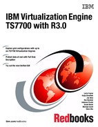
Figure 4-5 on page 152 shows a complete diagram that includes the type and model of common DWDM and FICON Director products other than Shortwave and Longwave specifications. Although not shown in this diagram, FICON Directors and director cascading are supported (see 4.3.3, “FICON Director support” on page 152).
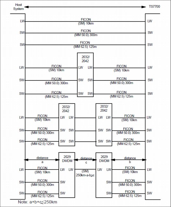
Figure 4-5 System z host attachment distances
4.3.3 FICON Director support
All FICON Directors are supported for single and multicluster grid configurations with
1 Gbps, 2 Gbps, 4 Gbps, or 8 Gbps links. The components will auto-negotiate to the highest speed allowed.
1 Gbps, 2 Gbps, 4 Gbps, or 8 Gbps links. The components will auto-negotiate to the highest speed allowed.
You cannot mix different vendors, such as Brocade (formerly McData, CNT, and InRange) and CISCO, but you can mix models of one vendor.
See the System Storage Interoperation Center (SSIC) for specific intermix combinations supported.
You can find the SSIC at the following URL:
The FICON switch support matrix is at the following address:
4.3.4 FICON channel extenders
FICON channel extenders can operate in one of the following modes:
•Frame shuttle or tunnel mode
•Emulation mode
Using the frame shuttle or tunnel mode, the extender receives and forwards FICON frames without performing any special channel or control unit emulation processing. The performance is limited to the distance between the sites and the normal round-trip delays in FICON channel programs.
Emulation mode can go unlimited distances, and it monitors the I/O activity to devices. The channel extender interfaces emulate a control unit by presenting command responses and channel enablement (CE)/Device End (DE) status ahead of the controller and emulating the channel when running the pre-acknowledged write operations to the real remote tape device. Therefore, data is accepted early and forwarded to the remote device to maintain a full pipe throughout the write channel program.
The supported channel extenders between the System z host and the TS7700 Virtualization Engine are in the same matrix as the FICON switch support under the following URL (see the FICON Channel Extenders section):
Figure 4-6 on page 154 shows an example of host connectivity using FICON channel extenders and cascaded switches.

Figure 4-6 Host connectivity with FICON channel extenders and cascaded switches
4.3.5 Cascaded switches
The following list summarizes the general configuration rules for configurations with cascaded switches:
•Director Switch ID
This is defined in the setup menu.
The inboard Director Switch ID is used on the SWITCH= parameter in the CHPID definition. The Director Switch ID does not have to be the same as the Director Address. Although the example uses a different ID and address for clarity, keep them the same to reduce configuration confusion and simplify problem determination work.
Allowable Director Switch ID ranges have been established by the manufacturer:
– McDATA range: x'61' to x'7F'
– CNT/Inrange range: x'01' to x'EF'
– Brocade range: x'01' to x'EF'
•Director Address
This is defined in the Director GUI setup.
The Director Domain ID is the same as the Director Address that is used on the LINK parameter in the CNTLUNIT definition. The Director Address does not have to be the same as the Director ID, but again, keep them the same to reduce configuration confusion and simplify PD work.
The following allowable Director Address ranges are established by the manufacturer:
– McDATA range: x'61' to x'7F'
– CNT/Inrange range: x'01' to x'EF'
– Brocade range: x'01' to x'EF'
•Director Ports
The Port Address might not be the same as the Port Number. The Port Number identifies the physical location of the port, and the Port Address is used to route packets.
The Inboard Director Port is the port to which the CPU is connected. The Outboard Director Port is the port to which the control unit is connected. It is combined with the Director Address on the LINK parameter of the CNTLUNIT definition:
– Director Address (hex) combined with Port Address (hex): two bytes
– Example: LINK=6106 indicates a Director Address of x'61' and a Port Address of x'06'
•External Director connections:
– Inter-Switch Links (ISLs) connect to E Ports.
– FICON channels connect to F Ports.
•Internal Director connections
Port type and port-to-port connections are defined using the available setup menu in the equipment. Figure 4-7 shows an example of host connection using DWDM and cascaded switches.

Figure 4-7 Host connectivity using DWDM and cascaded switches
4.4 High availability grid considerations
The TS7700 Virtualization Engine grid provides configuration flexibility to meet a variety of needs. Those needs depend on both your needs and the application. This section specifically addresses planning a two-cluster grid configuration to meet high availability needs. However, the discussion easily translates to a three-cluster grid configuration with two production clusters of high availability and disaster recovery. The third cluster is strictly a disaster recovery site.
High availability means being able to provide continuous access to logical volumes through planned and unplanned outages with as little user impact or intervention as possible. It does not mean that all potential for user impact or action is eliminated. The following guidelines relate to establishing a grid configuration for high availability:
•The production systems (sysplexes and LPARs) have FICON channel connectivity to both clusters in the grid. The Data Facility Storage Management Subsystem (DFSMS) library definitions and input/output definition file (IODF) have been established and the appropriate FICON Directors, DWDM attachments, and fiber are in place. Virtual tape devices in both clusters in the grid configuration are varied online to the production systems. If virtual tape device addresses are not normally varied on to both clusters, the virtual tape devices to the standby cluster need to be varied on in a planned or unplanned outage to allow production to continue.
•For the workload placed on the grid configuration, when using only one of the clusters, performance throughput needs to be sufficient to meet service level agreements (SLAs). If both clusters are normally used by the production systems (the virtual devices in both clusters are varied online to production), in the case where one of the clusters is unavailable, the available performance capacity of the grid configuration can be reduced by up to one half.
•For all data that is critical for high availability, consider using a Management Class whose Copy Consistency Point definition has both clusters having a Copy Consistency Point of RUN (immediate copy) or SYNC (sync mode copy). Therefore, each cluster has a copy of the data when the volume is closed and unloaded from the source cluster for immediate copy or both clusters have copies written at the same time with Synchronous mode copy.
•Applications, such as DFSMShsm and DFSMSdfp OAM Object Support, other applications that use dataset-style stacking, or any host application that requires zero recovery point objective (RPO) at sync point granularity can benefit from Synchronous mode copy (SMC). The copy will be updated at the same time as the original volume, keeping both instances of this logical volume synchronized at the record level. See Chapter 2, “Architecture, components, and functional characteristics” on page 15 for a detailed description.
•The distance of grid links between the clusters might influence the grid link performance. Job execution times using Synchronous or Immediate mode might be affected by this factor. Low-latency directors, switches, or DWDMs might help to optimize the network performance. Avoid network quality of service (QoS) or other network sharing methods because they can introduce packet loss, which directly reduces the effective replication bandwidth between the clusters.
•For data for which you want two copies, but the copy operation can be deferred, the Copy Consistency Points for the two production clusters that have the online virtual devices need to be set to Deferred (DD) for both clusters. This, together with the Prefer Local Cluster for Fast Ready Mounts override, will provide the best performance.
•To prevent remote TVC accesses during scratch mounts, the Prefer Local Cluster for Fast Ready Mounts copy override setting must be configured on both TS7700 Virtualization Engine clusters within the grid. See 10.4, “Virtual Device Allocation in z/OS with JES2” on page 673.
•To improve performance and take advantage of cached versions of logical volumes, do not configure the Prefer Local Cluster for Non-Fast Ready Mounts and Force Local Copy Override settings in either cluster. This setting is suggested for homogeneous TS7720 (disk-only) grids. See 10.4, “Virtual Device Allocation in z/OS with JES2” on page 673.
•To minimize operator actions when a failure has occurred in one of the clusters that makes it unavailable, set up the AOTM to automatically place the remaining cluster in at least the read ownership takeover mode. Use read/write ownership takeover mode if you want to modify existing tapes or if you think that your scratch pool might not be large enough without using those scratch volumes owned by the downed cluster. If AOTM is not used, or it cannot positively determine if a cluster has failed, an operator must determine whether a cluster has failed and, through the management interface on the remaining cluster, manually select one of the ownership takeover modes.
•If multiple grid configurations are available for use by the same production systems, you can optionally remove the grid that experienced an outage from the Storage Group for scratch allocations. This will direct all scratch allocations to fully functional grids while still allowing reads to access the degraded grid. This approach might be used if the degraded grid cannot fully complete the required replication requirements. Only use this approach for read access.
By following these guidelines, the TS7700 Virtualization Engine grid configuration supports the availability and performance goals of your workloads by minimizing the impact of the following outages:
•Planned outages in a grid configuration, such as microcode or hardware updates to a cluster. While one cluster is being serviced, production work continues with the other cluster in the grid configuration after virtual tape device addresses are online to the cluster.
•Unplanned outage of a cluster. For the logical volumes with an Immediate or Synchronous Copy policy effective, all jobs that completed before the outage will have a copy of their data available on the other cluster. For jobs that were in progress on the cluster that failed, they can be reissued after virtual tape device addresses are online on the other cluster (if they were not already online) and an ownership takeover mode has been established (either manually or through AOTM). If it is necessary, access existing data to complete the job. For more details about AOTM, see “Autonomic Ownership Takeover Manager” on page 77. For jobs that were writing data, the written data is not accessible and the job must start again.
|
Important: Scratch (Fast Ready) categories and Data Classes definitions are defined at the system level. Therefore, if you modify them in one cluster, it will apply to all clusters in that grid.
|
4.5 Planning for software implementation
This section provides information for planning tasks related to host configuration and software requirements for use with the TS7700 Virtualization Engine.
4.5.1 Host configuration definition
You must define the hardware to the host using the hardware configuration definition (HCD) facility. Specify the LIBRARY-ID and LIBPORT-ID in your HCD/input/output configuration program (IOCP) definitions even in a stand-alone configuration.
LIBRARY-ID
In a grid configuration used with the TS7700 Virtualization Engine, each virtual device attached to a System z host reports back the same five-character hexadecimal library sequence number, known as the composite library ID. With the composite library ID, the host considers the grid configuration as a single library.
Each cluster in a grid configuration possesses a unique five-character hexadecimal Library Sequence Number, known as the distributed library ID, which identifies it among the clusters in its grid. This distributed library ID is reported to the System z host upon request and is used to distinguish one cluster from another in a specific grid.
LIBPORT-ID
Each logical control unit, or 16-device group, must present a unique subsystem identification to the System z host. This ID is a 1-byte field that uniquely identifies each logical control unit within the cluster and is called the LIBPORT-ID. The value of this ID cannot be 0. Table 4-10 shows the definitions of the LIBPORT-IDs in a multicluster grid.
For more details, see 6.1.4, “Library names, Library IDs, and port IDs” on page 288.
Table 4-10 Subsystem identification definitions
|
Cluster
|
Logical CU (hex)
|
LIBPORT-ID (hex)
|
|
0
|
0 - F
|
01 - 10
|
|
1
|
0 - F
|
41 - 50
|
|
2
|
0 - F
|
81 - 90
|
|
3
|
0 - F
|
C1 - D0
|
|
4
|
0 - F
|
21 - 30
|
|
5
|
0 - F
|
61 - 70
|
Virtual tape drives
The TS7700 Virtualization Engine presents a tape drive image of a 3490 C2A, identical to the VTS and Peer-to-Peer (PTP) subsystems. Command sets, responses to inquiries, and accepted parameters match the defined functional specifications of a 3490E drive.
Each TS7700 Virtualization Engine cluster provides 256 virtual devices. When two clusters are connected in a grid configuration, the grid provides 512 virtual devices. When three clusters are connected to a grid configuration, the grid provides up to 768 virtual devices and so on up to six clusters in a grid configuration, which can provide 1536 virtual devices.
4.5.2 Software requirements
The TS7700 Virtualization Engine is supported with the following operating system levels:
• z/OS V1R12, or later (lower release level support considered through RPQ process)
See APAR OA32957 for additional information about the support being provided for Release 2.0 of the TS7700. The new scratch allocation assist support is only being provided in the non-JES3 (JES2) environment.
See APAR OA37267 for additional information about the support being provided for Release 2.1 of the TS7700. No additional host software support was provided for Release 3.0 of the TS7700.
In general, install the host software support. See the “VTS”, “PTP”, and “3957” PSP buckets from the IBM Support and Downloads link for the latest information about Software Maintenance.
•IBM z/VM® V5.4.0, or later
With z/VM, the TS7740 and TS7720 are transparent to host software. z/VM V5R4 or later is required for both guest and native VM support. DFSMS/VM Function Level 221 with the PTF for APARs VM65005 and VM64773 is required for native VM tape library support. Environmental Record Editing and Printing (EREP) V3.5 plus PTFs are required.
•IBM z/VSE® V4.3, or later
With z/VSE, the TS7740 and TS7720 are transparent to host software. z/VSE supports the TS7740 and the TS7720 as a stand-alone system in transparency mode. z/VSE 5.1 supports multicluster grid and Copy Export.
•z/TPF V1.1, or later
With z/TPF, the TS7740 and TS7720 are supported in both a single node and a grid environment with the appropriate software maintenance. The category reserve and release functions are not supported by the TS7700 Virtualization Engine.
4.5.3 z/OS software environments
System-managed tape allows you to manage tape volumes and tape libraries according to a set of policies that determine the kind of service to be given to the data sets on the volume.
The automatic class selection (ACS) routines process every new tape allocation in the system-managed storage (SMS) address space. The production ACS routines are stored in the active control data set (ACDS). These routines allocate to each volume a set of classes that reflect your installation’s policies for the data on that volume. The ACS routines are invoked for every new allocation. Tape allocations are passed to the object access method (OAM), which uses its Library Control System (LCS) component to communicate with the Integrated Library Manager.
The Storage Class ACS routine determines whether a request is SMS-managed. If no Storage Class is assigned, the request is not SMS-managed, and allocation for non-specific mounts is made outside the tape library.
For SMS-managed requests, the Storage Group routine assigns the request to a Storage Group. The assigned Storage Group determines which logical partitions in the tape library are to be used. Through the Storage Group construct, you can direct logical volumes to specific physical volume pools.
In addition to defining new SMS classes in z/OS, the new SMS classes must be defined in the TS7700 Virtualization Engine through the management interface (MI). This way, the name is created in the list and the default parameters are assigned to it. Figure 4-8 shows the default Management Class in the first line and another Management Class defined as described in the second line.

Figure 4-8 Default construct
4.5.4 Sharing and partitioning considerations
If you plan to connect sysplexes and even DR sites, it is better to decide in advance which scratch categories to assign to which sysplex. Table 4-11 shows an example of scratch categories assignment in a multi-sysplex center.
Table 4-11 Scratch category assignment
|
PROD1
|
PROD2
|
PRE-PROD
|
TEST
|
DR site
|
|
0002
|
0012
|
0022
|
0032
|
0042
|
Partitioning the physical media (TS7740) between multiple hosts
The virtual drives and virtual volumes in a TS7700 Virtualization Engine can be partitioned just like physical drives and real volumes. Any virtual volume can go to any physical stacked volume when using a TS7740. The TS7700 Virtualization Engine places no restrictions on the use and management of those resources. When using a TS7740, you have the ability to partition your stacked media in up to 32 separate pools, by assigning a Storage Group to a defined range of stacked volumes before insertion time.
Sharing a TS7700 Virtualization Engine
A FICON-attached TS7700 Virtualization Engine supports two or four physical channels, each of which is capable of supporting 256 logical paths. Each logical path can address any of the 256 virtual devices in the TS7700 Virtualization Engine.
Use a FICON Director when connecting the TS7700 Virtualization Engine to more than one system when the maximum number of FICON ports per system is required.
The TS7700 Virtualization Engine places no limitations on the number of hosts that can use those channel paths or the types of hosts, or their operating system environments - within the limit of 256 logical paths per port. After it exceeds 256 logical paths per port, no additional paths can be established. This is the same as for any tape technologies that are supported in IBM Tape Libraries.
An operating environment, however, through its implementation, imposes limits. z/OS DFSMS can support up to 32 systems or groups of systems per source control data set (SCDS).
Anything that can be done with native drives in an IBM Tape Library can be done with the virtual drives in a TS7700 Virtualization Engine.
The TS7700 Virtualization Engine attaches to the host system or systems through two or four FICON channels. Each FICON channel provides 256 logical paths (starting with TS7700 Virtualization Engine Release 1.4). A four-FICON configuration results in a total of 1024 logical paths for each TS7700 Virtualization Engine.
For more information, see 6.1.3, “Logical path considerations” on page 287.
|
Important: Scratch (Fast Ready) categories and Data Class definitions are defined at the system level. Therefore, if you modify them in one cluster, it will apply to all clusters in that grid.
|
Partitioning the TS770 with selective device access control (SDAC)
Selective device access control (SDAC) allows exclusive access to one or more VOLSER ranges by only certain logical control units or subsystem IDs within a composite library for the purpose of host-initiated mounts, ejects, and changes to attributes or categories.
You can use SDAC to configure hard partitions at the LIBPORT-ID level for independent host LPARs or system complexes. Hard partitioning prevents a host logical partition or system complex with an independent tape management configuration from inadvertently modifying or removing data owned by another host. It also prevents applications and users on one system from accessing active data on volumes owned by another system.
SDAC is enabled using FC 5271, Selective Device Access Control. See “TS7700 Virtualization Engine common feature codes” on page 134 for additional information about this feature. This feature license key must be installed on all clusters in the grid before SDAC is enabled. You can specify one or more LIBPORT-IDs per SDAC group. Each access group is given a name and assigned mutually exclusive VOLSER ranges. Use the Library Port Access Groups window on the TS7700 Virtualization Engine management interface to create and configure Library Port Access Groups for use with SDAC. Access control is imposed as soon as a VOLSER range is defined. As a result, selective device protection applies retroactively to pre-existing data. See 6.4, “Implementing Selective Device Access Control” on page 311 for detailed implementation information.
A case study about sharing and partitioning the TS7700 Virtualization Engine is in Appendix E, “Case study for logical partitioning of a two-cluster grid” on page 905.
4.6 Planning for logical and physical volumes
Before you define logical volumes to the TS7700 Virtualization Engine, consider the total number of logical volumes required, the volume serial ranges to define, and the number of volumes within each range.
The VOLSERs for logical volumes and physical volumes must be unique.
The VOLSERs must be unique throughout an SMSplex and throughout all storage hierarchies, such as DASD, tape, and optical storage media. It must also be unique across LPARs connected to the grid.
4.6.1 Logical volumes
Determine the number of logical volumes that are required to handle the workload that you are planning for the TS7700 Virtualization Engine. The default number of logical volumes supported is 1,000,000. You can add support for additional logical volumes in 200,000 volume increments (FC5270), up to a total of 4,000,000 logical volumes.
|
Tip: For 3957-V06/VEA, the limit is 2,000,000 logical volumes.
|
The TS7700 Virtualization Engine provides support for logical WORM (LWORM) volumes.
Consider the size of your logical volumes, the number of scratch volumes you will need per day, the time that is required for return-to-scratch processing, how often scratch processing is performed, and whether you need to define logical WORM volumes.
Size of logical volumes
The TS7700 Virtualization Engine supports logical volumes with maximum sizes of 400, 800, 1000, 2000, 4000, and 6000 MiB, although effective sizes can be larger if data is compressed. For example, if your data compresses with a 3:1 ratio, the effective maximum logical volume size for a 6,000 MiB logical volume is 18,000 MB.
|
Tip: Support for 25,000 MiB logical volume maximum size is available by RPQ on TS7720-only clusters and supported by a code level of 8.7.0.143 or higher.
|
Depending on the logical volume sizes that you choose, you might see the number of volumes required to store your data grow or shrink depending on the media size from which you are converting. If you have data sets that fill native 3590 volumes, even with 6,000 MB logical volumes, you will need more TS7700 Virtualization Engine logical volumes to store the data, which will be stored as multi-volume data sets.
The 400 MB CST-emulated cartridges or 800 MB with ECCST-emulated cartridges are the two types you can specify when adding volumes to the TS7700 Virtualization Engine. You can use these sizes directly or use policy management to override them to provide for the 1,000, 2,000, 4,000, or 6,000 MB sizes.
A logical volume size can be set by VOLSER and can change dynamically using the DFSMS Data Class storage construct when a job requires a scratch volume. The amount of data copied to the stacked cartridge is only the amount of data that has been written to a logical volume. The choice between all available logical volume sizes does not affect the real space used in either the TS7700 Virtualization Engine cache or the stacked volume.
In general, unless you have a special need for CST emulation (400 MB), specify the ECCST media type when inserting volumes in the TS7700 Virtualization Engine.
In planning for the number of logical volumes needed, first determine the number of private volumes that make up the current workload you will be migrating. One way to do this is by looking at the amount of data on your current volumes and then matching that to the supported logical volume sizes. Match the volume sizes, taking into account the compressibility of your data. If you do not know the average ratio, use the conservative value of 2:1.
If you choose to only use the 800 MB volume size, the total number needed might increase depending on whether current volumes that contain more than 800 MB compressed need to expand to a multi-volume set. Take that into account for planning the number of logical volumes required.
Now that you know the number of volumes you need for your current data, you can estimate the number of empty scratch logical volumes you must add. Based on your current operations, determine a nominal number of scratch volumes from your nightly use. If you have an existing VTS installed, you might have already determined this number and are able to set a scratch media threshold with that value through the ISMF Library Define window.
Next, multiply that number by the value that provides a sufficient buffer (typically 2×) and by the frequency with which you want to perform returns to scratch processing.
A following formula is suggested to calculate the number of logical volumes needed:
Vv = Cv + Tr + (Sc)(Si + 1)
The formula contains the following values:
Vv Total number of logical volumes needed
Cv Number of logical volumes needed for current data rounded up to the nearest 10,000
Tr Threshold value from the ISMF Library Define window for the scratch threshold for the media type used (normally MEDIA2), usually set to equal the number of scratch volumes used per night
Sc Number of empty scratch volumes used per night, rounded up to the nearest 500
Si Number of days between scratch processing (return-to-scratch) by the tape management system
For example, assuming the current volume requirements (using all the available volume sizes), using 2,500 scratch volumes per night, and performing return-to-scratch processing every other day, you need to plan on the following number of logical volumes in the TS7700 Virtualization Engine:
75,000 (current, rounded up) + 2,500 + (2,500) (1+1) = 82,500 logical volumes
If you plan to use the expired-hold option, take the maximum planned hold period into account when calculating the Si value in the previous formula.
If you define more volumes than you need, you can always delete the additional volumes. Unused logical volumes do not consume space.
The default number of logical volumes supported by the TS7700 Virtualization Engine is 1,000,000. You can add support for additional logical volumes in 200,000 volume increments, up to a total of 4,000,000 logical volumes. This is the maximum number either in a stand-alone or grid configuration.
|
Tip: For 3957-V06/VEA, the limit is 2,000,000 logical volumes.
|
See FC 5270, Increased logical volumes, in “TS7700 Virtualization Engine common feature codes” on page 134 to achieve this upgrade.
|
Consideration: Up to 10,000 logical volumes can be inserted at one time. Attempting to insert over 10,000 logical volumes at one time will return an error.
|
Number of scratch volumes needed per day
As you run your daily production workload, you will need enough logical volumes in SCRATCH status to support the data that will be written to the TS7700 Virtualization Engine. This can be hundreds or thousands of volumes, depending on your workload. You will likely want more than one day’s worth of scratch volumes available at any point in time.
Return-to-scratch processing
Return-to-scratch processing involves running a set of tape management tools that identify the logical volumes that no longer contain active data, and then communicating with the TS7700 Virtualization Engine to change the status of those volumes from private to scratch. The amount of time the process takes depends on the type of tape management system being employed, how busy the TS7700 Virtualization Engine is when it is processing the volume status change requests, and whether a grid configuration is being used.
You can see elongated elapsed time in any Tape Management Systems return-to-scratch process when you migrate to or install a multicluster configuration solution.
If the number of logical volumes used on a daily basis is small (fewer than a few thousand), you might choose to only perform return-to-scratch processing every few days. A good rule is to plan for no more than a 4-hour time period to run return to scratch. By ensuring a nominal run time of four hours, enough time exists during first shift to run the process twice if problems are encountered during the first attempt. Unless there are specific reasons, execute return-to-scratch processing once per day.
With z/OS V1.9 or later, return to scratch in DFSMSrmm has been enhanced to speed up this process. To reduce the time required for housekeeping, it is now possible to run several return-to-scratch processes in parallel. For additional information about the enhanced return-to-scratch process, see the z/OS DFSMSrmm Implementation and Customization Guide, SC26-7405.
|
Tip: The expire-hold option might delay the time that the scratch volume becomes usable again, depending on the defined hold period.
|
Volume serial numbering
When you insert volumes, you do that by providing starting and ending volume serial number range values.
The TS7700 Virtualization Engine determines how to establish increments of VOLSER values based on whether the character in a particular position is a number or a letter. For example, inserts starting with ABC000 and ending with ABC999 will add logical volumes with VOLSERs of ABC000, ABC001, ABC002…ABC998, and ABC999 into the inventory of the TS7700 Virtualization Engine. You might find it helpful to plan for growth by reserving multiple ranges for each TS7700 Virtualization Engine you expect to install.
If you have multiple partitions, it is better to plan in advance which ranges will be used in which partitions, for example, A* for the first sysplex, B* for the second sysplex, and so on. If you need more than a range, you can select A* and B* for the first sysplex, C* and D* for the second sysplex, and so on.
4.6.2 Logical WORM (LWORM)
TS7700 Virtualization Engine supports the logical Write Once, Read Many (WORM) function through TS7700 Virtualization Engine software emulation. The logical WORM enhancement can duplicate most of the 3592 WORM behavior. The host views the TS7700 Virtualization Engine as an LWORM-compliant library that contains WORM-compliant 3490E logical drives and media.
4.6.3 Physical volumes for TS7740 Virtualization Engine
Determine the number of physical volumes that are required to accommodate the workload you are planning for the TS7700 Virtualization Engine. Consider the following information:
•The number of logical volumes you define
•The average amount of data on a volume
•The average compression ratio achieved for the data
•If the Selective Dual Copy function is to be used
•Whether the Delete Expired Volume Data setting is to be used
•Whether the Copy Export function is to be used
•The reclaim threshold settings, scratch physical volumes, and the number of physical volume pools
Ordering new tape cartridges
Order new physical cartridges with consideration for the complete fulfilment cycle. New cartridges can be ordered that are already labeled with a specified bar code range representing the volume ID (VOLID).
Reuse of existing cartridges
Reuse of existing 3592 cartridges is permitted. However, the cartridges must be re-initialized prior inserting them into the TS7740 to ensure that the external bar code label matches the internal VOLID. If the external label does not match the internal label, the cartridge is rejected.
Number of logical volumes
Because the data on a logical volume is stored on a physical volume, the number of logical volumes used has a direct effect on the number of physical volumes required. The default number of logical volumes supported is 1,000,000. You can add support for additional logical volumes in 200,000 volume increments (FC5270), up to a total of 4,000,000 logical volumes. The total number of logical volumes supported in a multicluster grid configuration is determined by the cluster with the lowest number of Feature Code 5270 installed.
Average amount of data on a volume
The TS7700 Virtualization Engine only stores the amount of data you write to a logical volume, plus a small amount of metadata.
Average compression ratio achieved for the data
The data that a host writes to a logical volume might be compressible. The space required on a physical volume is determined after the results of compression. If you do not know the average compression ratio for your data, assume a conservative 2:1 ratio.
Selective Dual Copy function
If you use this function for some or all of your data, a second physical copy of the data is written to a physical volume.
For critical data that only resides on tape, you can currently make two copies of the data on physically separate tape volumes either manually through additional job steps or through their applications. Within a TS7700 Virtualization Engine, you might need to be able to control where a second copy of your data is placed so that it is not stacked on the same physical tape as the primary copy. Although this can be accomplished through the logical volume affinity functions, it simplifies the management of the tape data and is a better use of the host CPU resources to have a single command to the TS7700 Virtualization Engine subsystem to direct it to selectively make two copies of the data contained on a logical volume.
If you activate Dual Copy for a group of data or a specific pool, consider that all tasks and properties, which are connected to this pool, are duplicated:
•The number of reclamation tasks
•The number of physical drives used
•The number of cartridges used
•The number of writes to the cartridges: One from cache to the primary pool and another to the backup pool
You must plan for additional throughput and capacity. You do not need more logical volumes because the second copy uses an internal volume ID.
Number of Copy Export volumes
If you are planning to use the Copy Export function, plan for a sufficient number of physical volumes for the Copy Export function and sufficient storage cells for the volumes in the library destined for Copy Export or in the Copy Export state. The Copy Export function defaults to a maximum of 2,000 physical volumes in the Copy Export state. This number includes offsite volumes, the volumes still in the physical library that are in the Copy Export state, and the empty, filling, and full physical volumes that will eventually be set to the Copy Export state. With R1.6 and later, the default value can be adjusted through the management interface to a maximum value of 10,000. After your Copy Export operations reach a steady state, approximately the same number of physical volumes is being returned to the library for reclamation as there are those being sent offsite as new members of the Copy Export set of volumes.
Delete Expired Volume Data setting
If the Delete Expired Volume Data setting on the management interface is not used, logical volumes occupy space on the physical volumes even after they have been returned to scratch. In that case, only when a logical volume is rewritten is the old data released to reduce the amount of active data on the physical volume.
With the Delete Expired Volume Data setting, the data associated with volumes that have been returned to scratch is deleted after a time period and their old data is released. For example, assume that you have 20,000 logical volumes in SCRATCH status at any point in time, the average amount of data on a logical volume is 400 MB, and the data compresses at a 2:1 ratio. The space occupied by the data on those scratch volumes is 4,000,000 MBs or the equivalent of 14 JA cartridges (when using J1A emulation mode). By using the Delete Expired Volume Data setting, you can reduce the number of cartridges required in this example by 14.
Reclaim threshold settings
The number of physical volumes also depends on the Reclaim Threshold Percentage that you have specified for the minimum amount of active data on a volume before it becomes eligible for reclamation. The default is set to 10%. The reclaim threshold setting can have a large impact on the number of physical volumes required. Physical volumes will hold between the threshold value and 100% of data. On average, the percentage of active data on the physical volume is (100% + 10%)/2 or 55% (assuming a reclamation setting of 10%).
Having too low a setting results in more physical volumes being needed. Having too high a setting might affect the ability of the TS7740 Virtualization Engine to perform the host workload, because it is using its resources to perform reclamation. You might need to experiment to find a threshold that matches your needs.
As a good starting point, use 25%. This will accommodate most installations.
Number of physical volume pools
Plan for at least 10 scratch physical volumes to be available in the common scratch pool.
For each physical volume pool you are planning to use, have at least three scratch physical volumes. These are in addition to the number of physical volumes calculated to hold the data on the logical volumes.
The following formula is suggested to calculate the number of physical volumes needed:
Pv = (((Lv + Lc) × Ls/Cr)/(Pc × (((100+Rp)/100)/2))
The formula contains the following values:
Pv Total number of physical volumes needed
Lv Number of logical volumes defined
Lc The number of logical volumes that will be dual-copied
Ls The average logical volume size in MB
Cr Compression ratio of your data
Rp The reclamation percentage
Pc Capacity of a physical volume in MB
To this number, you then add scratch physical volumes based on the common media pool and the number of physical volume pools you plan to use. For example, use the following assumptions:
Lv 82,500 (see “Number of logical volumes” on page 165)
Lc 10,000 (logical volumes)
Ls 400 MB
Cr 2
Rp 10
Pc 300,000 MB (capacity of a 3592 J1A written JA volume)
500,000 MB (capacity of a TS1120 written JA volume)
700,000 MB (capacity of a TS1120 written JB volume)
640,000 MB (capacity of a TS1130 written JA volume)
500,000 MB (capacity of a TS1120 written JA volume)
700,000 MB (capacity of a TS1120 written JB volume)
640,000 MB (capacity of a TS1130 written JA volume)
1,000,000 MB (capacity of a TS1130 written JB volume)
1,600,000 MB (capacity of a TS1140 written JB volume)
4,000,000 MB (capacity of a TS1140 written JC volume)
Common scratch pool 10
Volume pools 5 (with three volumes per pool)
|
Important: The calculated number is the required minimum value. It does not include any spare volumes to allow data growth from the first installation phase.
Therefore, add enough extra scratch volumes for future data growth.
|
Using the suggested formula and the assumptions, plan to use the following number of physical volumes in your TS7740 Virtualization Engine:
(((82,500 + 10,000) × 400 MB)/2)/(300,000 × (((100 + 10)/100)/2)) + 10 + 5 × 3 = 137 physical volumes
If you insert more physical volumes in the TS7740 Virtualization Engine than you need, you can eject them at a later time.
Pooling considerations
Pooling might have an effect on the throughput of your TS7740 Virtualization Engine. If you are using physical volume pooling at your site, consider the following possibilities:
•The possible increase of concurrent tape drive usage within the TS7740 Virtualization Engine
Depending on the number of pools and the amount of logical volume data being created per pool, you need to ensure that sufficient drives are available to handle:
– Premigration of logical volumes from the TVC
– Recall of logical volumes from physical stacked volumes to the TVC
– The amount of logical volume data being dual copied
•The reclamation process
Reclamation is done at the pool level and each reclamation task will use two drives. To minimize the effects of the reclamation process, ensure that you maintain a sufficient number of physical TS7740 Virtualization Engine scratch cartridges so that the reclamation process is performed within the reclaim scheduled time.
•An increase in the number of cartridges being used
•Library slot capacity
•TS7740 Virtualization Engine processing/cache capacity
Out of scratch for physical stacked volumes
Monitor the number of empty stacked volumes in a library. If the library is close to running out of a physical volume media type, take actions to either expedite the reclamation of physical stacked volumes or add additional ones. The Host Console Request function can be used to obtain the physical volume counts within the TS7740 Virtualization Engine. You can also use the Bulk Volume Information Retrieval (BVIR) function to obtain the physical media counts for each library. The information obtained includes the empty physical volume counts by media type for the common scratch pool and each defined pool.
See “Out of Physical Volumes” on page 636 for more information about how to handle an out of scratch situation. For more information about BVIR, see Table 10.9.5 on page 735. For more information about the Host Console Request function, see IBM Virtualization Engine TS7700 Series z/OS Host Command Line Request User’s Guide, WP101091, available at this website:
4.6.4 Data compression
When writing data to a virtual volume, the host compression definition is honored. Compression is turned on or off by the JCL parameter DCB=TRTCH=COMP (or NOCOMP), the Data Class parameter COMPACTION=YES|NO, or the COMPACT=YES|NO definition in the DEVSUPxx PARMLIB member. The TRTCH parameter overrides the Data Class definition and both override the PARMLIB definition.
|
Important: To achieve the optimum throughput, verify your definitions to ensure that you specified compression for data written to the TS7700 Virtualization Engine.
|
4.6.5 Secure Data Erase function
Expired data on a physical volume remains readable until the volume has been completely overwritten with new data. Some clients prefer to delete the content of a reclaimed stacked cartridge, due to security or business requirements.
TS7740 Virtualization Engine implements the Secure Data Erasure on a pool basis. With the Secure Data Erase function, all reclaimed physical volumes in that pool are erased by writing a random pattern across the whole tape before reuse. In the case of a physical volume that has encrypted data, the erasure is accomplished by deleting encryption keys on the volume, rendering the data unrecoverable on this cartridge. A physical cartridge is not available as a scratch cartridge as long as its data is not erased.
|
Consideration: If you choose this “erase” functionality and you are not using tape encryption, TS7740 Virtualization Engine needs a lot of time to reclaim every physical tape. Therefore, the TS7740 Virtualization Engine will need more time and more back-end drive activity every day to perform reclamation and erase the reclaimed cartridges afterward. With tape encryption, the Secure Data Erase functionality is relatively fast.
|
The Secure Data Erase function also monitors the age of expired data on a physical volume and compares it with the limit set by the user in the policy settings. Whenever the age exceeds the limit defined in the pool settings, the Secure Data Erase function forces a reclaim and subsequent erasure of the volume.
See 2.3.30, “Secure Data Erase” on page 76 and 5.3.4, “Defining physical volume pools (TS7740 Virtualization Engine)” on page 217 for more details about the Secure Data Erase function.
4.6.6 Copy Policy Override settings
For selected TS7700 Virtualization Engine clusters, you can tailor some parameters to override established copy policies or I/O operations, influencing the behavior of that cluster in selecting I/O TVC and replication responses. The settings are specific to a cluster in a multicluster grid configuration, which means that each cluster can have separate settings if you want. The settings take effect for any mount requests that are received after the settings were saved. Mounts already in progress are not affected by a change in the settings. You can define and set the following settings:
•Prefer local cache for Fast Ready mount requests
•Prefer local cache for non-Fast Ready mount requests
•Force volumes mounted on this cluster to be copied to the local cache
•Allow fewer RUN consistent copies before reporting the RUN command complete
•Ignore cache preference groups for copy priority
Use the available settings to meet specific performance and availability objectives. For more details about Copy Policy Override, refer to“Define Copy Policy Override settings” on page 267.
|
Important: In an IBM Geographically Dispersed Parallel Sysplex (IBM GDPS), select the Force Local Volume override on each cluster to ensure that wherever the GDPS primary site is, this TS7700 Virtualization Engine Cluster is preferred for all I/O operations.
When operating GDPS in primary mode (tape virtual devices online for the host only at the primary site) and the TS7700 Virtualization Engine cluster of the GDPS primary site fails, perform the following recovery actions:
•Vary virtual devices from a remote TS7700 Virtualization Engine cluster online from the primary site of the GDPS host.
•Manually invoke, through the TS7700 Virtualization Engine management interface, a Read/Write Ownership Takeover, unless Automated Ownership Takeover Manager (AOTM) has already transferred ownership.
|
4.6.7 Planning for cache thresholds and removal policies for a TS7720 cluster
The TS7720 Virtualization Engine does not attach to a physical tape library; therefore, its capacity is limited by the size of its disk cache.
The most important aspect of managing the cache in the TS7720 is to avoid the cache full state (less than 1 TB of free space in cache). In the out-of-cache state, this cluster will not accept writes into its disk cache. Specific mounts for reading existing volumes are still allowed. A Read Modify will fail.
New scratch (Fast Ready) mounts will choose alternate TS7700 Tape Volume Cache options in the grid. During TVC selection, a TS7720 (including the mount point), which is full, is viewed as an invalid TVC candidate. Only when all other candidates (TS7720 or TS7740 in the grid) are also invalid will the new scratch (Fast Ready) mount fail. At this point, it will be necessary to eject existing volumes from the virtual library to regain cache space.
The user must plan the amount of data stored in a TS7720 cluster, keeping it below the limit imposed by the cache size. When a TS7720 is in a stand-alone configuration, the cache size is the absolute limit for the data that can be written and held in the virtual tape library. Practices, such as enabling Delete Expire for scratch volumes, can help reduce the chances of reaching a cache-full condition. See more details in 2.2.13, “Expired virtual volumes and Delete Expired function” on page 36. Also, check IBM Virtualization Engine TS7700 Series Best Practices - Cache Management in the TS7720 V1.5, which is available at this website:
The TS7720 Virtualization Engine can be installed as part of a multicluster grid. In this configuration, the TS7720 disk cache usage can be greatly optimized by using cache management policies.
In a multicluster grid environment, the user can establish a threshold of cache usage in the TS7720 cluster. When this threshold level is reached, the set of removal policies allows logical volumes to be automatically removed from cache, as long as there is another consistent copy in the grid. The user can specify which volumes are preferred to be removed first, which are to be kept in cache if possible, or even which ones must be pinned in the TS7720 cache. Check your planning for those management and removal policies, if it applies to your installation.
You can find more details in 5.4.7, “TS7720 cache thresholds and removal policies” on page 274. Also, check IBM Virtualization Engine TS7700 Series Best Practices - Cache Management in the TS7720, which is available at this website:
4.6.8 Planning for tape encryption in the TS7740 Virtualization Engine
The importance of data protection has become increasingly apparent with news reports of security breaches, loss and theft of personal and financial information, and government regulation. Encryption of the physical tapes used by TS7740 helps control the risks of unauthorized data access without excessive security management burden or subsystem performance issues.
Encryption on the TS7740 Virtualization Engine is controlled on a storage pool basis. Storage Group and Management Class DFSMS constructs specified for logical tape volumes determine which physical volume pools are used for the primary and backup (if used) copies of the logical volumes. The storage pools, originally created for the management of physical media, have been enhanced to include encryption characteristics.
The tape encryption solution in TS7740 consists of several components:
•The TS7740 tape encryption solution uses either the Tivoli Key Lifecycle Manager or the IBM Security Key Lifecycle Manager as a central point from which all encryption key information is managed and served to the various subsystems.
•The TS1120, TS1130, or TS1140 encryption-enabled tape drives are the other fundamental piece of TS7740 tape encryption, providing hardware that performs the cryptography function without reducing the data-transfer rate.
|
Tip: The IBM Encryption Key Manager is not supported for use with TS1140 3592-E07 Tape Drives. Either the Tivoli Key Lifecycle Manager or the IBM Security Key Lifecycle Manager is required.
|
•The TS7740 Virtualization Engine provides the means to manage the use of encryption and the keys that are used on a storage-pool basis. It also acts as a proxy between the tape drives and the Tivoli Key Lifecycle Managers or IBM Security Key Lifecycle Managers, using Ethernet to communicate with the Tivoli Key Lifecycle Manager or IBM Security Key Lifecycle Manager and in-band Fibre Channel connections with the drives. Encryption support is enabled with FC9900.
Instead of user-provided key labels per pool, the TS7740 Virtualization Engine can also support the use of Default Keys per pool. After a pool is defined to use the Default Key, the management of encryption parameters is performed at the key manager.
The tape encryption function in a TS7740 Virtualization Engine does not require any host software updates, after the TS7740 Virtualization Engine controls all aspects of the encryption solution.
Although the feature for encryption support is client-installable, check with your IBM SSR for the prerequisites and related settings before you enable encryption on your TS7740 Virtualization Engine.
|
Tip: Pool encryption settings are disabled by default.
|
Encryption Key Managers
The Encryption Key Managers must be installed, configured, and operational before you install the encryption feature on the TS7740 Virtualization Engine.
|
Note: The IBM Encryption Key Manager is not supported for use with TS1140 3592-E07 Tape Drives. Either the Tivoli Key Lifecycle Manager or the IBM Security Key Lifecycle Manager is required.
|
You need to also create the certificates and keys you plan to use for encrypting your backstore tape cartridges.
Despite the fact that it is possible to operate with a single key manager, we strongly advise configuring two key managers for redundancy. Each key manager needs to have all the required keys in its respective keystore. Each key manager must have independent power and network connections to maximize the chances that at least one of them is reachable from the TS7740 Virtualization Engine when needed. If the TS7740 Virtualization Engine is unable to contact either key manager when required, you might temporarily lose access to migrated logical volumes and you will not be able to move logical volumes in encryption-enabled storage pools out of cache.
IBM Encryption Key Manager
IBM Encryption Key Manager is not supported for use with TS1140 3592-E07 Tape drives, and it must not be downloaded for new tape encryption installations. If you are planning for encryption, use either the Tivoli Key Lifecycle Manager or the IBM Security Key Lifecycle Manager.
Tivoli Key Lifecycle Manager
As an enhancement and follow-on to the Encryption Key Manager, the Tivoli Key Lifecycle Manager can be used to encrypt your data with the TS1120, TS1130, and TS1140 tape drives. Like the Encryption Key Manager, the Tivoli Key Lifecycle Manager serves data keys to the tape drive. The first release of Tivoli Key Lifecycle Manager focuses on ease of use and provides a new graphical user interface (GUI) to help with the installation and configuration of the key manager. It also allows for the creation and management of the key encrypting keys (certificates). If you already use the existing Encryption Key Manager, you can migrate easily to the Tivoli Key Lifecycle Manager.
For additional information about the Tivoli Key Lifecycle Manager, see the following URL:
http://publib.boulder.ibm.com/infocenter/tivihelp/v2r1/index.jsp?topic=/com.ibm.tklm.doc/welcome.htm
IBM Security Key Lifecycle Manager
The IBM Security Key Lifecycle Manager for z/OS has been available since April 2011. The IBM Security Key Lifecycle Manager is the latest key manager for z/OS from IBM and removes the dependency on IBM System Services Runtime Environment for z/OS and DB2, which creates a simpler migration from IBM Encryption Key Manager. IBM Security Key Lifecycle Manager manages encryption keys for storage, simplifying deployment and maintaining availability to data at rest natively on the System z mainframe environment. It simplifies key management and compliance reporting for the privacy of data and compliance with security regulations.
Additional information can be obtained from the IBM Security Key Lifecycle Manager website:
Encryption-capable tape drives
Data is encrypted on the back-end tape drives, so the TS7740 Virtualization Engine must be equipped with encryption-capable tape drives, such as these tape drives:
•TS1120 3592- E05 (Encryption-capable) tape drives. Must be running in 3592 E05 native mode. TS1120 tape drives with FC5592 or FC9592 are encryption-capable.
•TS1130 3592- E06 tape drives.
•TS1140 3592-E07 tape drives.
|
Note: Intermixing drive models is not supported by the TS7740 Virtualization Engine.
|
TS7740 Virtualization Engine
FC9900 must be installed to access the encryption settings.
The TS7740 Virtualization Engine must not be configured to force the TS1120 drives into J1A mode. This setting can only be changed by your IBM SSR. If you need to update the microcode level, be sure that the IBM SSR checks and changes this setting, if needed.
Encryption Key Manager IP addresses
The Encryption Key Manager assists encryption-enabled tape drives in generating, protecting, storing, and maintaining encryption keys that are used to encrypt information being written to tape media and decrypting information being read from tape media. It must be available in the network, and TS7740 must be configured with the IP addresses and TCP/IP ports to be able to find the Encryption Key Managers in the network.
For a comprehensive TS7740 Virtualization Engine encryption implementation plan, see “Implementing TS7700 Tape Encryption” in IBM System Storage Tape Encryption Solutions, SG24-7320.
4.6.9 Planning for Cache Disk Encryption in the TS7700
Release 3.0 introduces Full Disk Encryption (FDE) on the Tape Volume Cache (TVC). The latest TS7700 cache models, 3956-CC9/CS9 and 3956-CS9XS9, support full disk encryption. FDE uses the Advanced Encryption Standard (AES) 128-bit data encryption to protect the data at the hard disk drive level. Cache performance is not affected because each hard disk drive has its own encryption engine, which matches the drive’s maximum port speed.
FDE encryption uses two keys to protect disk drives:
•The data encryption key: Generated by the drive and never leaves the drive. It is stored in an encrypted form within the drive and performs symmetric encryption and decryption of data at full disk speed.
•The lock key or security key: A 32-byte random number that authenticates the drive with the CC9/CS9 Cache Controller using asymmetric encryption for authentication. When the FDE drive is secure-enabled, it must authenticate with the CC9/CS9 cache controller or it will not return any data and remains locked. One security key is generated for all FDE drives attached to the CC9/CS9 cache controller and CX9/XS9 cache expansion drawers.
When the FDE drive is secure-enabled, it must authenticate with the CC9/CS9 cache controller or it will not return any data and remains locked. Authentication occurs after the FDE disk has powered on, where it will be in a locked state. If encryption was never enabled (the lock key is not initially established between CC9/CS9 cache controller and the disk), the disk is considered unlocked with access unlimited just like a non-FDE drive.
The following feature codes are required to enable FDE:
•Feature Code 7404: Required on all 3956-CC9, 3956-CX9, 3956-CS9, and 3956-XS9 cache drawers
•Feature Code 7730: Required on the 3952-F05 base frame for a TS7740
•Feature Code 7331: Required on the 3952-F05 base frame for a TS7720
•Feature Code 7332: Required on the 3952-F05 expansion frame
Disk-based encryption is activated with the purchase and installation of Feature Code 5272: Enable Disk Encryption, which is installable on the TS7720-VEB or on the TS7740-V07 (Encryption Capable Frames, as listed in the previous required feature code list).
Key management for FDE does not use the Encryption Key Manager, Tivoli Key Lifecycle Manager, or IBM Security Key Lifecycle Manager. Instead, the key management is handled by the disk controller, either the 3956-CC9 or 3956-CS9. There are no keys to manage by the user, because all management is done internally by the cache controllers.
Disk-based encryption FDE is enabled on all hard disk drives that are in the cache subsystem (partial encryption is not supported). It is an all or nothing proposition. All hard disk drives, disk cache controllers, and drawers must be encryption-capable as a prerequisite for FDE enablement.
FDE is enabled at a cluster TVC level, which means that you can have clusters with TVC encrypted along with clusters with TVC that are not encrypted as members of the same grid.
When disk-based encryption is enabled on a system already in use, all previously written user data is encrypted retroactively, without a performance penalty.
Once disk-based encryption is enabled, it cannot be disabled again. This action wipes out all data in cache.
4.7 Planning for LDAP for user authentication in your TS7700 subsystem
Depending on the security requirements in place, the user of the TS7700 Virtualization Subsystem can choose to have all the TS7700 users’ authentications controlled and authorized centrally by an LDAP server.
|
Important: Enabling LDAP requires that all users must authenticate via the LDAP server. All interfaces to the TS7700, such as MI, remote connections, and even the local serial port will be blocked. The TS7700 might be totally inaccessible if the LDAP server is unreachable.
|
The previous implementation relied on Tivoli System Storage Productivity Center to authenticate users to a client’s LDAP server. Beginning with Release 3.0 of Licensed Internal Code, both the TS7700 clusters and the TSSC have native support for the LDAP server (at this time, only Microsoft Active Directory is supported).
|
Tip: Tivoli System Storage Productivity Center continues a valid approach for LDAP.
|
Enabling authentication through an LDAP server means that all personnel with access to the TS7700 subsystem, such as computer operators, storage administrators, system programmers, and IBM SSRs (local or remote) must have a valid account in the LDAP server, along with the roles assigned to each user. The role-based access (RBAC) is also supported. If the LDAP server is down or unreachable, it can render a TS7700 Virtualization Engine completely inaccessible from the outside.
|
Important: Create at least one external authentication policy for IBM SSRs prior to a service event.
|
When LDAP is enabled, the TS7700 Management Interface is controlled by the LDAP server. Record the Direct LDAP policy name, user name, and password created for IBM SSRs and keep this information easily available in case you need it.
|
Note: Service access requires the IBM SSR to authenticate through the normal service login and then to authenticate again using the IBM SSR Direct LDAP policy.
|
For more information about how to configure LDAP availability, see 5.3.14, “Security Settings section” on page 254.
4.8 Tape analysis and sizing the TS7700 Virtualization Engine
This section documents the process of using various tools to analyze current tape environments and to size the TS7700 Virtualization Engine to meet specific requirements. It also shows you how to access a tools library that offers many jobs to analyze the current environment and a procedure to unload specific System Management Facility (SMF) records for a comprehensive sizing with BatchMagic, which must be done by an IBM representative or IBM Business Partner.
4.8.1 IBM tape tools
Most of the IBM tape tools are available to you, but some, such as BatchMagic, are only available to IBM personnel and IBM Business Partners. You can download the tools that are generally available from the following address:
A page opens to a list of .TXT, .PDF, and .EXE files. To start, open the OVERVIEW.PDF file to see a brief description of all the various tool jobs. All jobs are in the IBMTOOLS.EXE file, which is a self-extracting compressed file that will, after it has been downloaded to your PC, expand into four separate files:
•IBMJCL.XMI: JCL for current tape analysis tools
•IBMCNTL.XMI: Parameters needed for job execution
•IBMLOAD.XMI: Load library for executable load modules
•IBMPAT.XMI: Data pattern library, which is only needed if you run the QSAMDRVR utility
Two areas of investigation can assist you in tuning your current tape environment by identifying the impact of factors that influence the overall performance of the TS7700 Virtualization Engine. These weak points are bad block sizes, that is, smaller than 16 KB, and low compression ratios, both of which can affect performance in a negative way.
SMF record types
System Management Facility (SMF) is a component of the mainframe z/OS that provides a standardized method for writing out records of activity to a data set. The volume and variety of information in the SMF records enable installations to produce many types of analysis reports and summary reports. By keeping historical SMF data and studying its trends, an installation can evaluate changes in the configuration, workload, or job scheduling procedures. Similarly, an installation can use SMF data to determine wasted system resources because of problems, such as inefficient operational procedures or programming conventions.
The examples shown in Table 4-12 show the types of reports that can be created from SMF data. View the examples primarily as suggestions to assist you in beginning to plan SMF reports.
Table 4-12 SMF input records
|
Record type
|
Record description
|
|
04
|
Step End
|
|
05
|
Job End
|
|
14
|
EOV or CLOSE when open for reading. Called “open for input” in reports.
|
|
15
|
EOV or CLOSE when open for writing. Called “open for output” in reports.
|
|
211
|
Volume Demount
|
|
302
|
Address Space Record (Contains sub-types 04, 05, 34, 35, and others)
|
|
34
|
Step End (TSO)
|
|
35
|
Job End (TSO)
|
1 Type 21 records exist only for tape data.
2 Record type 30 (sub-types 4 and 5) is a shell record that contains the same information that is in record types 04, 05, 34, and 35. If a type 30 record has the same data as type 04, 05, 34, and 35 records in the input data set, use the data from the type 30 record and ignore the other records.
Tape compression analysis for TS7700 Virtualization Engine
By analyzing the Miscellaneous Data Records (MDR) from the SYS1.LOGREC data set or the EREP history file, you can see how well current tape volumes are compressing.
The following job stream has been created to help analyze these records. See the installation procedure in the member $$INDEX file:
•EREPMDR: JCL to extract MDR records from the EREP history file
•TAPECOMP: A program that reads either SYS1.LOGREC or the EREP history file and produces reports on the current compression ratios and MB transferred per hour
The SMF 21 records record both channel-byte and device-byte information. The TAPEWISE tool calculates data compression ratios for each volume. The following reports show compression ratios:
•HRS
•DSN
•MBS
•VOL
TAPEWISE
The TAPEWISE tool is available from the IBM Tape Tools FTP site. TAPEWISE can, based on input parameters, generate several reports that can help with various items:
•Tape activity analysis
•Mounts and MBs processed by hour
•Input and output mounts by hour
•Mounts by SYSID during an hour
•Concurrent open drives used
•Long VTS mounts (recalls)
MDR analysis for bad TS7700 Virtualization Engine block sizes
Again, by analyzing the MDR from SYS1.LOGREC or the EREP history file, you can identify tape volumes that are writing small blocks to the TS7700 Virtualization Engine and causing extended job run times.
The following job stream has been created to help analyze these records. See the installation procedure in the member $$INDEX file:
•EREPMDR: JCL to extract MDR records from EREP history file
•BADBLKSZ: A program that reads either SYS1.LOGREC or the EREP history file, finds volumes writing small block sizes, and then gathers the job name and data set name from a tape management system (TMS) copy
Data collection and extraction
To correctly size the TS7700 Virtualization Engine, the current workload needs to be analyzed. The SMF records that are required to perform the analysis are record types 14, 15, and 21.
Collect the stated SMF records for all z/OS systems that share the current tape configuration and might have data migrated to the TS7700 Virtualization Engine. The data collected needs to span one month (to cover any month-end processing peaks) or at least those days that represent the peak load in your current tape environment. Check in SYS1.PARMLIB in member SMF to see whether the required records are being collected. If they are not being collected, arrange for their collection.
The following steps are shown in Figure 4-9 on page 178:
1. The TMS data and SMF data collection use FORMCATS and SORTSMF. Select only the required tape processing-related SMF records and the TMS catalog information.
2. The files created are compressed by the BMPACKT and BMPACKS procedures.
3. Download the packed files (compressed file format) to your PC and send them by email to your IBM representative.

Figure 4-9 Unload process for TMS and SMF data
In addition to the extract file, the following information is useful for sizing the TS7700 Virtualization Engine:
•Number of volumes in current tape library
This number includes all the tapes (located within automated libraries, on shelves, and offsite). If the unloaded Tape Management Catalog data is provided, there is no need to collect the number of volumes.
•Criteria for identifying volumes
Because volumes are transferred offsite to be used as backup, their identification is important. Identifiers, such as high-level qualifiers (HLQ), program names, or job names, must be documented for easier reference.
•Number and type of tape control units installed
This information provides a good understanding of the current configuration and will help identify the reasons for any apparent workload bottlenecks.
•Number and type of tape devices installed
This information, similar to the number and type of tape control units installed, will help identify the reasons for any apparent workload bottlenecks.
•Number and type of host channels attached to tape subsystems
This information will also help you identify the reasons for any apparent workload bottlenecks.
4.8.2 BatchMagic
The BatchMagic tool provides a comprehensive view of the current tape environment and predictive modeling of workloads and technologies. The general methodology behind this tool involves analyzing SMF type 14, 15, 21, and 30 records, and data extracted from the tape management system. The TMS data is required only if you want to make a precise forecast of the cartridges to be ordered based on the current cartridge utilization that is stored in the TMS catalog.
When you run BatchMagic, the tool extracts data, groups data into workloads, and then targets workloads to individual or multiple IBM tape technologies. BatchMagic examines Tape Management System catalogs and projects cartridges required with new technology, and it models the operation of a TS7700 Virtualization Engine and 3592 drives (for TS7740 Virtualization Engine) and projects required resources. The reports from BatchMagic give you a clear understanding of your current tape activities. Even more important, they make projections for a TS7700 Virtualization Engine solution together with its major components, such as 3592 drives, which cover your overall sustained and peak throughput requirements.
BatchMagic is specifically for IBM internal and IBM Business Partner use.
4.8.3 Workload considerations
The TS7700 Virtualization Engine appears to the host systems as sixteen 3490E subsystems with a total of 256 devices attached per cluster. Any data that can reside on a 3480, 3490, 3590, or 3592, prior generations of VTS systems, or cartridges from other vendors, can reside on the TS7700 Virtualization Engine. However, processing characteristics of workloads differ, so some data is more suited for the TS7700 Virtualization Engine than other data. This topic highlights several important considerations when you are deciding what workload to place in the TS7700 Virtualization Engine:
•Throughput
The TS7700 Virtualization Engine has a finite bandwidth capability, as will any other device attached to a host system. With 4 Gb FICON channels and large disk cache repositories operating at disk speeds, most workloads are ideal for targeting a TS7700 Virtualization Engine.
•Drive concurrency
Each TS7700 Virtualization Engine appears to the host operating system as 256 3490E logical drives. If there are periods of time during the day when your tape processing jobs are limited by drive availability, the TS7700 Virtualization Engine might help within the area of processing considerably.
The TS7720 Virtualization Engine will allow access to multiple logical volumes straight from cache, at disk speed.
The design of the TS7740 Virtualization Engine allows transparent access to multiple logical volumes on the same stacked physical volume, because access to the logical volumes is solely through the TS7740 Virtualization Engine Tape Volume Cache. If there is access needed to more than one logical volume on a physical volume, it is provided without requiring any user involvement, unlike some alternatives, such as stacking by using JCL.
•Allocation considerations
For a discussion of scratch and specific allocation considerations in a TS7700 Virtualization Engine Tape Volume Cache, see the “Load Balancing Considerations” section in z/OS DFSMS OAM Planning, Installation, and Storage Administration Guide for Tape Libraries, SC35-0427, and section 9.4 “Virtual Device Allocation.”
•Cartridge capacity utilization
A key benefit of the TS7740 Virtualization Engine is its ability to fully use the capacity of the 3592 cartridges independent of the data set sizes written, and to manage that capacity effectively without host or user involvement. A logical volume can contain up to 6000 MiB of data (18000 MiB, assuming data compressibility of 3:1) using the extended logical volume sizes. The actual size of a logical volume is only the amount of data written by the host. Therefore, even if an application only writes 20 MB to a 6000 MiB volume, only the 20 MB is kept in the TS7700 Virtualization Engine Cache or on a TS7740 Virtualization Engine managed physical volume.
•Volume caching
Often, one step of a job is writing a tape volume and a subsequent step (or job) is reading it. A major benefit can be gained using the TS7700 Virtualization Engine because the data is cached in the TS7700 Virtualization Engine Cache, which effectively removes the rewind time, the robotics time, and load or thread times for the mount.
Figure 4-10 shows an example effect that a TS7700 Virtualization Engine can have on a job and drive assignment as compared to a native drive. The figure is an out of scale freehand drawing. It shows typical estimated elapsed times for elements that make up the reading of data from a tape. When comparing the three timelines in Figure 4-10, notice that the TS7700 Virtualization Engine Cache hit timeline does not include robotics, load, or thread time at the beginning of the timeline, and it does not include any rewind or unload time at the end.

Figure 4-10 Tape processing time comparison example (not to scale)
In this example, the TS7700 Virtualization Engine Cache hit results in a savings in tape processing elapsed time of 40 seconds.
The time reduction in the tape processing has two effects:
– It reduces the elapsed time of the job processing the tape.
– It frees up a drive earlier so the next job needing a tape drive can access it sooner, because there is no rewind or unload and robotics time after closing the data set.
When a job attempts to read a volume that is not in the TS7740 Virtualization Engine Tape Volume Cache, the logical volume is recalled from a stacked physical volume back into the cache. When a recall is necessary, the time to access the data is greater than if it were already in the cache. The size of the cache and the use of the cache management policies can reduce the number of recalls. Too much recall activity can negatively affect the overall throughput of the TS7740 Virtualization Engine.
|
Remember: The TS7720 features a large disk cache and no back-end tape drives. These characteristics result in a fairly consistent throughput at peak performance most of the time, operating with 100% of cache hits.
|
During normal operation of a TS7700 Virtualization Engine grid configuration, logical volume mount requests can be satisfied from the local TVC or a remote TVC. TS7700 Virtualization Engine algorithms can evaluate the mount request and determine the most effective way to satisfy the request from within the TS7700 Virtualization Engine Grid. If the local TVC does not have a current copy of the logical volume and a remote TVC does, the TS7700 Virtualization Engine can satisfy the mount request through the grid by accessing the volume in the TVC of a remote TS7700 Virtualization Engine. The result is that in a multicluster configuration, the grid combines the TS7700 Virtualization Engine Tape Volume Caches to produce a larger effective cache size for logical mount request.
|
Notes:
•The term local means the TS7700 Virtualization Engine cluster that is performing the logical mount to the host.
•The term remote means any other TS7700 Virtualization Engine that is participating in the same grid as the local cluster.
|
•Scratch mount times
When a program issues a scratch mount to write data, the TS7700 Virtualization Engine completes the mount request without having to recall the logical volume into the cache. With the TS7720 Virtualization Engine, all mounts are cache hit mounts. For workloads that create many tapes, this significantly reduces volume processing times and improves batch window efficiencies. The effect of using the scratch (Fast Ready) category on the TVC performance of scratch mounts is significant to the TS7740 because no physical mount is required. The performance for scratch mounts is the same as for TVC read hits. The comparison between the time taken to process a mount request on a subsystem with cache to a subsystem without cache is made in Figure 4-10 on page 180.
Scratch mount times are further reduced when the scratch allocation assistance function is enabled. This function designates one or more clusters as preferred candidates for scratch mounts using a Management Class construct defined from the TS7700 Management Interface. For more information, see “Scratch allocation assistance” on page 63.
•Disaster recovery
The TS7700 Virtualization Engine Grid configuration is a perfect integrated solution for disaster recovery data. The TS7700 Virtualization Engine clusters in a multicluster grid can be separated over long distances and interconnected using a TCP/IP infrastructure to provide for automatic data replication. Data written to a local TS7700 Virtualization Engine is accessible at the remote TS7700 Virtualization Engine just as though it were created there. Flexible replication policies make it easy to tailor the replication of the data to your business needs.
The Copy Export function provides another disaster recovery method. The copy-exported physical volumes can be used in an empty TS7700 Virtualization Engine to recover from a disaster or merged into an existing TS7700 grid. See 2.3.31, “Copy Export” on page 76 for more details.
•Multifile volumes
With a TS7720 Virtualization Engine, there is no special concern with this topic.
Stack multiple files onto volumes by using JCL constructs or using other methods to better use cartridge capacity. Automatic utilization of physical cartridge capacity is one of the primary attributes of the TS7740 Virtualization Engine. Therefore, in many cases, manual stacking of data sets onto volumes is no longer required. If there is planning for a new application that uses JCL to stack data sets onto a volume, the TS7740 Virtualization Engine makes this JCL step unnecessary. Multifile volumes that are moved to the TS7740 Virtualization Engine can also work without changing the stacking. However, the TS7740 Virtualization Engine recalls the complete logical volume to the TS7740 Virtualization Engine cache if the volume is not in cache, rather than moving each file as you access it. Therefore, in certain cases, a possible advantage is to let the TS7740 Virtualization Engine do the stacking automatically. It can save not only manual management overhead but also in certain cases, host CPU cycles, host channel bandwidth, DASD space, or a combination of all of these items.
•Interchange or offsite storage
As currently delivered, the TS7740 Virtualization Engine does not support a capability to remove a stacked volume to be used for interchange. Native 3490, 3590, or 3592 tapes are better suited to your data for interchange. The Copy Export function can be used for offsite storage of data for the purposes of disaster recovery, or to merge into an existing TS7700 grid. See 2.3.31, “Copy Export” on page 76 for more details.
With the wide range of capabilities that the TS7700 Virtualization Engine provides, unless the data sets are large or require interchange, the TS7700 Virtualization Engine is likely a suitable place to store data.
4.8.4 Education and training
There is plenty of information in Redbooks publications, Operator Manuals, Information Centers, and other places about the IBM TS7700 Virtualization Engine and IBM TS3500 Tape Library. The amount of education and training your staff requires on the TS7700 Virtualization Engine depends on a number of factors:
•If you are using a TS7740, are you installing the TS7740 Virtualization Engine in an existing TS3500 Tape Library environment?
•Are both the TS7740 Virtualization Engine and the library new to your site?
•Are you installing the TS7700 Virtualization Engine into an existing composite library?
•Is the library or the TS7700 Virtualization Engine shared among multiple host systems?
•Do you have existing tape drives at your site?
•Are you installing the TS7720 Virtualization Engine Disk Only solution?
•Are you migrating from existing B10/B20 hardware to a TS7740?
New TS7740 Virtualization Engine sharing an existing TS3500 Library
When the TS7740 Virtualization Engine is installed sharing an existing TS3500 Tape Library, the amount of training needed for the operational staff, system programmers, and storage administrators is minimal. They are already familiar with the tape library operation, so the area to be covered with the operation staff needs to focus on the TS7740 management interface. Also, you need to cover how the TS7740 relates to the TS3500, helping operational personnel to understand the tape drives that belong to the TS7400 and which logical library and assigned cartridge ranges are dedicated to the TS7740.
Operational staff must be able to identify an operator intervention and perform the necessary actions to resolve it. They need to be able to perform basic operations, such as inserting new volumes for the TS7740 or ejecting a stacked cartridge by using the management interface.
Storage administrators and system programmers need to be familiar with the operational aspects of the equipment and the following information:
•Be able to understand the advanced functions and settings, and how they affect the overall performance of the subsystem (TS7740, TS7720, or grid)
•Software choices, takeover decision, and library request commands: how to use them and how they affect the subsystem
•Disaster recovery considerations
Storage administrators and system programmers need to also receive the same training as the operations staff, plus the following information:
•Software choices and how they affect the TS7700 Virtualization Engine
•Disaster recovery considerations
There is extensive information regarding all these topics in Chapter 2, “Architecture, components, and functional characteristics” on page 15, Chapter 5, “Hardware implementation” on page 189, and Chapter 9, “Operation” on page 413. Additional related information is in IBM TS3500 Tape Library with System z Attachment A Practical Guide to Enterprise Tape Drives and TS3500 Tape Automation, SG24-6789.
4.8.5 Implementation services
A range of services is available to assist with the TS7700 Virtualization Engine. IBM can deliver end-to-end storage services to help you throughout all phases of the IT lifecycle:
•Assessment
Provides an analysis of the tape environment and an evaluation of potential savings and benefits of installing new technology, such as tape automation, virtual tape, and tape mounting management.
•Planning
Assists in the collection of information required for tape analysis, analysis of your current environment, and the design of the automated tape library (ATL) environment, including coding and testing of customized DFSMS ACS routines.
•Implementation:
– TS7700 Virtualization Engine implementation provides technical consultation, software planning, and assistance and operator education to clients implementing an IBM TS7700 Virtualization Engine. Options include Data Analysis and SMS Tape Design for analysis of tape data in preparation and design of a DFSMS tape solution, New Allocations for assistance and monitoring of tape data migration through new tape volume allocations, and Static Data for migration of existing data to a TS7700 Virtualization Engine or traditional automated tape library.
– Automated Tape Library (ATL) implementation provides technical consultation, software planning assistance, and operational education to clients implementing an ATL.
– Tape Copy Service performs copying of data on existing media into an ATL. This service is generally performed subsequent to an Automated Library, TS7700 Virtualization Engine, or grid implementation.
•Support
Support Line provides access to technical support professionals who are experts in all IBM tape products.
IBM Integrated Technology Services include business consulting, outsourcing, hosting services, applications, and other technology management tasks.
These services help you learn about, plan, install, manage, or optimize your IT infrastructure to be an On Demand business. They can help you integrate your high-speed networks, storage systems, application servers, wireless protocols, and an array of platforms, middleware, and communications software for IBM and many non-IBM offerings.
For more information about storage services and IBM Global Services, contact your IBM marketing representative, or visit the following address:
References in this publication to IBM products or services do not imply that IBM intends to make them available in all countries in which IBM operates.
Planning steps checklist
This section lists the steps to be revised and executed - from initial planning up to the complete installation or migration. The list spans different competencies, such as hardware, software, educational, and performance monitoring activities.
Table 4-13 can help you when you plan the preinstallation and sizing of the TS7700 Virtualization Engine. Use the table as a checklist for the main tasks needed to complete the TS7700 Virtualization Engine installation.
Table 4-13 Main checklist
|
Task
|
Reference
|
|
Initial meeting
|
|
|
Physical planning
|
4.2, “Hardware installation and infrastructure planning” on page 138 and your IBM SSR
|
|
Host connectivity
|
|
|
Hardware installation
|
Specific hardware manuals and your IBM SSR
|
|
IP connectivity
|
|
|
HCD
|
|
|
Maintenance check (PSP)
|
Preventive Service Planning buckets
|
|
SMS
|
|
|
OAM
|
z/OS DFSMS OAM Planning, Installation, and Storage Administration Guide for Tape Libraries, SC35-0427
|
|
Removable Media Management (RMM)
|
z/OS V1 DFSMSrmm Implementation and Customization Guide, SC26-7405
|
|
TS7700 Virtualization Engine customization
|
|
|
Set up BVIR
|
|
|
Specialists training
|
|
|
DR implications
|
|
|
Functional/performance test
|
|
|
Cutover to production
|
|
|
Post-installation tasks (if any)
|
|
|
Data migration (if required)
|
..................Content has been hidden....................
You can't read the all page of ebook, please click here login for view all page.