

Upgrade considerations
This chapter covers the following topics:
•TS7700 Virtualization Engine component upgrades, that is, adding hardware or functionality to existing TS7700 Virtualization Engines
•TS7700 Virtualization Engine summary of withdrawn hardware and features
•TS7700 Virtualization Engine Release 3.0 of Licensed Internal Code (LIC) upgrade for existing IBM Virtualization Engine TS7700 environments
•Adding more clusters to a grid
•Removing a cluster from a grid
7.1 TS7700 Virtualization Engine component upgrades
Several field-installable upgrades give an existing TS7700 Virtualization Engine additional functions or capacities. This section reviews the TS7700 Virtualization Engine component feature code (FC) upgrades.
7.1.1 TS7700 Virtualization Engine concurrent system component upgrades
Concurrent system upgrades can be installed while the TS7700 Virtualization Engine is online and operating. The following component upgrades can be made concurrently to an existing, onsite TS7700 Virtualization Engine:
•Incremental disk cache capacity enablement (TS7740 Virtualization Engine only)
You can add a 1 TB (0.91 TiB) increment of disk cache to store logical volumes. The amount of additional cache capacity provided is limited by the capacity of the underlying physical cache installed. Use FC5267, 1 TB cache enablement, to achieve this upgrade.
•Incremental data throughput
You can add a 100-MiBps increment of peak data throughput, up to your system’s hardware capacity. Use FC5268, 100 MiBps increment, to achieve this upgrade.
Peak data throughput increments of 100 MiBps are available as transferred from a host to a virtualization node (vNode) before compression. If additional peak data throughput capacity is needed, the following maximum number of increments can be installed depending on the TS7700 server configuration:
– On a 3957-V06, the maximum quantity of six FC5268s is supported.
– On a 3957-VEA, the maximum quantity of five FC5268s is supported (plus one plant-installed FC9268).
– On a 3957-V07, the maximum quantity of ten FC5268s is supported.
– On a 3957-VEB, the maximum quantity of nine FC5268s is supported (plus one plant-installed FC9268).
Installation of the maximum-allowable feature codes results in unrestricted peak data throughput capabilities.
•Selective Device Access Control
You can grant exclusive access to one or more logical volume ranges by only certain logical control units (LCUs) or subsystem IDs within a composite library for the purpose of host-initiated mounts, ejects, and changes to attributes or categories. Use FC5271, Selective Device Access Control (SDAC), to add this upgrade. Each instance of this feature enables the definition of eight selective device access groups. The default group provides a single access group, resulting in nine total possible access groups. This feature is available only with a microcode level of 8.20.0.xx or higher.
|
Restriction: The feature must be installed on all clusters in the grid before the function becomes enabled.
|
•Increased logical volumes
The default number of logical volumes supported is 1,000,000. You can add support for additional logical volumes in 200,000 volume increments using FC5270. Up to a total of 4,000,000 logical volumes are supported with the maximum quantity of fifteen FC5270s installed with the 3957-VEB and 3957-V07.
|
Remember: The number of logical volumes supported in a grid is set by the cluster with the smallest number of FC5270 increments installed.
When joining a cluster to an existing grid, the joining cluster must meet or exceed the currently supported number of logical volumes of the existing grid.
When merging one or more clusters into an existing grid, all clusters in the ending grid configuration must contain enough FC5270 increments to accommodate the sum of all post-merged volumes.
|
•Dual port grid connection
You can enable the second port of each dual port, 1 Gbps grid connection adapter for a total of four 1 Gbps grid Ethernet connections in the following TS7700 server configurations:
– On a 3957-V06 or 3957-VEA when FC1032, 1 Gbps grid dual port copper connection, or FC1033, 1 Gbps grid dual port optical shortwave connection, is present.
– On a new 3957-V07 or 3957-VEB when FC1036, 1 Gbps grid dual port copper connection, or FC1037, 1 Gbps dual port optical shortwave connection, is present.
Use FC1034, Enable dual port grid connection, to achieve this upgrade.
•Tape Encryption Enablement (TS7740 Virtualization Engine only)
With TS1130 and TS1140 tape drives installed, implementing encryption is nondisruptive. Use FC9900, Encryption Enablement, to achieve this upgrade.
•Disk encryption
You can encrypt the disk drive modules (DDMs) within a TS7700 Virtualization Engine disk storage system.
•TS7720 Storage Expansion frame
You can add a cache expansion frame to a fully configured TS7720 Virtualization Engine using FC7332, TS7720 Encryption Capable Expansion frame, and FC9323, Expansion frame attachment. FC9323 applies to the base frame to indicate that there is a storage expansion frame (3952-F05 with FC7332) attached. For the 3957-VEB, FC5241 must be installed already.
For cache upgrade requirements and configurations, see 7.1.3, “TS7720 Virtualization Engine Cache upgrade options” on page 333.
|
Note: The adapter installation (FC5241) is non-concurrent.
|
7.1.2 TS7700 Virtualization Engine non-concurrent system component upgrades
Non-concurrent upgrades require the TS7700 Virtualization Engine to be brought offline before installation. In certain instances, the targeted component must be reconfigured before the upgrade will take effect. The component upgrades listed in the following sections must be made non-concurrently to an existing, onsite TS7700 Virtualization Engine:
•FICON adapters
You can install Fibre Channel connection (FICON) adapters to convert a two-FICON configuration to a four-FICON configuration, or to replace one pair of FICON adapters of a certain type with a pair of another type (shortwave (4 km (2.48 miles)) or longwave (10 km (6.2 miles))). Replacement of an existing FICON adapter requires the removal of the original feature and addition of the new feature. Use FC3441, FICON short-wavelength attachment; FC3442, FICON long-wavelength attachment; and FC3443, FICON 10-km long-wavelength attachment to achieve these upgrades.
•Ethernet adapters for grid communication:
– Shortwave fibre Ethernet
You can add a 1 Gbps shortwave fibre Ethernet adapter for grid communication between TS7700 Virtualization Engines. On a 3957-V06 or 3957-VEA, use FC1033, 1 Gbps grid dual port optical shortwave connection. On a new 3957-V07 or 3957-VEB, use FC1037, 1 Gbps dual port optical shortwave connection, to achieve this upgrade.
– Longwave fibre Ethernet
On a new 3957-V07 or 3957-VEB, you can add a longwave fibre Ethernet adapter for grid communication between TS7700 Virtualization Engines. Use FC1035, Grid optical longwave connection, to achieve this upgrade.
FC 1035, 10 Gb grid optical LW connection, provides a single port, 10 Gbps Ethernet longwave adapter for grid communication between TS7700 Virtualization Engines. This adapter has an LC Duplex connector for attaching 9 micron, single mode fibre cable. This is a standard longwave (1,310 nm) adapter that conforms to the IEEE 802.3ae standards. It supports distances up to 10 km (6.2 miles). This feature is only supported on a 3957-V07 or 3957-VEB operating a microcode level of 8.20.0.xx or later.
|
Note: These adapters cannot negotiate down to run at 1 Gb. They must be connected to a 10 Gb network device or light point.
|
– Copper Ethernet
You can add a 1 Gbps copper Ethernet adapter for grid communication between TS7700 Virtualization Engines. On a 3957-V06 or 3957-VEA, use FC1032, 1 Gbps grid dual port copper connection. On a new 3957-V07 or 3957-VEB, use FC1036, 1 Gbps grid dual port copper connection, to achieve this upgrade.
|
Clarification: On a TS7700 Virtualization Engine, you can either have two 1 Gbps copper Ethernet adapters or two 1 Gbps shortwave fibre Ethernet adapters or two
10 Gbps longwave fibre Ethernet adapters (3957-V07 and VEB only) installed. Intermixing different types of Ethernet adapters within one cluster is not supported. |
– TS7740 Server 1 Gbps single port to dual port Ethernet
You can replace a single port adapter in a TS7740 Server (3957-V06 only) with a dual port adapter to take advantage of support for four active, 1 Gbps grid links. Use FC1032, 1 Gbps grid dual port copper connection (for dual copper), or FC1033,
1 Gbps grid dual port optical shortwave connection (for dual optical), to achieve this upgrade.
1 Gbps grid dual port optical shortwave connection (for dual optical), to achieve this upgrade.
– TS7700 Server dual copper/optical Ethernet swap
You can swap a dual port grid Ethernet adapter in a TS7700 Server for a dual port adapter of the opposite type. You can swap a dual port copper for a dual port optical Ethernet adapter, or swap a dual port optical for a dual port copper Ethernet adapter.
On a new 3957-V07 or 3957-VEB, use FC1036, 1 Gbps grid dual port copper connection, or FC1037, 1 Gbps dual port optical shortwave connection, to achieve this upgrade.
On a 3957-V06 or 3957-VEA, use FC1032, 1 Gbps grid dual port copper connection, or FC1033, 1 Gbps grid dual port optical shortwave connection, to achieve this upgrade.
On a 3957-V07 or 3957- VEB, the 10 Gb grid longwave adapter (FC1035) can be swapped with the 1 Gbps adapters (FC1036 and FC1037) and vice versa.
•TS7700 Server physical memory upgrade
You can add 8 GB of physical memory to a 3957-V06 or 3957-VEA server that contains
8 GB, for a resulting total of 16 GB of physical memory. Use FC3461, 8 GB Memory upgrade field, to achieve this upgrade.
8 GB, for a resulting total of 16 GB of physical memory. Use FC3461, 8 GB Memory upgrade field, to achieve this upgrade.
|
Restriction: The TS7700 Virtualization Engine needs to be at least at R1.7 code level to perform the 8 GB memory upgrade.
|
7.1.3 TS7720 Virtualization Engine Cache upgrade options
This section describes the Tape Volume Cache (TVC) upgrade options that are available for the TS7720 Virtualization Engine. If you want to implement encryption, see the feature codes in Appendix A, “Feature codes” on page 843.
For the data storage values in TB versus TiB, see 1.5, “Data storage values” on page 13.
The following TVC upgrade options are available:
•Storage expansion frame cache upgrade for existing TS7720 cache (containing only 1 TB drives in the base frame)
You can use FC7332, TS7720 Storage Encryption Capable Expansion Frame, and FC9323, Expansion frame attachment, as a miscellaneous equipment specification (MES) to add a storage expansion frame to a TS7720 cache subsystem. The existing configuration of the TS7720 base frame can be four drawers or seven drawers when only 1 TB drives are installed. The TS7720 Storage Expansion Frame contains one additional CS9 cache controller, with up to 15 additional XS9 expansion drawers.
Figure 7-1 on page 334 shows the maximum TS7720 cache configuration with only 1 TB drives installed.

Figure 7-1 Maximum TS7720 cache configuration upgrade from existing cache with only 1 TB drives installed
Table 7-1 shows the resulting usable capacity associated with each upgrade configuration available to an existing four-drawer or seven-drawer TS7720 cache with only 1 TB drives.
Table 7-1 Upgrade configurations for four and seven-drawer TS7720 cache (contain only 1 TB drives)
|
Existing TS7720 cache configuration
|
Additional TS7720 Storage Expansion Frame Cache Controllers (3956-CS9) (3 TB drives)
|
Additional TS7720 Storage Expansion Frame Cache Expansion Units (3956-XS9)
(3 TB drives) |
Total TS7720 cache units (including TS7720 Base Frame)1
|
Usable capacity
|
|
1 TS7720 Cache Controller (3956-CS7 with 1 TB drives)
3 TS7720 Cache Expansion Units (3957-XS7 with 1 TB drives) (usable capacity
39.21 TB) |
1
|
0
|
5
|
63.21 TB
(57.49 TiB)
|
|
1
|
6
|
87.21 TB
(79.32 TiB)
|
||
|
2
|
7
|
111.21 TB
(101.15 TiB)
|
||
|
3
|
8
|
135.21 TB
(122.97 TiB)
|
||
|
4
|
9
|
159.21 TB
(144.80 TiB)
|
||
|
5
|
10
|
183.21 TB
(166.63 TiB)
|
||
|
6
|
11
|
207.21 TB
(188.46 TiB)
|
||
|
7
|
12
|
231.21 TB
(210.29 TiB)
|
||
|
8
|
13
|
255.21 TB
(232.11 TiB)
|
||
|
9
|
14
|
279.21 TB
(253.94 TiB)
|
||
|
10
|
15
|
303.21 TB
(275.77 TiB)
|
||
|
11
|
16
|
327.21 TB
(297.62 TiB)
|
||
|
12
|
17
|
351.21 TB
(319.43 TiB)
|
||
|
13
|
18
|
375.21 TB
(341.25 TiB)
|
||
|
14
|
19
|
399.21 TB
(363.08 TiB)
|
||
|
15
|
20
|
423.21 TB
(384.91 TiB)
|
||
|
1 TS7720 Cache Controller (3956-CS7) 6 TS7720 Cache Expansion Units (3957-XS7 with 1 TB drives)
(usable capacity
68.62 TB) |
1
|
0
|
8
|
92.62 TB
(84.24 TiB)
|
|
1
|
9
|
116.62 TB
(106.07 TiB)
|
||
|
2
|
10
|
140.62 TB
(127.90 TiB)
|
||
|
3
|
11
|
164.62 TB
(149.72 TiB)
|
||
|
4
|
12
|
188.62 TB
(171.55 TiB)
|
||
|
5
|
13
|
212.62 TB
(193.38 TiB)
|
||
|
6
|
14
|
236.62 TB
(215.21 TiB)
|
||
|
7
|
15
|
260.62 TB
(237.04 TiB)
|
||
|
8
|
16
|
284.62 TB
(258.86 TiB)
|
||
|
9
|
17
|
308.62 TB
(280.69 TiB)
|
||
|
10
|
18
|
332.62 TB
(302.52 TiB)
|
||
|
11
|
19
|
356.62 TB
(324.37 TiB)
|
||
|
12
|
20
|
380.62 TB
(346.18 TiB)
|
||
|
13
|
21
|
404.62 TB
(368.00 TiB)
|
||
|
14
|
22
|
428.62 TB
(389.83 TiB)
|
||
|
15
|
23
|
452.62 TB
(411.66 TiB)
|
1 “Total cache units” refers to the combination of cache controllers and cache expansion units.
•Storage expansion frame cache upgrade for existing TS7720 cache (containing both 1 TB and 2 TB drives in base frame)
You can use FC7332, TS7720 Storage Encryption Capable Expansion Frame, and FC9323, Expansion frame attachment, as an MES to add a storage expansion frame to a TS7720 cache subsystem. The TS7720 Encryption Capable Expansion frame may be attached to any TS7720 Base Frame. The TS7720 Base frame configuration can be four
1 TB drawers and from zero to three 3956-XS7 2 TB drawers when containing both 1 TB and 2 TB drives. The TS7720 Storage Expansion Frame contains one additional CS9 cache controller, and up to 15 additional XS9 expansion drawers.
1 TB drawers and from zero to three 3956-XS7 2 TB drawers when containing both 1 TB and 2 TB drives. The TS7720 Storage Expansion Frame contains one additional CS9 cache controller, and up to 15 additional XS9 expansion drawers.
Figure 7-2 shows the maximumTS7720 cache configuration with both 1 TB and 2 TB drives in the TS7720 base frame.

Figure 7-2 Maximum TS7720 cache configuration upgrade from existing seven-drawer TS7720 with both 1 TB and 2 TB drives
Table 7-2 on page 338 shows the resulting usable capacity associated with each upgrade configuration available to an existing seven-drawer TS7720 cache with both 1 TB and
2 TB drives.
2 TB drives.
Table 7-2 Upgrade configurations for seven-drawer TS7720 cache (containing 1 TB and 2 TB drives)
|
Existing TS7720 cache configuration (using 1 TB and 2 TB drives)
|
Additional TS7720 Storage Expansion Frame Cache Controllers (3956-CS9)
|
Additional TS7720 Storage Expansion Frame Cache Expansion Units (3956-XS9)
|
Total TS 7720 Cache units (including TS7720 Base Frame)1
|
Usable capacity
|
|
1 TS7720 Cache Controller (3956-CS7 with 1 TB drives)
3 TS7720 Cache Expansion Units (3956-XS7 with
1 TB drives) 3 TS7720 Cache Expansion Units (3956-XS7 with
2 TB drives) (usable capacity 98.24 TB)
|
1
|
0
|
8
|
122.24 TB
(111.18 TiB)
|
|
1
|
9
|
146.24 TB
(133.01 TiB)
|
||
|
2
|
10
|
170.24 TB
(154.94 TiB)
|
||
|
3
|
11
|
194.24 TB
(176.66 TiB)
|
||
|
4
|
12
|
218.24 TB
(198.59 TiB)
|
||
|
5
|
13
|
242.24 TB
(220.32 TiB)
|
||
|
6
|
14
|
266.24 TB
(242.15 TiB)
|
||
|
7
|
15
|
290.24 TB
(263.98 TiB)
|
||
|
8
|
16
|
314.24 TB
(285.80 TiB)
|
||
|
9
|
17
|
338.24 TB
(307.63 TiB)
|
||
|
10
|
18
|
362.24 TB
(329.46 TiB)
|
||
|
11
|
19
|
386.24 TB
(351.29 TiB)
|
||
|
12
|
20
|
410.24 TB
(373.12 TiB)
|
||
|
13
|
21
|
434.24 TB
(394.94 TiB)
|
||
|
14
|
22
|
458.24 TB
(416.77 TiB)
|
||
|
15
|
23
|
482.24 TB
(438.60 TiB)
|
1 “Total cache units” refers to the combination of cache controllers and cache expansion units.
•Storage expansion frame cache upgrade for existing TS7720 cache (containing a 3956-CS8 controller in the TS7720 base frame)
You can use FC7332, TS7720 Storage Encryption Capable Expansion Frame, and FC9323, Expansion frame attachment, as an MES to add a storage expansion frame to a TS7720 cache subsystem. The TS7720 Encryption Capable Expansion frame can be attached to any TS7720 Base Frame. The TS7720 Base frame can be installed from zero to six 3956-XS7 2 TB drawers when the 3956-CS8 controller installed. The TS7720 Storage Expansion Frame contains one additional CS9 cache controller, with up to 15 additional XS9 expansion drawers.
Figure 7-3 shows the maximum TS7720 cache configuration with the CS8 installed in the TS7720 base frame.

Figure 7-3 Maximum TS7720 cache configuration with CS8 in base frame
Table 7-3 on page 340 shows the resulting usable capacity associated with each upgrade configuration available to an existing seven-drawer TS7720 cache with 2 TB drives.
Table 7-3 Upgrade configurations for seven-drawer TS7720 cache (containing only 2 TB drives)
|
Existing TS7720 cache configuration (using 2 TB drives)
|
Additional TS7720 Storage Expansion Frame Cache Controllers (3956-CS9)
|
Additional TS7720 Storage Expansion Frame Cache Expansion Units (3956-XS9)
|
Total TS 7720 Cache units (including TS7720 Base Frame)1
|
Usable capacity
|
|
1 TS7720 Cache Controller (3956-CS8)
6 TS7720 Cache Expansion Units (3956-XS7)
(usable capacity 162.87 TB)
|
1
|
0
|
8
|
186.87 TB
(169.96 TiB)
|
|
1
|
9
|
210.87 TB
(191.79 TiB)
|
||
|
2
|
10
|
234.87 TB
(213.62 TiB)
|
||
|
3
|
11
|
258.87 TB
(235.44 TiB)
|
||
|
4
|
12
|
282.87 TB
(257.27 TiB)
|
||
|
5
|
13
|
306.87 TB
(279.10 TiB)
|
||
|
6
|
14
|
330.87 TB
(300.93 TiB)
|
||
|
7
|
15
|
354.87 TB
(322.76 TiB)
|
||
|
8
|
16
|
378.87 TB
(344.58 TiB)
|
||
|
9
|
17
|
402.87 TB
(366.41 TiB)
|
||
|
10
|
18
|
426.87 TB
(388.24 TiB)
|
||
|
11
|
19
|
450.87 TB
(410.07 TiB)
|
||
|
12
|
20
|
474.87 TB
(431.90 TiB)
|
||
|
13
|
21
|
498.87 TB
(453.72 TiB)
|
||
|
14
|
22
|
522.87 TB
(475.55 TiB)
|
||
|
15
|
23
|
546.87 TB
(497.38 TiB)
|
1 “Total cache units” refers to the combination of cache controllers and cache expansion units.
•Base frame cache upgrade for existing TS7720 cache (containing 3956-CS9 controller with 3 TB drives in TS7720 base frame)
In the base 3952-F05 Frame, you can use FC5656, field install 3956-XS9, as an MES to add up to a total of 10 TS7720 Cache Drawers to an existing TS7720 cache subsystem (containing 3956-CS9 in the TS7720 base frame).
Table 7-4 shows the resulting usable capacity associated with each upgrade configuration available to an existing TS7720 cache with 3 TB drives.
Table 7-4 Base frame upgrade configurations for TS7720 cache (containing 3956-CS9)
|
Existing TS7720 cache configuration
|
Additional TS7720 Cache Expansion Units (3956-XS9)
(3 TB drives) |
Total TS7720 cache units (3 TB drives)1
|
Usable capacity
|
|
1 TS7720 cache controller (3956-CS9 with 3 TB drives)
(usable capacity
23.86 TB) |
1
|
2
|
47.85 TB
(43.52 TiB)
|
|
2
|
3
|
71.84 TB
(65.34 TiB)
|
|
|
3
|
4
|
95.83 TB
(87.16 TiB)
|
|
|
4
|
5
|
119.83 TB
(108.98 TiB)
|
|
|
5
|
6
|
143.82 TB
(130.80 TiB)
|
|
|
6
|
7
|
167.81 TB
(152.62 TiB)
|
|
|
7
|
8
|
191.80 TB
(174.44 TiB)
|
|
|
8
|
9
|
215.79 TB
(196.26 TiB)
|
|
|
9
|
10
|
239.78 TB
(218.08 TiB)
|
1 “Total cache units” refers to the combination of cache controllers and cache expansion units.
•Storage expansion frame cache upgrade for existing TS7720 cache (containing the 3956-CS9 controller with 3 TB drives in the TS7720 base frame)
You can use FC7332, TS7720 Storage Encryption Capable Expansion Frame, and FC9323, Expansion frame attachment, as an MES to add a storage expansion frame to a fully configured TS7720 cache subsystem when 3956-CS9 controller installed in TS7720 base frame. To attach the TS7720 Encryption Capable Expansion Frame to a TS7720 Encryption Capable Base Frame, nine TS7720 Model XS9s must be installed in the base frame. The TS7720 Storage Expansion Frame contains one additional CS9 cache controller, and up to 15 additional XS9 expansion drawers.
Figure 7-4 on page 342 shows the maximum TS7720 cache configuration with only the 3956-CS9 controller installed in the TS7720 base frame.

Figure 7-4 Maximum TS7720 cache configuration with CS9 installed in base frame
Table 7-5 on page 343 shows the resulting usable capacity associated with each upgrade configuration available to an existing ten-drawer TS7720 cache with 3 TB drives.
Table 7-5 Upgrade configurations for 10-drawer TS7720 cache (containing 3 TB drives)
|
Existing TS7720 cache configuration (using 3 TB drives)
|
Additional TS7720 Storage Expansion Frame Cache Controllers (3956-CS9)
|
Additional TS7720 Storage Expansion Frame Cache Expansion Units (3956-XS9)
|
Total TS7720 cache units (including TS7720 Base Frame)1
|
Usable capacity
|
|
1 TS7720 Cache Controller (3956-CS9)
9 TS7720 Cache Expansion Units (3956-XS9 with 3 TB drives)
(usable capacity 239.86 TB)
|
1
|
0
|
11
|
263.78 TB
(239.91 TiB)
|
|
1
|
12
|
287.78 TB
(261.74 TiB)
|
||
|
2
|
13
|
311.78 TB
(283.57 TiB)
|
||
|
3
|
14
|
335.78 TB
(305.39 TiB)
|
||
|
4
|
15
|
359.78 TB
(327.22 TiB)
|
||
|
5
|
16
|
383.78 TB
(349.05 TiB)
|
||
|
6
|
17
|
407.78 TB
(370.88 TiB)
|
||
|
7
|
18
|
431.78 TB
(392.71 TiB)
|
||
|
8
|
19
|
455.78 TB
(414.53 TiB)
|
||
|
9
|
20
|
479.78 TB
(436.36 TiB)
|
||
|
10
|
21
|
503.78 TB
(458.19 TiB)
|
||
|
11
|
22
|
527.78 TB
(480.02 TiB)
|
||
|
12
|
23
|
551.78 TB
(501.84 TiB)
|
||
|
13
|
24
|
575.78 TB
(523.67 TiB)
|
||
|
14
|
25
|
599.78 TB
(545.50 TiB)
|
||
|
15
|
26
|
623.78 TB
(567.33 TiB)
|
1 “Total cache units” refers to the combination of cache controllers and cache expansion units.
7.1.4 TS7740 Virtualization Engine Cache upgrade options
This section describes the TVC upgrade options that are available for the TS7740 Virtualization Engine. If you want to introduce encryption, see the feature codes in Appendix A, “Feature codes” on page 843.
•One to two TS7740 Cache Drawers
You can add one TS7740 Cache Drawer to an existing one-drawer TS7740 Cache subsystem:
– Use FC5642, Field install 3956-CX7, to achieve this upgrade on a 3956-CC7 or 3956-CC8 Cache subsystem.
– Use FC5654, Field install 3956-CX9, to achieve this upgrade on a 3956-CC9 Cache subsystem.
•Two to three TS7740 Cache Drawers
You can add one TS7740 Cache Drawer to an existing two-drawer TS7740 Cache subsystem:
– Use FC5654, Field install 3956-CX9, to achieve this upgrade on a 3956-CC9 Cache subsystem
•Two to four TS7740 Cache Drawers
You can add two TS7740 Cache Drawers to an existing two-drawer TS7740 Cache subsystem:
– Use FC5642, Field install 3956-CX7, to achieve this upgrade on a 3956-CC7 or 3956-CC8 Cache subsystem
|
Restriction: With CC7 and CC8, no MES is available to upgrade an existing one-drawer TS7740 cache subsystem directly to a four-drawer TS7740 cache subsystem. A one-drawer cache subsystem must be upgraded to a two-drawer cache subsystem before an upgrade to a four-drawer cache subsystem can occur.
|
Incremental features
Incremental features help tailor storage costs and solutions to your specific data requirements.
Subsets of total cache and peak data throughput capacity are available through incremental features FC5267, 1 TB cache enablement, and FC5268, 100 MiBps increment. These features enable a wide range of factory-installed configurations and permit you to enhance and update an existing system. They can help you meet specific data storage requirements by increasing cache and peak data throughput capability to the limits of your installed hardware. Increments of cache and peak data throughput can be ordered and installed concurrently on an existing system through the TS7740 Virtualization Engine MI.
Incremental disk cache capacity enablement
Incremental disk cache capacity enablement is available in 1 TB (0.91 TiB) increments in a TS7740 cluster. Disk cache is used for these types of data:
•Data originated by a host through the vNodes of a local or remote cluster
•Data recalled from a physical tape drive associated with the cluster
•Data copied from another cluster
The capacity of the system is limited to the number of installed 1 TB increments, but the data stored is evenly distributed among all physically installed disk cache. Therefore, larger drawer configurations provide improved cache performance even when usable capacity is limited by the 1 TB installed increments. Additional cache can be installed up to the maximum capacity of the installed hardware. The following tables display the maximum physical capacity of the TS7740 Cache configurations and the instances of FC5267, 1 TB cache enablement, required to achieve each maximum capacity. Perform the installation of cache increments through the TS7740 Virtualization Engine MI.
|
Considerations:
•A minimum of one instance of FC5267, 1 TB cache enablement, can be ordered on the TS7740 Cache Controller and the required amount of disk cache capacity is 1 TB.
•An adequate amount of physical cache must be installed prior to adding additional 1 TB cache increments.
•Cache Increments become active within 30 minutes.
•FC5267, 1 TB Cache Enablement, is not removable after activation.
|
Table 7-6 shows the maximum physical capacity of the TS7740 Cache configurations using the 3956-CC7 cache controller.
|
Note: Total physical cache capacity shown reflects raw capacity and does not directly correlate to usable capacity.
|
Table 7-6 Supported TS7740 Cache configurations using the 3956-CC7 cache controller
|
Configuration1
|
Physical capacity
|
Maximum usable capacity
|
Maximum quantity of FC52672
|
|
1 TS7740 Cache Controller (existing 3956-CC7)
1 TS7740 Cache Drawer (new 3956-CX7 with 600 GB drives)
|
10.8 TB
|
10.48 TB
(9.53 TiB)
|
10
|
|
1 TS7740 Cache Controller (existing 3956-CC7)
3 TS7740 Cache Drawers (new 3956-CX7 with 600 GB drives)
|
25.2 TB
|
24.57 TB
(22.34 TiB)
|
25
|
|
1 TS7740 Cache Controller (existing 3956-CC7)
1 TS7740 Cache Drawer (existing 3956-CX7 with 300 GB drives)
2 TS7740 Cache Drawers (new 3956-CX7 with 600 GB drives)
|
21.6 TB
|
20.96 TB
(19.06 TiB)
|
21
|
1 Any configuration that includes a 3956-CC7 cache controller is only supported as an MES update to a TS7740 Cache containing an existing 3956-CC7 cache controller.
2 Number of instances required to use maximum physical capacity.
Table 7-7 shows the maximum physical capacity of the TS7740 Cache configurations using the 3956-CC8 cache controller.
Table 7-7 Supported TS7740 Cache configurations using the 3956-CC8 cache controller
|
Configuration
|
Physical capacity
|
Maximum usable capacity
|
Maximum quantity of FC52671
|
|
1 TS7740 Cache Controller (3956-CC8)
|
7.2 TB
|
7.04 TB
(6.41 TiB)
|
7
|
|
1 TS7740 Cache Controller (3956-CC8)
1 TS7740 Cache Drawer (3956-CX7)
|
14.4 TB
|
14.09 TB
(12.81 TiB)
|
14
|
|
1 TS7740 Cache Controller (3956-CC8)
3 TS7740 Cache Drawer (3956-CX7)
|
28.8 TB
|
28.17 TB
(25.63 TiB)
|
28
|
1 Number of instances required to use maximum physical capacity.
Table 7-8 shows the maximum physical capacity of the TS7740 Cache configurations using the 3956-CC9 cache controller.
Table 7-8 Supported TS7740 Cache configurations using the 3956-CC9 cache controller
|
Configuration
|
Physical capacity
|
Maximum usable capacity
|
Maximum quantity of FC52671
|
|
1 TS7740 Cache Controller (3956-CC9)
|
9.6 TB
|
9.45 TB
(8.59 TiB)
|
10
|
|
1 TS7740 Cache Controller (3956-CC9)
1 TS7740 Cache Drawer (3956-CX9)
|
19.2 TB
|
19.03 TB
(17.30 TiB)
|
19
|
|
1 TS7740 Cache Controller (3956-CC9)
2 TS7740 Cache Drawer (3956-CX9)
|
28.8 TB
|
28.60 TB
(26.02 TiB)
|
28
|
1 Number of instances required to use maximum physical capacity.
7.2 Withdrawn hardware and features
The next section provides you with all the information about withdrawn hardware and features. For current information, see the IBM Virtualization Engine TS7700 Customer Information Center 3.0.1.0:
Table 7-9 lists the withdrawn TS7700 Virtualization Engine hardware.
Table 7-9 Withdrawn TS7700 Virtualization Engine hardware
|
Hardware
|
Replaced by
|
Scheduled for withdrawal
|
|
TS7720 Server 3957-VEA
|
TS7720 Server 3957-VEB
|
August 2011
|
|
TS7740 Server 3957-V06
|
TS7740 Server 3957-V07
|
August 2011
|
|
TS7740 Cache Controller 3956-CC6
|
TS7740 Cache Controller 3956-CC7
|
February 2009
|
|
TS7740 Cache Controller 3956-CC7
|
TS7740 Cache Controller 3956-CC8
|
June 2010
|
|
TS7720 Cache Controller 3956-CS7
|
TS7720 Cache Controller 3956-CS8
|
June 2010
|
|
TS7740 Cache Controller 3956-CC8
|
TS7740 Cache Controller 3956-CC9
|
January 2013
|
|
TS7740 Cache Controller 3956-CS8
|
TS7740 Cache Controller 3956-CS9
|
January 2013
|
|
TS7740 Cache Drawer 3956-CX6
|
No replacement
|
February 2009
|
Table 7-10 lists the withdrawn TS7700 Virtualization Engine features.
Table 7-10 Withdrawn TS7700 Virtualization Engine features
|
Associated machine type and model
|
Feature code withdrawn
|
Replacement feature code
|
Scheduled for withdrawal
|
|
3952-F05 Tape Frame
|
FC2719, Console upgrade
|
No replacement
|
September 2010
|
|
FC2730, TS3000 System Console
|
No replacement
|
January 2010
|
|
|
FC2732, TS3000 System Console
|
FC2724, TS3000 System Console Rackmount
|
January 2013
|
|
|
|
FC2733, Internal modem
|
FC2734, TS3000 System Console USB modem
|
January 2013
|
|
FC5626, Plant install 3957-VEA
|
FC5627, Install 3957-VEB
|
August 2011
|
|
|
FC5628, Plant install 3957-V06
|
FC5629, Install 3957-V07
|
August 2011
|
|
|
FC5635, Plant install 3956-CS8
|
FC5651, Plant install 3956-CS9
|
January 2013
|
|
|
FC5636, Plant install 3956-CS7
|
FC5635, Plant install 3956-CS8
|
July 2010
|
|
|
FC5638, Plant install 3956-CC6
|
FC5640, Plant install 3956-CC8
|
February 2009
|
|
|
FC5639, Plant install 3956-CC7
|
FC5640, Plant install 3956-CC8
|
June 2010
|
|
|
FC5640, Plant install 3956-CC8
|
FC5652, Plan install 3956-CC9
|
January 2013
|
|
|
FC5641, Plant install 3956-CX7
|
FC5653, Plant install 3956-CX9
|
January 2013
|
|
|
FC5642, Field install 3956-CX7
|
FC5654, Field install 3956-CX9
|
January 2013
|
|
|
FC5646, Plant install 3956-XS7
|
FC5655, Plant install 3956-XS9
|
January 2013
|
|
|
FC5647, Field install 3956-XS7
|
FC5656, Field install 3956-XS9
|
January 2013
|
|
|
FC5648, Plant install 3956-CX6
|
FC5641, Plant install 3956-CX7
|
February 2009
|
|
|
FC5649, Field install 3956-CX6
|
FC5642, Field install 3956-CX7
|
February 2012
|
|
|
FC5759, Integrated control path
|
FC5758, Integrated control path
|
August 2011
|
|
|
FC7312, TS7740 Base frame
|
No replacement
|
January 2013
|
|
|
FC7322, TS7720 Base frame
|
No replacement
|
January 2013
|
|
|
FC7323, TS7720 Storage expansion frame
|
No replacement
|
January 2013
|
|
|
FC9110, Ship with R1.7 machine code
|
No replacement
|
January 2012
|
|
|
FC9111, Ship with R2.0 machine code
|
No replacement
|
January 2013
|
|
|
TS7740 Server 3957-V06
|
FC0202, 9-micron LC/SC 31-meter
|
FC0201, 9-micron LC/LC 31-meter
|
December 2009
|
|
FC0204, 50-micron LC/SC 31-meter
|
FC0204, 50-micron LC/SC 31-meter
|
August 2011
|
|
|
FC0205, 62.5-micron LC/LC 31-meter
|
No replacement
|
December 2009
|
|
|
FC0206, 62.5-micron LC/SC 31-meter
|
No replacement
|
December 2009
|
|
|
FC1030, 1 Gbps grid copper connection
|
FC1032, 1 Gbps grid dual port copper connection
|
February 2009
|
|
|
FC1031, 1 Gbps optical SW connection
|
FC1033, 1 Gbps grid dual port optical SW connection
|
February 2009
|
|
|
FC2714, Console expansion
|
No replacement
|
August 2011
|
|
|
FC2719, Console upgrade
|
No replacement
|
December 2008
|
|
|
FC2720, TS3000 System Console
|
No replacement
|
December 2008
|
|
|
FC5240, Dual port Fibre Channel host bus adapter
|
No replacement
|
August 2011
|
|
|
FC9000, Mainframe attachment
|
No replacement
|
August 2011
|
|
|
FC9217, Attach to 3953 LM
|
No replacement
|
February 2009
|
|
|
FC9218, Attach to 3494 LM
|
No replacement
|
August 2011
|
|
|
FC9219, Attach to TS3500
|
No replacement
|
August 2011
|
|
|
FC9350, Plant install TS7700 Server in 3952-F05
|
No replacement
|
August 2011
|
|
|
FC9461, 8 GB Memory upgrade, plant
|
No replacement
|
August 2011
|
|
|
FC9700, No factory cables
|
No replacement
|
August 2011
|
|
|
TS7740 Server 3957-V07
|
FC2714, Console expansion
|
No replacement
|
January 2013
|
|
FC9111, Ship with R2.0 machine code
|
No replacement
|
January 2013
|
|
|
TS7720 Server 3957-VEA
|
FC0202, 9-micron LC/SC 31-meter
|
FC0201, 9-micron LC/LC 31-meter
|
December 2009
|
|
FC0204, 50-micron LC/SC 31-meter
|
FC0203, 50-micron LC/LC 31-meter
|
August 2011
|
|
|
FC0205, 62.5-micron LC/LC 31-meter
|
No replacement
|
December 2009
|
|
|
FC0206, 62.5-micron LC/SC 31-meter
|
No replacement
|
December 2009
|
|
|
FC2714, Console expansion
|
FC2715, Console attachment
|
August 2011
|
|
|
FC9000, Mainframe attachment
|
No replacement
|
August 2011
|
|
|
FC9268, Plant install 100 MiBps throughput
|
FC5268, 100 MiBps increment
|
August 2011
|
|
|
FC9350, Plant install TS7700 Server in 3952-F05
|
No replacement
|
August 2011
|
|
|
FC9461, 8 GB Memory upgrade, plant
|
FC3461, 8 GB Memory upgrade, field
|
August 2011
|
|
|
FC9700, No factory cables
|
No replacement
|
August 2011
|
|
|
TS7720 Server 3957-VEB
|
FC2714, Console expansion
|
No replacement
|
January 2013
|
|
FC9111, Ship with R2.0 machine code
|
No replacement
|
January 2013
|
|
|
TS7740 Cache Controller 3956-CC6
|
FC6003, Intraframe fibre cable to 3957-V06
|
No replacement
|
February 2009
|
|
FC7120, 1.7 TB fibre storage
|
No replacement
|
February 2009
|
|
|
FC9230, Attach to 3957-V06
|
No replacement
|
February 2009
|
|
|
FC9352, Plant install a TS7700 Cache Controller in a 3952-F05
|
No replacement
FC9352, Plant install, a TS7700 Cache Controller in a 3952-F05 is available only for the following TS7740 Cache Controller feature: 3956-CC8
|
February 2009
|
|
|
TS7740 Cache Controller 3956-CC7
|
FC7121, 3.43 TB fibre storage
|
No replacement
|
June 2010
|
|
FC7403, Enable first expansion drawer
|
No replacement
|
January 2013
|
|
|
FC9352, Plant install a TS7700 Cache Controller in a 3952-F05
|
No replacement
FC9352, Plant install a TS7700 Cache Controller in a 3952-F05, is available only for the following TS7740 Cache Controller feature: 3956-CC8
|
June 2010
|
|
|
TS7740, Cache Controller 3956-CC8
|
FC7123, 9.6 TB Fibre storage
|
No replacement
|
January 2013
|
|
FC7403, Enable first expansion drawer
|
No replacement
|
January 2013
|
|
|
FC9352, Plant install a TS7700 Cache Controller in a 3952-F05
|
No replacement
|
January 2013
|
|
|
TS7720 Cache Controller 3956-CS7
|
FC7113, 16TB SATA storage
|
No replacement
|
June 2010
|
|
FC9352, Plant install a TS7700 Cache Controller in a 3952-F05
|
No replacement
FC9354, Plant install a TS7700 Cache Drawer in a 3952-F05, is available only for the following TS7740 Cache Drawer feature: 3956-CX7
|
June 2010
|
|
|
TS7720 Cache Controller 3956-CS8
|
FC7114, 32 TB SATA storage
|
No replacement
|
January 2013
|
|
FC 9352, Plant install a TS7700 Cache Controller in a 3952-F05
|
No replacement
|
January 2013
|
|
|
TS7740 Cache Drawer 3956-CX6
|
FC6000, Intraframe fibre cable to 3956-CC6
|
No replacement
|
February 2012
|
|
FC7120, 1.7 TB fibre storage
|
No replacement
|
February 2012
|
|
|
FC9354, Plant install a TS7700 Cache Drawer in a 3952-F05
|
No replacement
FC9354, Plant install a TS7700 Cache Drawer in a 3952-F05, is available only for the following TS7740 Cache Drawer feature: 3956-CX7
|
February 2009
|
|
|
FC9355, Field merge a TS7700 Cache Drawer in a 3952-F05
|
No replacement
|
January 2013
|
|
|
TS7740 Cache Drawer 3956-CX7
|
FC7121, 3.43 TB fibre storage
|
No replacement
|
June 2010
|
|
FC7123, 9.6 TB Fibre storage
|
No replacement
|
January 2013
|
|
|
FC9354, Plant install a TS7700 Cache Drawer in a 3952-F05
|
No replacement
|
January 2013
|
|
|
FC9355, Field merge a TS7700 Cache Drawer in a 3952-F05
|
No replacement
|
January 2013
|
|
|
TS7720 Cache Drawer 3956-XS7
|
FC7113, 16 TB SATA storage
|
No replacement
|
June 2010
|
|
FC7114, 32 TB SATA storage
|
No replacement
|
January 2013
|
|
|
FC9354, Plant install a TS7700 Cache Drawer in a 3952-F05
|
No replacement
|
January 2013
|
|
|
FC9355, Field merge a TS7700 Cache Drawer in a 3952-F05
|
No replacement
|
January 2013
|
7.3 TS7700 Virtualization Engine upgrade to Release 3.0
Existing TS7700 Virtualization Engine machines (3957-V06 with 3956-CC7 or 3956-CC8, 3957-VEA, 3957-V07, or 3957-VEB) can be upgraded to Release 3.0. To upgrade to Release 3.0, the existing cluster must be at least at 8.20.x.x (R2.0) level or later. Upgrade from 8.7.x.x (R1.7) level to Release 3.0 is only supported by request for price quotation (RPQ).
|
Note: 3957-V06 with 3956-CC6 is not supported by Release 3.0.
|
7.3.1 Planning for the upgrade
The Release 3.0 Licensed Internal Code upgrade is a disruptive activity in a stand-alone cluster. A Licensed Internal Code update is done by an IBM Service Support Representative (SSR). Preinstallation planning and a scheduled outage are necessary.
When updating code on a cluster in a grid configuration, planning an upgrade to minimize the time that a grid will operate at different code levels is important.
Before starting a code upgrade, all devices in this cluster must be quiesced and varied offline. A cluster in a grid environment must be put into service mode and then varied offline for the code update. You might consider opening more devices from other clusters in the grid because you are losing devices for the code upgrade.
|
Restriction: Within the grid, new functions or features are not usable until all clusters within the grid are updated to the same Licensed Internal Code level and feature codes.
The MI in the cluster being updated is not accessible during installation. You can use a web browser to access the remaining clusters, if necessary.
|
Apply the required software support before you perform the Licensed Internal Code upgrade. No additional host software support was provided for Release 3.0. Verify that the previous z/OS APARs listed are installed:
•OA32957
•OA32958
•OA32959
•OA32960
•OA33459
•OA33570
•OA37267
•OA37268 (see 4.5.2, “Software requirements” on page 159)
|
Important: Ensure that you check the D/T3957 Preventive Service Planning (PSP) bucket for any recommended maintenance prior performing the Licensed Internal Code upgrade.
PSP buckets are at the following address. Search for D/T3957:
|
7.4 Adding clusters to a grid
The TS7700 Virtualization Engine clusters can be installed in stand-alone or multicluster grid configurations. This section describes the available options and the required steps to add a cluster to a grid, merge a cluster into a grid, or merge a grid with another grid.
7.4.1 TS7700 Virtualization Engine grid upgrade concept
Next, the TS7700 Virtualization Engine grid upgrade concept is described.
TCP/IP
A TS7700 Virtualization Engine Grid refers to one, two, three, four, five, or six physically separated TS7700 Virtualization Engine clusters, connected by means of a TCP/IP network.
Migrations to a TS7700 Virtualization Engine multicluster grid configuration require the use of the TCP/IP network. Be sure that you have the network prepared at the time that the migration starts. The TS7700 Virtualization Engine provides two or four independent 1 Gbps copper (RJ-45) or shortwave fiber Ethernet links (single-ported or dual-ported) for grid network connectivity.
Alternatively, on a 3957-V07 or 3957-VEB server, two 10 Gbps longwave fibre Ethernet links can be provided. Be sure to connect each one through an independent WAN interconnection to be protected from a single point of failure that will disrupt service to both WAN paths from a node. See 4.2.2, “TCP/IP configuration considerations” on page 142 for more information.
Grid upgrade terminology
The following terminology will be used throughout the Grid configuration sections:
•Join
Join is the process that is performed when an empty cluster is joined to another cluster or clusters to create a grid or a larger grid. The empty cluster is referred to as the joining cluster. The cluster or clusters to which it is joined to must have a chosen cluster to act as the existing cluster. The existing cluster may be a new empty cluster, an existing stand-alone cluster, or a cluster that is a member of an existing grid. There are many combinations of code levels and configurations that are supported when joining an empty cluster.
•Merge
Merge is the process that is performed in the following situations:
– Merging a cluster with data to another stand-alone cluster with data (to create a grid)
– Merging a cluster with data to an existing grid
– Merging a grid with data to another existing grid
The merging cluster may be a stand-alone cluster or it may be a cluster in an existing grid. Similarly, the existing cluster may be a stand-alone cluster or it may be a cluster in an existing grid.
|
Note: An RPQ is required prior to implementing a five-cluster or six-cluster configuration. If you need a configuration with more than four clusters, contact your IBM sales representative to submit the RPQ.
|
7.4.2 Considerations when adding a new cluster to the existing configuration
Figure 7-5 on page 355 shows an example joining or merging a new cluster to an existing stand-alone configuration.

Figure 7-5 Example of a join or merge of a new cluster
Figure 7-6 on page 356 shows an example of merging or joining a new cluster to an existing grid configuration. In the example, we show a join or merge of a new cluster to an existing five-cluster grid.

Figure 7-6 Join or merge a new cluster to a multicluster grid
Preparation
When performing a join, it is important to note that the actual data does not get copied from one cluster to another. This process instead only creates placeholders for all of the logical volume data in the final grid. When joining to an existing grid, the process is initiated to a single cluster in the grid and the information is populated to all members of the grid.
TS7700 constructs, such as Management Class (MC), Data Class (DC), Storage Class (SC), and Storage Group (SG), are copied over from the existing cluster or grid to the joining cluster.
Host configuration changes
Considering the host configuration changes that are needed before you attempt to use the newly joined cluster is important. See Chapter 6, “Software implementation” on page 285.
•All HCDs, subsystem IDs, and Port IDs must be updated, and the cabling must be executed correctly.
•Define the new distributed library ID to the storage management subsystem (SMS). Check with the SSR for the appropriate library sequence number (LIBRARY-ID). See “Software implementation” on page 285.
•Management and data policy planning
Plan to define the following management and data policies after the TS7740 Cluster join is complete:
•Define stacked volume ranges
• Define inhibit reclaim schedule
|
Note: Prior to microcode level 8.5.0.xx, inhibit reclaim schedules were designated using local time instead of Coordinated Universal Time (UTC). If you have upgraded from a microcode level of 8.4.0.xx, verify that your inhibit reclaim schedule displays the correct day and time before starting an inhibit reclaim operation using the new code version.
|
•Define reclaim threshold percentage
•Define free storage threshold
Logical volume considerations
Ensure that the joining cluster has at least the same amount of FC5270s installed as the existing cluster or grid.
Microcode and feature code for join
When you join one cluster to a cluster in an existing grid, all clusters in the existing grid are automatically joined. Before you add an empty cluster to an existing cluster or grid, ensure that you have addressed the following restrictions for the join process:
•The joining cluster must be empty (contain no data, no logical volumes, and no constructs).
•The joining cluster must operate with a microcode level of 8.20.0.xx or higher.
•Cluster joins at different TS7700 code levels are supported when the existing cluster is at 8.7.x.x or higher.
•The final resulting grid configuration cannot have more than two different code levels.
•If the existing cluster to be joined is a member of a grid, it must be the highest code level of any member in the grid.
•The joining cluster must be at an equal or higher code level than the existing cluster.
•If the existing cluster to be joined is a member of a grid where all members are at the same code level, the joining cluster must be at an equal or higher code level than the existing clusters.
•The joining cluster must have FC4015 installed.
•The joining cluster must support at least the number of logical volumes supported by the grid, via FC5270.
•The joining cluster must contain FC5271 if the existing cluster to be joined has this feature code installed.
•If the joining cluster has FC1035 installed, the client’s infrastructure must support 10 Gb.
•If the joining cluster is at code level 8.21.x.x or higher, the existing cluster to be joined must be online. If the joining cluster is at a code level less than 8.21.x.x, the existing cluster to be joined must be offline.
Join steps
Perform the following steps to join the cluster:
1. Join cluster tasks performed by the IBM SSR:
a. Verify the feature code.
b. Establish the cluster index number on the joining cluster.
c. Configure the grid IP address on both clusters and test.
d. Configure and test Autonomic Ownership Takeover Manager (AOTM) when needed. See Chapter 2, “Architecture, components, and functional characteristics” on page 15 for more information.
2. Make changes to HCD channel definitions.
Define the new channels and the device units’ addresses in HCD. See Chapter 6, “Software implementation” on page 285 for more information about HCD.
3. Make changes to SMS and tape configuration database (TCDB).
With the new grid, you need one composite library and up to six distributed libraries. All distributed libraries and cluster IDs must be unique. You must now define the new added distributed library in SMS. Ensure to enter the correct Library-ID delivered by the SSR.
4. Activate the input/output definition file (IODF) and the SMS definitions and issue an object access method (OAM) restart (if it was not done after the SMS activation). For more information, see Chapter 6, “Software implementation” on page 285.
|
Restriction: If the new Source Control Data Set (SCDS) is activated before the new library is ready, the host cannot communicate with the new library yet. Expect message CBR3006I to be issued:
CBR3006I Library library-name with Library ID library-ID unknown in I/O configuration.
|
5. Vary devices online to all connected hosts. After a new cluster is joined to a cluster in an existing grid, all clusters in the existing grid are automatically joined. Now, you are ready to validate the grid.
6. Run test jobs to read and write to volumes from all the clusters.
7. Modify Copy Policies and Retain Copy mode in the Management Class definitions according to your needs. Check all constructs on the management interface of both clusters and ensure they are set properly for the grid configuration. See 2.3.25, “Copy Consistency Point: Copy policy modes in a multicluster grid” on page 70 for more information.
8. Test write and read with all the clusters and validate the copy policies to match the previously defined Copy Consistency Points.
9. If you want part or all of the existing logical volumes to be replicated to the new cluster, this can be done in different ways. IBM has tools, such as COPYRFSH, to support these actions. The logical volumes must be read or referred to retrieve the new management policies that you define. The tools are available at the following URL:
7.4.3 Considerations for merging an existing cluster or grid into a grid
The following example shows a grid merge scenario. Figure 7-7 on page 359 shows a two-cluster grid and a three-cluster grid being merged into a five-cluster grid.

Figure 7-7 Grid merge example
Preparation
You can add an existing TS7700 Cluster to another existing TS7700 Cluster to form a grid for the first time or to create a larger grid. You can also merge a stand-alone cluster to an existing grid, or merge two grids together.
You can merge two existing TS7700 grids to create a larger grid. This solution permits you to keep redundant copies of data within both grids during the entire merge process versus needing to remove one or more clusters first and exposing them to a single copy loss condition.
When performing a merge, it is important to note that the actual data does not get copied from one cluster to another. This process creates place holders for all of the logical volumes in the final grid. When merging grids, the process is initiated to a single cluster in the grid and the information is populated to all members of the grid.
You cannot merge clusters with the same cluster numbering. If they have the same cluster numbering, you need to renumber them up-front. Check with your SSR for planning.
Ensure that no overlapping logical volume ranges or physical volume ranges exist. The merge process will detect that situation. You need to check for duplicate logical volumes and, on TS7740 clusters, for duplicate physical volumes. Logical volume ranges in a TS7700 Virtualization Engine must be unique. If duplicate volumes are identified during the merge process, the process will stop.
Host configuration changes
If you merge clusters or grids together, you must plan which logical partition (LPAR) will have access to which clusters and which device ranges in the grid in advance. These changes need to be prepared in each LPAR (HCD, SMS, and TCDB).
•All HCDs, subsystem IDs, and Port IDs must be updated, and the cabling must be executed correctly.
•Define the new distributed Library ID to SMS. Check with the IBM SSR for the appropriate ID number and refer to “Software implementation” on page 285.
•The Tape Management System (TMS) and volume category (volcat) definitions must be updated within their respective Storage Groups. These updates are necessary to maintain continued access to the original volumes that were created when the systems were configured as stand-alone clusters.
•Review your DEVSUPxx members in all connected LPARs to ensure that no duplicate scratch or private categories are defined.
Management and data policy planning
Check the following information:
•Constructs in a cluster, which already exists in the existing cluster, will be updated with the content of the existing cluster.
•Constructs in a cluster, which exists in the existing cluster but not in the merging cluster, will be copied.
•Constructs in a cluster, which exist in the merging cluster but not in the existing cluster, will be kept, but not copied to the existing cluster or grid.
The example in Figure 7-8 on page 361 and Figure 7-9 on page 361 shows the Management Class definition of the merging cluster and the two-cluster grid before and after the merge.
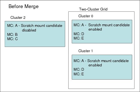
Figure 7-8 Management Class definition before merge

Figure 7-9 MC definition after merge
If categories and constructs are already defined on the merging cluster, verify that the total number of each category and construct that will exist in the grid does not exceed 256. If necessary, delete existing categories or constructs from the joining or merging clusters before the grid upgrade occurs.
Each TS7700 grid supports a maximum of 256 of each of the following categories and constructs:
•Scratch Categories
•Management Classes
•Data Classes
•Storage Classes
•Storage Groups
Logical volume considerations
The TS7700 Virtualization Engine default number of supported logical volumes is 1,000,000. With Release 3.0, you can add support for additional logical volumes in 200,000 volume increments using FC5270, up to a total of 4,000,000 logical volumes. The number of logical volumes supported in a grid is set by the cluster with the smallest number of FC5270 increments installed.
If the current combined number of logical volumes in the clusters to be joined exceeds the maximum number of supported logical volumes, some logical volumes must be moved to another library or deleted to reach the allowed grid capacity. In order to maximize the full number of logical volumes supported on the grid, all clusters must have the same quantity of FC5270s installed. If this is not met, the number of volumes that the grid will support is set by the cluster with the smallest number of FC5270 increments installed.
|
Note: The new (merging) grid must have fewer virtual volumes than the existing (receiving) grid.
|
Microcode and feature code for merge
Before the merge of a cluster or a grid into another grid, the following restrictions apply to the merge process:
•When you merge from one cluster or a grid to another grid, all clusters in the existing grids are automatically merged. The merging cluster must be offline and the cluster to be merged is only online if it has 8.21.x.x code or higher.
•A grid-to-grid merge is only supported at 8.21.x.x code or higher, and both grids must operate at the same microcode level.
•Merges are only supported when all clusters in the resulting grid are at the exact same code level.
•FC4015, Grid enablement, must be installed on all TS7700 clusters that operate in a grid configuration, and all clusters must operate at microcode level 8.7.0.x or higher.
•Both existing clusters and merging clusters must contain enough features to accommodate the total resulting volume count post merge.
•The merging cluster must contain FC5271 if the cluster to be merged has it installed.
•If the merging cluster has FC1035 installed, the client’s infrastructure must support 10 Gb.
Merge steps
Here, we describe the steps to perform the merger of the clusters or grids into a grid:
1. Merge cluster tasks performed by the IBM SSR:
a. Verify the feature code.
b. Configure the grid IP address on both clusters and test.
c. Configure and test Autonomic Ownership Takeover Manager (AOTM), when needed. See Chapter 2, “Architecture, components, and functional characteristics” on page 15 for more information.
2. Make changes to HCD channel definitions.
Define the new channels and the device units’ addresses in HCD. See Chapter 6, “Software implementation” on page 285 for more information about HCD.
3. Make changes to SMS and TCDB.
With the new grid, you need one composite library and up to six distributed libraries. All distributed libraries and cluster IDs must be unique. You must now define the new added distributed library in SMS. Make sure to enter the correct Library-ID delivered by the SSR.
4. Activate the IODF and the SMS definitions and issue an OAM restart (if it was not done after the SMS activation). For more information, see Chapter 6, “Software implementation” on page 285.
5. Vary devices online to all connected hosts. After a cluster is merged to a cluster in an existing grid, all clusters in the existing grid are automatically merged. Now, you are ready to validate the grid.
6. Run test jobs to read and write to volumes from all the clusters. Remember, you must verify all LPARs in the sysplex.
7. Modify copy policies and Retain Copy mode in the Management Class definitions according to your needs. Check all constructs on the MI of both clusters and ensure that they are set correctly for the new configuration. See 2.3.25, “Copy Consistency Point: Copy policy modes in a multicluster grid” on page 70 for more information.
8. Test write and read with all the clusters and validate the copy policies to match the previously defined Copy Consistency Points.
9. If you want part or all of the existing logical volumes to be replicated to the new cluster, this can be done in different ways. IBM has tools, such as PRESTAGE, to support these actions. The logical volumes must be read or referred to retrieve the new management policies that you define. The tools are available at the following URL:
7.4.4 Example of creating a three-cluster grid scenario
This section covers the migration aspects to join an empty stand-alone cluster grid TS7700 in a remote location to an existing two-cluster grid TS7700 Virtualization Engine to form a three-cluster grid.
Ensure that the steps in “Preparation” on page 356 have been considered when planning for a multicluster grid.
The three-cluster grid is built on an existing grid. It extends the configuration to three clusters combined into a single composite library, as shown in Figure 7-10.

Figure 7-10 Creating a three-cluster grid
The following procedures show the required steps for joining a TS7700 Virtualization Engine and a two-cluster grid configuration to form a three-cluster grid configuration. You must first verify the items discussed in the following sections.
In the configuration shown in Figure 7-10, two clusters are in the same campus location or in the same city. The clusters can have one of these Copy Consistency Points specified:
•Synchronous Mode Copy Consistency Point
•Rewind Unload (RUN) Copy Consistency Point
•Deferred Copy Consistency Point
•No Copy Consistency Point
Every cluster in the system requires two network connections to a WAN for site-to-site operations, and the WAN connections between the three clusters in the three-cluster grid must be completed. The grid network on the new cluster must be configured, containing the IP addresses of the three clusters.
|
Note: The hardware join process will be done by the IBM SSR using the latest instructions.
|
The following major tasks are used for the join process:
1. Pre-checks on the joining cluster and existing grid are performed by the IBM SSR.
2. Make changes to the SMS.
With a three-cluster grid, you need one composite library and three distributed libraries. You must now define the third distributed library in SMS. Ensure that you enter the correct Library-ID, which is supplied by the SSR.
3. Make changes to HCD.
Define the new channels and the 256 units in HCD. Define channels and units with OFFLINE=YES, and then vary the channels and units online manually, when and if they are to be used. See Chapter 6, “Software implementation” on page 285 for more information about HCD.
4. Set the missing-interrupt handler (MIH) values.
If you are defining specific address ranges in the IECIOSxx member in SYS1.PARMLIB, ensure that the MIH values for the new devices are set. The correct values are described in 6.2.6, “Set values for the Missing Interrupt Handler” on page 306.
5. Activate the IODF and the SMS definitions and issue an OAM restart (if it was not done after the SMS activation). For more information, see Chapter 6, “Software implementation” on page 285. Cluster 2 is not ready yet, and will go online in a later step.
|
Tip: If the new SCDS is activated before the new library is ready, the host cannot communicate with the new library yet. Expect message CBR3006I to be issued:
CBR3006I Library library-name with Library ID library-ID unknown in I/O configuration.
|
6. The IBM SSR joins Cluster 2 to the existing grid.
7. After a new cluster is joined to a cluster in an existing grid, all clusters in the existing grid are automatically joined. This is enough to make the existing two-cluster grid into a three-cluster grid. Cluster 0 in the example can be operational and available for operation during that time.
8. Now, you are ready to validate the new three-cluster grid:
a. If you have a FICON attachment to remote Cluster 2 available, you can vary Cluster 2 defined FICON channels online, making sure that Cluster 2 can be accessed through the channel paths defined in HCD.
b. Vary logical devices for Cluster 2 online.
c. Vary Cluster 2 online to the hosts.
d. Using the D SMS,LIB(libraryname),DETAIL command, validate that the relationship between the composite and distributed libraries is correct as shown in Example 7-1.
Example 7-1 Display composite library
D SMS,LIB(COMPLIB),DETAIL
F OAM,D,LIB,COMPLIB,L=ST6T10-Z
CBR1110I OAM LIBRARY STATUS: 141
TAPE LIB DEVICE TOT ONL AVL TOTAL EMPTY SCRTCH ON OP
LIBRARY TYP TYPE DRV DRV DRV SLOTS SLOTS VOLS
COMPLIB VCL 3957-V06 768 768 287 0 0 368298 Y Y
----------------------------------------------------------------------
MEDIA SCRATCH SCRATCH SCRATCH
TYPE COUNT THRESHOLD CATEGORY
MEDIA1 170345 0 0001
MEDIA2 197953 0 0002
----------------------------------------------------------------------
DISTRIBUTED LIBRARIES: DISTLIB0 DISTLIB1 DISTLIB2
----------------------------------------------------------------------
LIBRARY ID: C0001
OPERATIONAL STATE: AUTOMATED
ERROR CATEGORY SCRATCH COUNT: 33
CORRUPTED TOKEN VOLUME COUNT: 0
----------------------------------------------------------------------
LIBRARY SUPPORTS IMPORT/EXPORT.
LIBRARY SUPPORTS OUTBOARD POLICY MANAGEMENT.
Also, validate that the relationship between the composite and distributed libraries is correct as shown in Example 7-2.
Example 7-2 Display distributed library
D SMS,LIB(DISTLIB1),DETAIL
F OAM,D,LIB,DISTLIB1,L=ST6T10-Z
CBR1110I OAM LIBRARY STATUS: 062
TAPE LIB DEVICE TOT ONL AVL TOTAL EMPTY SCRTCH ON OP
LIBRARY TYP TYPE DRV DRV DRV SLOTS SLOTS VOLS
DISTLIB1 VDL 3957-V06 0 0 0 1348 819 0 Y Y
----------------------------------------------------------------------
COMPOSITE LIBRARY: COMPLIB
----------------------------------------------------------------------
LIBRARY ID: 10001
OPERATIONAL STATE: AUTOMATED
SCRATCH STACKED VOLUME COUNT: 222
PRIVATE STACKED VOLUME COUNT: 108
----------------------------------------------------------------------
LIBRARY SUPPORTS IMPORT/EXPORT.
LIBRARY SUPPORTS OUTBOARD POLICY MANAGEMENT.
CONVENIENCE I/O STATION INSTALLED.
CONVENIENCE I/O STATION IN OUTPUT MODE.
BULK INPUT/OUTPUT NOT CONFIGURED.
e. Vary the logical devices for Cluster 2 offline again so that they will be ready to test if the original two-cluster grid still works.
9. If you do not have any FICON attachment to the remote site, you can still verify your new Cluster 2 with TS7700 MI and Bulk Volume Information Retrieval (BVIR) jobs.
10. Modify the copy policies defined in the Management Class.
The Copy Consistency Points on all three clusters (Table 7-11) must be modified to support a RUN copy between Cluster 0 and Cluster 1, and also a Deferred copy from Cluster 0 and Cluster 1 to Cluster 2. The values must be updated in the Management Classes using the TS7700 Virtualization Engine MI. Ensure that the definitions will work when logical units are allocated from Cluster 2. See 5.4.3, “Defining grid copy mode control” on page 264 for more information. Table 7-11 describes the settings needed for the scenario shown in Figure 7-10 on page 364.
Table 7-11 Copy Consistency Point on Management Class: Three-cluster grid configuration 1
|
Management Class
|
Cluster 0
|
Cluster 1
|
Cluster 2
|
|
From → To
|
From → To
|
New cluster
|
|
|
TS7700 MC A
|
RR → RRD
|
RR → RRD
|
DDD
|
|
TS7700 MC B
|
RR → RRD
|
RR → RRD
|
DDD
|
11. Check all constructs on the MIs of all clusters and ensure that they are set correctly for the three-cluster grid configuration. You can set up scratch allocation assistance (SAA) as outlined in 5.4.4, “Defining scratch mount candidates” on page 268.
12. Run test jobs writing to and reading from the two original clusters in the two-cluster grid.
13. Vary logical devices for Cluster 0 and Cluster 1 offline to be ready to validate the use of Cluster 2 as though there were a disaster, and set up Copy Consistency Points that support your requirements, such as a Deferred copy mode. You can only run that test if you have the correct FICON connection.
14. Test write and read with Cluster 2 and validate the result (if appropriate).
15. IBM SSR: The join process is done. Return to normal production mode.
16. If you want part or all of the existing logical volumes to have a logical copy on Cluster 2, this can be done in various ways. IBM has tools, such as LI REQ COPYRFSH, to support these actions. The logical volumes must be read or referred to retrieve the new management policies that you define. The tools are available at the following URL:
7.5 Remove cluster from grid
FC4016, Remove Cluster from Grid, delivers instructions for a one-time process to remove/unjoin a cluster (either TS7720 or TS7740) from a grid configuration. It can be used for removing one cluster from a two-cluster to six-cluster domain. Subsequent invocations can be executed in order to remove multiple clusters from the grid configuration. After the removal, a Cluster Cleanup (FC4017) can be performed. FC4017 will be required if the removed cluster is going to be reused. A Cluster Cleanup will return the cluster to a state similar to the state shipped by manufacturing, but with the feature codes still in place. Both feature codes are one-time features.
If you need to preserve the data on the removed cluster, ask your IBM SSR.
7.5.1 Purpose
Use FC4016 for the following tasks.
Data center consolidation
A client is consolidating data centers by collecting the data from remote data centers and using the TS7700 grid to move the data to their centralized data center. In this scenario, the customer will potentially have two clusters at the primary data center for high availability. The third cluster is located at a different data center. To consolidate the data center, it is necessary to copy the data from the third cluster to the existing grid in the primary data centers. The third cluster is joined with the two existing clusters and the data is copied with grid replication. After all of their data has been copied to the primary data center TS7700s, the client can remove the third cluster from the remote data center and clean up the data from it. This TS7700 can now be relocated and the process can be repeated.
TS7720 or TS7740 reuse
A client has a multi-site grid configuration, and the client no longer requires a TS7720 or TS7740 at one site. The client can remove this cluster (after all required data has been copied, removed, or expired) and use this resource in another role. Before the cluster can be used, it needs to be removed from the grid domain and cleaned up.
The client is responsible for determining how to handle the volumes that only have a Copy Consistency Point at the cluster that is being removed (eject them, move them to the scratch category, or activate a Management Class change on a mount/demount to get a copy on another cluster). This needs to be done prior to starting the removal process. A new Bulk Volume Information Retrieval (BVIR) option (Copy Audit) is provided for generating the list of inconsistent volumes to help the client.
The removal of the cluster from the grid is concurrent with client operations on the remaining clusters, except for certain steps. During this time, inserts, ejects, and exports will be inhibited. It is advised that the removal of a cluster from the grid will be executed in off-peak hours.
No data, on cache or tapes, on the removed cluster will be available after the cluster has been removed with the completion of FC4016. The cluster cannot be rejoined with the existing data.
No secure erase or low-level format will be done on the tapes or the cache as part of FC4016 or FC4017.
If you need to preserve data on the cluster that you are removing, ask your IBM SSR.
7.5.2 High-level description of the process
This is the high-level description of the preparation activities that occur on the removal of a cluster from an existing domain:
•You must determine whether there are any volumes that are only available on the cluster to be removed (for example, Management Classes defined to only have a copy on one cluster, or auto removal from TS7720). Well ahead of the removal, the client must be managing getting consistent copies on other clusters in the domain. Reference the BVIR Copy Audit function described in the “IBM Virtualization Engine TS7700 Series Bulk Volume Information Retrieval Function User’s Guide Version 1.5” white paper at the following website:
•If there are volumes that only have a valid copy on the cluster to be removed, you must determine how to handle those volumes by performing one or more of the following tasks:
– Eject the logical volumes (see 9.6, “Managing logical volumes” on page 638).
– Move the volumes to a scratch category.
– Activate a Management Class change on the volume with a mount or demount to get a copy made on another cluster.
•Ensure that there are no volumes in the damaged category. You can use the Repair Logical Volumes menu under the MI panel to repair them.
•Modify Management Classes so that the removed cluster is no longer the target for copies.
•If you have microcode level 8.6.0.x or higher installed and the cluster being removed is part of a cluster family, the cluster must be removed from the family before the removal by using the TS7700 MI.
|
Tip: If at least one remaining cluster in the grid is at code level 8.7.0.134 or higher, it is possible to use one of those clusters to perform the removal of another cluster by using FC4016 even if the grid contains two different code versions. Consult with your IBM SSR for the code version prerequisites for FC4016.
|
|
Note: A copy consistency check will be run at the beginning of the process. Do not skip consistency checks unless it is a disaster recovery (DR) unjoin or you can account for why a volume is inconsistent. Failure to do this can result in data loss.
After a cluster has been removed, you might modify the host configuration to remove the LIBPORT IDs associated with the removed cluster.
|
..................Content has been hidden....................
You can't read the all page of ebook, please click here login for view all page.