
HRSG construction
James R. Hennessey, Nooter/Eriksen, Inc., Fenton, MO, United States
Abstract
In this chapter the reader will be taken through the various methods of heat recovery steam generator (HRSG) construction. HRSG construction varies widely in levels of modularization and order of assembly of the components. We’ll explore what is important, considerations for specific jobsites, and design influences. Every part of the HRSG from the inlet duct to the stack including piping, supports, valves, platforms, and auxiliary systems such as burners, catalysts, and ammonia injection components will be covered.
Keywords
HRSG; engineering; procurement; construction; harp construction; coil module; roof beams; C-frame; O-frame; goalpost; modular; modularization; casing; duct; lifting
13.1 Introduction
In this chapter the reader will be taken through the various methods of heat recovery steam generator (HRSG) construction. HRSG construction varies widely in levels of modularization and order of assembly of the components. We’ll explore what is important, considerations for specific jobsites, and design influences. Every part of the HRSG from the inlet duct to the stack including piping, supports, valves, platforms, and auxiliary systems such as burners, catalysts, and ammonia injection components will be covered.
In an HRSG construction budget, there are several basic terms that are important to understand. Direct labor is a cost category that includes labor activities by frontline craft-people who directly contribute to the completion of the HRSG. These direct labor activities would include, for example, bolting or welding casing structural frames, installing coil modules, welding piping, and installing platform grating. When most contractors compare man-hour estimates for HRSGs they are comparing man-hours for direct labor activities.
Indirect labor includes activities by the frontline craft-people that support direct labor activities, such as setting up welding equipment, bringing materials from lay-down areas, or being a hole-watch (observer who monitors worker safety) for a confined space area. Overhead is a cost category in a construction budget that includes craft supervision, engineering support, and scheduling support. Special equipment, such as cranes, are often placed in their own cost category. Crane costs can be high and involve mobilization and demobilization costs as well as rental costs. The cost of the heavy cranes must be weighed carefully against the level of modularization and is a major part of construction planning.
Normally when a conversation about construction comes up, the first question is, “how many man-hours will it take to erect the unit?” This is a very difficult question to answer, so let’s try to get this out of the way up front. Direct labor totals for constructing HRSGs are very difficult to estimate based on previous work. There are many variables that change from project to project. Union versus nonunion jobsites, wage scale factors, competing work in the area, and availability of skilled and experienced craft are just some of the many factors that can influence productivity. Levels of modularization, nonobvious scope, scope that is not easily represented on an estimate, and the amount of direct assistance provided in the field by the HRSG supplier are factors that can directly affect the number of man-hours required.
Most construction firms rely on ever-increasing detail in their estimates to arrive at the number of man-hours required. They estimate quantities that can be tracked during the project execution, such as linear feet of weld, diameter-inches of piping weld broken out by material type, number of bolted connections and weight of temporary steel to be removed. The higher the resolution in the estimate, the better the chances that the production work will come in on target. Using a job that is 5–10 years old in comparing estimates can be risky. As of 2016, HRSG manufacturers have varied their offerings greatly in the past 5 years. HRSGs may look the same to the untrained eye, but they are actually quite unique in their complexity. The leading HRSG manufacturers have spent a great deal of time since at least 2010 making sure their HRSGs are more erector-friendly, while at the same time they have become larger and contain higher alloys and more difficult details to erect in the field.
Erecting HRSGs is not for the faint of heart, but with good knowledge of the scope being purchased and careful estimation up front, a successful project is certainly possible.
13.2 Levels of modularization
The level of modularization in an HRSG can vary widely. The primary driver of the level of modularization is most often the purchaser. Who is buying the HRSG? Is it a utility or an engineering, procurement, and construction (EPC) firm? An EPC firm is an intermediary between the plant owner and HRSG supplier that will be involved in designing and integrating the plant equipment. Will the EPC firm be engaged in the construction as well as the design and will they be involved in the bid evaluation process, looking at the total cost of the installed HRSG, or just the cost of the HRSG equipment?
Utilities are often constrained by public service commissions, municipal regulations, or other rules or regulatory bodies that promote buying an HRSG based on the best price of the equipment under consideration, which may not consider installation. In addition, many specifications do not address modularization or may contain loose, highly interpretable wording. Thus, HRSG scope in projects purchased by regulated utilities or other end users may not contain all of the features and options that can reduce the amount of labor required to install the unit.
When the HRSG purchaser is involved with the installation of the equipment there will usually be more emphasis on total installed cost. The purchaser may choose to spend more on the unassembled HRSG itself, but with the assumption that it will require fewer man-hours to erect and assemble at the jobsite.
Jobsites can drive different levels of modularization as well. In areas with high labor rates, higher levels of modularization are desirable to offset high construction costs. In underdeveloped countries where labor rates are low, the amount of modularization is relatively unimportant; it may even be advantageous to move work from the shop to the field.
Logistics is a big driver of modularization. Is the jobsite near the coast or on a river, where good waterway access can allow very large components to be shipped in by barge? Or is the jobsite far inland and only served by rail or over-the-road transportation?
Availability of construction equipment is also a driver. Are large cranes available and affordable? Larger cranes to erect larger pieces are not always advantageous. The balance between crane cost, crane mobilization and demobilization costs and the size of the equipment being erected must be considered. Of course this balance is highly dependent on location and will vary around the world (Fig. 13.1).

13.3 Coil bundle modularization
The HRSG heating surface is arranged into coil bundles comprised of rows of finned tubes connected to headers and/or return bends at the top and bottom of each tube as seen in Fig. 13.2. For design purposes these rows of tubes and connecting headers are arranged into coils that serve a specific purpose, such as an evaporator or an economizer. For fabrication purposes these coils are combined (or sometimes split) into larger coil bundles that are as large as transportation or construction limits will allow.

The level of modularization is usually defined by the size of the coil bundles and/or how much adjacent steel is attached in the fabrication shop. Each level of modularization has its advantages and disadvantages and it is to the benefit of the purchaser or erector to understand those for each type.
13.3.1 Harp construction
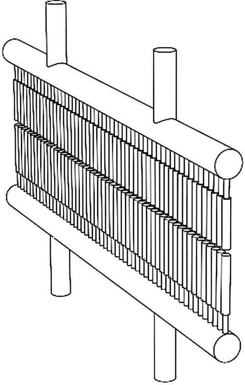
In modern HRSGs the coil bundles are comprised of finned tubes, headers, and/or return bends at the top and bottom of the bundle. Some headers are attached to a single transverse row of tubes and some are attached to two or three transverse rows of tubes as illustrated in Figs. 13.3 and 13.4. A single upper header, single lower header, and the tubes connecting the two is called a harp. When the upper and lower headers are connected by only a single row of tubes this is called a single-row harp. A coil bundle could be made from as few as one harp for a reheater or HP superheater to as many as 20 or more harps for a large economizer or feedwater preheater.

Harp construction is the lowest level of modularization utilized in modern HRSGs. Harp construction would be used in cases where large cranes are not available for erection, or field labor is inexpensive. Harp construction might also be used in areas where there are logistical constraints, such as low-capacity bridges or difficult terrain.
Harp construction requires the most work by the erector in the field. Fig. 13.5 shows an example of the temporary steel used in the installation of harps. The extra labor cost is not normally offset by lower transportation costs as the harps are still long, flexible, and require supporting steel. They take up the same footprint in an ocean freighter as a larger coil bundle. Even by stacking the harps for transport, which requires a substantial amount of support steel, the transport costs for ocean freight are usually no lower than what is typical for higher levels of modularization.

Hence, the harp style of construction is more about limitations than efficiencies. It is utilized more in developing countries than countries with a more developed infrastructure and access to heavy lifting equipment.
13.3.2 Modular or bundle construction
The next level of modularization is combining several harps into a coil bundle or coil module. Coil modules are sized to the clearance or weight limits of the transportation method or the available crane used for lifting. Coil modules are appropriate for inland jobsites where rail transport is used. Stretch trailer trucks and multiple axle trailers can also be used to transport coil modules to the jobsite as seen in Fig. 13.6.

In modular construction the coil bundle is furnished as a multitude of harps assembled into a larger coil. The coils in modern HRSGs are normally top supported for operation and the modular bundle comes to the site with the top support steel attached. This is one advantage of this style of construction. The upper headers are supported in their permanent arrangement and the roof casing is furnished along with the coil bundle. Once the coil module is uprighted and set onto the casing roof beams it is already supported from the top.
In modular style construction, the casing panels are not attached to the coils, with the exception of the roof panel. The casing is built first and completed prior to setting any coil bundles inside of it. In this style of modularization, the casing panels are more modularized than with the goalpost style, which will be described next. Casing panels, including the outer steel casing, insulation and inner liner are attached to the external structural beams. This allows the casing and structural frame to be constructed in fewer pieces than the goalpost style (which we will cover next), but the pieces being transported to the site and erected are usually larger.
With the casing and structural supporting frame being erected before the coil modules are installed, all of the seams that connect the casing panels, called field seams, can be finished with little effort. This is another advantage to the modular style of construction. This advantage is leveraged with the availability of pneumatic man-lifts instead of scaffolding.
Modular construction coil bundles are transported to the jobsite with supporting steel for transportation attached, but this supporting steel is not used for lifting. It is used only for supporting the length of the coil bundle during transportation and facilitating horizontal to horizontal lifting during transit. Such support steel would facilitate offloading the coils from an ocean vessel and placing it on a rail car or transporter for transport to the jobsite. It is not utilized as the main structure in uprighting the coil bundle to the vertical position for insertion into the casing.
For this reason, external lifting devices are needed to upright the modular construction style bundle into the HRSG. This is one disadvantage to the modular style of modularization. External lifting device designs vary and are proprietary to the HRSG supplier. There are two main types of lifting devices. One is a common device that is sized to accommodate different sized coils up to a maximum size. This device is not custom made for each job and is transported from jobsite to jobsite as needed. The second, and least common type, is a custom uprighting device for each coil module. These custom uprighting devices can be designed to contain less steel, but this savings is more than offset by fact that each coil needs its own uprighting device. The coil modules are often shipped inside this device, which also acts as a transport frame.
Using the common-sized uprighting device, as shown in Fig. 13.7, each coil module is placed into the device and tied down. One to three cranes are then used to upright the module depending on the design of the uprighting device. One- and two-crane devices typically pivot off the ground, which eliminates the need for an additional crane that supports the lower end, also called a tailing crane. Three-crane devices do not pivot off the ground and so a separate tailing crane is necessary to support the bottom of the device during uprighting. Three-crane devices offer a slight advantage in that they are relatively fast to load, upright, and set a coil into place. However, the total crane cost can be much higher than for one- and two-crane devices.

Regardless of the method of uprighting, with the modular style design the coils are simply set into place resting on top of the roof beams, already in their top-supported and final configuration. Fig. 13.8 shows a coil module being lowered into position onto its roof beams. This is an advantage over the goalpost style that we will see in the following section.

The modular style coil sets into the casing without any additional support or lifting steel to remove. This is also an advantage of this style of modularization. As will be seen in the goalpost style of modularization, the removal of support and lifting steel can be a substantial amount of work.
13.3.3 Goalpost-style modularization
The goalpost style of construction and level of modularization is often compared to the modular style previously outlined because the casing frame is assembled prior to and separately from the setting of the module boxes. There is a similar amount of work associated with each style for the site erector, but the order of the work and the type of work can differ greatly.
In the goalpost style, the casing frame is erected without any of the casing panels attached to the columns, roof, or floor. The casing frame is erected first with only the floor and sidewall columns, giving the appearance of an American football goalpost. Roof beams are added as the module boxes are set into place. One advantage to goalpost-style construction is that the casing frame can be less expensive to ship since the columns are not attached to the panels in the shop. This does add some additional seal welding and field seam work in the field, however, offsetting some of the transportation savings.
The coil modules, like the modular style, are made up of several harps. The size of the coil is determined by the clearances or weight capacity of the transportation route. Goalpost-style construction is appropriate for inland jobsites where rail or over-the-road transportation is necessary. In goalpost style, the modules also contain a partial box of structural steel around them. This steel serves two purposes. One, it supports the coil bundle so that when it is set into the goalpost frame, it will support itself without buckling. Two, there is sufficient truss steel included to allow the box steel to act as its own uprighting device.
Incorporating the uprighting truss steel into the box is an advantage of the goalpost style. Two cranes are necessary, including a tailing crane to lift the back end off the ground, but there is no need for a separate uprighting device. This simplifies the lifting and setting of the module boxes as compared to the modular style and gives the appearance that the HRSG is being assembled faster than other types of construction.
Once installed, each harp in the coil module box, having been installed as bottom supported, will need to be hung from a roof beam that is added after the module box is set into the frame. The requirement to hang each harp from a new position in the structure is a disadvantage of goalpost-style construction. The time required to perform this work can offset the savings in the ease of uprighting and setting of the module boxes in the frame.
The sidewall, floor, and roof casing are all three attached to the module box in the shop and shipped as part of the module. This can offer an advantage in transportation costs, as mentioned before, as the casing is shipped inside the envelope of the module box. This may decrease the space available for the coil bundle portion of the module box when the steel and casing is included and maximum sizes need to be met to adhere to clearance restrictions. The effect is minimal and does not usually preclude use of this style of modularization.
Because the module box is enclosed in its own steel frame or “box” and includes truss steel for lifting, most of this steel has to be modified or removed once the coil is uprighted, installed, and top supported. Some of the support and lifting steel in the colder ends of the HRSG can be left in place. The lower ends of the module boxes need to be prepped for the downward expansion of the module during operation. In the hotter end of the HRSG, more, if not all, of the steel will need to be removed. Removal of this steel is one disadvantage of goalpost-style construction over the modular style.
13.3.4 C-frame modularization
The next highest level of modularization is commonly called the C-frame. Although the term “C-frame” is broadly used for any level of modularization that appears to be the same, we will define it specifically for our purposes as a coil module with the floor, roof, and sidewall casing including the primary structural frame members that have been attached in the fabrication shop. The term comes from the fact that the floor, sidewall, and roof frame members form the shape of a “C.” Goalpost-style module boxes can have the appearance of a C-frame, but the structural members that surround the module box are not the primary casing frame members. This is the main difference between the two.
C-frame modules are already top supported, meaning that once they are erected in place, there is no need to hang each harp from a newly installed roof beam.
C-frames are generally more expensive to purchase, but the savings in field construction usually offsets the premium paid for the equipment. C-frames have limited applicability as their large size requires that the jobsite be close to a body of water with barge access or that there is a good route with few obstructions to transport the equipment. Fig. 13.9 shows the relatively large size of the C-frame on a transport trailer. C-frame modules can also be heavier than modules of lower modularization levels, so heavier cranes may be required.

Lifting and uprighting C-frames is straightforward. A system of shop-installed truss steel exists inside the “C.” Usually the C-frame is shipped with the sidewall casing in the downward orientation, allowing the truss steel to be placed inside the “C” at the front and rear faces of the coil bundles. Lifting and uprighting requires two cranes, with the second crane being a tailing crane. A pair of C-frames, shown in Fig. 13.10, are usually erected in the same day, allowing for a completed moment frame to be made. A typical arrangement of two modules wide and five modules long can be installed in a week as compared to several weeks for lower levels of modularization.

By virtue of its configuration, the C-frame can be tall when shipped. Many times, C-frame module envelopes can push 22 ft in height or more and when added to the height of a transporter, overhead obstructions such as bridges or power lines can become a problem. When overhead clearances are a problem the C-frame can be rotated 90 degrees so that the sidewall casing ships on the side and the leading and trailing gas flow surfaces on the coil are facing up and down. This sideways C-frame or low-profile C-frame will incorporate modifications to the sidewall casing for lifting reinforcement and there will be steel truss work in what will become the centerline of the HRSG. This centerline truss steel may be removed or remain in place depending on the details provided by the supplier.
13.3.5 O-frame (shop modular) construction
Increasing the level of modularization one step past the C-frame gives you the O-frame or shop modular style of construction. This level of modularization includes the coil bundle, roof panels, floor panels, both sidewall panels, and all structural moment frame beams in a single module as seen in Fig. 13.11. All internal baffling is installed in the shop. Typically, this level of modularization is reserved for single-wide units where the width of the turbine exhaust gas path is at 12 ft or less and is only applicable for gas turbines less than 100 MW in size.

13.3.6 Super modules and offsite erection
When jobsite access is favorable and the local labor situation is difficult or expensive, it may be worth relocating some of the field labor described previously to a less expensive location and shipping very large “super modules” by barge to the site. Super modules are usually fabricated in a ship yard or fabrication facility that has drive-on barge access. Super modules consist of entire sections of the HRSG complete from right sidewall column to left and comprising two or three coil modules deep. The entire heat transfer section of the HRSG could be represented in two to three super modules.
Super modules are built already in the vertical orientation; there is no concern for uprighting. But there is additional steel and structure added for jacking the modules onto a transporter and bracing them for shipment. One super module being transported into its final position inside of a building can be seen in Fig. 13.12.

Many times the drums, piping, and platforms above the HRSG casing roof are added to further modularize the assembly. In Fig. 13.12 it can be seen that the HP drum was included as well as some platform steel, but piping was not installed.
To take the concept one step further, entire HRSGs have been fabricated and erected offsite and transported in one piece to a jobsite. A summary of the different levels of modularization along with their advantages and disadvantages can be found in Table 13.1.

13.4 Structural frame
Regardless of the level of modularization, all HRSG structures are designed as a system of moment frames consisting of sidewall columns, roof beams, and floor beams, as seen in Fig. 13.13. These frames support the coil bundles and the casing that envelops the turbine exhaust gas. The locations in the frame where the frame is completed in the field are called moment frame connections or simply moment connections. For a modular or goalpost level of modularization, there will be four moment connections to be completed in the field. Two are required at each floor beam to sidewall column connection and, likewise, two at each roof beam to sidewall column connection. These connections can be either bolted or welded. The types of connections and design details can be found in Chapter 10, Mechanical Design, but for the purposes of this chapter we will limit the discussion to the method of construction.

Welding is the more traditional approach. In the case of HRSGs located in high seismic areas, welding may well be the best or only option. The thickness of flanges and webs of the moment frames in these jobsites may not lend themselves to a bolted connection.
For jobsites in areas not prone to high seismic loads, bolted moment connections have become the norm in recent years. Bolted connections can differ in their configuration. Web and flange splice plates, where reinforcing plates are effectively bolted across the mating web and flanges, have the disadvantage of containing a high quantity of bolts, but have the advantage of being applicable in higher seismic areas.
An alternative to this is a plate flange design, seen in Fig. 13.14, where plates normal to the axis of the beam are bolted together like flanges on mating pipe. These contain fewer bolts but cannot be used in very high seismic areas.

With any structural connection quality assurance is of the utmost importance. Quality assurance with welded connections includes visual inspection and nondestructive examination (NDE) normally consisting of magnetic particle testing. For bolted connections the quality assurance lies in making sure the bolt or nut is tightened the proper amount. Visual aids such as squirting washers, color changing washers, and twistoff-style bolts can be used to give a visual indication of when the proper tightness is achieved.
13.5 Inlet ducts
The discussion in this chapter so far has been restricted to the coil modules and the casing that surrounds them. While recognized as only contributing roughly 25–30% of the total labor in erecting an HRSG, the method for assembling the casing and coils and the level of modularization are considered by many to be the most important considerations in HRSG erection.
Externally, the inlet duct assembles much like the casing. The duct consists of a frame of columns and roof and floor beams. The casing attached to these columns includes an outer steel layer with reinforcing stiffeners, insulation and a steel liner on the inside. Duct panels can ship from the shop with the columns and beams already attached to them or they can be separate from the steel frame. This may depend on transportation restrictions, but may also depend on the preferences of the HRSG supplier.
At the other end of the scale, the inlet duct could be shipped to the site in shop-assembled boxes with the floors, walls, and roof panels and beams already welded. Transportation restrictions may limit this, but if clearances allow, the purchaser may require more modularization in this area.
Inlet ducts can contain elements that add complexity to the job. Inlet ducts used to be sweeping and gradual transitions from the relatively small exit of the combustion turbine to the much larger face of the first coil. To make the HRSG smaller, less expensive, and to reduce plot space, inlet ducts have become shorter with steeper angles. Working against this dimensional change is the fact that exhaust from combustion turbines has become hotter, with higher velocities and increased turbulence at the exit. These factors can combine to create problems if design and construction details are not given sufficient attention.
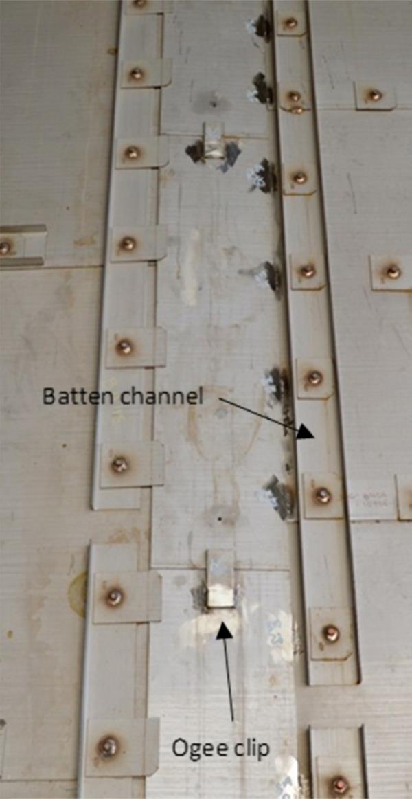
The internal liner system of an HRSG contains multiple overlapping plates that “float” or expand to accommodate the high temperatures of the exhaust gas. Adjacent liners should not be welded together. They should also not be connected so tightly that there will be no opportunity for expansion. Ogee clips are small offset tabs welded on one side but left free on the other to hold down adjacent liners and prevent warping. Ogee clips should be used generously as recommended by the HRSG supplier’s technical field advisor and installation instructions. Square or round washers holding the liner down should be snug and not reveal gaps when walking or pushing on the liner. Most inlet duct systems use channels over the interface of adjacent liners to eliminate warping and for extra reinforcement against turbulence and high exhaust gas velocities. See Fig. 13.15 for an example of these components. The service of the HRSG supplier’s field advisor can be invaluable here as it is easy to overlook the nuances for correctly welding or bolting these components.
On HRSGs with duct burners or catalyst systems where very good flow distribution is required, there will usually be a distribution grid in the inlet duct. The grid is heavy in order to withstand the pressure and turbulence of the exhaust gas velocity. Expansion of the grid is critical to proper operation and, like the inlet duct liner, the nuances are in the details. The grid must be installed in a way that allows proper expansion and not hinder it. There are widely varying levels of shop fabrication in the supports for distribution grids. Care should be taken to fully understand how much field work is required to potentially attach supports or guides that may or may not be installed in the fabrication shop.
Bleed turbulence breakers are accessories occasionally required inside the HRSG’s inlet duct and subject to high exhaust gas velocities. Care should be taken to perform the attachment welds carefully and follow the combustion turbine manufacturer’s design carefully so these devices are able to withstand the loads to which they are subjected.
13.6 Exhaust stacks
Like the other parts of the HRSG, exhaust stack modularization is highly dependent on transportation restrictions. Exhaust stacks involve fairly common methods of shop fabrication and there is usually a wide selection of local or near local fabrication shops capable of manufacturing stack components. This makes transport of larger pieces possible, although not always economical.
The typical size of a knockdown piece of exhaust stack is 180-degree segments × 10 ft tall. Several of these sized segments can fit onto a truck for transportation to the jobsite. In some cases it is advantageous to ask for barrel stave sections in the range of 90- or 120-degree segments by 40 foot long. Although this seam layout may give the erector fewer linear feet of weld, the equipment needed by a fabrication shop to roll or bend 40-foot-long staves is not as common as rolling equipment that can produce 10-foot-long cylinders. Transportation costs may be higher for the barrel stave configuration.
In some cases, it could be possible to fabricate the entire stack offsite and ship it in via heavy haul transporter or barge, but this is not normally the case. In cases where this is possible, stack dampers and stack silencers, if required, should not be part of a shop-assembled package unless they are engineered to be transported as part of the package.
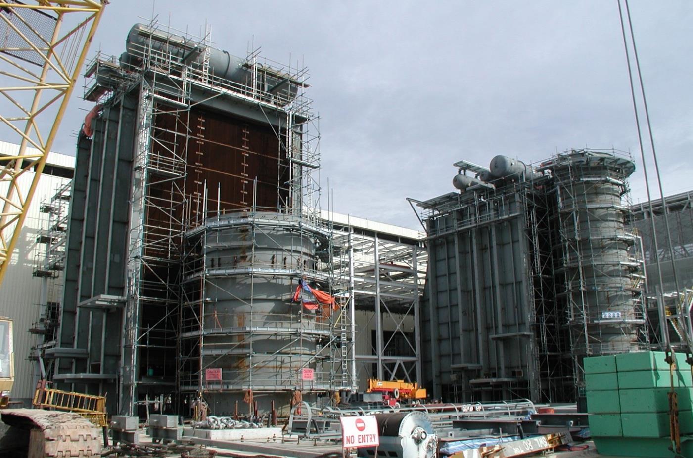
Circumferential and longitudinal seams can be welded from both sides. When welding from both sides the first weld pass or root pass of the first side must be removed after completion of the first side weld to give the welder a clean surface to complete the weld from the back side. This is call back gouging. To eliminate the need for back gouging, backing bars can be added to the shell cans in the shop. Backing bars allow for the entire weld to be made from one side and eliminate the need to remove the root pass. Fig. 13.16 shows an exhaust stack outfitted with scaffolding to facilitate welding of longitudinal and circumferential seams in place.
13.7 Piping systems
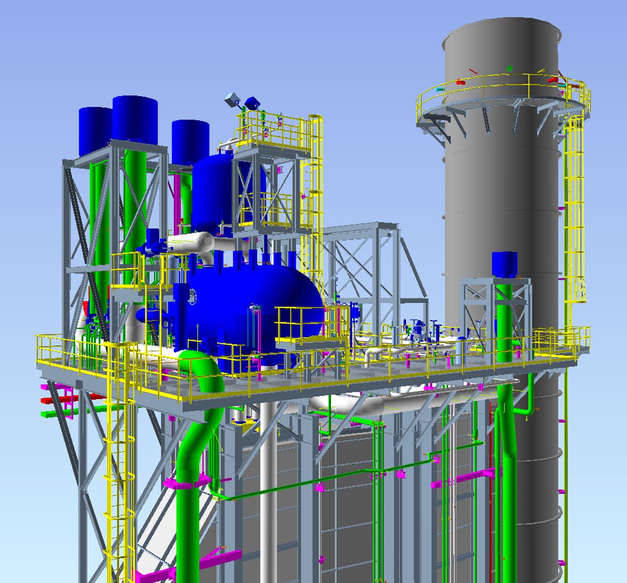
Piping systems can make up the majority of the direct man-hours associated with a project. The complexity of piping systems varies widely and is directly proportional to the number of pressure levels in an HRSG and the temperature of the outlet steam. Fig. 13.17 shows a piping model of a single pressure level HRSG. Modern HRSGs contain a significant amount of 9-percent chrome alloy materials. These alloys require skilled welders, are heat treat sensitive, and require a narrow range on hardness readings for the completed welds. An erector’s quality control system must acknowledge this and monitor these parameters diligently.
With the advent of CAD drawing it is not necessary to add field trim to the ends of each pipe spool as in the past, but certain pipe spools still benefit from some extra tolerance. With evaporator risers it is often helpful to specify some additional length be left on for trimming to accommodate fit-up in the field. An alternate option is to provide short make-up spools for each size pipe in case extra length is needed.
The quantity and size of field welds have an impact on man-hours required. These are the parameters most closely estimated by construction firms. The source of the fabricated pipe can have an impact on number of field welds. Piping fabricated in another country and shipped in containers oftentimes contains more field welds than pipe spools fabricated closer to the jobsite and shipped by truck.
Pipe support systems can be equally complex and vary greatly in details. When possible, the stanchions for pipe supports that weld directly to the pipe should be welded in the shop to eliminate mistakes, and save the time and cost required for heat treating in the field. Again, with CAD drawing of intersecting subsystems (piping, platforms, coils, casing) misalignments are not common and are much easier to correct than to weld the low-alloy supports to the pipe in the field.
Attachment of pipe support systems to piping can be bolted or welded. In many cases, bolted is preferred by the erection contractor, but may take longer to design and fabricate in the shop than is allowed by the contract schedule. This is mostly true where holes need to be drilled into the casing and duct panels, whose purchase order was placed many weeks before piping support systems are completely designed. Requests by purchasers to incorporate more and more bolted connections in lieu of welded connections are pushing HRSG suppliers to be more creative in how they design, draw, and procure equipment.
13.8 Platforms and secondary structures
Secondary structures like the main deck platform, sidewall platforms, silencer towers, access door platforms, and stair towers can have a big effect on man-hours as well. As can be seen from Fig. 13.17, the system of steel that is added to the main casing and coil module structure can be complex. These pieces can be furnished in a number of levels of preassembly. Like piping spools, the location of the source country and shipping method will also have an effect on preassembly levels.
Handrail and toe plate details can affect man-hours and the appearance of the HRSG in general. The level of preassembly should match the purchaser’s expectations, but this is one area where reality can differ greatly from expectations.
Like pipe supports and moment frame connections, the request to have more bolted connections has also affected the design and supply of secondary structures. Incorporation of bolted connections is not as difficult from a scheduling standpoint for platforms as it is for pipe supports. But the desire to have oversized holes to add the benefit of some tolerance will require slip critical connections. Slip critical joints rely on friction to join the two connected pieces instead of relying on shear forces. This can increase the requirements for surface preparation, bolt type, and tightening method.
Vent silencer supports can be shipped in one piece to the jobsite or they can come in many pieces. A stair tower will arrive containing anywhere from 100 to 150 pieces depending on the source. Container shipments of a stair tower from other countries can be in the range of 150 bolted pieces, where truck shipments of a knockdown stair tower can be in the range of 100 bolted pieces. It is necessary to understand how these items are supplied in order to estimate and economically perform the labor required.
There are more highly modularized options for stair towers as transportation limitations are lessened. Stair towers that are supported off the casing are another option to reduce the piece count, but the time in the project to erect this stair tower is not as flexible as it is with a self-standing tower.
13.9 Construction considerations for valves and instrumentation
In the trend to move labor from the field to the shop, HRSG suppliers often offer valves to be welded into the pipe spools in the shop. This has a lot of advantages. Low-alloy chrome piping and valves can more easily be welded and heat treated in a shop. Groups of valves such as drum level control valve stations and economizer drain manifolds can be welded in the shop and economically transported to the jobsite due to the compact nature of the arrangement.
Care needs to be given to timing as some control valves can have very long lead times as well as a long engineering time cycle. This could put certain control valve pipe assemblies onsite much later than a contract allows. Be sure to evaluate the benefits of shop fabrication and honestly appraise how early a particular piece is needed onsite before evaluating options for welding control valves in piping spools.
Small details can make a difference too. It is advantageous to have thermowells in low-alloy chrome piping welded in the shop so that heat treatment will not be required in the field. Provisions for heat treating small seal welds such as these are more expensive in the field than in the shop.
13.10 Auxiliary systems
Auxiliary systems for HRSGs such as duct burners, selective catalytic reduction (SCR), and carbon monoxide (CO) catalyst systems are not difficult to install as long as provisions are made for their inclusion in the initial design. All these systems are furnished in their own duct space. Duct burner runners, which produce the flame, and burner baffles, which help shape the flame by controlling exhaust gas flow, are normally fabricated to a high level of modularization. Part of the duct burner system includes external gas control skids and flame scanner cooling air blower skids. These are completed in a shop and set on a small foundation next to the HRSG. The piping is then run and completed between the skids and burner runners.
Catalyst systems are fairly straightforward. SCR catalyst blocks are large, weighing approximately 1 ton each, and are stacked on top of each other with a crane and fastened to a frame to give support against exhaust gas flow. The SCR system includes an ammonia injection system and lances that inject the ammonia into the exhaust gas flow. The ammonia injection system includes an ammonia vaporizing skid, completed in the shop and set on a foundation next to the HRSG. The ammonia vaporizer is connected through a header to the individual injection lances. These lances are perforated pipes inserted horizontally through the casing and supported in the center of the duct.
CO catalyst comes in much smaller blocks that can be lifted by a person and are stacked by hand from scaffolding.
Important considerations for systems equipment are delivery timing of the catalyst systems and time allowed at the end for commissioning and tuning of the equipment. Catalyst systems should not be delivered too early and subjected to damage and/or contamination at site. They should be delivered just prior to startup or as directed by the catalyst manufacturer.
13.11 Future trends
Combined cycle power plant requirements are changing faster and faster every year. Here are a few trends that are affecting construction details and schedules.
Diminishing quantity of skilled labor in North America is probably the leading driver of change in how HRSGs are designed for ease of erection. Increased modularization to minimize field labor and increased use of bolted connections are two areas that address a shortage of welders.
Changes to the way electric power plants are being developed are putting more pressure on HRSG suppliers to provide shorter and shorter deliveries. Not only does this affect the engineering and procurement cycle for the HRSG supplier, but it affects the construction and commissioning cycle for the erector as well. Once a customer wins an award to provide power into an area, there is tremendous pressure to deliver on time.
Outside the North American market and other parts of the developed world, the trend will be the evaluation of total installed costs as labor costs rise and the cost to erect the HRSG becomes more significant. Methods of modularization pioneered in these areas should spread throughout the world and new innovations will appear.