
Mechanical design
Kevin W. McGill, Nooter/Eriksen Inc., Fenton, MO, United States
Abstract
This chapter provides an understanding of the mechanical and structural components required for the heat recovery steam generator (HRSG). The HRSG is composed of a significant number of integrated mechanical components contained within a structural supporting system. All of the components must consider temperature and pressure influences, with the main structural supporting system being capable of resisting external forces from wind and seismic actions. The design of the components must first establish the appropriate design parameters; the specific designs must follow designated codes of design. The sections in this chapter will summarize the applicable design principles and best design practices.
It is critical that the HRSG must allow for thermal loads to be resolved and focus on eliminating low-cycle fatigue potential issues as well as provide a design for the full design life specified by the owner.
Keywords
Design code; materials; mechanical design; structural design; pressure parts; structural solutions; seismic
10.1 Introduction
The heat recovery steam generator (HRSG) is composed of numerous mechanical heating surface components (superheaters, evaporators and economizers) and steam drums. The heating surface elements are bare and finned tubes integrated with collector headers and interconnecting piping systems. All of the mechanical pressure parts systems are constructed with structural details and supports. The entire HRSG is contained within a gas-tight steel casing system with a main structural system to support all of the components and is anchored at the concrete foundation.
As such, there is a significant engineering effort to perform all of the mechanical and structural designs required. Thorough design approaches for these components are necessary to provide reliable solutions and a final delivered and quality constructed product that maintains its design integrity during the expected operational design life of the HRSG.
For the purposes of this chapter, engineering references will be utilized from the American Society of Mechanical Engineers (ASME), American Society of Civil Engineering (ASCE), and American Institute of Steel Construction (AISC). It is understood and acknowledged that there are many different permissible codes of design around the world, including local codes establishing alternate or additional requirements for delivering an acceptable and approved engineering design.
The primary design code utilized for mechanical components, i.e., pressure parts, is ASME Section 1: Rules for Construction of Power Boilers.
The primary design code utilized for structural components is ASCE Minimum Design Loads for Buildings and Other Structures. This code’s purpose is for establishing the design parameters (design loads and analysis approach) for the structure.
Additionally, the AISC Steel Design Manual is used for the specific design of steel elements.
10.2 Code of design: mechanical
The requirements and design approaches specified by ASME Section 1 are intended to produce a safe boiler design. The code’s intent is to consider the necessary components for safety and then provide detailed engineering rules governing the design and construction of the various components of the HRSG.
For an HRSG, code rules are specified for [1]:
It is important to note that this chapter will emphasize the mechanical design of the HRSG. It is also critical that the following proper efforts are carried out to deliver a reliable and quality product [1]:
10.3 Code of design: structural
Similar to any mechanical codes, the basis for building code development is to safeguard the health, safety, and welfare of the public. The primary goal of building codes is the protection of human life from structural collapse. The goal is not to focus on minimizing damage to the structure.
The codes will provide minimum load requirements for the design of the structures. Loads and load combinations are developed for the appropriate design approach. The foundation of the code includes [2]:
• basic requirements (stiffness and serviceability)
• general structural integrity (design load combinations and load path)
For the specific design of steel elements, the code species [3]:
10.4 Owner’s specifications and regulatory Body/organizational review
The owner or engineering, procurement, and construction (EPC) contractor will specify to the HRSG manufacturer their specifications. In addition to the design codes applicable and the minimum code requirements permitted, the specifications will define the maximum operating envelope, along with the expected level of operation over the life of the HRSG. The owner is responsible for defining all applicable loads and conditions acting on the HRSG that affect its design.
Depending upon the requirements for permitting and acceptance of the HRSG, various regulatory bodies or formal approval processes are required by law or local jurisdiction. There can be significant differences between the requirements to be supplied and approved, but the main concept is to assure quality in all aspects of the delivery, installation, and operation of the HRSG.
10.5 Pressure parts
10.5.1 Design methods
ASME Section 1 is an experience-based design methodology and it is referred to as design by rule. Design by rule is a process requiring the determination of loads, the choice of design formula, and the determination of an appropriate design stress for the material or detail to be utilized [1,4].
The basic requirements and rules for pressure vessels are designated for typical mechanical component shapes under pressure loadings within specified limits. The design rules do not cover all geometries, loading, and details. Guidance may be provided for the evaluation of other loadings. When design rules are not presented, the manufacturer is responsible for determining the stress analysis necessary to validate the design provided.
Design by analysis may be used to establish the thickness and specific configurations and details in the absence of design by rules for any geometry of loading conditions on the element.
10.5.2 Design parameters
The owner is responsible for providing the operating envelope for all scenarios so the design parameters can be determined and established by the manufacturer. The design parameters for the HRSG are established by determining the maximum design envelope with any additional margin provided based upon appropriate engineering judgment and experience or designated by the owner’s specifications.
Design codes generally do not dictate or specify the criteria for establishing the design pressure (P) and design temperature (T) for the boiler components and are the responsibility of the manufacturer.
Design pressure is the pressure used in the design of a vessel component together with the coinciding design temperature (metal temperature) for the purpose of determining the acceptable thickness and inherent details of the component.
Design temperature for any component shall not be less than the mean metal temperature expected coincidentally with the corresponding maximum pressure. If needed, the mean metal temperature can be determined by analysis using accepted heat transfer methodologies [1].
10.5.3 Material selection
Based upon the design pressure and design temperature for the component, the appropriate material is selected. The material selection must be a code permitted material, but can be chosen to deliver the best economical/value design. Availability and fabrication processes can factor in determining the best available material for the intended component.
Material selection is fundamental to the design of the HRSG components. The codes are developed to take great care in ensuring safety and quality. Each code permitted material will have a comprehensive defined specification that will summarize the requirements for [5]:
• ordering, the manufacturing process
• chemical composition requirements
• nonmandatory requirements such as stress relief, nondestructive examination, and additional testing
The customer may designate additional requirements, based upon experience of specific materials to ensure the consistency and quality required in the design.
10.5.4 Mechanical component geometries and arrangements
The main mechanical (pressure parts) components for the HRSG are:
1. Tubes
Finned tube geometries are defined by tube material, tube diameter, tube thickness, fin material, fin height, fin thickness, and fin density (Fig. 10.1). Tubes are finned by electric fusion welding (bonding). The heating surface layout is typically a triangular (or “staggered”) pitch between tubes, although rectangular (or “inline”) pitch is also used.
Other critical pressure parts components include:
2. Headers
Headers are primarily used for the collection of tubes within a coil bundle:
a. Upper headers are also used to support the finned tube arrangements. Furthermore, they provide the points where piping connects different coil bundles and the steam drum.
b. Lower headers are also used for the collection of drainage. They also provide the points where piping connects different coil bundles and the steam drum.
Header-to-tube connection types for openings can be set-on, stick-through, or reinforced connection construction depending upon the required design approach or details specified. See Fig. 10.2 for the applicable arrangements and details.
3. Piping
Piping provides the means for distributing water, saturated steam, or superheated steam to the integrated coil bundles, steam drums, inlet from the water source, and outlet to the steam turbine.
4. Steam drums
Steam drums are water reservoirs containing saturated steam/water separators located above the evaporator coil bundle. They are usually connected to the evaporator coil bundle by external piping systems.
Note that all of the main mechanical components are cylindrical vessels under internal pressure at an associated temperature.


10.6 Mechanical design
10.6.1 General information
The next sections will describe the basic fundamental design concepts required in the code.
10.6.2 Internal “Hoop” stress
The basic formula for determining wall thickness (t) for cylindrical components under internal pressure (tube, pipe, headers, and drums) is [1]:
10.6.3 Reinforced openings (compensation)
Design equations are specified for the evaluation of openings in vessel components and are based on a system of compensation in which the material removed for the opening is replaced as reinforcement in the region immediately around the opening.
Openings can exist in shells, headers, and heads of components and are defined as either single openings or multiple (pattern) openings. Types of connections include piping nozzles, manways, and inspection openings for maintenance and repairs. Code requirements provide design rules and guidance for the shape and size of the opening, as well as limits of reinforcement of the shell to reinforce the connection (Fig. 10.3).

The general requirements for adequate reinforcement of the opening is given by [1]:
Depending upon the reinforcement required in the shell, different nozzle details can be implemented. A self-reinforced nozzle is typical for thicker shells and when there is little remaining thickness in the shell (for “hoop” stress) to reinforce the opening (Fig. 10.4).

In the case of multiple openings, the appropriate ligament (distance between adjacent openings) reduction factor must be considered in the calculation of the shell thickness for the impact of overlapping compensation between openings. The controlling ligament reduction is based upon the heating surface layout and the hole pattern in the header. All of the following must be evaluated (Fig. 10.5):

The ligament reduction factor is determined by specific calculations of each surface direction indicated. The variables include tube pitch (circumferential and longitudinal) and hole diameter.
10.6.4 Allowable design stress
The following behaviors are the basis for establishing the foundation of the allowable stress for the design of the HRSG components.
1. Elastic/plastic behavior
Elastic behavior for steel elements is represented by the region from 0 to A in Fig. 10.6 and is reversible. As the forces are removed from the element, the element returns to its original shape. Linear elastic deformation is governed by Hooke’s law, which states [6]:
where
σ=applied stress
Ε=elastic modulus![]() =strain
=strain
This relationship behavior only applies in the elastic range. The slope of the stress/strain can be used to determine the elastic modulus of the steel.
Plastic behavior for steel elements is irreversible. Any steel element experiencing plastic deformation will have initially undergone elastic deformation. Steels generally have large plastic deformation ranges due to the ductile nature of the material.
Under tensile stress, plastic deformation is characterized by a strain hardening region and then a necking region and finally with fracture/rupture. During strain hardening, the material becomes stronger so that the load required to extend the specimen increases with further straining. The necking phase and region is indicated by a reduction in cross-sectional area of the specimen. Necking begins after ultimate strength is reached. During necking, the material can no longer withstand the maximum stress and the strain in the specimen rapidly increases. Plastic deformation ends with the fracture of the material.
It is to be noted that steel materials are assumed to maintain continuous, homogeneous, and isotropic behaviors.
2. Yield strength
Yield strength of the material is the stress when the material stops deforming elastically and starts to deform plastically. It is the stress at which a material exhibits a specified permanent deformation or elastic limit. This fractional amount of deformation will be permanent and is nonreversible [6].
3. Ultimate tensile strength
Ultimate tensile strength is the capacity of the material to withstand loads developing tension and is measured by the maximum stress that a material can withstand while being stressed/pulled before failure. The ultimate tensile strength of a material is determined by the maximum load of the element at rupture/failure divided by the original cross-section area of the material tested. Tensile strength is an important measure of a material’s ability to perform in an application, and the measurement is widely used when describing the properties of metals and alloys [6].
4. Creep strength
Creep is the behavior of a solid material that deforms permanently under the influence of mechanical stresses and can occur as a result of long-term exposure to high levels of stress. Creep is more severe in materials that are subjected to high temperatures for long periods of time. The stress levels developed are still below the yield strength of the material.
The rate of creep deformation is dependent upon the material properties, exposure time, exposure temperature, and the applied structural load. Depending on the magnitude of the applied stress and its duration, the creep deformation may become large enough that a component can no longer perform its function or may even ultimately fail.
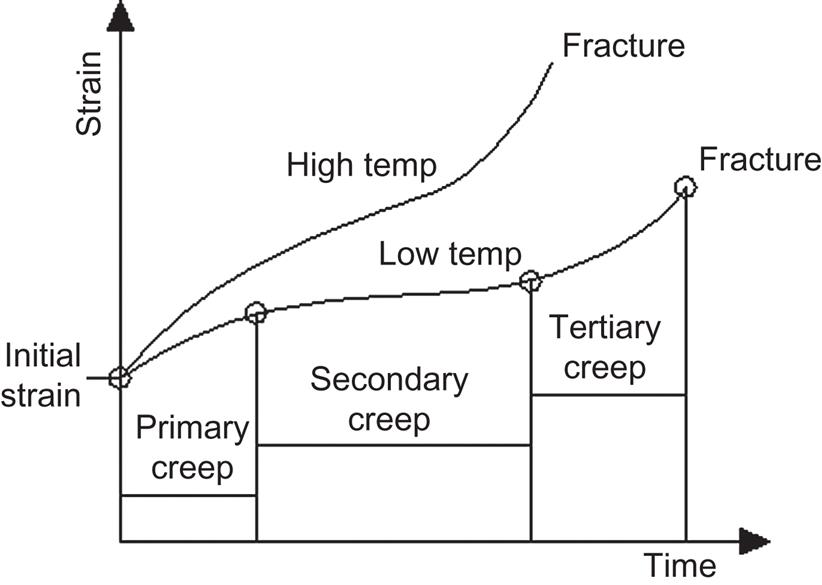
Unlike brittle fracture, creep deformation does not occur suddenly upon the application of stress. Instead, strain accumulates as a result of long-term stress and is therefore a time-dependent deformation (Fig. 10.7).
The stages of creep are:
• Primary creep is the initial stage of creep, where the strain rate is relatively high, but ultimately slows with increasing time due to strain hardening.
• Secondary creep is the stage where the strain rate eventually reaches a minimum and then becomes relatively constant as a result of the balance between work hardening and annealing (thermal softening) of the material. Stress dependence of this rate depends on the creep mechanism.
• Tertiary creep is the final stage of creep, where the strain rate exponentially increases with stress because of necking behavior of the material. Fracture will occur during the tertiary stage of creep.

Creep is a very important critical aspect of the material and dictates how the materials are selected for the hottest components of the HRSG, i.e., superheaters/reheaters.
It is important to note that in the ASME code the allowable stress values for creep established are based upon 100,000 hours of operation. It is typical for HRSGs to be expected to be designed for 250,000 hours to 300,000 hours, so other means must be established to consider the design life requirements of the contract properly.
The established allowable stress value for design is then determined by the limits defined divided by a factor of safety specified in the code of design. In the case of the ASME code, the allowable stress value of the following will be the minimum of [7]:
• yield strength at design temperature/(1.5)
Note:The values of 1.5 and 3.5 are established by the ASME code as factors of safety for design.
All material specifications will designate maximums for temperature and provide all of the necessary requirements for the material to be designed accordingly and deliver for the design life intended. Other design codes may establish different factors of safety but may also in conjunction require different testing and inspection minimums of the material.
10.7 Pressure parts design flexibility
10.7.1 General information
Changes in the market require HRSGs to operate less in base load mode and more in peaking mode with frequent start-ups and shutdowns. This higher level of cyclical operation impacts the HRSG, and it has been necessary to consider a multitude of new design concepts and specific details for a reliable HRSG.
The engineering design process will help identify any critical detail requirements or operational limits that will impact the reliability of the components and design details for the expected design life of the HRSG. Many of these code design rules are established for the basic purpose of ensuring a safe design but do not ensure reliable operation or even flexible operation for an intended design life because the primary design rules are often based on operation at base load (steady load), rather than cyclical service.
After the HRSG’s basic design has been performed in accordance with the specified design code and owner’s specifications, it is also then necessary for the manufacturer to specify a specific set of design rules to be used for detailed design of the components whose life may be impacted. Many of the design codes provide guidance useful in the detailed design of some life impacted components, but may not provide useful guidance or are absent for others.
To provide a quality HRSG, the manufacturer must take the responsibility of performing all applicable analysis to validate the design. Some key elements in the HRSG for delivering the final design include [8]:
Without proper consideration of the above factors and a proper design analysis performed, premature pressure part damage and failures that are attributed to thermal mechanical fatigue can occur. Many of these, known as low-cycle fatigue (LCF) failures, are common in HRSGs.
10.7.2 Coil flexibility
Before cycling of combined-cycle plants became typical, it was not necessary to make HRSG coil bundles flexible in designated places to eliminate or at least minimize low-cycle thermal fatigue. Low-cycle fatigue was limited to when expansion was restricted. With the current operational envelopes, it is now essential to provide this flexibility for maximizing HRSG longevity. Low-cycle fatigue is almost always due to unresolved thermal expansion and resulting stresses. Non-corrosion-related failures of HRSG tubes, pipes, and headers are typically caused by low-cycle thermal fatigue. There are two important aspects of coil flexibility to consider: tube-to-tube temperature differentials and superheater/reheater interconnecting piping.
1. Temperature differentials
In all high-temperature superheaters/reheaters, differences in tube metal temperatures develop as steam is heated from inlet to outlet. In most HRSGs, the rows of tubes closest to the gas turbine will be the hottest and those nearest the stack the coldest. Tubes at different temperatures expand at different rates. These differences in temperatures and expansion rates are greatest at startup and lessen as full steam flow is established.
There are two commonly used options for configuring coils to deal with row-to-row temperature differences:
a. Fig. 10.8 (four-row superheater coil with spring support) depicts one of them. Here, steam enters the inlet header and is heated by the exhaust gas. In the configuration shown, the inlet header at the top of Row #4 is fixed to provide support while the lower headers are allowed to move vertically unrestrained. All row-to-row temperature differentials must be absorbed within the coil by header rotation, tube flexing, and/or axial compression or tension of the tubes. Under transient conditions (such as during unit startup and shutdown), the mechanical stresses developed by the temperature differentials are at the highest and are sufficient to produce thermal fatigue. As a result, any HRSG whose mechanical support configuration restrains both upper headers from moving vertically would develop damage each time it is cycled. To minimize the impact, the addition of a spring-type support to either header would enable the tube row to which it is attached to move vertically, decreasing thermally induced stresses by an order of magnitude.
b. Fig. 10.8 (four-row superheater with fixed headers) illustrates an alternative superheater/reheater coil configuration option that has commonly been seen in the industry. Here, each tube row is supported from above by its own fixed header, and link pipes connect the lower headers to a collector manifold. In this configuration, the maximum thermal stresses are at the bends in the link pipes. This layout does not lend itself well to cycled HRSG operation because components cannot move freely relative to each other. Absorption of row-to-row temperature differentials depends entirely on the flexibility of the coils and the link pipes and rotation of the manifold.
Note the coil bundle implementing the spring-type support at the outlet header allows the header to move up or down depending on the temperature difference between the rows. The spring-type support will both facilitate free relative tube movement and allow for maximizing row-to-row flexibility.
For contrast, the coil bundle configuration not implementing the spring-type support will only be able to withstand a minimum row-to-row differential in the magnitude or rate of thermal expansion. Specifically, the tube rows cannot move freely relative to each other because they are tied together, either by upper and lower headers or a manifold. It is worth noting that while these types of layouts work well in evaporators (where row-to-row temperature differentials are much smaller), these layouts leave superheater/reheater tubes vulnerable to cycling-induced thermal fatigue.
Interconnecting piping. During HRSG startup, it is common for the piping not heated by gas flow that interconnects superheaters/reheaters to be hundreds of degrees (°F) cooler than the coil bundles to which it is attached. During normal operation (after startup), the temperature differential between the piping and coils is much smaller and might be accommodated by the piping’s flexibility. Regardless, it is important that the layout of interconnecting piping consider the temperature differences that occur during startup. Fig. 10.9 shows a configuration that connects the top of the superheater/reheater coil on the right to the bottom of the coil on the left. Similar arrangements are used for HRSG components such as evaporators and economizers, but these components exhibit fewer thermal-transient problems due to the large amount of water they contain, helping to keep them at a more constant temperature. During startup, the tube rows closest to the gas turbine will heat up faster than the rows further from it. It is a necessity for the interconnecting piping to be designed with sufficient flexibility to handle the force created by these differential thermal expansions.
2. Component thickness
Most owner/operators of combined-cycle plants require the HRSG to reach thermal equilibrium quickly enough to minimize the startup time of the plant. Assuming that all potential low-cycle fatigue problems have been addressed properly, the next criticalities in this area are the fatigue damage caused either by pressure gradients or by “through-thickness” thermal gradients. Of these two gradients, the latter is of greater concern. The magnitude of these thermal gradients is a function of component thickness, where the thinner the component will result in a lesser thermal gradient and the resulting stress. It is good design practice to make HRSG parts, such as superheater/reheater headers and the high-pressure steam drum, as thin as possible to maximize the HRSG’s heat up rate. Design approaches include:
a. Keeping high-temperature headers as thin as possible by using a single-row harp construction, with multiple inlet and outlet nozzle branch connections (Fig. 10.8). Because there is only one tube row per header, the header’s diameter is smaller and its resulting thickness can be minimized. Unfortunately, such a configuration requires many inlet and outlet nozzles to handle the steam flow and creates a more complex layout for the external piping to the steam drum.
b. Utilizing tube stubs that are thick enough to partially reinforce the hole (Fig. 10.10). This design detail can reduce the header thickness significantly. For steam service coil bundles operating in the creep range during thermal transients, a thicker tube stub also helps to further minimize the temperature difference between the tube and the header by conducting more heat. The use of stubbed headers also makes it easier to perform nondestructive examination of the welded joint for a higher-quality fabrication.
c. Use of stronger materials, such as T9l/P9 l chromium steel or even applicable stainless steel materials, which have good fatigue and creep characteristics to minimize the thickness of high-temperature HRSG components such as HP superheaters/reheaters. The outlet headers and steam piping of superheater/reheater sections should use SS347H stainless steel materials for very high temperature applications.


10.7.3 Material transitions (dissimilar metals)
An HRSG utilizes a number of different materials and resulting metallurgical properties due to the full range of design conditions existing for the boiler. These different materials must be joined at specific locations to reflect the changes in temperature and even stresses in the system. This is highly important in elevated temperature regions, where creep is a factor in the service life of the component. The designer must carefully consider where dissimilar welds should be placed in the system, as well as the appropriate weld filler material to ensure limiting the impacts of the dissimilar metallurgical properties.
One main design approach is to implement dissimilar metal transitions at circumferential joints only and avoid perpendicular joints. An example of where a material transition can be implemented in a circumferential connection with the proper weld filler material is Grade 22 to Grade 91 tube or pipe with a Grade 91 filler material (Fig. 10.11).

Perpendicular joints of dissimilar metals to avoid are tube-to-header connections and piping manifolds with pipe branches. In these cases, the headers should be fitted with a tube stub or pipe branch with the same material as the header moving the material transition to a circumferential joint where the stronger weld filler material can be used. These transitions are acceptable using the stronger weld filler metals because the coefficients of expansion are at a magnitude where the stresses developed is controlled.
Stricter rules must be used in a type of transition such as from Grade 91 to TP347H due to the greater difference in the coefficients of expansion. In this specific case, it is recommended to use a material transition, such as an Inconel material that splits the difference in the material differential expansions. The transition component must be constructed with a proper length to both transition the stress and be a reasonable length for handling for the fabrication of the component. Due to the criticality of this material transition, it should be located in an accessible area for regular monitoring/maintenance, and therefore located in the piping system versus within the applicable coil bundle.
10.7.4 Others
There are other areas of focus that can significantly assist with delivering a more reliable HRSG for the expected design life. These include:
1. Preventing quenching
The superheater/reheater sections of the HRSGs are susceptible to desuperheater problems. It is critical that any water introduction by improper equipment operations, overspraying, or leakage be detected and removed quickly. Should this happen, the damage from quenching that results is usually severe and damage may occur within a single cycle.
For an HRSG, the issue of desuperheater spraying or leaking and entering the hottest coil bundles can be managed with the implementation of drain pot components, both upstream and downstream of the desuperheater, located in the steam piping system. The drain pots are constructed with conductivity probes that detect any water entering them. When the water level reaches an unsafe height, a corresponding valve automatically opens, evacuating water.
2. Condensate management
Current and future HRSGs will generally be cycled daily. It is typical practice to keep the HRSG warm and at pressure to minimize thermal gradients and pressure stresses during startup. Condensate that has not been removed from the HRSG superheaters/reheaters could create large tube-to-tube temperature differentials and resulting severe thermal stresses.
Additionally, the HRSG is purged prior to igniting the gas turbine to ensure all fuel gas has been vented. The resulting exhaust gas will be below saturation temperature of steam in the various sections during the purge cycle resulting in large amounts of condensate forming in the superheaters/reheaters.
Proper drain layouts and sizing are also critical to ensure condensate is removed properly from the HRSG.
3. Feedwater recirculation
During a hot or warm startup of an HRSG, it is typical for the preheater to be shocked with cold inlet water. After a shutdown cycle and while the HRSG is bottled up (closed to the outside air), the temperature of the lower pressure sections will rise to match that of other sections. At startup, there is normally no demand for feedwater because the water in the steam drums is swelling.
During these periods, the HRSG components containing feedwater can be steaming or at saturation temperature. A feedwater recirculation system routes water through the feedwater heater prior to startup. As the HRSG demands water, the cooler feedwater can be introduced gradually and mixed with the hotter water already in the feedwater heater. This eliminates or minimizes temperature shocking.
Other system arrangements minimizing any potential thermal shocking can be considered.
4. Auxiliary equipment
As previously indicated, it is typical to maintain HRSGs that are cycled daily at both pressure and temperature between each startup and shutdown of the boiler.
Main components to assist with this are:
Use of a stack damper is the most effective way to prevent cool air from flowing through the HRSG. Supplementing the damper by insulating the stack and the stack breeching up to the damper will enable the heat and pressure to be retained for a meaningful length of time.
Another supplemental means is to implement is a steam sparging system to introduce steam into the lower sections of the evaporator coils. Steam sparging is most effective at preventing the HRSGs from freezing.
10.8 Structural components
10.8.1 Dead loads
Dead loads are gravity loads of constant magnitude and are located at fixed positions that act permanently on the structure. These loads consist of the weights of the structural system itself and all other material and equipment contained in and attached to the structural system.
Dead loads consist of all materials of construction incorporated into the HRSG, including heating surface components, casing and structural system, steam drums, all associated piping and support systems, platforming access systems, instrumentation, and insulation.
The weight of the structure is not known prior to the actual design and aspects are typically assumed based upon past experience. After the structure has been analyzed and the member sizes determined, the actual weight is calculated by using the actual member sizes and the weights of the components to validate any assumptions.
10.8.2 Live loads
Live loads are loads of varying magnitudes and positions and are produced by the use and occupancy of the HRSG. Live loads include any temporary or transient forces that act on a structure or structural element. The acceptable live load will vary based upon the occupancy and classification of the structure or structural element, but will be defined in the customer specifications and the specified building code for each project. It is typical to have both an area live load and concentrated live load requirements. Thermal forces caused by thermal expansions and vibrational loads developed should be considered as live loads.
The position of a live load may change, so each member of the structure must be designed for the position of the load that causes the maximum stress in that member. Different members of the structure may reach their maximum stress levels at different positions of the given load.
10.8.3 Wind loads
Wind loads are produced from the flow of wind around a structure. The magnitude of wind loads that may act on a structure is dependent upon the geographical location of the structure, obstructions in its surrounding terrain, and the geometry and the vibrational characteristics of the structure itself. The determination of wind loads is based on the relationship between the wind speed (V) and the dynamic pressure (q) induced on a flat surface normal to the wind flow.
This can be obtained by Bernoulli’s principle [2]:
Wind loads are site-specific driven and should be included in the owner’s specification requirements. This should include the code of design and the main design parameters. Local codes may also impact the design parameters.
The steps for determining the main wind force-resisting system are [2]:
1. Determine risk category of structure.
2. Determine the basic wind speed (V); the values are based upon a nominal design 3-second gust wind in miles per hour at 33 ft aboveground for exposure C based upon occupancy category.
3. Determine the wind load parameters:
a. Wind directionality factor (Kd), exposure category (based upon surface roughness from natural topography), topographic factor (Kzt) (wind speed-up effects at abrupt changes in the general topography), gust effect factor (G), enclosure classification, internal pressure coefficient (GCpi), and velocity pressure exposure coefficient (Kz)
4. Determine velocity pressure (qz).
10.8.4 Seismic loads
The foundation of the structure moves with the ground during a seismic event and the aboveground portion of the structure resists the motion due to the inertia of its mass causing the structure to vibrate in the horizontal direction. These vibrations produce horizontal shear forces in the structure.
In order to design a structure to withstand an earthquake, the forces on the structure must be determined and specified. The seismic forces in a structure depend on a number of factors, including the size and other characteristics of the earthquake, the distance from the seismic fault, the site geology, the type of lateral-load-resisting system, and even the importance of the structure. All of these factors should be included in the owner’s specifications, including any references to specific local codes requirements.
The design code–defined forces are generally lower than those that would occur in an earthquake, even a large-sized earthquake. This is the case because the structure is designed to carry the specified loads within allowable code stresses and any deflection limitations. The allowable stresses for design are less than either the ultimate or even yield capacities of the materials within the structure. It is philosophically assumed that any larger loads that may actually occur will be accounted for by the factors of safety and by any redundancy and ductility of the structure [9].
The determination of the design seismic load for the HRSG is dictated by these controlling variables [2]:
1. seismic ground motion values
a. mapped acceleration parameters, site class, site coefficient, and risk-targeted maximum considered earthquake spectral response acceleration parameters, design spectral acceleration parameters
The base shear is dependent upon the estimated mass, stiffness of the structure, period of vibration, damping of the structure, as well as the characteristics of the soil. The magnitude of the base shear depends upon the amount of seismic energy that the structure is expected to dissipate by inelastic displacement.
The structural system designated is dependent upon the level of ductility that the system is expected to provide. The seismic force-resisting system is designed to resist the induced forces and dissipate the energy causing the acceleration of the structure.
1. Analysis procedures
The two primary analyses utilized are [2]:
With an equivalent static force procedure, the inertial forces are specified as static forces using empirical, codified formulas. The formulas do not explicitly account for the dynamic characteristics of the structure being designed. However, the formulas were developed to represent the dynamic behavior of regular-type structures, which generally have uniform distribution of mass and stiffness.
Structures that do not fit into this category are termed irregular structures. Common irregularities include large variations in mass or center of gravity and soft stories (openings or noncontinuous elements). These types of structures violate the assumptions on which the empirical formulas are based and this may lead to wrong or insufficient results. In these cases, a dynamic analysis should be used to specify and distribute the seismic design forces. A dynamic analysis should account for the irregularities of the structure by modeling the specific dynamic characteristics of the structure. This would include the natural frequencies, mode shapes, and damping.
The equivalent lateral force analysis is permitted for all structures except those with any structural irregularities. The HRSG structural arrangement meets this criterion.
The modal analysis is permitted for all structures.
Both of these analysis approaches utilize four primary seismic parameters [2]:
The equivalent lateral force method applies a set of equivalent forces on each level of the structure that produces horizontal deflections that approximate the deflections caused by the ground motion. A total horizontal force (seismic base shear) is calculated and is distributed vertically to each story. A linear elastic analysis is then performed to determine the seismic force effects in the structural components (Fig. 10.12).

The seismic design category and the lateral system type are utilized to establish a minimum level of inelastic/ductile performance that is required in a structure. The corresponding expected structure performance is codified in the form of an R-factor, which is a reduction factor applied to the lateral force. The intent is to balance the level of ductility in a structural system with the required strength of the system.
The response modification coefficient (R) represents the ratio of forces that would develop in the seismic load-resisting system under the specified ground motion if the structure possessed a pure linearly elastic response to the applied forces.
Fig. 10.13 shows the relationship between (R) and the design-level forces, along with the corresponding lateral deformation of the structural system.

Factors that determine the magnitude of the response modification factor are the predicted performance of the structure subjected to strong ground motion, the vulnerability of gravity load-resisting system to a failure of elements in the structure, the level of reliability of the inelasticity the system can attain, and the potential backup frame resistance such as that which can be provided by dual frame systems. As illustrated in Fig. 10.13 and in order for a structure to utilize higher R-factors, the lateral system must have multiple yielding elements, and the other elements of the structure must have adequate strength and deformation capacity to remain stable at the maximum lateral deflection levels. A lower value of (R) should be incorporated into the design and detailing of the structure if the structure redundancy and element overstrength cannot be achieved.
2. Overstrength factors
All seismic load-resisting systems fundamentally rely on dissipation of earthquake energy through some varying level of inelastic/ductile behavior. To maintain this behavior, an overstrength factor (Ωo) is applied and the specific components that must be designed to remain elastic are designed with the amplification force [2].
3. Redundancy
Redundancy is ensured when a number of structural hinges form throughout the structure in a successive manner and when the resistance of the structure is not dependent upon a single element to provide the full resistance of a seismic event. To consider a proper minimum level of redundancy in the structure, the reliability factor (p) is used. When a structure has redundancy, this factor amplifies the lateral forces used in the design of the lateral system [2].
The HRSG structure is typically designed with a high level of redundancy due to the nature of the supporting system. The number of frames with full penetration moment connections provide considerable means of redundancy in the event of a member or joint failure to allow load distribution to adjacent structural elements.
Summary impact. It is important to note that the relative size and weight of the HRSG is significant (substantial) with an overall general profile of 150 ft. long to 40 ft. wide to 100 ft. tall. This results in the HRSG main frame elements typically being controlled by the seismic design requirements of the project, including even when the seismic requirements are low in comparison to high wind load requirements. This then produces the importance of a proper design approach for selecting the appropriate steel material grade and overall shape profiles, including any specific welding details, and finally the necessary frame moment connections details in order for the actual fabricated components to behave as the analysis has considered. All of this is integrated into producing a reliable, safe, and most economical design for the system.
10.8.5 Operating and other loads
There are several types of other loads that must be considered. Operating loads include the weight of the components’ liquid contents and any impacts of movement loads from thermal expansions, unbalanced pressure loads, and erection loads. Other loads can be self-straining forces and impact loads from machines and equipment integrated within the HRSG, such as cranes and hoists. Snow loads can be of impact based upon the site location.
10.9 Structural solutions
10.9.1 Design philosophy
The lateral and longitudinal force-resisting system is comprised of a series of steel moment-resisting frames, roof and floor diaphragms, and side wall shear panels. The HRSG is designed as a three-dimensional system comprised of these components. The load combinations for design are designated by the specific code required and are calculated and applied to the system in proportion to their mass. Each frame is designed using the latest AISC LRFD (load and resistance factor design) strength design method (other analyses can be considered). The frame moment connections at the column to roof and floor beams are designed for the appropriate overstrength capacity as specified by the code. The baseplates and shear blocks transfer lateral forces to the foundation slide plates. The HRSG is typically made of two basic structural systems, one to resist lateral forces and one to resist longitudinal forces (Fig. 10.14)

10.9.2 Lateral force-resisting system
In the lateral direction, the equipment is restrained by a series of steel moment-resisting frames. These frame systems are tied together at both the HRSG roof and floor by steel plate casing panels. The rigid panels act as diaphragms distributing the lateral forces to adjacent frames, and provide a redundant lateral resisting system. Each column, roof, and floor beam is braced against buckling in the weak axis direction by welding the member directly to these rigid panels at the inside flange. The outer flange is braced on maximum 15 ft. intervals by casing stiffeners, which provide both rotational and weak axis directional restraint.
At the foundation, the moment-resisting frames are considered pinned on the lateral fixed side and as a roller on the opposite side of the HRSG to account for thermal displacements (average casing temperature of 140°F). At the foundation, one side is designated as the lateral fixed side. The other column baseplates are allowed to expand in the direction away from the lateral fixed side. The cross-section of a typical moment-resisting frame can be seen in Fig. 10.15.

The distance between the frames is determined by shipping constraints and maximum weight considerations. Casing panels for the sides, roof, and floor are made of columns, beams, plates, and stiffeners and are shipped to the jobsite in sections as large as possible.
10.9.3 Longitudinal force-resisting system
In the longitudinal direction, the seismic forces are resisted by large vertical stiffened steel plate shear walls. These external stiffened panels are designed to contain the slight internal pressure inside the equipment created during operation. The combination of vertical shear walls and columns provides for the rigid element that resists the longitudinal earthquake forces and transfer loads to the foundation. At the foundation, one or two column lines (depending upon maximum shear forces developed) are designated as fixed column lines. The other column baseplates are allowed to expand in the direction away from the fixed column line. The shear forces are gathered at the base of the shear panel by using lateral force collectors, also known as drag struts (elements that transfer lateral forces from one vertical element to another). These loads are then transferred to the fixed columns through a longitudinal restraint and finally to the foundation.
Fig. 10.16 provides an illustration for the directional displacement of the HRSG system at the foundation, dependent upon the designated lateral and longitudinal fixed point locations.

The boiler components are placed inside this structural box system. For boiler performance reasons, the gap between the boiler components and the sidewall casing is kept to an absolute minimum. As the boiler components heat up during operation, any gap at the sidewalls is taken up by thermal expansion. As a result, the entire boiler system of casing and boiler components is considered to act together. No interaction between the casing and boiler components is considered to be significant in the lateral direction but rather the boiler components will move along with the stiffened moment-resisting frame system. In the longitudinal direction, the boiler component inertia forces are transferred to the external system through the roof and floor panels to the side shear walls in membrane action.
10.9.4 Anchorage (embedments)
The HRSG is supported at the foundation at each column baseplate. One side of the HRSG is considered as the lateral fixed side and one column line (frame) is designated as the longitudinal fixed line. The HRSG is permitted to expand in both the lateral and longitudinal directions away from the fixed lines (points). The expansion is controlled through the use of shear restraints attached to the concrete embedments.
The shear load path for the column to the foundation is a direct load path (load profile #1 in Fig. 10.17).
1. shear load in the column is transferred to the baseplate through the column to baseplate welds,
2. from the baseplate to the shear blocks that are welded to the slide plates,
3. from the slide plates to the foundation through a shear key-type detail welded to the bottom side of the slide plate.

The uplift load path for the column axial load is through the baseplate for compression and through the anchor bolts for tension. Anchor bolts should not be designed for resistance to shear loads.
Some installations can consider baseplates as all pinned locations. In these cases, the thermal expansion of the HRSG during operation must be considered as additional forces in the structural frame system. Different arrangements and variables can determine which anchorage solution is the most desirable.
10.9.5 Material selection
Due to project economics, material availability, project schedule and other direct issues, it is often necessary to consider materials other than only American Society for Testing and Materials (ASTM) materials for the main structural frame members. Alternate materials from other standards, such as Japanese Industrial Standard (JIS), Chinese Standard (GB), or European Norm (EN) may be utilized.
In most instances, these materials have limited shapes and the HRSG frames must then be constructed with built-up beam assemblies from plate fabrication. In all cases, the grade of steel is roughly 50 ksi and ranges from different material grades based upon the plate thickness of the element. In these cases, it is also possible and sometimes advantageous to consider different shape geometries to ultimately minimize the overall weight of the frame elements. This type of approach is permissible and even preferred, as long as all of the proper code design checks are validated.
10.10 Piping and support solutions
Piping and pipe supports are a large part of the design scope for the HRSG. Piping connects all of the components within each pressure level from the economizers to the evaporators, from the evaporator to the steam drum, and the steam drum to the superheaters. External piping comes from the inlet water source to the economizer and goes from the superheater outlets to the steam turbine. Due to the nature of all of the integrated components, the general piping layouts can be congested in order to fit in all of the scope into the space available. As a result, flexibility in the piping and integration of the supports within the HRSG external structure is critical. There can be a tremendous difference in the complexity of support solutions with less-than-desirable pipe routings that will result in additional design time, fabrication, and erection of the components adding costs and time for field construction. The code of design is typically ASME B31.1 Power Piping. It is the general requirement that piping consisting of a temperature greater than 300°F is analyzed. Piping flexibility analysis must consider the most severe operating temperature condition sustained during startup, normal operation, shutdown, and/or any potential upset conditions. The analysis must also consider all external forces, such as wind and seismic loadings. The design methodology for allowing flexibility and expansion to minimize thermally induced loads while restraining the piping sufficiently for wind and seismic loadings is a balance that requires experience and good engineering judgment.
Establishing meaningful boundary conditions (how the restraints and end points are modeled) directly impacts the validity of the results. The appropriate load transfer and restraint reactions with the correct types of forces/moments and magnitudes to best represent the actual behavior of the system in operation are essential for proper piping designs.
The steam piping is the most critical piping for the HRSG. From the steam drum outlet through the final superheater/reheater, the temperature can increase from 650 to 1100°F. As a result, the flexibility and supporting system must be carefully considered. The operating range for these components will be more severe than just the designated design pressure and temperature. All components, especially the alloy components, are impacted significantly by the severity of startup and/or shutdown and how they introduce temperature differentials to the coil bundles and piping systems. The analysis must evaluate the operating range where maximum stresses will occur. In most of these arrangements, spring-type supports for the wider operating range are required to support the piping properly and maintain stress levels under the code limits.
Typical piping material for steam piping is alloy steel SA335-P11 (1¼ Cr), P22 (2¼ Cr), or P91 (9Cr) grade.
The water piping will have more inherent flexibility due to the smaller diameters typically utilized and due to the layout and space available for providing proper flexibility. The piping stress analysis and supporting solutions will permit utilization of more standard supports and supporting configurations.
Typical piping material for water piping is carbon steel SA106B or C-grade.
The designation pipe support refers to all assemblies such as hangers, anchors, guides, sway braces, restraints, and any supplementary steel required to attached to the pipe support that is integrated into the HRSG steel. Pipe supports can be either welded or bolted to the piping.
10.11 Field erection and constructability
Due to the nature of market demands and the cost restrictions, schedule, and availability of skilled workers for completing site erection, a wide range of design options and features are required from HRSG manufacturers. Projects often require shop fabrication to the greatest extent possible to minimize field work. In many instances, this has driven design solutions to bolted-type solutions arrangements rather than those requiring extensive field welding. This applies to both the main HRSG frames and many casing details. This also includes solutions such as bolted platforms, bolted pipe supports, and shop-fabricated welded valve and pipe assemblies. These types of solutions require great flexibility in executing the overall mechanical and structural design of the project, where a much higher integration of design efforts and coordination with fabrication is required. Each owner or EPC may evaluate different needs or simply may evaluate offerings from the HRSG manufacturer differently. This requires an overall better understanding of how each offering provides the best value of the final supplied and installed components. This trend of different offerings or overall innovation in the design and final details will continue.
10.12 Fabrication
Fabrication is not specifically defined in ASME Section I. Fabrication is related to all of those activities by which the manufacturer converts material (plate, tube, pipe, etc.) into completed boiler components. These activities include [4]:
The design codes generally permit the manufacturer a broad range in fabrication due to the wide range of variation in manufacturing practices. These areas are generally covered in the requirements of the owner’s specifications. Design codes will specify requirements for critical fabrication areas, such as specific welding requirements, and are to be used in conjunction with the general design requirements of the code. These requirements can include [3,4]:
While not covered in this chapter, the fabrication, quality control, transportation (shipping) of equipment, and reliable construction details are all needed to ensure the overall quality and ultimately the reliability of the HRSG.
10.13 Conclusion
For an HRSG, there are a significant number of individual mechanical and structural components integrated into the overall HRSG. The design process is very involved, considering mechanical elements with an operating temperature range of 300–1200°F and pressure range from 150 psig to 3000 psig. This requires proper material selection and detailed consideration of thermal impacts to allow for flexibility and freedom of movement and rotation of the components.
All of the mechanical elements must be supported and restrained accordingly. The overall structural support system must be designed for the combined impacts of potential high seismic and/or wind loadings based upon the specific site location.
Each of the sections presented contains only the basic considerations required for the overall mechanical and structural design, as an entire book or series of books on the design requirements and best design practices could be established.
As gas turbines continue to evolve to larger machines with higher operating temperatures and pressures, and with HRSGs targeted for additional cyclic service, the design challenges will continue to increase.