
Introduction
Vernon L. Eriksen, Nooter/Eriksen, Inc., Fenton, MO, United States
Abstract
Combined cycle and cogeneration power plants have been popular for a number of years due to their high efficiency, low emissions, and a number of other reasons. Due to its ability to start up quickly and respond to demand changes rapidly, the combined cycle power plant’s popularity has increased even more in recent years, to complement variable energy sources such as wind energy and solar energy.
The role of the heat recovery steam generator (HRSG) in combined cycle and cogeneration power plants is discussed in this chapter. Characteristics of HRSGs are presented and types of HRSGs are listed.
Finally, the focus and structure of the book are outlined.
Keywords
Heat recovery steam generator; steam turbine; gas turbine; combined cycle; heat recovery boiler; firetube heat recovery boiler; watertube heat recovery boilers; cogeneration; natural circulation; forced circulation; assisted circulation; once through design; Benson design
1.1 Gas turbine–based power plants
A number of different power plants use the gas turbine engine as their primary driver. Among them are the simple cycle, the combined cycle, many (but not all) cogeneration facilities, and the recuperative cycle to name a few. Heat recovery steam generators (HRSGs) are used in combined cycle plants and in cogeneration plants that utilize the gas turbine as their primary driver, so the expression gas turbine–based power plants will be used to refer to these two types of plants for the purposes of this book. Furthermore, there is very little difference between the HRSG used in a combined cycle plant and the HRSG used in a cogeneration facility, so one often finds the expressions used interchangeably in the industry. We will try to distinguish between the two when necessary in this book.
1.1.1 Advantages
Combined cycle power plants and cogeneration power plants that use the gas turbine engine as their primary driver have been popular for a number of years for a number of reasons.
Efficiencies of over 60% based on lower heating of the fuel have been achieved by these facilities. Other fossil fuel power plants, such as plants with conventional boilers, have efficiency in the range 40–42% for supercritical technology and 45–47% for ultrasupercritical technology based on lower heating value of the fuel.
Gaseous emissions from gas turbine–based power plants are very low. Oxidizing catalysts can be used to convert carbon monoxide to carbon dioxide, and NOx reduction catalysts that utilize ammonia can be used to convert oxides of nitrogen to nitrogen and water vapor and reduce these two types of emissions to 2 ppm. Due to their high efficiency and the fact that they usually burn natural gas fuel, gas turbine–based power plants also emit far less carbon dioxide than other types of fossil fuel power plants.
Capital cost is lower than other power plants.
Reasonably priced natural gas (primarily due to the development of shale gas) is available at least in the US market.
They have a small footprint and do not require much space when compared to other modes of power generation.
A small operating and maintenance staff is all that is required.
It is relatively easy to permit them.
Construction time is short compared to other types of power plants.
Lastly, due to its ability to start up quickly and respond to demand changes rapidly, the combined cycle power plant has become the ideal companion for renewable power generation sources such as wind energy and solar energy, whose output is variable.
1.1.2 History
Although recent markets for combined cycle power plants have been strong and there has been rapid development of the technology since the mid-1990s, the basic technology has existed for a considerable length of time. References to systems being installed as early as the late 1940s exist in the literature. Development continued into the 1960s, when systems up to 35 MW in size were being built. The 1970s brought about demand for larger amounts of power, especially for intermediate load (run primarily during the workday), and turbine manufacturers responded with larger gas turbines and larger combined cycle plants. General Electric referred to their combined cycle plants as STAG (steam and gas) while Westinghouse called theirs PACE (Power at Combined Efficiency). Plants of this era utilizing a single gas turbine could be as large as approximately 100 MW. Both the STAG and PACE plants utilized vertical gas flow, horizontal tube, forced circulation HRSGs manufactured by both General Electric and Westinghouse at this time.
The oil embargo of the 1970s slowed the market in the United States; however, a brisk market in Saudi Arabia developed. Both General Electric and Westinghouse stopped manufacturing HRSGs at this time; however, their partners in Europe and Asia continued.
Federal legislation (i.e., the Public Utility Regulatory Policies Act or PURPA) in the United States stimulated a market in the late 1970s and early 1980s for cycles that only needed to export a small amount of energy to qualify for tax incentives. This legislation led to the formation of independent power producers (IPPs), who developed projects to take advantage of the situation. Opportunities increased and an entire industry developed. HRSGs at this time were designed to work with standard gas turbines and meet the various export energy requirements of each individual application. Due to wide range of steam flows and conditions encountered along with the operational flexibility required by the different sites, the vertical tube, natural circulation HRSG became the technology of choice.
In the late 1990s and early 2000s an extremely large market developed in the United States and a significant market developed in many other areas for shorter periods of time for both IPPs and conventional utilities. Development of larger and more efficient gas turbines continued at an escalating pace and HRSG development continued in parallel. The very large and efficient HRSGs that we see today are a result of this development. Fig. 1.1 shows a photograph of a modern combined cycle facility. Refs. [1–3] were used in the preparation of this section.

1.1.3 Outlook
Looking forward, a strong market for gas turbine–based power generation systems should continue due to the high efficiency and low emissions achieved by these systems along with their ability to support intermittent energy sources such as wind and solar energy. An abundance of reasonably priced natural gas in many areas will only increase opportunities for them.
Most projections available show growth in power generation from natural gas. The US Energy Information Administration projects growth of 40% in power generated from natural gas between 2013 and 2040 for their reference case with the natural gas share of the power generation market growing from 27% to 31% over that period of time.
1.2 Heat recovery steam generator (HRSG)
The HRSG is a special boiler within the broader category heat recovery boilers. The expression heat recovery boiler covers a wide range of boilers and boiler systems that recover energy from a variety of different heat sources. The gas flows from these sources vary widely in flow rate, pressure, temperature, composition, and cleanliness of the gas. Most heat recovery boilers, other than the HRSG, utilize one, or two at the most, levels of steam pressure. The gas flow in a heat recovery boiler can be either on the inside or outside of the tubes. When the gas flow is inside of the tubes, the heat recovery boiler is referred to as a firetube heat recovery boiler. When the gas flow is outside of the tubes, the heat recovery boiler is referred to as a watertube heat recovery boiler. Firetube heat recovery boilers have been used in the process industries for many years and have proven to be especially useful when the gas being cooled is pressurized. They are often referred to as waste heat boilers for these pressurized applications. HRSGs, which are watertube heat recovery boilers located behind gas turbine engines, have become the largest category, both in number of units produced and in physical size, in the general category of heat recovery boilers. HRSGs have many things in common with conventional boilers; for example, they contain evaporators, economizers, and superheaters. They also use round tubes, headers, and drums and need to be designed to boiler codes. They also have many differences; they rarely contain a water-cooled combustion chamber, they usually use smaller diameter tubes than a conventional boiler, and they make extensive use of finned tubing. Many of the differences that HRSGs have from conventional boilers are features that they share with air-cooled heat exchangers. The HRSG is thus a cross between a conventional boiler and an air-cooled heat exchanger.
1.2.1 Role of the HRSG in the power plant
Although the gas turbine engine is the heart of the combined cycle or gas turbine–based cogeneration power plant, a well-designed HRSG is critical for a successful application. The gas turbine is usually a somewhat standard product that comes in a number of fixed sizes. Its output is dependent on ambient conditions. Steam turbines also tend to come in fixed sizes. The HRSG, on the other hand, can be custom designed using relatively standard features. This ability for custom design of the HRSG provides the opportunity to mix and match a number of standard gas turbines and steam turbines to fit a variety of applications. It is worth noting that a well-designed HRSG does not know or care if it is functioning in a combined cycle or cogeneration application. It is merely responding to input from the gas turbine to generate steam at the conditions required by the application.
HRSGs perform several other functions to support not only the gas turbine but also the entire power plant. When the exhaust gas from the gas turbine does not contain enough energy to meet the needs of the power plant, a burner can be included within the HRSG to increase its output. The burner provides very efficient utilization of the fuel consumed. If the emissions from the gas turbine do not meet project requirements, a carbon monoxide catalyst can be included to reduce carbon monoxide levels and a selective catalytic reduction catalyst can be included to reduce levels of nitrogen oxides. The finned tubing utilized in HRSGs provides substantial reduction of noise levels present in the gas turbine exhaust and additional silencing can be included within the HRSG to reduce noise levels even further.
1.2.2 Characteristics
The basic HRSG is generally considered to be the device that starts at the exhaust of the gas turbine and ends at the exit of a stack that releases exhaust gas to the atmosphere. The HRSG contains in its most basic form ductwork and casing (enclosure), economizers that heat water to near saturation, evaporators and steam drums that convert water from the economizers to steam and separate the steam from water, superheaters and reheaters that heat steam beyond saturation, and a stack that exhausts to the atmosphere. A substantial amount of piping, valves, controls and platforms and stairways are necessary to complete the HRSG. Fig. 1.2 contains a photograph of a typical large HRSG.

HRSGs vary widely in size since they are used behind gas turbines that range in size from a few MW to over 400 MW. Small HRSGs can be highly modularized with only a few components that ship on trucks or rail cars and are easily assembled in the field. The largest HRSGs are approximately 140 ft long, 80 ft wide, and 130 ft tall (excluding the stack, which can be much taller). A large HRSG could include 28 large modules of tubes, 3 or 4 steam drums, and over 100 truckloads of ductwork, casing, piping, and miscellaneous steel. Many tube bundles, each of which requires a rail car for shipment, weigh as much as 250 tons and total weight of the HRSG can be 7000 tons. Total heating surface in one of these large HRSGs can be 7,000,000 ft2. Whereas assembly of a small, modularized HRSG is quite straightforward, installation of a large, complex HRSG is a major field construction project.
1.2.3 Types of HRSGs
There are a number of different types of HRSGs to meet the varying needs of different applications and satisfy the varying preferences of different customers. HRSG technology has also evolved over the years and new concepts have been introduced.
Before reviewing the different types of HRSGs, it is useful to discuss the concept of boiler circulation. Most HRSGs and industrial boilers and a substantial number of conventional utility boilers contain a steam drum and have a circulating mixture of steam and water in their evaporators. Water from the economizer enters the steam drum and mixes with saturated water. The water mixture from the steam drum then flows through downcomer circuitry to the inlets of the evaporator tubes. This water is heated in the evaporator tubes to form a water/steam mixture that then flows to the steam drum where the water and steam are separated. Dry steam exits the steam drum and is replaced by the water entering the drum from the economizer. Circulating boilers offer several distinct advantages. First, the presence of a water/steam mixture in the evaporator tubes provides strong cooling of the tubes and prevents the buildup of scale and dryout of the tubes. Secondly, the use of a circulating boiler and steam drum permits the use of continuous blowdown to maintain the level of solids in the water at a level where scale will not form on the inside of the evaporator tubes. Since the solids present in the feedwater will not evaporate, they remain in solution in the drum water and do not leave the drum with the dry steam. Continuous blowdown, which is a discharge of a small amount of water from the steam drum, controls the accumulation of solids. Circulation in a circulating boiler can be maintained either by taking advantage of the natural buoyant forces present in the steam/water mixture or through the use of pumps. Water flows through the economizer to the steam drum in a circulating type of boiler due to the pressure developed in the boiler feedwater pumps that deliver feedwater to the boiler system. As it absorbs heat and generates steam, the evaporator establishes steam pressure adequate to force steam through the superheater. The pressure at the superheater outlet is established by the equipment receiving the steam.
The most common types of HRSG are listed below and will be described in greater detail throughout the book.
1.2.3.1 Horizontal gas flow, vertical tube, natural circulation design
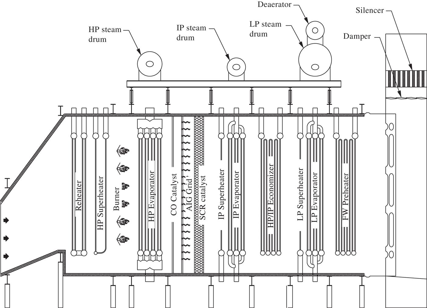
The horizontal gas flow, vertical tube, natural circulation HRSG shown schematically in Fig. 1.3 is by far the most common design utilized in today’s market. Gas enters the HRSG on the left, flows across the vertical tubes where steam is generated, and then flows up the stack. This design uses the natural buoyant forces of the steam/water mixture in the vertical evaporator tubes to circulate the mixture and satisfies virtually any application up to 3000 psi steam pressure. It requires a minimum amount of control and is easy to operate, flexible, responsive, and reliable. Since it has a steam drum, conventional boiler water treatment can be used.
1.2.3.2 Vertical gas flow, horizontal tube, forced circulation design
The vertical gas flow, horizontal tube, forced circulation HRSG shown schematically on Fig. 1.4 was used in the early days of combined cycle development and was very common in Europe, Japan, and the Middle East into the 1990s. Gas enters from the left, turns upward, and flows over the horizontal tubes, where steam is generated. This design requires pumps to circulate the water/steam mixture through the tubes to the steam drum. Conventional water treatment can be used.

1.2.3.3 Vertical gas flow, horizontal tube, natural circulation design
The vertical gas flow, horizontal tube, natural circulation HRSG shown schematically in Fig. 1.5 evolved from the vertical gas flow, horizontal tube, forced circulation unit described above. The primary driver in development of this design was the desire to eliminate circulating pumps and the power consumption and maintenance associated with them. The two designs look similar. The main difference is the location of the steam drums. Conventional water treatment can be used.

1.2.3.4 Small once-through design
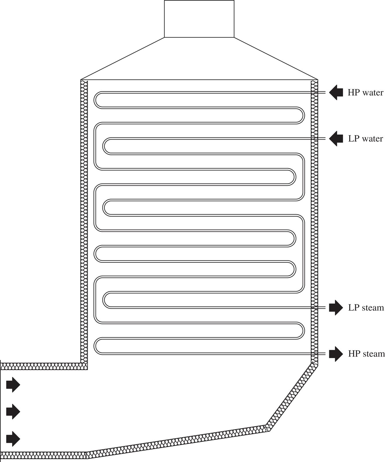
The small, once-through HRSG can have either vertical gas flow as shown schematically in Fig. 1.6 or horizontal gas flow. Tubes are usually horizontal. This design differs from the natural circulation and forced circulation designs described above in that the evaporator does not have a circulating water/steam mixture in it: the inlet of the evaporator contains 100% water, and the outlet contains 100% steam. It is preferred to have a limited number of continuous water/steam flow paths that extend from the economizer inlet to the superheater outlet to minimize flow maldistribution. A steam drum is not required; however, feedwater quality must be exceptional as any solid material in the boiler feedwater cannot be removed by blowdown. It will either deposit on the evaporator tubes or flow from the HRSG into equipment downstream. The most common unit of this type in the market is highly modularized and uses high-alloy tubes, whereas most HRSGs use carbon steel tubes in their economizers and evaporators and low-chrome alloy tubes in their superheaters and reheaters.
1.2.3.5 Large once-through design
A large once-through HRSG would look very similar to the small unit shown in Fig. 1.7. It would not be as modularized due to its size and would not necessarily require high-alloy tubes. Exceptional feedwater would again be required. Large once-through HRSGs utilizing this technology are still in the development phase.

Once-through designs are attractive primarily due to the fact that they can operate at steam pressures approaching and even exceeding the critical point as they do not require a density difference between water and steam to circulate. Feedwater quality must match the purity requirements of the steam entering the steam turbine.
1.2.3.6 Benson design
The Benson HRSG is a once-through design that utilizes horizontal gas flow and vertical tubes as shown schematically in Fig. 1.8. The hot end of the evaporator is designed to utilize buoyancy in the hottest tubes to increase flow of the water/steam mixture to them. The continuous water/steam flow path mentioned in Section 1.2.3.4 is interrupted midway through the evaporator in order to accommodate this feature. Exceptional feedwater is again required as it is for other once-through designs. A limited number of plants utilizing this technology have been built in recent years.

1.2.3.7 Enhanced oil recovery design
Enhanced oil recovery (EOR) involves the injection of a steam/water mixture into an oil well to heat the oil, reduce its viscosity, and improve recovery of the oil from the well. Water available at these locations is usually of very poor quality containing high levels of dissolved solids. Since treatment of this water would be very expensive, steam of approximately 80% quality is generated in the HRSG and then injected into the ground. The water present in the wet steam carries the dissolved solids through the HRSG and into the well, preventing the buildup of scale on the inside of the tubes.
A once-through design is normally used for these applications. Both vertical and horizontal tubes have been used in these units in the past; however, most recent applications have been of the horizontal tube design. A typical horizontal gas flow horizontal tube unit is shown schematically in Fig. 1.9.

1.2.3.8 Very high fired design
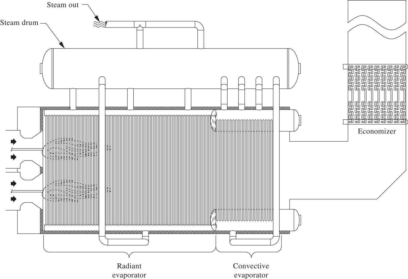
When more steam is required than the exhaust gas from the gas turbine can supply, burners are included within the HRSG to increase its output. The temperature leaving the burner is usually limited to approximately 1600°F in order to avoid damage to the interior walls of the HRSG. Occasionally, far more output is required and, in these instances, water-cooled walls are provided around the combustion chamber and the first few rows of tubes. As for conventional HRSGs with a burner, combustion is very efficient as the combustion air is preheated. In fact, many of these applications resemble a conventional boiler that is utilizing a small gas turbine as a combined forced draft fan and air preheater. These units are very specialized and unique. One style of unit is shown schematically in Fig. 1.10.
1.3 Focus and structure of book
The previous section shows that there are numerous HRSG technologies available for use. The goal of this book is to provide detailed information related to the fundamentals, design, and operation of the prevalent and most relevant technologies in use. Therefore, a short market analysis was performed to determine which technologies are being purchased and to prioritize them. The basis for this analysis was a series of reports published by the McCoy organization (Refs. [4–6] for the years 2013–15. A number of professionals who are active in the power industry were polled to determine the HRSG technology that was used on these projects listed in the McCoy reports. Eighty percent of the HRSGs purchased were known. Horizontal gas flow, vertical tube, natural circulation technology was used for 85% of the known HRSGs accounting for 84% of the plant output. A similar analysis, performed by Scapini (Ref. [7]), of 498 units awarded in the period 2007–09 determined that horizontal gas flow technology captured 85% of the market. Since horizontal gas flow, vertical tube, natural circulation technology is the dominant technology in the market, this book will focus on this technology.
The technologies described in Section 1.2 have many things in common. Much of the information included herein will apply to some or all of them. A fundamental understanding of the material included in this book will be very useful when dealing with the other technologies. Additionally, Chapter 17, Other/Unique Heat Recovery Steam Generators, will focus on the similarities and differences between the prevalent other technologies and horizontal gas flow, vertical tube, natural circulation technology.
HRSGs have some things in common with conventional boilers and other heat exchangers and many things that are unique to themselves. The focus of this book will be on items that are unique to HRSGs as the other items are covered in many other sources.
Lastly, it is not the intent of this book to teach someone how to design a HRSG. The thermodynamics and heat transfer involved could fill a book. The detailed mechanical design could easily fill another book. Installation and operation are each worthy of books. The goal of this book is to present the basic material necessary to fundamentally understand HRSGs and why they are designed as they are. This fundamental understanding should assist in incorporating a HRSG into a combined cycle or cogeneration plant, in specifying and procuring a HRSG, or in installing, operating, maintaining, or repairing one.
I will not go through the individual chapters and their intent as I believe that they are self-explanatory. The authors are all experts in their fields and have been involved in actually producing substantial numbers of the products that they are writing about. I am proud that they have elected to participate in this book.