
Consumer products
10.1 Introduction
We are all consumers and so will be familiar with plastic products in our lives, whether as packaging of foodstuffs, enclosures of electrical products, clothing or those many useful gadgets and tools that ensure we can enjoy our leisure time and family life. Plastics seem ubiquitous and close to us because they are often the outward and public face of so many products, from TV sets and telephones to power tools and packaged products. Yet they are also performing a useful function in protecting the working innards, and giving us a way to handle a product easily and with confidence. They all exploit the low density of polymers, their special properties such as insulation against electricity or their low thermal conductivity. Above all, they are easy to mould into shape, especially the complex forms needed for many products. The variety of polymers of all kinds has increased dramatically over the last two decades, varying from high strength fibres such as aramids and commodity fibres (like nylon) to commodity thermoplastics like polypropylene and engineering plastics like polycarbonate. While it gives designers and manufacturers much greater freedom, it also demands that they make the products to a high standard and ensure that the products are safe to use in their expected environment by the consumer. It is also imperative that when stressed, those products are strong and tough and will not fail or fracture suddenly and put the user at risk of injury or worse.
Traditional 3-pin plugs are among the most familiar objects, and will often break when dropped, but are easy to replace. However, the enclosures have become more complex, with fitted plugs being provided for most electrical goods, and transformer plugs used widely to supply low voltage power supplies for small consumer products. The enclosures frequently use engineering thermoplastics such as Noryl, a blend of polystyrene and polyphenylene oxide (PPO). The latter polymer provides a material more capable of resisting higher temperatures than polystyrene alone, and has good insulation properties. But processing to shape can be a problem owing to the need for high tool temperatures. Like polycarbonate, large residual strains can form in products moulded into cold tools. It makes moulded products sensitive to sudden brittle failure, and if in a plug, can expose the consumer to mains electricity. Even more serious problems can occur in insulating enclosures for busbar systems, although here it is electrical workers who are at risk of electrocution. A number of devices are designed to protect individuals from the same hazard, one is the residual current device or RCD, a device which automatically switches the current off if a leak is detected in the external circuit. They are now required fitments for all electrical circuits in new houses, for example. Their development was a major step forward in consumer safety and the mechanism can readily be incorporated in plugs for use outside, for example when powered gardening tools are being used. Problems have occurred not so much in their failure to function correctly (although they are not unknown), as in fighting patent restrictions for new designs of the switches incorporated in the plugs.
Plastic electric kettles have become common in homes, replacing all metal kettles heated on an open flame, always a danger to the user, since metals are excellent heat conductors, so the user can be burnt from the very hot exposed metals surfaces. Thermoplastic materials with high melting points (such as polypropylene) can contain boiling water effectively and the polymer has been widely adopted for kettles. The design freedom in adopting an injection moulded shell has allowed devices such as sight tubes to show the user how much water is present, and safety switches are incorporated to switch the current off when boiling has occurred. Dangers can arise, however, when the inner mouldings needed for the switches are poorly made, and when existing intellectual property rights are abused by manufacturers in distant countries.
One of the most surprising cases arose when an attachment on a luggage trolley suddenly fractured, and the bungee cord rebounded and the user lost an eye as a result of the impact. The accident was repeated, so raising the issue of the material used, the design and function of the product. The polymer parts were used to attach steel frames to one another, and the same principle is used in a range of consumer products. A frame used to carry bikes on the back of a car failed when the car was moving; the bikes were seriously damaged but fortunately no other cars were involved. Polymers connectors are also used in baby cots, and when one failed, the baby fell from it and broke his arm. Such parts need very careful design and manufacture since they are safety critical.
10.2 Failure of Noryl plugs
The problem was first recognized by electricians working in an old people’s home in early 2000. In the worst cases, the Noryl enclosures (base and cover) cracked and separated, so exposing live parts to the user’s fingers. The cover and base were welded together around the top of the pins to enclose the inner transformer completely (Fig. 10.1). The company managers moved very quickly to rescue the situation by removing known fitted units and started to investigate the problem. They instructed three organizations, The Welding Institute, Nissan Arc Labs in Japan and us to examine the failed plugs and report back to them. The problem was destined to be quite complex, since the plugs were sourced in Japan but parts made and assembled in China. The base and cover were injection moulded in Shanghai.

The first task was to establish traceability, and it proved excellent owing to detailed records kept by the company. The date of assembly was established from logos on each plug (Fig. 10.2). Bases and covers from cracked plugs seemed to have been made in just two weeks of moulding in August 1999. There were some missing moulding records, and while waiting for them to arrive, a study of the cracked enclosures was started using microscopy and routine analytical methods for the polymer parts. Quality inspectors, once alerted of the problem also spotted partly cracked plugs, which were sent for inspection. New intact plugs made in 2000 were provided for comparison.

10.2.1 Microscopy
One common mode of failure did not involve separation of the base and cover but rather sub-critical cracks from obvious stress concentrators like the holes for the pins in the bases (Fig. 10.3). The corners mated precisely with the sharp corners in the brass pins with a radius of about 0.05 mm, making them good initiators for brittle cracking. Weld lines were also visible in the bases, distinguishable from true cracks at higher magnification (Fig. 10.4). There were also signs of contamination on the outer surfaces with associated brittle cracks (Fig. 10.5 and close-up shown in Fig. 10.6). The total fractures were mainly circumferential on the ultrasonic weld line, itself an obvious weakness (as in most welded products). Although most of the brittle cracks occurred in the base and weld, some were also seen in the case, mainly cracks running diagonally along one or more of the flat faces next to and often running into the weld itself.


The weld cracks were quite brittle with absolutely no sign of ductility whatsoever (Fig. 10.7), showing that fast growth had occurred not just within the weld line but also adjacent to it in bulk material. Examination also revealed at least one poor design practice of sharp interior corners that could seriously weaken the product (especially when the product was dropped). Of the thirteen rejected products we examined first, only four showed no obvious signs of cracking. However, when dropped onto a hard floor from a height of one metre, cracks were produced (the specification called for a drop from 70 cm). Both base and cover had been injection moulded from pin gates at one point on the sides, and brittle cracks were evident at or near these gates. Frozen-in strain is always greatest at the gates if for any reason cold tools had been used.

One of the labs involved, Nissan Arc in Japan, performed liquid exposure tests on the welded enclosures. They dipped the products into a bath of tri-butyl phosphate, a known crazing agent for Noryl. Brittle cracks appeared during these tests, tending to confirm that high levels of frozen strain were present in the rejected batch of products.
So the first round of trial inspections had suggested several different theories as the cause of the cracking. They included from the other labs:
The first possibility was suggested by The Welding Institute (naturally), and the latter by the Japanese workers. Noryl needs good drying before moulding, but only one sample appeared to show the characteristic marks shown by wet polymer. The final suggestion was less plausible, since although the transformer was heavy, it was difficult to see how a loose device could create brittle cracks. To that list we could add our hypotheses. They included:
Recycling is often used by moulding shops but must be limited owing to the build-up of degraded polymer which inevitably builds up with time. ESC was also a possibility if any stress cracking agents had come into contact with the casings.
10.2.2 Material analysis
It was perhaps inevitable that one of the labs involved would focus on a material failure, working from the observation of surface contamination on some plugs, for example. They obtained an FTIR spectrum on an ethanol extract of the material which appeared to show the presence of TCP, or tricresyl phosphate in the material. The compound is a well-known fire retardant and is often added to polymers to increase their flammability resistance (Fig. 10.8). The apparent concentration of the compound appeared to be highest in failed plugs, so they concluded that the cracking was caused by excessive levels of added phosphate.

In our own tests, we compared the spectra and thermal behaviour of cracked and good plugs, and failed to find any significant differences between them. FTIR spectra were normal when compared with standards, and we could find no traces of phosphate in any samples. DSC showed that the there was a single glass transition point between 139 and 146 °C, corresponding to a PPO content of 40–45%.
Given the clash of evidence, the Japanese and ourselves were asked to analyze three different raw material suppliers of Noryl to see if there were significant differences in the materials. For example, Nissan Arc claimed to have found high levels of TCP (ca 4.5%) in a Dutch sample compared with only about 0.84% in a Japanese sample (using their ethanol extraction method). We decided to use an independent and more direct method: taking very thin shavings of Noryl direct from plugs. The method has the advantage of eliminating any possible contamination by solvent extraction methods. In fact we only found one difference between the three different polymers in the fingerprint region (Fig. 10.9). The Japanese and Netherlands batches of granules were almost identical but differed from the EC batch, a conclusion supported by DSC analysis (Fig. 10.10). The curves were quite different, a Tg being detected at about 100 °C in the EC sample, which could be interpreted as phase-separated polystyrene. The FTIR spectra allowed identification of the polymer used, and one sample (no. 25) showed that the cracked cover was EC material, while the intact base was of Dutch or Japanese origin (Fig. 10.11). However, a second sample (no. 5) showed the cracked cover to be either Japanese or Dutch, while the intact base was of EC origin (Fig. 10.12). The results did not support the Japanese conclusions.


A further test was used to check the FTIR and DSC tests using the independent method of X-ray analysis in the ESEM. The spectra did not show any high levels of phosphorus in any of the samples of granules or cracked and intact products (Fig. 10.13) and detailed analysis showed similar levels (if the figures were reliable) in all the samples, irrespective of origin (Table 10.1).
Table 10.1
EDX analyses of various raw materials
| Sample no. 1 | average P content = 3.22% |
| Sample no. 2 | average P content = 3.26% |
| Sample no. 3 | average P content = 3.21% EC |
| Sample no. 4 | average P content = 3.01% |
| Sample no. 5 | average P content = 4.80% |

So although contamination of the outer surfaces of a few plugs had been seen, it was likely to have been as a result of accidental and rare spillages of an unknown fluid. The spill encouraged ESC because of the high level of chain orientation in the mouldings.
10.2.3 Injection moulding conditions
It was now much more important to examine the moulding records from the Chinese company that made the base and cover. Detailed records were sent for examination (Table 10.2). They showed that although most conditions were invariant, there had been some key changes during the period of interest. Most critically, there had been unexplained variations of the tool temperatures for both the base and cover. Although there were no setting sheets from the period in August 1999, when the cracked products had been moulded, the sheets from before and after the period were available. The data showed that the base was always moulded under cooler conditions than the cover, and that the coolest conditions occurred in June 1999, when tool temperatures of 40–45 °C were used in two batch runs. In other periods, especially in later months, much higher temperatures were used. In November 1999 they were up substantially to a maximum of 90–93 °C, for example.

What did the manufacturers recommend? Their advice is very specific when it comes to Noryl moulding conditions (1): The best aesthetic and mechanical properties will be achieved when tool temperatures of 80–120 °C are used. That advice had clearly not been followed in China for the crucial two weeks production in June, and may indeed have actually been lower in August as well.
A further complication was also discussed: the problem of recycled polymer, where runners and scrap products are reground and then added back into the granules ready for fresh mouldings. A high rate of 20% had apparently been used in the factory. The same technical brochure advised that impact strength could be affected deleteriously if high recycling rates are used with Noryl. The problem arises because levels of degraded and low molecular weight polymer will build up in mouldings.
10.2.4 Conclusions
We advised the supply company that the problem of cracked plugs had been caused by poor moulding, especially by low tool temperatures, which produced unacceptable levels of chain orientation in the products. We recommended that recommended conditions always be followed and that a new drop impact test be used to assess product quality (up from 70 to 100 cm drop height), as well as good practice adopted in tool design (such as eliminating sharp inner corners). The problem did not recur with new moulding conditions established in late 1999, and it highlighted:
The problem is much wider than appreciated because it is not immediately obvious either to the machine operator since mouldings appear correct and dimensionally sound, or to QC inspectors if not testing mouldings to high standards. The second problem is even more widespread owing to the dispersion of manufacturing around the world, where products are made often thousands of miles from the countries where they are sold. If mistakes occur during manufacture, then the effort needed to correct the problem is magnified by the geographical separation between the maker and the user. Then there is the problem of different labs being consulted in the different countries involved, in this case, China, Japan and Britain. Although only labs in Japan and Britain were involved, they produced quite different conclusions and led to extra research that was not needed in the final analysis. On the other hand, modern communications by fax and email did enable basic data (especially the setting sheets) to be transmitted quickly to the investigators.
Other labs have investigated not dissimilar problems with other plugs. RAPRA, for example, reported on a widespread failure of such Noryl plugs in a compilation of case studies (2). The plugs also cracked with users, and the problem was so extensive that 40 000 needed replacing. The investigation showed that excessive compressive stresses were used in welding base and cover together, producing a tensile stress acting at right angles to the weld in the final product. All the failures were at or near the weld, unlike the more extensive signs of cracking in the case study already discussed. ESC was induced by wiping the product with a light fluid, and the solution to the problem was straightforward: modify the welding process and eliminate the cleaning step with fluid.
10.3 Failure of Noryl busbar plugs
Both plugs in the previous examples were safety-critical for the end user or consumer, but electricians can also be exposed to risk when inspecting busbar systems. These are the circuits used in buildings to feed ring circuits, and they work with higher currents. The busbars themselves are wide strips or bars of copper to carry the current.
A company in Milton Keynes assembled the plugs from mouldings made elsewhere by screwing base and cover together with the necessary wiring. The busbar system they made connects to 13 amp ring mains by the plug rated at 32 amps (Fig. 10.14), and it was these Noryl plugs that started cracking (Fig. 10.15). In the example shown in the photograph, radial cracks had formed in each of the screw sockets that held the plug together. Close inspection in fact showed that a brittle crack had grown from one of the screw holes along the adjacent sharp corner of the base resulting in almost complete separation (Fig. 10.16). Some remnant of ductility was shown by the lighter coloured line at the bottom of the fracture.


Figure 10.16 Brittle crack penetration of base from screw hole with remnant of ductility at bottom (white shear lip).
In other examples returned by users, radial cracks in screw bosses had grown into the shell of the plug, endangering the entire product (Fig. 10.17). The very sharp internal corners are noteworthy, although no cracks had formed here. In this failed sample, the crack had grown from the screw boss into the adjacent wall, although the opposite boss had simply cracked radially without further crack growth. The cracks had formed when the self-tapping screws had been used to close the plug, and it was simple to lower the diameter of the screws to try to limit the damage. However, this policy only tackled the symptom rather than the root cause.

Several causes could be eliminated, such as ESC, fatigue and abuse in service. DSC and FTIR confirmed that the material was indeed Noryl, although there was evidence for a degree of phase separation in all the samples (intact and failed plugs). They showed a separate Tg just below 100 °C indicative of a distinct polystyrene phase, which would normally be absent. The curves were very similar to the upper curve of Fig. 10.10 for a Noryl sample from the EC.
10.3.1 Quality control
Records from the moulders showed that a simple quality test was used on first-off and occasional samples taken during a moulding run: a screw test on the plastic pods. However, brittle cracks may grow slowly and be missed on fresh mouldings. Their setting sheets proved less than informative, but appeared to show that the tools were ‘cold’. That meant high levels of chain orientation, and the possibility of brittle cracks, especially from the screw pods where screws put the polymer under very high stresses locally. Indeed, microscopic examination showed that the brittle cracks seen first (Figs 10.16 and 10.17) had grown from damage produced in the pods where screws cut into the material. The company were advised to check with their suppliers that tool conditions were as recommended by the manufacturers, and the problem was resolved amicably.
New designs of plugs in Noryl polymer apparently gave large cost savings by using injection moulding rather than compression or transfer moulding. The walls are comparable with those in conventional 13 amp plugs in ther-mosetting phenolic resin of about 3 mm. However, transformer plugs have to resist much greater drop loads owing to the weight of the innards, and so have to be more robust to prevent exposure of live leads. As with battery cases, care is needed in maximizing the strength of the product by ensuring processing is of the highest standard and that the geometry avoids serious stress concentrators.
10.4 Residual current devices (RCDs)
Reducing the chances of electrocution from electrical products has always been a high priority for designers, although it is only quite recently that devices have become available to stop current flow harming people when there is a leak in the external circuit. The original ‘fuse’ invented by Thomas Edison can only protect equipment, owing to the time to melt the fuse wire: it is easy to be electrocuted in the interval. The protection comes from a residual current device (RCD), which works on electromechanical principles to disarm a live circuit when a leak occurs (3). They come in many forms and are small enough to replace fuse wire in control boxes in houses, for example (they are mandatory in all new houses). External use is possible with a protected plug (Fig. 10.18) so that gardeners and home handymen using electric tools are also protected.

The plug (Fig. 10.19) encapsulates a small electromechanical switch which must be primed manually by pushing a button to activate the mechanism (A). When attached to the mains supply, a solenoid within the device holds a short arm which is pushed into it by the activation force. The set of levers is then held by a spring (B) in the activated state, hinged about a fulcrum (C/D). Fig. 10.20 shows the mechanism in outline in the activated state. If a leak in the outer circuit (such as a cut lead on a hedge-trimmer) is detected, the solenoid current drops and the short arm is released and triggers release of the levers by impact against the large lever (C), breaking the contacts at right. The device acts faster than the time needed for electrocution, so the user is fully protected.


Figure 10.20 Section of an RCD showing primed mechanism and balance of forces in the equilibrium state.
10.4.1 Patent action
A monopoly on the principle of the device was held by one company in the 1990s, the device being known as the Powerbreaker. It was challenged by an entrepreneurial New Zealand company when they introduced the device (the Protector) shown in Fig. 10.18. The clash between the patents covering each device hinged on the exact way each operated. The Powerbreaker operated by levers linked together, with the short arm in the solenoid linked mechanically to the other levers in the system. By contrast, the arm in the Protector operates independently and is quite separate mechanically, triggering the mechanism by impact. The dispute came to a head in 1996 in the Patents County Court in London, and we gave evidence on the way the mechanism operated. The basic action that differentiated the two devices was at the heart of the argument, and the mechanics were researched in detail by engineers for the defendants, makers of the Protector. They performed static analysis of the equilibrium of the mechanism when activated, and we confirmed their assumptions regarding spring constants, for example. The mechanism worked in about 30 milliseconds, well below the threshold of about 50 ms for electrocution.
It became clear during the course of the action that the Protector worked in a different way from the Powerbreaker, and thus was an improvement patent. Both devices were electromechanical in action, the one working via linked levers only, while the other involved a physically separate arm working by impact. Since the wording of Claim 1 of the earlier patent clearly specified linked levers only, the later development stood outside its boundaries. The final judgment declared the original patent valid but not infringed, vindication for the new design (4). Since then, competition between the two products has ensured a drop in price, so that new RCD plugs now retail for only a few pounds. Prior to the action, they sold for £15 or more. It has meant that consumers will buy and use the plugs much more readily, and so protect themselves from the hazards of cut wires, or water creating unexpected pathways in live equipment. More designs have also entered the market (from the Far East and China), providing yet more competition. Some of the new models use a polycarbonate casing robust enough to withstand the impact blows it will receive in service.
However, the plastic mouldings which form the lever arm assembly of the Protector and lookalikes can and do break prematurely. The mechanism fails completely and operation of the ‘test’ button (Fig. 10.18) does not work, and the mechanism cannot be primed into the activated position at all. Since the contact with the mains supply cannot be made, there is no power available at all from such a plug. In other words, the device is failsafe because it has become inoperable and must be replaced for the electricity supply to be tapped safely again. It is a primary aim of all safety devices that, should they fail, then the user must be aware of that failure, and that the failed device cannot itself represent any hazard. Not all safety products meet those criteria, a famous example being the first version of the Davy safety lamp. The product relied on a fine gauze covering the open flame to allow methane gas in to burn safely inside the lamp, but yet not allow the flame to escape. Davy found that there is a safe spacing of the squares in the gauze, but if it increased, then the lamp became unsafe. Since the gauze was made of iron, it rusted easily and quickly in the damp environment of collieries, and gauze breakage was common. That made the lamp unsafe, and prompted many to redesign the device to ensure greater safety.
10.5 Failure of kettle switches
Another popular consumer product is the simple kettle for boiling water, until quite recently an all steel or aluminium product used on open flames. The main problem with using metals lies in the risk of scalding the user, either by applying the hand directly to the metal handle or through contact with the container. The plastic electric kettle resolves those problems by using an insulating material like polypropylene for the body and an internal heating coil, and has been very successful in capturing much of the market previously dominated by metal kettles.
Safe operation of electric kettles depends on the thermostat switch housed in the base of the product, usually near the cable entry. The designs are protected by patents held by British companies, who have been much concerned by attempts by rogue Chinese manufacturers to copy their designs for the switches and avoid licence fees. The problem of patent evasion is extensive in many other products, especially by Far Eastern manufacturers who may be difficult to locate and sue. However, US and EC manufacturers have been active in pursuing pirates in cooperation with the Chinese government, for example by examining possible infringing products from patent infringement. They can also demonstrate to infringers the dangers of working without a licence because licensing an invention brings positive benefits in terms of knowledge transfer and know-how to the licensee.
Unlicensed manufacturers can make switches which are flawed by poor moulding or design practice, for example. We were asked to examine an unlicensed Chinese switch and compare it with a standard switch, especially for the quality of the thermoplastic material used in its construction. DSC showed that both used glass fibre reinforced nylon 66, but different fire retardants had been used in each device. The additive is needed in order to limit damage in the unlikely event of a fire occurring should the switch fail. Inspection of the unlicensed switch showed that the fire retardant in the unlicensed switch acted by producing gas at a relatively low temperature. The thermogram of the standard product (Fig. 10.21) showed a single and distinct melting temperature at about 265 °C, while the unlicensed switch showed a smaller endotherm at a slightly lower temperature of 260 °C and a large decomposition peak above 350 °C (Fig. 10.22). The fire retardant starts decomposing while being injection moulded, so creating switches with large voids (Fig. 10.23). Other unrelated defects were seen on the metallic contacts of the device.


Such defects could lower the safety margins on a product that consumers rely upon to perform their function safely and efficiently. By cooperating with the lead designers, other manufacturers could benefit greatly in improving their products, a lesson more widely applicable to many other products. Globalization of production carries in its wake responsibilities for ensuring that valid patents are recognized, and there is much experience which can be accessed by licensing. One example highlighted by earlier case studies concerned mining lamps, and these are made in several countries supplying the mining industry worldwide. The hard practical lessons learnt during their development in the UK has been of great benefit to those new industries, and so avoiding the failures experienced when those products were first introduced in Britain.
10.6 Failure of fittings on luggage carriers
Serious accidents with luggage are unexpected events which can produce traumatic effects, and in some cases personal injury. An example from a previous chapter cited the case of a bag which became detached from the rear of a motorcycle when travelling fast. It met the rear wheel and caused the bike to skid out of control, while the following bike also skidded and the driver lost a leg when he was thrown clear and into the roadside barrier. Bungee cords were used to hold the bag to the bike and they proved to be unsatisfactory in holding the bag down securely. An earlier accident was investigated which also involved bungee cords holding down luggage on a small carrier.
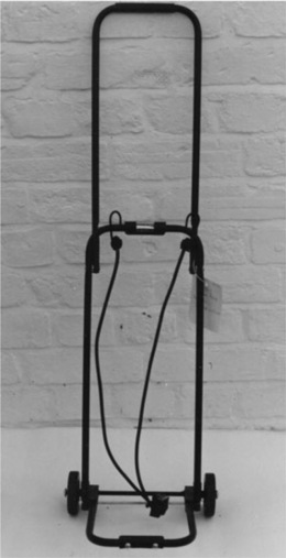
The carriers are familiar to all travellers, and consists of a folding metal frame fitted with two wheels at one end, the upper arm of the frame unfolding to form a handle for the user to pull the trolley along. It is locked by a plastic clip. The lower part of the frame folds out to form a platform on which luggage can be placed, and is kept in position by a bungee cord attached to a plastic fitting riveted to the frame. The bungee cord is strained over the luggage and the hooks at either end linked to the frame. The plastic fitting has two feet so that it will rest against the floor when at rest. When not in use, the frame can be folded up compactly for storage (Fig. 10.24).

10.6.1 First accident
An accident occurred in 1985 shortly after the carrier had been bought three days before, and was being used to carry luggage. As one might expect, it had been used for carrying about 30 lbs of luggage, had been folded, and used again. It failed suddenly when the user was in a lift, (so not under any extra loads from movement or impact), the bungee cord sprang back and the broken plastic end hit the user in the eye. Despite several operations he later lost his eye and sued the supplier and manufacturer. The plastic component had broken across the centre line where it was riveted to the metal shaft (Fig. 10.25). The fracture appeared very brittle, and it was the sharp edges to the break which caused the damage to the user.

10.6.2 Fracture and other surfaces
Examination of the fracture surface showed several revealing features (Fig. 10.25). The fracture surface could be divided into four zones (K1 to 4 in the figure) separated by the two rivet holes, and a clear crack junction shown by the arrow in the picture. There were also several polished zones near the lower edge of the sample where it abutted the steel frame (D). The surface was splattered with small spots of white paint, apparently when being stored in an office prior to our examination.
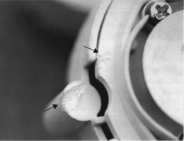
The end showed that the prominent blocks had been deeply abraded by contact with the ground, as would be expected since they would have supported the luggage when the trolley was at rest (Fig. 10.26). When the bungee cord was removed, it exposed the gate from which molten polymer would have entered the tool during processing to shape by injection moulding, as well as several weld lines formed around the gate by cooling polymer not fusing correctly. The weld lines were more extensive over other parts of the failed component, and one could be seen aligned and merging with the main fracture surface on the side of the part (Fig. 10.27).


The component was moulded into a four cavity tool, and the failed part came from cavity No 4 of the tool. New samples were requested from all cavities, and comparison showed weld lines were present on all the samples. They all showed signs of distortion as well as splay marks on one sample, indicating wet polymer. The sample from cavity 4 showed the most extensive set of weld lines, sink marks and general distortion. The material was high ethylene content (ca 7%) polypropylene, which is normally tough and ductile, but as with all such materials, brittle behaviour can occur from design defects, poor moulding practices, contamination and so on. But degradation at least could be ruled out, because the FTIR spectra showed no trace of oxidation and DSC showed nothing amiss in the thermal behaviour of the failed or intact components. The data were compared with standard granules of the polymer with good correlation. There was some evidence for a whitened origin in K1, but did not appear in the other parts of the section, so contamination seemed unlikely, but it was a conclusion which was modified after the second accident.
10.6.3 Failure sequence
It was most likely that the weld lines had been opened during the riveting operation at assembly which put a high compression load on the component. The open cracks would have been quite invisible to external inspection, since the outer polished areas (D) do not run into the external surfaces, but are hidden inside the device (Fig. 10.25). In any case, this part where it is joined to the frame has the smallest cross-section of the component, so will be the weakest part of the whole component when subjected to bending from the bungee cord. The overall cross section measured 70 by 25 mm, while that of the joint was 70 by 7 mm, so formed only 28% of the total section area. When the cord was fully stretched, it would exert a tensile load of about 5 kgf on the section.
All loads would have been concentrated here, where the round holes for the rivets concentrated the local load yet further by about a factor of three. However, the cracks appeared to originate at or near the tips of the open weld lines, so they were the more serious stress raisers in the system. Those open cracks lowered the section even more since they were so large and deep. The deepest weld line in Fig. 10.25 lay near K2 and penetrated the section by about a third, so was the most likely point from which failure of the component started. Once fast fracture started here, the rest of the section parts would quickly follow from their shallower weld lines in a chain reaction. The severity of the defects explains why it failed when the trolley was simply standing in a lift, although no doubt the intermittent loads when moving helped to pull the weld lines further apart.
The company making the trolley made several points in its defence, mentioning that over 100 000 had been sold into the market without reported failures of this kind. If the accident had indeed been unique, then it pointed to a sudden deterioration of moulding conditions, perhaps s symptom of wear-and-tear in the tool used to make the parts. Such wear is inevitable after long runs, and can be seen by a fall in the quality of the mouldings with time. A well run QC department should spot this kind of problem by preserving original mouldings as well as by careful testing of a sample of parts taken from batch production runs, for example.
10.6.4 Conclusion
Since the case was already being contested by the defendant moulding company, an opposing view of the accident was produced by independent engineers. Their report was disappointing for the absence of any serious study of the failed product at all. Rather, it was a critique of our work with many uncorroborated statements. Such reports are not uncommon unfortunately, but if the case had gone to court, would not have withstood scrutiny by an alert cross-examiner. They concluded that the company were not to blame and the failure was attributed to poor assembly by the manufacturer, and abuse by the user. The latter allegation is also very common, but ignored the evidence of failure within three days of purchase and our direct examination of the abrasion evidence from the failed component (Fig. 10.26). The independent engineers seemed to have little knowledge of the way products are moulded and the defects of poor mouldings.
It was apparently a unique failure that could be explained by a maverick moulding. Weld lines can vary greatly in position even when in a single batch, and it was the coincidence of several weld lines with the smallest section which produced such a poor component that it failed within a few hours of first use. But shortly afterwards, there was dramatic confirmation of our conclusions, which led to final settlement of the case.
10.6.5 Second accident
Alarm bells rang at the insurer’s when an identical trolley failed in exactly the same way and injured another user (Fig. 10.28). The first accident might be a quirk of fate, but a second suggested a serious underlying problem. The risk of yet further incidents rose sharply, a warning no insurer could ignore. Although the effects were less serious, the user was still severely injured when the sharp plastic part sprang back suddenly into her face. Because she was taller than the previous victim, the end hit her in the mouth rather than her eye, but she still needed medical treatment with stitches to close the open wounds.
The accident happened four years after the first, in 1989, so was recent and the evidence correspondingly fresher. The failure prompted rather more extensive research into the quality of the material of the mouldings as well as more detailed microscopy, both areas being easier to conduct given earlier experience with these mouldings. It was clearly vital to get to the heart of the matter and so prevent further failures.
10.6.6 Fracture surface
The fracture occurred in exactly the same way as the first, although there was no trace of opened weld lines at the base of the section (Fig. 10.29). But there were clear and distinct origins (O1–O4) in each of the four sectors marked by convergence of hackles. Close inspection using the optical microscope showed distinct particles at each of the four origins, those from O1 and O2 being shown in Fig. 10.30. The particle at O1 seemed dark in colouration and was surround by a white or grey halo, while the particle at O2 appeared to be a tiny granule of clear or white appearance. It was also surrounded by a lighter halo, as well as black particles and reflective particles, which could actually be seen by the naked eye when turned in the light. SEM was the obvious method to explore their nature.


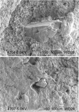
SEM proved very revealing (Fig. 10.31). The particle at O1 was actually a porous material within which was embedded a solid particle with the distinctive fractures of broken glass (conchoidal facets). A survey of the adjacent surface showed yet other particles which appeared more rounded, suggesting river worn sand surrounded by a void. Such particles should be susceptible to X ray analysis within the instrument and the resulting very simple spectrum confirmed the attribution of the central particle at O1 (Fig. 10.32). Despite being gold coated, the particle showed the characteristic peaks for silicon and oxygen as required by the formula SiO2 for silica. Other spectra showed more complex combinations of elements, such as those interpreted as alumina-silicates, minerals common in soil and rocks. Such particles weakened the material substantially because they acted as stress concentrators in the material. Voids could be formed as the plastic cooled after moulding since the coefficient of thermal expansion between dissimilar materials, such as glass and organic polymer, is very large. Such voids form around the particle and then act as stress raisers, the exact value of the effect depending on the precise shape of the void.

The polymer was extracted with solvent and thin films cast for FTIR spectroscopy and comparison with standards. The tests showed the polymer to be identical to the previous trolley parts. DSC and GPC analysis con-firmed the conclusion with an identical melting point and of similar molecular weight to the standard.
10.6.7 Contamination
But the material was obviously badly contaminated, but where did it arise and why? One way of tackling the problem afresh was simply by complete dissolution of a component using hot decalin solvent, the same solvent used to make thin films for spectroscopy. Two samples were analyzed: a small (3 g) part of the failed product and a new intact part. The hot solvent was filtered and washed, and the debris collected for inspection (part of the intact sample debris is shown in Fig. 10.33). Although most of the debris collected proved to be carbon black filler, there was one notable exception: a large black beetle (lower right). The failed part was slightly more contaminated than the intact part at a level of about 0.1% by weight. More detailed examination showed the following variety of materials:

The beetle was tentatively identified as being suggestive of the family Staphylinidae or rove beetles, the largest member being the familiar Devils coach horse. So where did this strange collection of debris originate? The metal and wood shavings suggested a toolroom or workshop origin, although wear within moulding machines can also produce metal fragments. The duplex particle at O1 was probably a bitumen seal reinforced with sharp sand, and often used to seal concrete floors, suggesting an industrial factory such as the moulding shop itself. But why? It may be that operatives were encouraged to conserve polymer pellets by sweeping up spillages on the floor and putting them back into the hopper supplying the moulding machines. If that was the case, then it was deeply misguided policy because it weakened the products used in the trolleys and endangered users. The fact that similar contamination was found in both a failed and intact component indicates it was a policy used for some time.
But the final irony of the case lay in the design of the trolley. The bungee cord which exerted the pressure on the plastic attachment need not have been tied to that device at all, so in a later modification, it was tied directly to the frame and became independent of the fragile plastic attachment. There was now no chance of the frame failing and the bungee flying up and hitting the user. One wonders why this simple solution was not adopted in the first place and so saved considerable anguish of two injured consumers.
10.7 Failure of ABS joints on bike carriers
Car use has grown greatly during the past few years, and with it the development of a range of accessories enabling leisure products to be transported easily on the roof or rear (Fig. 10.34). In this particular incident, the driver was returning home from a holiday in the Lake District in 1996 when the device suddenly failed and three bikes on the frame were thrown into the road. Fortunately there was little other traffic, and he was able to stop and retrieve the bikes before they could cause a serious accident. However, the bikes were badly damaged and he made a claim against his insurers. He said that he had strapped the bikes down to the frame as recommended in the instructions, but that the straps came away when the bikes fell. The insurers approached us to determine the likely cause of the failure.

Bike carriers consist of steel frames assembled together and supported by the car (Fig. 10.34). The frames are connected together by two plastic clam shells at joints between the steel parts. A bolt passes through each assembled shell and both steel tubes. The edges of the shells are serrated and mesh with an identical set of teeth in the opposing shell so that the angle of the top bar which supports the bikes can be varied by the user (Fig. 10.35). The picture shows the intact but broken joint on the left-hand side of the top part of the carrier. The opposite joint had also broken but only one half had survived (Fig. 10.34). One of the shells or cups had been lost by dropping onto the road, and was not found. The two top joints had been fitted in reverse with the handles on the inside rather than the outside as recommended.

FTIR spectroscopy showed that the polymer was ABS, a normally tough material capable of resisting imposed loads, although like all notionally tough materials, can suffer brittle fracture with intense local loading. There appeared to be no degradation of the polymer from the spectrum, and the thermogram appeared normal with a Tg at about 107 °C. The packaging for the device stated that the material of the connectors was nylon.
10.7.1 Damaged shells
The broken surviving joint was now the focus of attention, despite the fact that part of the opposite joint had been lost and where the failure may have started. Each of the cups comprising the joint were injection mouldings with a gate at one side of the shape (Fig. 10.36). Each cup was reinforced internally by a set of four ribs set at right angles to the semi-circular recess which enclosed the steel shaft to which the shell was attached. There was a central hole for the steel bolt, the shank of which was equipped with a single steel washer. The shank fitted well into the hole with little clearance, leaving no space for rubber bush or any means of absorbing vibrations from the car. However, it was noticed that the long bolt was slightly bent at one end, presumably as a result of the incident. The opposing bolt was also slightly bent as well. The outer edge of each cup comprised numerous triangular teeth, which meshed well with another set on the opposing cup to form a tight joint.

The fractured cup showed a main fracture from the root of a tooth, a crack which had grown into the adjacent rib and along the part next to the steel shaft but missing the central bolt hole (Fig. 10.37). It had branched several times. Part of the cup edge was missing, presumed lost. Another crack had been initiated almost diametrically opposite again at the root of a tooth, and it had also grown into the shell and part way along the shaft part, but halted. The sub-critical crack had presumably grown at the same instant as the main crack and been halted by loss of the main load of the bikes suspended on the frame.

The main fracture itself was quite clearly an overload crack, since there was no trace of any striations or other indicators of fatigue (Fig. 10.38). The gate was situated about 90 degrees away from the crack origin, and a faint weld line could be seen near the central bolt hole, but was not associated with any cracks. The opposing cup showed no cracks at all. The single surviving cup from the failed joint opposite also exhibited no cracks but did show some damage to the sharp tips to the teeth. About ten teeth were damaged, probably indicating where the missing cup had jumped over them when the joint failed.

All the cups were examined for their design and any possible defects. There were no visible defects, although all showed very sharp corners both at the teeth roots and at internal ribs. Those on the roots varied from extremely sharp (ca 0.01 mm radius of curvature) to a larger value of about 0.05 mm. The value changed in a regular way around the circumference, and the tool was probably made by a CNC machine. But the failure in the opposite cup had occurred at a root of about 0.05 mm rather than the lower values.
10.7.2 Stress analysis
Knowing the total weight of the three bikes of about 45 kg, it was possible to analyze the loading situation. The total moment acting on the joint allowing for the different distances at which the bikes were suspended was about 95 Nm, reducing to about 89 Nm to allow for the angle of inclination of the bars to the horizontal (20 degrees). So the load on each shell was calculated at about 110 kgf, a large value owing to the leverage effect of the suspended bikes. But that load would have been shared by the teeth edges, so the net effect on any one tooth would have been affected by the localized strain on the teeth at maximum loading. Although the teeth meshed closely under no load, the effect of loading could have concentrated load much more locally. The abrasion marks on the isolated cup was suggestive but not conclusive, since some such damage would be expected when the teeth slipped past one another.
What is certain, however, is that the root of the teeth would have acted as serious stress raisers, the exact value depending on the radius of curvature at the root. One estimate using a diagram from Peterson (5) suggested a value as high as Kt ∼ 12, but such was likely to be an over-estimate since surrounding roots would lower the net effect (6).
10.7.3 Conclusions
Since the failed cup was missing, it proved impossible to pinpoint the precise failure mode, a not uncommon event in many accidents. However, it could well have failed by fatigue from a root on the missing part. Since the radii there varied greatly, it is possible that the very sharpest roots were present at the position of maximum load and a fatigue crack grew from that point. The entire frame would transmit much of the vibration to which cars are subjected during normal driving, let alone driving on rough roads of which there are many in the Lake District. Although rubber pads were provided where the frame met the car boot lid, there was very little to prevent vibrations from reaching the upper part of the frame and the supported bikes.
However, could failure to erect the frame correctly have caused failure? There was no evidence that the bolts had slipped round, so was an unlikely possibility. The Italian company who made the frame pointed to this explanation in their response, but it could not explain the fracture of one cup and the likely fracture of the other and its loss from its position. They insisted that they had always used ABS for the part despite the statement on the packaging, and further stated that the design had been approved by an independent test house (TUV in Germany). No details were given, however, and it was unclear what tests had been performed. They did admit that the shells ‘might have some problems’. It was likely that a faulty ABS shell was the cause of the incident, and its design improved very easily by removing harmful and sharp stress raisers at the teeth roots. The driver was compensated for the loss of three bikes.
10.8 Failure of HDPE baby cot latches
The baby cot is a familiar item to all parents, and one expects that all parts are safe when the cot is in use. But one such cot did fail and a 20 month-old child fell and broke his arm as a result (Fig. 10.39). The part which failed was a plastic latch which was fitted to the top of one of the rails. It was designed to hold the sliding side of the cot in position, but could be released so as to allow access to the interior. The fracture allowed the baby to put pressure on the side, which fell further down since it was supported only at one side, and he toppled over onto the floor. His mother spotted the fractured component after the baby had been rushed to hospital and she returned home to his bedroom.

10.8.1 Broken latch
The latch was a simple moulding which possessed a central hole to fit to a boss attached to the cot, yet allowing rotation to hold or release the side (Fig. 10.40). The picture shows the intact latch at left, the fractured boss at right. The platform on which the top rail rests had fractured along the corner with the upright in a totally brittle way. Load on the platform will have put the shank of the latch into tension, which would have been concentrated at the sharp corner moulded into the design.

Direct examination of the fracture confirmed that the main and first crack started at the corner about halfway along its length (upper Fig. 10.41). Hackles in the fracture surface led back to a point in the corner, and there were traces of striations concentric to the point, which suggested a fatigue mechanism (O1). But there was a second crack, which probably started after the first since there was a clear origin (O2) on a wing of the component (lower Fig. 10.41). The junction between the two crack paths was visible as a sharp line in the fracture surface. Since the part where the second crack started would not have been loaded at all heavily when in use, a badly moulded part was likely. It was confirmed by examination of the rear of the parts, where a deep moulding mark was visible (Fig. 10.43). The same pictures also show the gates (G1 and G2) at the side of the moulding where molten polymer entered the tool.


Analysis of the polymer using FTIR spectroscopy and DSC showed it to be high-density polyethylene, and there was no significant difference between the intact and fractured samples. The melting point was centred at about 133 °C. Although small carbonyl peaks were detected in thin shavings cut from both samples, they were identical in size and not significant.
10.8.2 Analysis
The failed latch had failed suddenly from the sharp inner corner to the platform holding the rail of the cot, so allowing the baby to fall and break his arm on the floor. The latch failed owing to poor moulding practice or quality control at the injection moulders. Melt fracture lines are seen in products where the melt is either too cool when it enters the tool, or the tool itself is too cold, and is similar to the weld lines which form when cooling melt fronts impinge. The critical fracture started at a very sharp corner (radius of curvature ca 0.2 mm) to the platform supporting the rail and would have been loaded intermittently by the baby leaning and pushing down on the rail in addition to supporting the relatively low static load of the side of the cot (Fig. 10.40).
The stress concentration at the sharp corner was exacerbated by the likely presence of a melt fracture line here, formed by cold or cool moulding, producing a net stress raising effect estimated at about five times the maximum nominal stress at the origin using standard diagrams of the stress concentration effect (7,8). Such defects are produced by oscillations in the melt front, an instability produced by the lower temperatures present at the start of a moulding cycle, for example. If an early moulding, the faulty component should have been removed and scrapped, but it unfortunately entered the product stream and was used in the cot.
The accident highlighted the problem of correct and unacceptable design practice, both in terms of geometrical design of components and manufacture to shape. While HDPE was an acceptable choice of material, like all nominally tough and ductile polymers, it will behave in a brittle fashion when severe defects are present. Sharp corners are totally unacceptable in modern design practice, and have been the cause of many premature fractures of safety-critical polymer components. But moulding practice, too, demands high standards of quality control, inspection and testing to weed out faulty parts before they enter the marketplace. If they do, then consumers are put at risk of sudden failure of a part they rely upon for safe use of the product. The failure was likely caused by a moulding defect coincident with the corner, so that the product was a maverick, since no widespread failures were reported at the time. Child safety demands that special care is taken with the design of critical components in products used by children, and cots are covered by BS 1753:1987. The standard (9) specifies a strength test for cot latches of 90 N, but fatigue problems are not mentioned. Falls are one of the most common injuries to children accounting for about 10 deaths per year in the UK according to RoSPA (10). Toys, for example, are subject to strict regulation after numerous swallowing accidents, as are car seats. Many safety devices have been developed to protect children from home hazards where most of the accidents occur, but demand good design and manufacture to ensure that they fulfil their intended function. The family involved in this incident were compensated for their distress.
10.9 Conclusions
The present chapter has discussed a number of product failures of consumer products caused by a relatively small number of failure modes. All could have been prevented by appropriate action before the failures occurred, some actions easy, if not trivial, to carry out in practice, others involving awareness of best advice in manufacture. Above all, designers must specify correct procedures after rigorous and meaningful testing of prototypes or early versions of products before launch into the marketplace. It is the user or consumer who has to rely on those products, especially those where their personal safety depends on product integrity and strength.
The defects identified as the source of the problem can often be difficult to spot before failure occurs, especially where the part has been moulded under poor conditions and the product appears to all intents and purposes, dimensionally correct and fit for its intended purpose. But then it cracks up when only a small pressure or stress is used, such as when a plug disintegrates when pushed into a socket. The investigation that follows is frequently now made more difficult by the widespread locations of those who need to be consulted, the raw materials supplier, the processor, the moulder, the assembler and the consumer in some cases. The chain of production and supply is often very long, making the task of follow-up and analysis convoluted and time consuming.
Some simple ideas can be of immense assistance in the early days of investigation, such as identifying when the product was made and if the problem only occurs in a specific batch of products, for example. It assumes complete traceability from identifying features or logos on the product, now an increasing requirement in many standards. That proved possible with the fractured Noryl plugs, and reduced the analytical effort substantially. Since the failed plugs came from a single month of moulding, the records then became a crucial part of the investigation, but only those from adjacent weeks were made available. They pointed strongly to cold moulding as the source of the problem.
But then another investigator came to quite a different conclusion as to the source of the problem, and his conclusions had to be checked independently. They turned out to be wrong, and not supported by our evidence. However, contact with the moulders in Shanghai showed that tool conditions had been modified and production resumed with better safeguards in place to prevent a repetition of the problem. Similar moulding problems occurred on the much more dangerous high voltage supplies on busbars, and were resolved quickly by direct liaison with the local moulders.
A quite different type of problem arose with a new design of RCD safety plug, which appeared to infringe an old patent. The trial revealed the nature of the device: it was based on mechanical action triggered by an arm held by an solenoid. When the solenoid detected a drop in voltage, the arm upset the equilibrium of a set of activated levers and spring action disconnected the contacts and cut the power to the external supply very quickly. The speed of reaction of such devices is critical to prevent electrocution: it must be lower than 50 milliseconds and the new design offered a new and possibly faster way of reacting to a sudden leak such as caused by a power tool accidentally cutting the leads. The defendants in the action succeeded and the price to the consumer has dropped substantially with the competition between different devices.
Another kind of intellectual property problem was illustrated by the introduction of a new kettle switch from China. It infringed UK patents and analysis of the polymer used in its construction showed that an unsuitable flame retardant had been added to the bulk polymer. The retardant decomposed during moulding and created large holes in the switch, endangering its function. Encouraging manufacturers to work with patentees under licence gives access to know-how and expertise, so improving product safety. The problem of policing patents worldwide continues.
Polymers have been adopted for use as connectors in many consumer products, and three problems were described and analyzed. A small luggage trolley failed twice and injured users in exactly the same way on both occasions. A polypropylene fixing was attached to the base as a prop for the loaded trolley, as well as holding the knotted centre of a bungee cord for holding the luggage in place. The first failure of the fixing led to the loss of an eye when the part fractured suddenly and the bungee rebounded into the user. The fracture was caused by weld lines from poor moulding practice. The second failure injured a woman user, and was caused by particulate contamination, most likely sweepings from the factory floor added to the hopper. The part was poorly designed to resist bending stresses, and was unnecessary anyway. The bungee was attached to the steel frame as a much more stable connection, and the plastic moulding eliminated entirely.
A bike frame attached to the rear of a car failed suddenly and three bikes were lost into the road and destroyed. One cup of an upper joint in ABS probably fractured by fatigue from a sharp tooth corner, and the second joint fractured by overload at a similar corner. Sharp corners will weaken any tough polymer, and good practice demands that large radii of curvature are always specified in polymer products. Even if normally unstressed, a sharp corner can cause sudden failure when least expected. A baby cot latch failed in a similar way from a sharp corner in fatigue, and a baby fell from the cot and broke his arm, reinforcing the message about geometric stress raisers in safety-critical products.
What more general points can be made about these failures? There is great pressure on component suppliers such as moulders to maximize the return on the large capital investments in machines. But that should not encourage poor control of component quality or poor moulding practice, such as reducing cycle time to maximize production rate. Designers should test products thoroughly before launch of a new device to at least to current standards, and often beyond, simply because many standards set minimum levels of compliance, and are frequently outdated by the time they come to be published. Product testing itself is an art because it is often difficult to determine what stresses and environments a product may encounter in its normal life. But the design should always allow for worst possible loading, and especially fatigue loading, where even a low load applied intermittently can initiate brittle cracks at stress concentrators. The user is often unaware of hairline cracks because they may not be visible at all when the product is unloaded, or in an obscure position quite out of sight.
There is no doubt that modern communications such as email messaging have improved the feedback loop between interested parties during failure analysis. The web has opened up vast areas of technical information to designers so that product performance can be improved before introduction into the market. Some skill with key words is needed in finding the precise information needed to solve a particular problem, and there is still a general lack of case studies of failed products and materials. Basic knowledge of the role of stress concentrations in promoting premature fracture still seems to be lacking, however, and understanding of the principles of injection moulding is still at a rather primitive level. Wikipedia articles on the problem are a helpful source of information and a starting point for designers seeking help.
A final point can be made about the importance of failures to designers. A frequent response is simply outright denial of any responsibility, an attitude which is not helpful to either the complainant or claimant, or the designer and manufacturer. Once a cause or causes are established, it must be addressed if further failures are to be prevented. Insurers in particular will be unhappy if an underlying design defect in a product is found, and not addressed by the designer or manufacturer, because they have to assume responsibility for compensation. Designers should, on the contrary, regard failures as feedback from the market, and re-examine the problem with a positive approach. Only in that way can product design be improved, and indeed, itself become a selling feature.
10.10 References
(1) GE Plastics, B.V.Technical Manual: Noryl Profile. The Netherlands: Bergen-op-Zoom, 2000.
(2) Wright, David. Failure of Plastics and Rubber Products. RAPRA Technology Ltd, 2001; 276.
(3) BS 7671, Requirements for electrical installations. IEE Wiring Regulations. Seventeenth edition, 2008.
(4) Lewis, Peter Rhys, Reynolds, Ken, Gagg, Colin, Forensic Materials Engineering: Case Studies Chapter 13, p. CRC Press, 2004:414.
(5) Peterson, R.E. Stress Concentration Factors. Wiley-Interscience; 1974. [Figure 15.].
(6) Peterson, op cit, Figure 13.
(7) Peterson, op cit, Figure 205.
(8) Young, Warren C., Roark’s Formulas for Stress and Strain Table 37, p, 6th. McGraw-Hill, 1989:740.
(9) BS 1753, Safety requirements for children’s cots for domestic use, 1983.
(10) Further information available from the Royal Society for the Prevention of Accidents website at http://www.rospa.com/.