
Components in transport applications
9.1 Introduction
Car use is so ubiquitous that it is taken for granted, but yet the number of accidents remains high despite the many measures taken to reduce them over the years. They are still one of the most common causes of death and serious injury, with 53 485 in 1992 dropping 39 407 in 2002, of which there were 4229 deaths in 1992 and 3431 in 2002 (1). Although the UK has the lowest death rate of European countries (6.1 per 100 000 population in 2001), it is small consolation to the relatives of those victims, or the large number of injured motorists. The main causes are adverse weather, alcohol consumption and excessive speed, causes which have been tackled by tougher legislation and changes in social attitudes.
There is no doubt that car design has also improved dramatically over the past 20 years, with improvements in passenger safety including seat-belts, airbags protecting against frontal impacts, more efficient brakes and protection zones designed into the structures of cars. Critical car components have improved lives and reliability, the car tyre being an outstanding example, where the radial has now all but displaced the cross-ply tyre. Sudden blow-outs are now much rarer than formerly. Laminated glass has replaced toughened glass windscreens, so driver vision is retained despite severe damage, since the fractured parts are held together by a viscoelastic interlayer, a polymer polyvinyl butyral (PVB). Composite materials have displaced many metal parts, and promise to displace yet more, as their lower weight and better impact resistance offer greater fuel efficiency and safety: nowhere more dramatically shown than by the crash resistance of Formula I racing cars. But there are still many vulnerable components, such as fuel lines and brake seals, for example.
Other users are prone to accidents, especially motorcyclists: two wheels are inherently less safe than four when traction on the road suddenly drops, for example. Diesel fuel spills on the road are an especial hazard for motorcyclists. When a bike is involved in an accident, the machine inevitably falls over and the user is usually thrown from the machine, and can sustain horrific injuries since he or she will be travelling at the same speed as the machine. There are no seatbelts for motorcyclists and they are directly exposed to the weather, while improved engine design has led to the potential for much higher speeds than is normally achievable in four wheel vehicles. Thus motorcycles have 120 deaths or serious injuries per 100 million vehicle kilometres travelled, compared to a figure of just 4 for motorists (using UK DOT statistics for 2005). Both rates have been decreasing, but the disparity between motorcyclists and motorists reveals the far greater hazard of driving on two wheels rather than four.
9.2 Failure of tailpack in a motorbike accident
The hazards of motorbikes are nowhere more revealing than in the following case of a biker who lost part of his leg during an accident which occurred in France in 2002. The accident involved a troupe of bikers who had been travelling together, travelling to Tours to watch the Le Mans Grand Prix race on 17 May in clear, dry weather. As they were travelling along the A28 motorway in northern France, the tailpack of the leading biker (on a Yamaha 600 cc bike) suddenly became detached from the rear pannier of his machine and fell from the back of the bike. It became entangled with the rear wheel, causing it to seize suddenly. Since the machine was moving at speed, it skidded and the biker was thrown clear. However, the biker behind him swerved to avoid the fallen bike, and he himself skidded and was thrown into the carriageway. Unfortunately, he slid into the central reservation, where a steel post holding the barrier severed his leg below the knee. His life was saved by the ambulance team which arrived, and by subsequent treatment in the local hospital. After recovery, he sued the lead biker of the group and the maker of the bag which had fallen from the rear of the motorbike. The tailpack had been in use for about a year after purchase.
9.2.1 Seized wheel
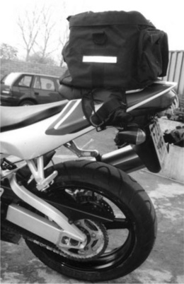
The local gendarmerie examined the accident scene very soon afterwards and recorded the state of the vehicles where they had finally stopped, as well as the various skid marks left by the lead motorbike (Fig. 9.1). The seized wheel was the focus of attention because it might be possible to reconstruct the sequence of events from the position of the bag and its contents wrapped around it (Fig. 9.2). The close-up of the rear wheel seemed to show that a heavy duty steel cable (from a cycle lock stored in the tailpack) was probably the cause of seizure when it became jammed between the tyre and the rear suspension. The damage to the base of the tyre clearly showed the point at which the wheel had locked, with a hole in the tyre surrounded by heat affected rubber tread (Fig. 9.3).


Figure 9.2 The lead motorbike after the accident showing rear wheel and tailpack with bungee cords wrapped around number plate.

The first investigator (acting on behalf of the lead biker) was the first to examine the tailpack following its retrieval from the wheel. He attempted a reconstruction of the fall of the tailpack using the original bike (restored to working order). It had been attached by rubber bungee cords to the rear seat (Fig. 9.4), and the investigator thought that it had slipped sideways so as to jam the rear wheel, as shown by the conjectural reconstruction of Fig. 9.5. There was a problem with the theory, however. When the reconstruction is compared with the actual remains (Fig. 9.2), the position of the black bungee cords is quite different. In the accident, the cords have become wrapped around the rear number plate, while the reconstruction shows no such situation. The way the bag fell during the accident must have been different.

9.2.2 Deeper analysis
To address the problem, we felt that a detailed examination of the actual remains was needed. The tailpack itself was severely damaged, as one would expect from its final position resting on the wheel (Fig. 9.2). There were several tears and abrasion marks on the bag showing where the rapidly revolving tyre had made contact with the outer cover (Fig. 9.6). The lock comprised a thick steel cable about 10 mm in diameter, with a loop at one end and a lock at the other (Fig. 9.7). The two ends had been originally given further protection by PVC sheaths covering the outer parts, but they had become severely damaged when in direct contact with the moving wheel. The damage pattern showed that the lock and loop were near one another in a tighter loop than shown in the picture, judging by the black PVC transferred from them to the adjacent cable. The polymer had been melted by the frictional loads from the tyre, and its transfer showed the original configuration of the coiled cable. Since neither lock nor loop is visible in Fig. 9.3, they must have been under the tailpack and facing forwards. So what can be said about the original position of the tailpack?


One reference point is the white flash tape fixed to the large panel of the tailpack seen in Fig. 9.6, and visible in the accident (Fig. 9.2) and the reconstruction (Fig. 9.4). The position after the accident was consistent with the reconstruction, but another point arose about the contents of the bag and what their position told us. According to the statement of the biker who packed the tailpack, it contained mainly clothing (jeans, T shirts, socks, underpants, trainers, a sweat shirt and wash bag, helmet visor, documents, nylon waterproof jacket and the bike lock). We estimated the total weight of clothing as about 5.6 kg, and the lock weighed 1.2 kg, giving a total of 6.8 kg. The only items which were clearly identifiable were the lock and the blue jeans (Fig. 9.2 and 9.3), so the rest must have been buried out of site within the bag. The fact that the lock came into contact soon after the bag fell suggests that it was packed outside (a cargo net was used on the bag), perhaps on the top. Since the lock was the heaviest single item, its position could have made the tailpack unstable when in its original position on the rear seat (Fig. 9.4).
9.2.3 Bungee cords
The final point of interest was the role of the straps and bungee cords: were they sufficient to hold the tailpack securely? There were two bungee cords attached to the base of the bag and they were apparently the only way of securing the bag to the bike. They were meant to be looped under the seat and then re-attached to the bag by D-rings sewn into the outer fabric of the tailpack, as suggested by the reconstruction. That meant some sacrifice of lateral stability, as already shown above. Bungee cords are composed of a core of continuous vulcanized rubber strips enclosed by a woven fibre sheath. The sheath is easily deformed, so the physical properties are mainly determined, at least initially, by the elastomeric core. However, the sheath limits the maximum strain to about 200%, the inner core being capable of much greater extension.
In the first place, the bungees from the tailpack were of relatively small diameter (about 6 mm) compared with the bungees on the new bag bought by the first investigator of nearly 8 mm diameter. He stretched the bungees from the accident out under the seat (Fig. 9.4) and found that the front cord was stretched 1350 mm and the rear bungee to 900 mm, and by performing simple tests estimated that the front cord exerted a tension of 2.45 kgf, and the rear cord only 0.9 kgf. Moreover, the stress exerted by the cords relaxed with time, falling to about 2.2 kgf and 0.7 kgf after 30 minutes. We confirmed the results by conducting creep experiments where cords are subjected to a constant load and the change in length determined. After 30 minutes, the length increased by about 10%, so one would expect a drop in stress of about 10% for a highly stretched bungee.
The experiments showed that the force holding the bag in place dropped significantly after 30 minutes, so making the tailpack less secure than the user might have expected. So not only were the bungee cords weaker than on a new tailpack of the same make, but they were also less reliable than, say, a simple rope, owing to stress relaxation with time. The relaxation is probably caused by slow movement of the textile sheath as the fibres pack together more efficiently under load. Stress relaxation in the rubber cords is much smaller by comparison.
9.2.4 Alternative theory
It was more likely that the tailpack had fallen backwards from the rear seat, and then become entangled with the wheel. The final position of the bungee cords supported the idea because they were both draped over the number plate (Fig. 9.2), and not under the rear seat, as in the reconstruction (Fig. 9.5). Moreover, there was little evidence of any side winds at the time of the accident, and indeed, the only air movement will have been by virtue of the speed of the motorbike. It will of course have been acting along the axis of the bike tending to overturn the bag over the rear of the machine (Fig. 9.6). Thus if the bike was moving at 50 mph then the front face of the tailpack would be pressed rearwards by the wind force.
It remained to estimate the turning moment from known loads and forces acting on the tailpack (Fig. 9.8). The force exerted by moving air can be calculated using the following formula (2):

where V is the air velocity in miles per hour (mph) and P is the air pressure in pounds per square inch (psi). So a vehicle speed of 80 mph produces a wind pressure of 0.13 psi (or 91 kgfm− 2 in metric notation).
The area of the tailpack facing the air flow is about 0.3 metres square, so the net force, F acting on the bag can be calculated from the formula:
where A is the area facing the air flow. Hence
when the motorbike speed is 80 mph. This force will exert a moment, M given by the formula
Where d is the distance from the centre of gravity of the tailpack. Taking that point at dead centre of the bag, then the moment, M1 is
That moment produced by the air acting on the tailpack will be opposed by the force of the bungee cord of a maximum of about 2.45 kgf. If the rear edge of the seat (the rear corner of the bag) is the pivot, then the moment from the front cord, M2 would be
But there is another moment which must be taken into account, the inertia of the bag itself (of weight 6.8 kg):
So the total moment, MT acting against the air pressure is simply:
The figure is less than the moment produced by air flow of 1.23 kgf-m, so the bag will not overturn when the motorbike is moving at a speed of 80 mph.
9.2.5 Critical speed
The question then arises of what speed will cause the bag to overturn. The critical pressure Pc must equilibrate with the greatest moment resisting overturning of the bag, so
So Pc = 1.755/0.01305 = 134.5 kgfm ‐ 2 or 27.65 psi
But by equation 9.1,
So (Vc)2 = Pc/0.003 = 27.65/0.003 = 9167
Hence Vc = (9167)1/2 = 95.74 ~ 96 mph
The speed of the motorbike must exceed about 96 mph before overturning of the tailpack can occur. There are many assumptions built into this simple argument, such as the effect of the driver’s body on airflow onto the bag and uncertainties in the exact way the bag was attached by the bungee cords, for example. It is also questionable that the centre of gravity was at the mid-point, especially if the heavy bike lock was placed on the top, as seems likely from its resting position on the rear tyre (Fig. 9.2). It would, however, make toppling of the bag more likely at a lower speed.
9.2.6 Skid mark analysis
An independent report was made on the likely speed of the motorbike from the length of the skid mark made by the lead motorbike (Fig. 9.1). Using kinematic analysis applied to the length and orientation of the main skid mark, the report concluded that the bike must have been travelling at 98–102 mph when wheel seizure occurred, a result in agreement with the stability analysis shown above. The kinematic result was also in agreement with known times of departure from the last halt, the time of the accident and the distance travelled to the accident site.
As in many witness statements produced in vehicle accidents, the speeds were under-estimated when compared with the inferences made from the physical remains. This is what the driver of the lead motorbike stated: ‘we had been travelling at around 80–85 mph … I remember being on the outside lane and the bike snaking. I remember nothing until I awoke in the recovery room at the hospital.’ The speed limit on the motorway at the time was about 80 mph. The biker added that the group had been travelling for about half an hour before the accident, although the bag itself had been fitted well before, so stress relaxation will have weakened the tension in the bungee cords.
9.2.7 Tailpack design
The design of the bag, especially the first version bought by the biker, was deficient on several grounds. The two bungee cords provided were much too small in diameter to provide enough tension to give a secure restraint when fitted to the rear seat, and such cords are in any case poor attachments owing to stress relaxation. The design did not allow for the longitudinal securing of the bag to prevent air pressure acting against the exposed surface of the bag, a severe deficiency since air pressure would act against the bag tending to topple it from the bike, and then, almost inevitably, into the rear wheel. Given that most motorbikes can travel at speeds in excess of 100 mph (sometimes greatly in excess), any accessories designed and sold to be fitted onto the exterior of such machines should be capable of resisting high air pressures. It implies that they should be streamlined and present a minimal area of exposure. In fact rigid panniers are available, firmly attached to the frame of the bike, and are preferable for carrying travel goods (albeit at greater cost). It was unclear whether the manufacturer had carried out tests to ensure the security of the tailpack, such as wind tunnel tests, for example.
When the case had progressed past exchange of the several expert reports, disclosure from the defendants proved revealing. There had been many similar accidents from this design of bag, some involving fatalities.
The accident in France in 2003 was in fact the twelfth of a series of accidents where failure of the tailpack had occurred. The first had occurred as long ago as 1998, when a bungee cord had snapped and the rear wheel locked as the bag fell away, followed by a similar accident a year later, which proved fatal to the rider. A bungee hook had straightened in another, separate accident at about the same time in September 1999. It was the front bungee which failed in these accidents, the critical bungee for opposing air pressure acting on the bag. Further accidents in the new millennium also involved bungee cord failures, probably caused by leverage from the air flow acting against the bag. Another fatal accident occurred in May 2001, the bag having been seen to wobble just before toppling and locking the rear wheel. Further accidents of the same nature occurred through to 2004. The bag supplier, Oxford Products Ltd, was prosecuted successfully by Oxford Trading Standards in April 2003, following the series of similar accidents, and a warning notice published in Motorcycle News the following month. The same company now supplies several different designs of storage bags, which appear to be of much better design, with textile strap attachments preferred over bungee cords.
The case illustrates the importance of designing products which are fit for their purpose under all conditions, especially when travelling at the high speed capability of many motorbikes. While all other parts of motorbikes are very effectively streamlined (including the riders who wear close-fitting leather costumes), it is essential that riders are warned of the importance of secure fitment of accessories, and that those accessories are fit for purpose. The simple analysis of the static equilibrium of the tailpack should have been, in hindsight, applied to the design in question before launch in the market.
Interestingly enough, similar analysis can also be applied to much larger structures, such as bridges and buildings, where stability in the high winds generated in storms and hurricanes is of crucial importance. The Tay rail bridge failed in high winds in 1879, largely because the structure was supported by fatally flawed cast iron towers.
9.3 Failure of drive belts
A rubber composite drive belt is a safety-critical component which transmits power to the wheels of a motorbike or scooter. If it seizes when the machine is travelling at speed, then the sudden stoppage of the drive mechanism will cause a serious accident. Just this happened in September 2001, when a driver travelling at about 45 mph was suddenly thrown from his scooter when the machine seized up, and the scooter skidded out of control. The driver sustained injuries to his arm and wrist. Examination of the scooter quickly established that all the teeth on the rubber drive belt had been stripped from the backing (Fig. 9.9), and clogged up the belt case, so preventing further movement. The scooter had been well maintained, and had only travelled 3012 miles before the accident, after being bought new in October 1999. The servicing manual stated that the drive belt should be inspected every 10 000 km or 2 years, and replaced every 15 000 km or 3 years.

The question arose of the structural integrity of the belt, and whether the belt had failed as a result of an intrinsic defect or by another cause. Since the belt was totally enclosed in a case, it was protected from external damage. A new belt is shown in Fig. 9.9 for comparison.
9.3.1 Belt remains
The first task was to examine the damaged remains, the stripped belt and the many fragments, especially the single and double teeth. The belt consisted of an outer fabric reinforced layer enclosing the glass fibre filament core. There were 51 single teeth in the collection extracted from the belt casing after the accident, seven double teeth and bundles of entangled fibres from the rubber teeth reinforcement. Since the new belt had 77 teeth, there seemed to be a discrepancy in numbers, although it was resolved when enough large teeth fragments were found in the bundle of fibres to make up the numbers. The single teeth were very similar to one another, showing irregular breaks at the junctions between successive teeth (Fig. 9.10). The double teeth were also very similar, most showing incipient or sub-critical cracks between the teeth, where failure had started to occur but been halted, presumably by the sudden seizure of the wheel. But one of the fracture faces appeared quite different from the rest (Fig. 9.11): it is the one at top left, facing right. It deserved further examination after all the samples had been inspected.


Analysis using FTIR and DSC showed the organic fibres to be polyester with a melting point of 257°C, and the rubber matrix probably NBR, or nitrile butadiene rubber filled with fine particles of carbon black. NBR has considerable resistance to swelling by oil, so is preferred for use in engines and drive belts where exposure to oil could occur.
Careful examination of all the fragments in the optical microscope failed to reveal any evidence for possible failure mechanisms such as oxygen or ozone cracking, the former usually being seen as fine ‘crazy-paving’ network of brittle cracks, the latter as deep cracks at right angles to the tension. Both types occur only on outer, exposed surfaces, as does the kind of deterioration seen in vulcanized rubber exposed to active organic fluids such as some oils and some light organic liquids that can swell the rubber. There was no evidence that the material had hardened through exposure to the heat of the engine or friction, for example. Rubber can also indeed soften with time, but the product stiffness was very similar to the new belt, so this possibility could be rejected too.
So another mechanism must have caused the failure. The most obvious mechanism in a cyclically strained product such as a drive belt is fatigue, a mechanism common in hard rigid materials such as steel and other alloys. It is also a failure mechanism seen in rubber products subjected to high cyclical strains. It may seem strange that an inherently flexible material like rubber is susceptible to fatigue, but it is a widespread phenomenon which can occur in any material or product subjected to a varying load. Because it is so commonly associated with metals, we naturally think that the problem of intermittent crack growth (fatigue) is unique to those materials, but the reality is otherwise. Since fatigue failure often occurs as a single crack, it could explain why just one of the samples showed a different fracture surface than the rest of the teeth.
9.3.2 Brittle fracture surface
The edge of the double-toothed fragment was worthy of much more detailed examination, especially in the optical microscope, Fig. 9.12 showing the fracture surface in profile. The double-tooth fragment was interesting because it was the only example where the fracture had grown into the crown of the tooth, as shown by the section of Fig. 9.13, where it is compared with the common failure mode across the roots of the teeth. So the sample now exhibited two distinctive properties not shared with any other teeth.

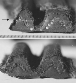
Figure 9.13 Comparison of critical tooth pair (top) with another to show crack path through head of tooth.
The fracture itself showed one main zone of interest, a large curved shape and intersecting a smaller zone at one side, at sharp cusps (Fig. 9.14). The larger zone ran from the base of the belt just above the continuous glass fibre reinforcement to the tip of the tooth, and across the fibre reinforcement within the tooth itself. Numerous ledges running across the width of the fracture surface were visible, suggesting intermittent crack growth over a period of time. The unique nature of the fracture pointed to a fatigue crack growing slowly across the belt until the crack had reached the glass reinforced layer below (Fig. 9.14).

9.3.3 Sequence of events
It was now possible to reconstruct the way failure had occurred. There was probably an initial defect (such as a void or poorly cross-linked rubber) in the zone above the glass filament layer from which a brittle crack grew slowly from first use of the engine. The defect was probably near the lower reinforcing layer, and several severe cracks were seen just above the glass filaments. The worst such defect grew slowly under tension as the belt was pulled by the cogged wheel driven from the engine. The polished appearance of the fibres in the tooth was probably caused by shear and compression as the crack closed when bent around the cogged wheels when driving the road wheel. The loads also developed high frictional forces and considerable heat because when the surface was examined in the SEM, some of the fibres had melted, so local temperatures must have been greater than 257°C. The crack became critical when it reached the glass reinforcing cord because the crack could be seen turning into this layer (lower part of Fig. 9.14). The critical crack then grew suddenly around the belt just above the glass filaments in a single event, so leaving a remnant of rubber remaining where the two crack fronts intersected (Fig. 9.15). It was also likely that other cracks had started at most of the other teeth in a similar position, which in turn suggest that the rubber compound used was defective along most of the circumference of the belt, especially at the junction of the teeth with the glass layer.
When the critical tooth crack reached the glass layer, it grew uncontrollably along the interface, teeth being sheared away successively as the belt met the one or other of the cogged wheels until the whole belt was denuded of teeth and there was no drive transmitted at all to the rear wheel. The debris clogged up the free space within the casing, and the wheel seized. It was clear that the engine drive wheel was resting against one tooth, where the rubber had jammed and formed a wall.
The rear wheel of the scooter seized solid and the vehicle skidded, causing the accident. The drive belt was thus defective from the outset when the bike was new, and the injured user entitled to compensation from the supplier. Such a defective belt should not have been supplied to the bike manufacturer, and other belts from the same batch could have caused similar incidents elsewhere, although none were known at the time of writing. The defective belt could have been spotted during maintenance but was not due for renewal, and thus was missed by mechanics.
Other teeth failures of drive belts include partial loss of teeth, and damaged belts are shown on several websites, with the proliferation of practical blogs and other sites related to car or auto maintenance. Such non-critical defects as loss of teeth can often be detected by changes in the sound emitted by the drive, and are caused by single defects at the base of the teeth rather than the more serious problem discussed above.
9.3.4 Other composite belts
Many different designs of belt are used in critical areas of vehicles, such as cam drive belts, and radiator V-belts, the failure of which can cause major damage to those vehicles when failure occurs. The cam belt is especially important because if it fractures, the timing sequence of the engine is lost and pistons can impact valve heads, so ruining the engine (which must often be replaced). This is why they have to be replaced at very regular intervals (usually at set mileages) irrespective of whether they show external damage or not. The internal defects of the present example demonstrate the wisdom of the policy, because such defects will not be visible externally.
Failures also include radiator fan belts, formerly very common, but with improvements in design and manufacture fortunately much rarer now. As with drive and cam belts, the loads are supported by the spirally wound glass fibre filaments, supported by NBR loaded with carbon black filler. NBR is the preferred elastomer since it is oil-resistant.
9.4 Failure of tyres
The design of car tyres has improved greatly, especially with the advent of the radial type of construction, where a stiff breaker layer beneath the tread effectively improves road-holding and transfers vibrations to the sidewall (3). The inner tube is usually now part of the inside wall, and in compression so that punctures by sharp objects will not have an immediate and devastating effect on the air pressure. The elastomers used have also been carefully selected to provide the best combination of properties for the device. The tread has to have a high coefficient of friction for traction and road-holding, and is usually a blend of NR and SBR, the latter providing high hysteresis, and hence a high frictional coefficient. By contrast, the sidewall must flex easily at high frequencies, so a low hysteresis elastomer such as polybutadiene forms a high proportion of the blend with NR. This means that less heat is produced in the sidewalls when driving than say, SBR. Solid polybutadiene rubber balls are novelty items because they bounce so high, with high rebound resilience, yet who realises that their use in tyre sidewalls helps improve the drive of a car? The inner lining is made from a modified butyl elastomer, such as bromobutyl or chlorobutyl rubber, which has high resistance to the diffusion of air through the layer. The breaker is made either of steel filaments or aramid fibre to provide the needed stiffness, while the beads which hold the tyre to the wheel rims are usually high tensile steel wire.
The rubber tread also has other key functions, such as its role in removing surface water on the road while driving: it is provided by the tread pattern, and if wear reduces the channels of the tread, the tyres may not be able to grip the road effectively. There is strict legislation for tread depth and heavily worn tyres must be scrapped during routine maintenance. Rubber cannot resist sharp objects on the road, such as nails or other metal objects, but punctures are now less frequent owing to the improvement in reinforcing materials such as aramid (which is also widely used in ballistic-resistant materials).
Owing to their complex composite design, all tyres are hand-built, although automated as much as possible, and with strict quality control procedures to check the materials used in their construction. The tyre building machine is a rig designed to accept sheet rubber and other parts to make the final shape before vulcanization, when the rubber parts are cross-linked to give the tyre its stability and integrity. Car tyres are easier to build on such a rig (essentially a rotating drum to which the parts are added in strict sequence) than the larger tyres used on trucks, tractors and other large vehicles. Very large tyres are correspondingly more expensive and so tend to be kept in service for longer, often longer than justified on grounds of safety, as the following case illustrates.
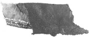
9.4.1 Truck tyre failure
The case was referred after a fatal motorway accident near Doncaster in the winter of 1978/9 following a tyre blow-out on the front wheel of a truck (Fig. 9.16). The tyre (1.22 m in diameter, 36 cm wide and 46 cm rim to rim) showed substantial damage at the crown of the tread, where brittle cracks in the carcass and tread converged (Fig. 9.17). It had been made in 1953 and was 26 years old at the time of the accident, having been on the truck during all of its life. It had been made by Michelin using natural rubber and rayon as the reinforcing fibre for the tyre plies. The shape of the tread indicated that it was designed to work as a tractor rather than a truck tyre, so would be more suitable for moving over mud and earth rather than the smooth tarmac of a high-speed motorway. The condition of the tyre (and the cause of the accident) was central to a civil case before the courts (K James-v-Charles Clarke Ltd).


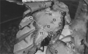
The damage showed a complex series of large cracks in the tread and reinforcing plies (Fig. 9.18). There appeared to be two main cracks running along the axes AB and CD as shown in the figure, which intersected at the probable origin of the damage, shown as O in the picture. But there were many subsidiary cracks, some of which were fresh and part of the final blow-out, others which were filled with dirt and must have preceded the final event.

Closer examination showed that the top of the reinforcing plies had been damaged in several areas at the crown, and are denoted by f1, f2 f3 and f4 in Fig. 9.19. It is likely that such damage (which looked old rather than fresh) had been caused by impact blows to the tyre during its life. Such damage can occur when a vehicle is moving at speed and encounters a hard object such as a kerb or rock in its path. Such impacts have the form of a so-called Hertzian stress profile, where a sharp object presses into the surface and creates compression immediately below the point or zone of impact, but bending further out around the zone. It is the latter which can cause serious damage since the outer parts of the exposed surface will thus be in tension. One immediate effect can be delamination of the tread and carcass since the two layers differ greatly in stiffness, and it is likely that the two layers became separated after the most severe of such impacts.
Damage at and near the origin was severe, and extended well into the substantial ply layers, which comprised 14 layers of unidirectional ply set at angles to one another. Further away on the tread, further evidence of prior damage was visible as ‘chunking’ of the outer parts of the tread (such as shown by ‘ch’ in Fig. 9.18). Shallow abrasion wear was present over most of the tread.
There was no evidence of tyre over- or under-inflation or wheel misalignment, judging by the tread wear. Neither was there any evidence of a manufacturing defect in the structure of the tyre, malicious damage to the tyre exterior, or damage at the rim. There was no indication of heat damage to the rubber, a symptom of heavy use at high vehicle speed (4).
9.4.2 Oxygen and ozone cracking
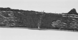
Superficial brittle cracking was present over much of the outer exposed surfaces of the tyre, especially oxygen and ozone cracking, where the rubber had been attacked and degraded by these gases. They were especially evident in the tyre sidewall, the characteristic ‘crazy paving’ of oxygen attack being very clear. At the left can be seen the oriented deep cracks typical of ozone attack on the rubber (Fig. 9.20). Ozone cracks always grow at right angles to the strain in the rubber, and were also seen in the tread grooves at the bases of the prominent bulges in the tread pattern.
The oxidation cracks were about 2.5 mm deep across the sidewall compared with a maximum depth of about 3 mm for the ozone cracks, both being a substantial proportion of the total depth of about 7 mm of the wall (Fig. 9.21). On the other hand, no critical cracks were seen to have grown into the ply layers. The extensive cracking would have been visible to anyone checking the condition of the tyre and its suitability for high speed driving on a motorway.

The tyre was probably composed of natural rubber, which is known to be very susceptible to oxygen and ozone cracking. The finely-divided carbon black filler used in the compound has little effect on cracking.
9.4.3 Sequence of events
From the observed damage, it was possible to distinguish between the recent and earlier damage. Ozone and oxygen cracking was widespread and long standing, but not in itself critical. On the other hand, the traces of old impact damage under the tread showed the kind of deterioration which probably caused the final blowout, especially at the origin (Fig. 9.18). When the tyre was examined for ply damage, it became clear that the fibres of the plies showed frayed ends, while those further away from the origin had been cut cleanly by the rapid growth of the brittle cracks during the blowout (Fig. 9.22).

Following an earlier impact, critical damage had occurred to the plies at the crown of the tyre, and the tread was probably moving freely as a result of delamination between the tread and reinforcement. The tyre pressure was 105 psi, and the plies will have been carrying most of the biaxial stress in the tyre. The individual rayon filaments will have been in tension and subjected to repeated cyclical stresses when the vehicle was driving, causing fatigue cracks to grow steadily through the fibres, which became frayed and fractured at and near the critical damage. Rayon is a synthetic polymer fibre of cellulosic origin and was formerly widely used for reinforcement of rubber.
As the critical crack grew steadily into the carcass, there came a point when the remaining plies could no longer support the inner pressure, and the tyre exploded, The truck was completely destabilized and turned over, crushing the cab and the driver within (Fig. 9.16). Another individual was severely injured. The prior impact damage was hidden under the tread, but the chunking of the tread, which was probably present as a result of impact, should have given warning to the driver of a problem before the accident. The tyre should in any case have been replaced simply from the state of the ozone and oxygen cracking. Such a tyre should never have been fitted to a truck for motorway driving at high speed.
The diamond shape of the fracture (Fig. 9.18) was caused by the alternate orientation of successive plies in the carcass. The hoop stress is resisted by the ply orientation, and so slow fatigue cracks grow along a ply between the fibres, but must cross the fibres of the next ply, producing the frayed edges seen in the picture. When the critical fatigue crack grew explosively, the remaining plies fractured without fraying, as seen in Fig. 9.22.
9.4.4 Modern tyre technology
Cross-ply tyres for cars have now been superseded by radial tyres, with most driving stresses absorbed by the sidewall, so the tread gives a more stable footprint on the road. The materials used are much improved, with speciality elastomer blends for different parts of the structure. Rayon has been replaced by high-tensile nylon fibre or polyester, with aramids frequently used in the tread breaker belt to replace steel cord. The problem of tyre blowout is in any case much reduced nowadays owing to tighter regulation of tyre condition, especially when garages perform routine maintenance. Tread wear past a legal limit ensures that tyres are replaced earlier in their lives, improving car safety (but incidentally increasing the worn tyre mountain, a considerable recycling problem). Many large tyres are still made to a similar design as that which failed, but there are severe restrictions on their use on roads, as legislation has advanced (a fact which is visible on the logos and messages embossed on every tyre sidewall today).
Aircraft tyres are exceptional in that they have to resist great loads when planes take off and land. Many were cross-ply until quite recently when a tyre burst occurred on the Concorde aircraft (Fig. 9.23) taking off from Paris on 25 July 2000. One of the tyres hit a piece of titanium lying on the runway (it had dropped from a previous plane: Fig. 9.24). The tyre burst (Fig. 9.25) and a large chunk of rubber was thrown up. It penetrated the fuel tank in the wing, and the resultant spill and fire caused the plane to crash with everyone aboard killed (5). A new radial tyre was designed as a result, as well as aramid-reinforced fuel tank liners, but they failed to rescue the fleet, which were all scrapped (6). There had been numerous previous instances involving burst tyres on Concorde, and why development of a better tyre was not tasked sooner remains unknown.


Rubber components are of course widely used for other components in vehicles simply because they can mitigate the effects of both high and low frequency vibrations inevitably produced by moving vehicles. One key item in all vehicles is the solid bearings used in the vehicle suspension. In order to attach the bearing to the chassis, they are made by bonding steel plates to the rubber, and often also incorporate steel plates within the structure to modify the acceptable compressive strain without affecting the shear behaviour. But they too can fail, and sometimes with distressing results. Fig. 9.26 shows such an engine bearing which failed suddenly when one of us (PRL) was cornering the car, and resulted in the front wheel assembly falling away. Although the vehicle was halted without an accident, the damage was severe and expensive to rectify. The bearing in the picture failed by shear fatigue at the steel-rubber bond from engine movement, especially during sudden starts or stops. The samples also show some super-ficial ozone cracks, which are not generally a problem with such bearings simply because the rubber blocks are mainly in compression, and the cracks cannot penetrate to the inner parts of the bearing. Small tension loads are expected on outer surfaces, where the cracks form, but are soon halted when they reach the tension zone.

Similar, more complex bearings are widely used in many high performance machines, such as helicopter rotor shaft bearings, where they buffer the high loads during start-up and wind-down of the rotors, and so limit the loads on sensitive metal components, and so prevent fatigue cracks forming and growing (Fig. 9.27).
9.5 Failed Rilsan nylon fuel pipes
The fuel pipes of vehicles are also safety-critical components of all vehicles, and since they are exposed to high engine temperatures, engine oils and fuel, have to be made to a high specification (4). They are frequently made from vulcanized rubber, or sometimes from thermoplastics. The consequences of fracture can be horrendous, because the spray of fuel emitted when the crack finally penetrates the bore is usually quickly ignited in the engine compartment, where electrical sparks are omnipresent. The danger is greater with highly volatile petrol, but diesel fires are not unknown. Diesel spills into the road can cause a separate hazard for the slick quickly forms a slippery layer for other road users. Problems with car fires were encountered on several different car models in the UK in the late 1970s and 80s, and returned with a vengeance in Eire in the 1990s as the result of a failed recall on some models (7).
9.5.1 First encounters
The problem came to our attention in the later 1970s, when car fires were reported on new Ford Cortinas (Mark IV) by insurers, and we were asked to investigate one such incident (although many had been reported. The car involved (Fig. 9.28) only had 10 miles on the clock, and was being delivered to a car dealer. As with many fires, the remains to examine were decidedly daunting owing to the fire damage. The fuel hoses were the subject of immediate attention since the fire appeared to have started somewhere near the fuel pump and the fuel lines running to the device, judging by burning of nearby plastic components such as the air filter cover, battery and fan heater housing. The top of the 12V polypropylene battery case had partly collapsed as a result of the intense heat produced by the burning petrol. There were traces of molten plastic on one of the hoses.

The remains of the burnt petrol hose near the fuel pump showed substantial charring (Fig. 9.29). The original hose carried a textile sheath (at extreme left in the figure) and the main hose from the tank to the pump was severely damaged (centre), showing that it had caught fire quickly, and may have been close to the source of the fire. This sample of pump inlet hose was about 28 cm long, with an ID (internal diameter) of about 8 mm and an OD of 15 mm. By measuring the intact length on another model of the same type, the fragment shown represented all of the hose involved. There were at least three points where penetration of the tube into the bore had occurred, two of which were caused by the fire. However, the third hole was different in shape. It consisted of a longitudinal gash near the pump inlet end, and is also visible in the close-up of Fig. 9.30. The split appears to have run spirally along the tube, and the tube also appears to have possessed a twist when in situ. The rubber used was NBR, which tends to stiffen and harden with intense heat, as several flame tests on new tube showed.


9.5.2 Spider lines
The end of the tube shown in Fig. 9.30 showed a small mark running longitudinally (shown by the upper arrow), which might indicate a problem encountered during extrusion. So-called ‘spider lines’ can be produced where the metal bars which support the die core create a division in the molten polymer. If the rubber was not at the correct process temperature then the lines would be preserved as an incipient split running along the bore of the tube. When pressurized, the split could grow under the inner hoop stress, and soon reach the outer surface, especially if the rubber had been over-cured so that it was stiff and brittle. It was concluded that this is what had most likely happened and since a large length of tubing might have been made originally, there would be a problem on many new models, as indeed, a press item showed shortly after our report had been produced. The Daily Telegraph of 10 June 1981 reported that:
An urgent investigation is being carried out by Ford engineers after 12 cases of fire breaking out under the bonnet of Cortina cars less than 18 months old. The fires which start when cars are at rest after a long high-speed run, are thought to be due to a new air filter system which becomes overheated causing molten plastic to drop onto the exhaust manifolds, where it catches fire. The Mark IV Cortina has been in production for about four years and it could be a freak occurrence affecting recently built models, a spokesman added.
The report may correctly reflect the statement made by Ford, but seems to confuse cause and effect: the molten plastic was likely caused by the fire from the leaking fuel pipe and not vice versa. The comment about a freak incident betrays a lack of analysis of the problem, with the fuel pipes the most likely source of the problem. In response to our report, Ford suggested that vandalism with a knife could cause the problem, but there was little evidence of a cut in the braid, let alone the tube of the car we examined. Under a standard then applicable to hose, a pressure test was required for petrol lines of at least 50 psi, but whether or not it had been carried out was unknown. The line itself was under a much smaller pressure, but enough in their tests to produce a leak rate of 10 ml/min: not great but enough to start a fire with further fuel siphoning through from the tank.
A recall was carried out, and the repairs were very simple and of low cost: simply replace the affected lines with high quality hose. The faulty tubes had an inner weld line (similar to those found in some faulty injection moulded plastics) that would be impossible to detect without removing the lines and cutting them up to view the inner bores, a good example of a latent defect. It is interesting to note that textile braided tubing of the kind used on the Cortina offers no protection against ozone gas initially, but when in use for some time in a car, becomes soaked in grease and oil, which does form a barrier against the gas. But the best remedy is to use an ozone-resistant rubber such as EPDM or add an anti-ozonant to the compound.
9.5.3 Sir John Gielgud
However, there are other causes of fuel line failure, which can also be dif-ficult to detect by visual examination alone, especially in textile covered rubber hose. The problem is ozone cracking, as already discussed elsewhere. And the problem had been encountered in another new model: the Fiat Mirafiori. In fact we had reported on the problem a few months before the Cortina problem. The car involved was bought on 31 January, 1978 with a mileage of 12 342, and had a mileage of 45 051 at the time of the incident, so was not brand new like the Cortinas.
The car fire happened rather dramatically, as appropriate to one of Britain’s most distinguished thespians, Sir John Gielgud. He was being chauffeured down the Chelsea embankment at 9.30 am on 18 July, 1981, and while halted at the traffic lights on the Chelsea Bridge road, the chauffeur noticed smoke rising from below the bonnet. With the aid of an extinguisher he managed to control the flames until the London Fire Brigade arrived to douse them completely.
The damage was extensive as shown in Fig. 9.31, but it was possible to locate the source of the fire by examining the nature and direction of flame damaged components. Analysis of unattractive and often daunting remains lies at the heart of all forensic work, and often leads on to the cause or causes of the problem, which is the basic motive for all investigators. So what did the remains show? The first task was to identify the major damage to visible parts, such as the large radiator hose in left foreground (A), which has almost burnt through near the engine block near the centre of the picture. Just above can be seen the charred remains of the radiator expansion hose next to the radiator filling cap, although an adjacent pipe at B is scarcely affected at all. It was the burnt remains of the fuel hoses (at C) which suggested where the fire had started. The remains consisted of a large diameter rubber tube and a shorter length of narrow diameter thermoplastic tube next to it.

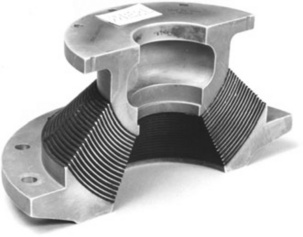
A narrow tube in good condition lay at D and one vane of the radiator had melted (not shown in the picture but located at E). One of the plastic covered leads to the sparking plugs (F) had been destroyed: the front lead near G in the picture, together with surface discolouration to the distributor cap. There was also some minor damage to the air intake of the heating system at H, and the battery had suffered some charring and partial melting at J. Further information from the repairer of replacement parts supplied showed that minor damage had also occurred to the fan belt, expansion tank, radiator grille, washer bottle and bonnet. The flames had clearly risen up from the source and been deflected down wards by the bonnet so as to affect more distant parts of the compartment. The remains showed that a liquid spill must have occurred because various parts (such as the distributor cap) below the assumed source of the flames had suffered flame damage. The pattern of damage was of intense heat near to the metal oil filler cap on the engine block, judging by the severe hole burnt in the radiator hose near a metal U-clip holding several pipes. A close-up of this clip (Fig. 9.32) on an intact model showed that it originally held two types of fuel hose. The pattern of damage indicated a flow of flaming petrol from a point very close to the clip, from one or other or indeed both of the fuel lines passing through the clip.

9.5.4 Fiat fuel lines
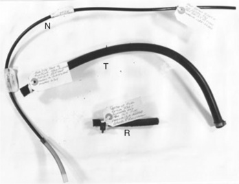
The fuel pipes from several Mirafiori saloons of similar age to Gielgud’s car were supplied by the insurer for detailed examination, and are shown in Fig. 9.33. The narrow long tube (N) is the fuel return pipe and was taken from a Mirafiori saloon with 21 345 miles on the odometer, as was the plain rubber tank to fuel pump sample (T). The small sheathed sample was taken from another Mirafiori of similar mileage (R).
The thermoplastic tube showed one zone at which the surface had been abraded by contact with the sharp metal edge of the U-clip (marked by the paper label at left (in Fig. 9.34) while the longer of the rubber tubes (T) showed deep ozone cracks (similar to those in Fig. 9.35). The external surface of the rubber was unprotected by any textile sheath, unlike the rubber fuel lines of the Cortinas. It exhibited deep ozone cracks oriented at right angles to its length, in such a way as to suggest that the cracks had formed when the tube was bent to a low radius (as one might expect when in place in the engine compartment). The form of such cracks is shown schematically in Fig. 9.36. Closer inspection also showed a smaller number of longitudinal cracks, rather surprisingly, on the underside or compressive part of the tube. The cracks were measured using a depth gauge (a stiff wire) and analyzed, the distributions for depth and length respectively being shown in Fig. 9.37. The deepest crack was at about 2.5 mm, compared with tube dimensions ID of 5 mm and OD of 16 mm with a wall thickness of 4.5 mm. The worst crack was thus over half way through the wall.
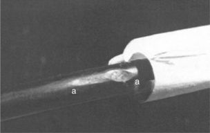

Figure 9.35 Ozone cracks in NBR rubber fuel hose: the hose has been bent to open the cracks. Crack length (mm)


Figure 9.37 Histogram of ozone cracks in smooth rubber fuel pipe from Mirafiori saloon: crack depth at top and crack length at bottom. Vertical scale: number of cracks.
The rubber was identified from simple swelling measurements, where cut sections of hose are dipped into several different organic solvents: the degree of swelling shows the type of elastomer present. Identification can also be achieved somewhat faster and more exactly using ATR spectros-copy by pressing a free surface against a selenium single crystal and obtaining the absorption spectrum on an FTIR spectrometer.
Ozone gas is produced near electrical circuits, especially where either sparking or silent discharge of current occurs. Rubbers with double bonds in their chains (NR, SBR, NBR especially) are susceptible to cracking because the gas attacks the bonds and cleaves them very quickly. Only very low gas concentrations are needed (parts per billion in air), and so high concentrations of the gas may be expected near to the electrical distribution system (Fig. 9.32). So if the damage was produced by about 20 000 miles car usage, then failure (deepest crack reaches tube bore) would be expected between 30 000 and 40 000 miles, assuming constant ozone production.
The plastic tube was identified as Rilsan nylon from its melting point of about 176–180°C, with a density of 1.04 g/cc using a standard sample for comparison. It is a thermoplastic polymer (8) composed of nylon 11 chains plus filler (probably carbon black at low level). The two abrasion zones (Fig. 9.34) were caused by direct contact between the pipe and the sharp edge of the U-clip and the inevitable vibrations from engine movement during driving. The damage (at right in the figure) was measured as 0.5 mm deep in a wall 1 mm thick, so was also significant. The zone was an ellipsoid with major and minor axes measuring 5 mm by 2.5 mm, so difficult to see unless the tube was removed for inspection. The engine temperature after some time running (so at equilibrium) was measured directly with a contact thermocouple at about 70°C, so the U-clip would have been at a similar temperature. Since the damage had penetrated about half the wall thickness, it would fail after the damage had penetrated the tank-pump line.
Both kinds of defect represented a considerable risk for users of well-travelled cars such as that used by Gielgud. He clearly travelled a great deal, acting at different theatres around the country, and since the mileage at the time of the accident was about 45 000, it compared with the estimates made from the younger samples (Fig. 9.33). And it also appeared from that analysis that ozone cracking was marginally more likely than abrasion to have caused the fire in Chelsea. The samples from Gielgud’s car were unfortunately much more seriously damaged than those from the Cortina, so were of little help in the final analysis.
It was a situation which could only be resolved by a recall by the manufacturer, although the Fiat Motor Company were initially resistant to the claim, as the following timeline shows:
1. 18 July 1978 Gielgud car fire
2. 8 August 1978 Insurer’s motor engineer indicates petrol rather than electrical fire
3. 21 August 1978 Car repairs approved
4. 29 August 1978 Request to us to investigate
5. 8 Sept 1978 Our report identifies ozone cracking and recommends replacement of all rubber pipes
6. 14 December 1978 Request note to Fiat from insurers asking for payment
7. 25 January 1979 Fiat refuses payment
8. 26 February 1979 Fiat requests proof of claim
9. 12 July 1979 Fiat recalls Mirafiori cars for rubber tubes susceptible to ozone cracking
However, the recall eventually went ahead, although the problem with the Rilsan tubes remained. Perhaps Fiat advised mechanics to examine and replace damaged tubes, or alternatively chamfered the corners of the U-clip. Both were simple faults easy to remedy and cheap to rectify. The only surprising feature of the case was why such elementary design mistakes were made in the first place.
9.5.5 A car fire in Ireland
Unbeknown to innocent drivers in Eire, many were happily driving around in the 1980s in Mirafioris which were in a dangerous condition. The Fiat Company in Ireland had not carried out a recall, so putting many drivers at risk of immolation. All this and more emerged from a preliminary trial at the Supreme Court in Dublin in the 1990s. But how did we become involved? The story is rather tortuous, but easy to understand. A case of negligence had been lodged in Eire after a car accident on 23 June 1988.
That particular car, a Mirafiori saloon, suddenly burst into fire and severely injured two young children. Mrs Murphy, driving the car in Co Carlow, had been returning home from shopping with her two children strapped in the back seat. She stopped in the drive of her house, and removed the ignition key because the house key was attached. She went to her front door and after opening it, went inside to put the kettle on and then turned back to collect the children. As she left the house, she saw smoke in the sky and turning the corner of the house, saw smoke billowing from the partly open sunroof of the car. The interior was full of smoke and she could see an orange glow between the front seats. She fainted, but her sister-in-law pulled the children out, although they both suffered severe and extensive burns from exposure to the flames. She estimated later that she had been gone from the car for less than a minute. The fire seemed to have started in the car interior rather than under the bonnet, so what caused the problem?
The car had been bought second-hand in 1987 with 29 000 miles on the clock, and it had covered about 35 000 miles at the time of the accident. It had received a full service in May 1988. The burnt-out car was examined by several investigators, some of whom created irreparable damage by removing various electrical parts, a shocking revelation given the importance of primary evidence. However, much of the evidence which might have yielded a clue to the origin had been consumed by the fire (Fig. 9.38). One possible cause lay in the electrical circuitry from which a fire could have been started by a short-circuit. According to the investigator who contacted us, short-circuit fires are a common problem in many cars, owing to the nature of car wiring using the chassis as the common earth. Many cars such as the Mirafiori, had live circuits even though the ignition was switched off. Some permanently live circuits had no fuse protection at all. There were known problems with the car heater on the Mirafiori, and one investigator concluded that this was the most likely cause of the fire which gutted the vehicle and injured the children. A short circuit in this component led to ignition and then fire in the dashboard.

However, the fuel pipe from the pump in the engine compartment ran through the interior to the tank at the rear (Fig. 9.39). It is possible that it became abraded by contact with a sharp metal edge and leaked, followed by fuel ignition. Where the pipes passed near the doors, for example, could be a zone where repeated vibration could initiate abrasion. So an alternative scenario to an electrical fault involved a liquid leak occurring before the driver stopped, with the vapour ignited by a static electricity charge, a possibility we raised given our experience of the earlier fires. Such static charges are common in dry weather when a motorist steps out because the car is insulated by the tyres, and when the driver touches the ground, a spark will often leap between the car’s metallic body and the driver. Whatever the source of ignition, the interior used many highly flammable plastics (such as polystyrene and polyurethane) which helped fuel the conflagration.

9.5.6 Murphy infants-v-Fiat spa
The Irish Times report of the trial on 12 October 1994 summarized earlier proceedings of the case:
… the insurers of the father’s car, NEW PMPA agreed to pay substantial damages totalling £815 000 … after the then President of the High Court, now Chief Justice, Mr Justice Hamilton, had approved the settlement. This was on the basis that the children had to be compensated by somebody, and should be spared the delays of the legal process.
Whatever the precise cause, the case which came before the court related to the discovery of documents from Fiat spa in Italy, and their knowledge of the Mirafiori problems. Fiat had produced little in the way of documentation, and specifically the fuel line recall held in the UK. Indeed, our own work had only been found by the investigators when they approached the original insurers (Guardian Royal Exchange) who held a reference to our work, but nothing else. Our original report had been removed from their archive since such reports are routinely destroyed after six years, although its existence was recorded in their archive.
The investigators approached us and we fortunately not only held the original report but also several samples, and all related documents such as correspondence and the recall notice itself. We provided a copy of the report to the Plaintiff’s solicitor, who then supplied it in the form of an affidavit to the Supreme Court as evidence of a known prior problem with the cars in the UK. The case against Fiat was argued by James Nugent SC, then Attorney-General in the Irish Government, a sign of the seriousness of the case. He advocated a so-called ‘striking-out’ motion of any defence Fiat proposed to the charge of negligence in the case of the state of Mrs Murphy’s Mirafiori car owing to their refusal to supply documents regarding the fuel line and other known problems of the model. It was a draconian action proposed by Nugent, which meant that, if approved by the court, that Fiat would have no defence against the Murphy children and would inevitably lose their case when it came to full trial.
As the author of the original report, one of us (PRL) was invited over to attend the hearing in the Supreme Court. While flying to Dublin, I was seated near some passengers of Italian origin speaking in English with a solicitor. I thought nothing of it until when watching the court proceedings, I recognised one of the Italians when he appeared on the witness stand, and who turned out to be their head of legal services, a Mr Antonio Scognamiglio. I warned our counsel that the translator was not needed, since the witness could speak and understand English. The witness benefited of course, because he then had twice the time to think of an answer and respond! However, his answers were very evasive, as were those of other Fiat witnesses.
Judgment in the case was given the following year by Judge Johnson, and he was quoted in the Irish Times article published on 4 March 1995. He said:
the Fiat companies had failed to comply with the discovery orders because of their failure to contact their sources, and he still did not know what documents had been or were in their possession relating to fires which occurred in the Fiat model Mirafiori between January 1st, 1979 and June 23rd, 1988, and reported to the Fiat parent company.
Counsel for the parents, the Murphys, claimed in court that Fiat were engaged in a deliberate and sustained attempt to conceal from the court details of hazards in Mirafiori cars in the 1980s. Further, the paper said, the judge paid tribute to the ‘extraordinary energy’ of Francis X Burke (solicitor to the Murphys) that the failings of Fiat had come to light. He also said that the:
two witnesses for the Italian Fiat company demonstrated to him in the witness box an elusiveness, an unwillingness to be pinned down as to what documents precisely they might or might not have had or what they might get when enquiries were made…. He found the attitude taken by Fiat … towards the recall campaign of Fiat Mirafiori cars to be nothing short of contumely.
The judge went on to strike out the Fiat defence. However, an appeal to the Supreme court was made by Fiat in view of the rather draconian judgment (which effectively deprived Fiat of any defence to the claim). The appeal was successful, but Fiat agreed to a settlement with the insurers. However, there was a sting in the tail for the company.
9.5.7 Other Mirafiori fires
The trial opened up the issue of fires not just elsewhere in Ireland but also in the USA. If there had been problems in 1988 with just one Mirafiori, had there been any earlier cases, as one might expect given such a serious design flaw in the car? There had indeed been several fires in Mirafiori cars, one of which resulted in the death of a solicitor. The accident happened on 1 September 1977 in Kilrush, Co Clare. Damage was so extensive that iden-tification of the victim, Daniel Chambers, was only possible by the survival of a ring and a sandal buckle which he was wearing at the time of the tragic accident. The car was a burnt-out shell although the police investigation concluded that the car caught fire while being driven, and then went out of control. The car had been bought brand new only 11 months prior to the accident, and must have had a low but unknown mileage. Correspondence at the time referred to other fires in Mirafiori saloons. The accident had occurred well before the Gielgud fire, and could well have been caused by the faulty fuel lines, whether by ozone cracking or abrasion of the Rilsan pipe.
But further investigations by Burke revealed many more fires in the same model, needless to say, without the help of Fiat. No less than seventeen unexplained fires were known to have occurred on the model in Eire by the time of the trial, seven of which dated to the late 1970s with ten in the 1980s. A fire had even broken out when a motoring correspondent had been test driving a Mirafiori in October 1978. Unfortunately, few had been investigated seriously, but heater fan switches or fuel line problems were suspected in many of them.
Further enquiries in the USA (where the model was known as the Brava) revealed a shocking state of affairs. There had been several deaths in Brava models, including the death of Dick Treon in Arizona in 1976 due to a ‘defective hose’. Several recalls had been initiated by the NHTSA, including the heater switches, drive shafts, and finally in 1978, fuel lines. In 1979, a Department of Transportation inquiry was launched to examine under-hood fires in several different Fiat models as a result of 22 reports of fires which had probably been caused by: ‘fuel hose deterioration, fuel leaking from faulty carburettor and canister problems and electrical wiring problems.’
At the time, Fiat denied even the existence of a problem. Despite the various recalls in the USA, accidents continued (as in Eire). A number of crashes involving Bravas resulted in fires: not always an unexpected outcome, but if the fuel supply system was known to be flawed, it did not take any leap of imagination to realize that the impact loads developed in crashes could well cause the failure of weak parts (such as the cracked or abraded fuel lines). In a survey by the University of Michigan carried out in 1995, they examined the NHTSA archives, and found no less than 161 deaths in Fiats from all causes between the early and mid 1980s. Of these, 58 were fire-related and included six Bravas. The publicity in Dublin regarding the case meant that old cases of Mirafiori fire casualties were re-opened, and increased compensation for the injured persons.
9.5.8 Global markets
The case highlights the way a major manufacturer mis-handled a major product liability problem of one of their new designs in the 1970s, and thereby left a trail of injured drivers and worse. The problem could have been solved at the outset by correctly specifying the fuel pipe design, construction and material to avoid what was, and still is a well-known failure mode of many elastomers. The abrasion resistance of Rilsan tubing is also low, especially at engine temperatures. Fiat had a second chance to correct their original errors when the first accidents were reported shortly after launch of the Mirafiori/Brava, but their reporting procedures appear to have been very poor. Here is what Scognamiglio had to say when asked about the Gielgud incident in the 1994 trial in Dublin:
Q. When you saw the papers that there was reference to a fire in the United Kingdom on Chelsea Bridge, a vehicle, the property of Sir John Gielgud, did you write to the importer who controlled the market?
A. I did not write to the importer of that market but I made a phone call.
A. I called someone in the Technical Service Department but I cannot recall the name because I didn’t know this person.
JUDGE: The Technical Service department in England or Italy?
A. In England. He confirmed the name which I believe this person … is the name in the Affidavit. This person just confirmed to have seen this car and denied that there was any problem, any manufacturer’s liability ….
Q. But a claim had been made, a complaint about the car had been made after the fire even though this person thought it was invalid, is that correct?
A. I did not investigate any further, I was only curious to find out what had happened.
Q. Did you ask him if there were any documents extant in relation to a complaint from or on behalf of Sir John Gielgud?
So the head of product liability at Fiat in Italy did not follow up information which was important in pinpointing the design fault in cars for which he was ultimately responsible, especially our report of why such failures were happening at all. The company would pay heavily for that error, but the heavier burden would fall on many unfortunate drivers and their passengers. Production of the car ceased in 1985, and the same witness went on to state that all records were destroyed at that time, despite the fact that many second hand Mirafiori’s were being driven around the world. Even the insurers kept a note about a report, even if they didn’t preserve the report itself. Such negligence by the manufacturer has an unhappy way of repeating itself, as knowledge is lost about design defects and potential failure modes. It was, however, fortunate that one investigator kept intact records to support the Plaintiff’s case.
It is not necessary to wait for the first fatality, because early failures can give a fair warning of what might occur later, so giving time for a recall and change of design. However, it does mean that any early incident is thoroughly investigated and analyzed. It is poor practice to deny that a problem exists when there is clear evidence of product failure, especially if similar incidents occur across several different countries. It is more likely than not that failures may be under-reported, as, for example, when a garage might spot a cracked fuel line and replace it before any incident occurs at all.
9.5.9 Fires in tunnels
The effects of vehicle fires are serious enough when they occur in the open, but in tunnels, they are much more dangerous. Truck fires within the Channel Tunnel in 1996 and September 2008 created great disruption for users as well as structural damage to the tunnel lining, despite being contained. Not only are high temperatures generated but the smoke and gases generated are life-threatening in the confined space. Increasing the ventilation just increases the intensity of the fire, so is counter-productive. Although the fires were successfully contained, the fire which occurred in the Gotthard road tunnel on Friday 24 October 2001 spread rapidly and killed 11 people trapped there (9). They were killed by gas and smoke inhalation, with carbon monoxide the main culprit. The fire started on a truck, and spread rapidly to engulf surrounding vehicles, a problem which frequently occurs in vehicle pile-ups on motorways.
It is clear that more improvements in vehicle design are essential if further accidents are to be avoided, electrical systems and fuel systems being a top priority. The costs of implementing only modest changes can often be minimal. Thus changing fuel lines from commodity rubbers like NBR to ozone and fire-resistant elastomers like Viton are small compared with the damage than can occur from fires. But even armoured lines can be at risk if the matrix rubber remains susceptible to ozone attack, as a recent case involving fires on aircraft haulage vehicles at Heathrow showed. Ozone cracking had developed over many months, and the cracks had penetrated through the inner metal reinforcement mesh until they reached the bore. The subsequent fuel leak caused several separate fires in a number of such tractors before the basic cause was discovered.
9.6 Stress corrosion cracking of nylon connectors
There are other failure modes found beneath the bonnet, and we have discussed one of them in detail previously (10, 11), where a nylon connector in a Rilsan diesel fuel line fractured by stress corrosion cracking or SCC. The failure eventually caused an extensive leak of diesel fuel, which fell into the roadway rather than igniting, but the spillage was almost as devastating as a fire because diesel fuel will form a treacherous surface after a few minutes. The lighter fractions of hydrocarbon evaporate to leave a slick of the higher fractions of fuel, which comprises a thick and viscous oil. The spillage is almost invisible to oncoming drivers, who can lose their steering when the front wheels hit the slick. The effect is of similar danger as ‘black ice’ where a patch of invisible ice occurs on a road, ready to destabilize moving traffic. Motor cycles are especially at risk, but so are cars, because when they skid they can collide with other vehicles. Drivers will be aware of the problem of black ice because low temperatures give some warning of the problem, and particular spots on roads are particularly risky, such as bridge crossings, where ice formation occurs earlier than elsewhere owing to the rapid cooling of roads on bridges (cooled from above and below).
The failure of the diesel return tube occurred in 1997 and led to three accidents, the most serious of which involved a car which skidded on the patch of diesel, and collided with a lorry in the opposite lane. The driver was seriously injured and claimed damages from the driver of the recovery vehicle responsible for the diesel leak (Fig. 9.40). The police quickly traced the vehicle with the broken fuel pipe since they followed the trail of diesel to a local golf course. Ironically, it turned out to be a break-down vehicle from a local garage. They retrieved the fractured fuel return pipe (Fig. 9.41) and organized repairs. The Forensic Science Service in Strathclyde concluded that the fuel pipe had been cut by a knife, so vandalism was suspected. However, the position of the connector was almost completely inaccessible and why cut the connector when the Rilsan fuel pipe itself was much more accessible?


Figure 9.41 Fractured nylon connector (right) compared with intact return tube (left). Arrows show abrasion damage.
The fracture surface (Fig. 9.42) did not show the characteristic parallel marks caused by defects in the edge of a blade, but it did show striations similar to those seen on fatigue fractures. The edge of the surface (lower part in the figure) did show some damage, and X-ray analysis in the ESEM showed traces of sulphur. Since the junction in the fuel pipe was directly below the lead-acid battery, it was inferred that a small leak of battery acid initiated degradation at the corner of the joint. Nylon is especially sensitive to sulphuric acid, a strong acid which will hydrolyze it and other polymers rapidly. A crack started as damage progressed from the outer surface into the bulk, perhaps assisted by the internal strains produced by injection moulding. When tested separately, nylon degraded fast and then cracked, while the Rilsan or nylon 12 line proved totally resistant.

The small movements of the fuel line when the truck was being driven were probably enough to induce small incremental growth steps in the fracture, as shown by the scanning electron micrograph of Fig. 9.43, until the tube finally parted. Leaking of the fuel will have occurred as soon as the crack penetrated the bore, but the rate will have been low. However, as the cracks grew, the rate will have increased (Fig. 9.44). The question of how fast the rate increased was relevant, and it was possible to suggest that the major crack arrest points occurred when the engine was turned off. It was reasonable to suggest that this occurred daily, since many diesel work vehicles are left running for the whole day. Since there were seven such major arrests in the fracture surface, it suggested that the cracks had grown over about seven days, giving the driver ample opportunity to discover and rectify the leak before final failure. As a result, the insurers paid the injured motorist substantial compensation for her serious and at one point, life-threatening injuries.


9.7 Conclusions
This chapter has highlighted cases of failure of car components which have caused accidents and personal injury ranging from poorly designed tail-packs for motorcyclists, badly made drive belts to the problem of old tyres and fuel line systems in new cars. The accidents which resulted from these components were avoidable, and should have been addressed either by the manufacturers and designers in the cases of the tailpack, drive belt and fuel lines. The drivers should have taken care in ensuring their vehicle was roadworthy in the cases of the tyre and the leaking fuel line on the recovery vehicle.
And it is not as if such cases have not occurred before. The design of the Ford Pinto in rear vehicle shunts showed that the petrol tank could be pierced by sharp parts of the transmission system, resulting in vehicle fires, a problem that resulted in several law suits in the USA (12). Ralph Nader described in his book Unsafe at Any Speed published as long ago as 1965 the problems of poor safety design in cars (13), a general problem which has been addressed by most manufacturers in developing safer components such as laminated windscreens, air bags, collapsible steering wheels, radial tyres and the crash-resistant cell for the passenger compartment. The external features of cars, such as wing mirrors, radiator caps and front bumpers have also been redesigned to mitigate injuries to pedestrians in collisions. Safety engineering indeed has become a selling point for manufacturers, although there is still great room for further progress. For example, drivers tend to travel too close to one another, especially during high-speed driving on motorways. The behaviour can lead to the problem of catastrophic pile-ups during adverse weather (fog, heavy rain, road ice, etc.). A simple radar detector fitted to the fronts of cars would help warn drivers of their danger, but the device has yet to be adopted. The growing use of computer control systems for engine management and other basic functions may encourage manufacturers to adopt more extensive safety warning systems, however. One feature of the new ways of controlling cars is the use of sensors buried in the fuel system, for example.
Another way in which such technology could be adopted to improve safety would be to have automatic pressure loss sensors to tyres, a device which would help motorists address the problem of under-inflated tyres, for example. Tyre damage increases greatly in such a condition, and increases the chances of a blow-out. In addition, fuel economy falls rapidly because more energy is expended in tyre deformation when tyres are under-inflated. Run-flat tyres have been developed by many tyre makers, but have yet to be adopted widely across the industry, perhaps owing to their expense. There is no doubt that the materials of construction have improved greatly, so that oxygen and ozone cracking are now rarely seen in tyre sidewalls, for example.
Fuel lines continue to be a concern simply because any failure could cause leaks which can in turn cause fires or explosions, or a hazard to other road users in the case of diesel leaks onto the roadway. The case of the tractor fuel lines is a case in point, where greater attention to the problem of ozone cracking could have prevented a series of fires on vehicles close to airplanes.
The investigation of vehicle accidents is almost a separate discipline in forensic engineering, such is the sheer number of fatalities and injuries from use of our roads (14). It uses methods such as dynamic analysis, trace evidence examination and materials testing to determine the precise cause or causes of accidents to help resolve personal injury actions. The design lessons have frequently been implemented by manufacturers to improve car safety, although the fall in fatalities over the last two decades also reflects the changes in public attitudes and legislative action to control user behaviour.
9.8 References
(1) National statistics available at www.statisics.gov.uk.
(2) McIntosh, D.H. HMSO (Met Office,) under ‘Beaufort scale’. Meteorological Glossary. 1963.
(3) Naunton, W.J.S., The Applied Science of Rubber, 1961. [Edward Arnold].
(4) BS ISO 19013-1:2005 Rubber hoses and tubing for fuel circuits for internal combustion engines. (Diesel fuels); BS ISO 19013-2:2005 Rubber hoses and tubing for fuel circuits for internal combustion engines (Gasoline fuels); there are many other standards for all types of hose, including hydraulic hose in a wide variety of industries supplied by British Standards.
(5) BEA Final report on the accident that happened to the Concorde registered F-BTSC operated by Air France on 25 July 2000 at Gonesse (France). 2004 available for download at: http://www.bea-fr.org/docspa/2000/f-sc000725a/htm/f-sc000725a.html
(6) Information on the events of the accident and the consequences available at: http://en.wikipedia.org/wiki/Air_France_Flight_4590.
(7) Discussed briefly in Lewis, Peter Rhys, Reynolds, Ken and Gagg, Colin. In: Forensic Materials Engineering: Case Studies. CRC Press; 2003:194. [ff.].
(8) Brydson, J. Plastics Materials, 7th edn. Butterworth, 1999.
(9) Information available at: http://en.wikipedia.org/wiki/Gotthard_Road_Tunnel.
Lewis, Peter, Rhys, Reynolds, Ken, Gagg, Colin. Forensic Materials Engineering: Case Studies. CRC Press, 2003; 199. [ff].
(11) Lewis, Peter R., Hainsworth, S. Fuel Line Failure from stress corrosion cracking. Engineering Failure Analysis. 2006; 13:946–962.
(12) Such as the case of Grimshaw-v-Ford Motor Co, 1981. available at: http://online.ceb.com/calcases/CA3/119CA3d757.htm
(13) Nader, R. Unsafe at Any Speed: The Designed-In Dangers of The American Automobile. New York: Grossman Publishers; 1965.
(14) Sherman, R.M.Point of Impact: Case Studies of Forensic Engineering in Personal Injury Lawsuits. Lawyers and Judges Publishing Co Inc, 2001.