
Tools and ladders
8.1 Introduction
Manufacturing in Western countries has changed dramatically in the last two decades, as product designers have switched to developing nations, especially in the Far East such as China, Malaysia, Tawain and South Korea. Labour costs are much lower there, and so it is possible to manufacture components and even complete products at much lower cost than in the West. Much of the process equipment is new, so exploits the latest advances in technology, such as computer control of operation and so on. However, experience with some polymers seemed to be poor as new products emerged, and there were a number of failures on imported goods, such as cheap knives and electric plugs. If the handle on a knife fails, there is a chance that the user will be injured since their hand will be close to a very sharp blade. Power tools offer extra risks because they may use high speed parts to achieve their function: angle grinders, for example, use a very high speed abrasive disc and if the handle fails suddenly, the user is put at serious risk of severe injury. Both the design and material used must take account of the high stresses to which small and power tools can be subjected when in use. Security guards for gas cylinders is an innovative way in which the toughness of thermoplastics like polypropylene can be exploited, but if manufacture produces weaknesses such as weld lines, then the product can fracture prematurely and have the opposite effect to that intended.
The expansion of the injection moulding industry has led to many new designs in thermoplastic of traditional products like chairs, tables and other furniture. But wood is a composite and normally tough material, and many apparently tough polymers can be embrittled through poor choice of grade, designs which incorporate stress concentrators, or simply by poor manufacture. Chairs in particular can be subjected to high loads from users, and sudden failure can cause serious personal injury. But polymers are also widely used in metal products where their failure can also cause sudden collapse. Ladders are especially safety-critical products, where failure of rubber feet or tips can propel the user onto the ground. Similar comments apply to stepladders, loft ladders and steps used for swimming pools.
8.2 Failure of polypropylene hobby knives
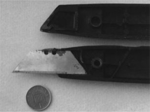
The Stanley knife has become so widely used as to become something of a design icon, yet large numbers of plastic handled knives which accept the same sharp blade have been designed and are widely used. Some of the first designs to be imported, however, suffered rapid failure owing to the poor way in which the handles were designed, and the users suffered cuts, sometimes of depth and severity (knife on left in Fig. 8.1). A workman was cutting the backing from wooden floor tiles, and while using a plastic hobby knife, cut into his right index finger, severing a nerve and an artery. The depth of the cut was great, and despite emergency surgery, the individual continued to have problems with using his right hand. The accident happened in 1981, and a claim was made against the insurers of the sellers of the knife. At the time we reported to the insurers in 1983, the case had advanced to court action.

8.2.1 Accident reconstruction
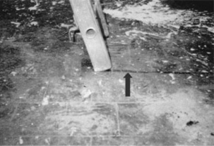
Although the failed knife had not been sent for inspection, an exactly similar design was sent and proved distinctly dangerous. Pushing the blunt side of the blade against a desktop caused the blade to rotate into the plastic casing, but fortunately without cutting the user’s fingers or hands (Fig. 8.2). The problem was caused by using a relatively soft plastic to hold the blade in position, as the innards of the product showed (Fig. 8.3). The metal blade was held in place against rotation by just two pieces of soft plastic, a small knob which mated with a U-shaped depression in the side of the blade, and a strip of plastic of the body acting against the sharp edge of the blade. They were clearly insufficient to prevent the blade turning into the fingers of users, especially if the tool was held in a power grip (1,2) (Fig. 8.4). The material used was a polypropylene copolymer with ethylene, the content being 4 to 10 weight %, making the plastic more flexible than a homopolymer by suppressing crystallinity. The parts were all injection moulded, and the product was of Italian origin.


The amount of force needed to rotate the blade in its plastic handle was measured using a hydraulic tensometer, a task needing some care in positioning the knife so that an accurate reading of the compressive load could be found. A load of about 3 kg was found to cause rapid rotation of the blade into a position where it could do serious damage. Such a load is easily achieved by the hand pressing down, and so such an accident was entirely feasible. A Stanley knife tested under the same conditions showed that failure occurred at about 35 kgf, well over ten times the failure force used in the failed knife. A survey of similar knives available for sale showed their designs to be much superior, either using stiffer plastics or having a small metal insert to prevent rotation of the blade into the hand of the user. The medical evidence showed that the injuries to his right hand were consistent with the power grip of Fig. 8.4. Although the original failed knife was not available for inspection, photographs showed that the damage was very similar to that found in the tests on new knives. The final question was how he came to put the blade into compression, a not unreasonable point, since the product is designed to be used so that load acts in the opposite direction to that in which it failed. The answer comes from seeing how such knives are used in service, the sharp point often being used to make a deep hole, when, for example, first making a cut into a tough material like a floor tile. This is when the tip can rotate in the direction in which it failed, as pressure is applied to the tip, sometimes acting against the blunt side of the blade. The workman was compensated for his injuries.
8.3 Failure of polystyrene components in hobby knives
One might have expected that such knives would be removed from the market so as to prevent further injuries. But not so, because yet another hand injury was caused in the early 1990s by a not dissimilar design, but this time it was stamped very clearly with the logo ‘Made in England’. The product had been used to cut plastic trim at the time, and the user claimed that the blade suddenly rotated and cut deep into his index finger. Since the enquiry came from his solicitor, the user wanted an objective explanation of the failure so as to sue the supplier.
So what had happened in the accident? In his witness statement, the user, a fisherman by trade, said that he was cutting the trim when the blade flew out, cutting him slightly. He put the blade back in and tightened the central screw hard, but it flew out again, rotating upwards, and this time it made a deep gash in his right index finger, cutting down to the bone. His account was supported by two policemen who happened to be present. The medical report showed that he had severed a nerve, and he suffered considerable distress since his hands were a vital part of his work. He had been off work for many weeks as a result of the damage to his hand, much like the previous case.
8.3.1 Knife inspection
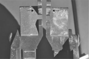
This time, the failed knife was available for direct examination (Fig. 8.5). The two matched mouldings which formed the case were attached by a single screw, as the user had described. Unlike the Stanley knife, however, there was no means to withdraw the blade into the handle. Closer inspection of the dissembled knife showed that the upper part of the casing had been damaged consistent with rotation of the blade up and into his finger (Fig. 8.6). Small pieces of plastic must have fractured here to allow the steel blade to turn on its mounting within the casing. The same picture showed that the two parts of the casing did not fit together at all well, and there was a gap between them even when the parts were tightened via the central screw. When the knife was opened (Fig. 8.7), the extent of the damage could be seen to the plastic as well as blood stains from the user’s finger (looking like rust stains on the metal blade, but present on the casing as well).


The damaged part is shown in more detail in Fig. 8.8. Various discrete fractures could be seen at A, an old pit covered in dried blood, main damage from top of blade B, secondary damage at C and further damage at D. The two cracks B and C intersected at a cusp K in the top surface. The cracks suggested that a brittle material had been used for the casing, and was confirmed by FTIR spectroscopy. It showed that the material was polystyrene, well known as a brittle material and therefore not commonly used for stressed products. However, traces of ductility could be seen in the form of whitening of the black polymer (at B and C in Fig. 8.8, for example), suggesting that high-impact polystyrene may have been used. No trace of the polybutadiene could be found in the spectrum, and if it had been used, processing probably oxidized the rubber particles. Traces were left, so some remnant ductility was present, but not enough to toughen the material. A mechanical test showed that the blade rotated upwards at an applied force of 8–10 kgf, somewhat greater than in the previous example, but still substantially less than a Stanley knife. Other failure modes were seen on further tests, such as fracture from the bolt hole, an obvious stress concentrator in the product in a brittle material.

The product was not just poorly designed but also poorly made, showing unacceptable distortion at a key point where the blade was held. The accident was caused by such a defect and the poor mechanical properties of the plastic casing, and when the user applied pressure while cutting the trim, the blade rotated and made contact with his index finger. He was holding the knife in the precision grip (1,2) (Fig. 8.4), and the top of the blade cut deep into his index finger. Although the sharp edge of the blade itself did not make contact, the so-called blunt side is also very sharp, and capable of cutting deep into tissue.
The case seemed clear, but the defendants (a large store that sold the knife) were obdurate. A second expert was asked to examine and report on the accident. He concluded that the user had not used the knife correctly, although he produced no evidence to support his opinion. It seemed to be an example of an expert producing an opinion biased towards his client and not directed to the truth of the matter, an all too frequent problem in many court cases. However, the defendants had paid a sum of money into court and the claimant decided to accept the damages to compensate him for his serious injuries.
8.4 Failure of handles in angle grinders
So serious injuries can result from faulty knives, but handles are safety-critical in many other hand-held products. Power tools are a case in point. They are often equipped with a separate handle which screws onto the side of the casing which holds the electric motor, providing the user with extra control over the precise position of the tool when cutting, grinding or drilling. If the handle fails during use, then very serious injury can be caused if the moving part contacts the body of the user.
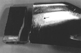
In the first case, the polycarbonate handle of an angle grinder fractured suddenly in 1998, and the revolving wheel struck the user in the groin, injuring him severely (Fig. 8.9). He had bought the machine about two years before the accident, and was well used to operating power tools, having been a metal fabricator for many years (according to his witness statement). He was using it to sand down some woodwork, so was supporting the main body with his right hand and holding the handle with his left when it fractured. He dropped the tool and managed to reach the house, leaving a trail of blood behind him. His life was saved by the arrival of the ambulance, but he spent some time in hospital where he received transfusions owing to the great loss of blood. He sued the suppliers of the tool. The grinder was not a well-known brand, and was of a type that has been imported in large numbers from the Far East, and sold at discount prices in supermarkets. It was one of the smallest such machines on the market.

8.4.1 Fracture surface
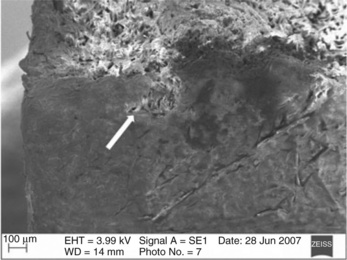
The fracture occurred where the guard joined the stem, above the screw attachment to the grinder (Fig. 8.10). The underside of the guard itself showed severe contamination leading from the gate in the form of discoloured polymer with sharp boundaries (Fig. 8.11). The material of construction was found to be polycarbonate, a polymer which needs careful control of process conditions to achieve its greatest strength, as was seen with mining products. The fracture surface on the machine side showed impact damage along one edge, probably caused when the user dropped the device and it hit the floor (Fig. 8.12). The rest of the fracture showed growth of a single crack which met at one point to form a cusp. However, the handle side of the fracture revealed numerous striations (width about 30 microns in diameter) next to the sharp outer corner, caused by fatigue (Fig. 8.13). It was estimated that the striations covered about a quarter of the section area before the section could no longer support the applied load, and it suddenly failed.


So what had initiated the fatigue striations? There appeared to be several points on the outer corner where the process had started (Fig. 8.13) and their position was not coincidental. They appeared to occur where there were tiny defects in the corner such as weld lines and voids, the latter being associated with the visible contamination of the guard (Fig. 8.11). The bending load imposed on such a handle will have been low, and will have been concentrated at the sharp outer corner where defects were present. An estimate from the measured radius of curvature of the corner of 0.05 mm gave a stress concentration factor, Kt, in excess of about 5 (3). Using the same calculation gave a Kt of about 3 and 1.45 for the handles shown in Fig. 8.10, newer handles supplied with other angle grinders of similar design. If there was a void present at the sharp corner, then Kt will have been at least 10. So a small load of say 1 kgf applied to the handle will have been effectively 10 kgf at the corner. The tensile strength of the polymer was unknown but would probably have been low owing to the contamination and/or degradation seen in the guard.
8.4.2 British Standard for tools
In response to the action, the tool suppliers said that they had not seen any other failures of this type, and that they tested a selection of the tools to a British Standard (4), a test involving a drop impact test of some severity. However, they did not specify what numbers they had actually tested. The standard does not specify any detailed test of handles.
It was very clear from the investigation that a faulty handle had indeed been supplied with the tool when purchased, and the injured user was compensated before trial. His occasional use of the tool had created small hairline cracks to develop at the very weak outer corner to the guard, cracks which grew at every use of the tool. The cracks will have been difficult if not impossible to spot given that they would be black against a black background. When they reached a critical size, the handle suddenly broke and the user was severely injured. One might have thought that such tools would be recalled for replacement of the faulty handles, but one of us (PRL) saw similar defective handles on new grinders in a local supermarket after the case settled. One hopes that the faults were found before further accidents occurred. The poor design was corrected later by increasing the radius of the outer corner, but the quality of some imported new tools leave a great deal to be desired.
8.4.3 Another handle failure
A not dissimilar accident occurred on 20 March 2003, when the plastic handle on an angle grinder suddenly broke as the user was cutting metal using an abrasive disc (Fig. 8.14). He had bought the machine about a year before and had hardly used the device before the accident occurred. The discs on grinders are rotated at a very high speed of several thousand rpm, so when the handle failed, the grinder dropped onto his hand and he was very seriously injured as the rotating wheel cut deeply into his flesh. He then sued the manufacturer, and we became involved in 2006 after the manufacturer claimed that their tests showed that the handle needed a force of 75 kg to break, a value well above the load any user could reasonably apply to the handle. The problem needed resolution.

8.4.4 The fracture
The broken handle showed a completely brittle failure (Fig. 8.15) near the point where it joined the body of the grinder by means of a screw thread. Exposing the matching fracture surfaces showed that the break had occurred across the top of the metal bolt embedded in the plastic, and it showed several serious defects (Fig. 8.16). Comparison of the two surfaces showed that the plastic had shrunk away from the top surface of the bolt, and a large weld line was present in the shrunken surface (at right in the figure). The same surface also showed traces of a number (48) transferred from the head of the bolt to the molten plastic during injection moulding. It showed that the plastic made contact and then shrank back as the polymer cooled, a common problem when the melt is too hot and the cooling too short. The depth of maximum shrinkage was 1.7 mm at the centre.


8.16 The upper fracture surface showing shrunken interior and large weld line plus faint traces of a number ‘48’ from the bolt head. Impact damage at lower left.
The origin of the fracture was clearly identifiable by the convergence of hackles in the surface (Fig. 8.17). So what was present at the origin? There was clear evidence of voids between the metal edge of the bolt and the surrounding plastic, formed in the same way as the shrunken centre of the upper part of the handle (Fig. 8.18). They would have acted as stress concentrators, by magnifying an innocuous local stress applied by the user to a level where it challenged the tensile strength of the material.


8.18 Close-up of fracture origin with void at interface with bolt, and flat part at base caused by handle guard hitting the floor.
The material of the handle was said to have been a glass-filled grade of nylon, or polyamide 6 (a report from the manufacturer said that the material was ‘PA6 + GF30’). However, FTIR spectroscopy indicated a mixture of nylon 6 and 66, an inference supported by DSC, which showed two separate melting peaks, one at 216 °C, and the other at 256 °C (Fig. 8.19). The polymer was a mixture of two different polyamides, nylon 6 and nylon 66. Nor could any trace of glass fibres be found in the samples taken for analysis, contrary to the information from the manufacturer that the material contained no less than 30% short glass fibres. If that were the case, fibre ends should be seen everywhere on the fractures. None in fact could be seen at all. It seemed that the specification may have been changed, or that a non-recommended material had been used.

8.4.5 Conclusions
The fracture surfaces showed that premature failure had occurred from pre-existing defects formed during manufacture of the handle. But the manufacturer insisted that their tests of new handles showed them to be quite strong enough to resist normal forces applied by users. It is interesting to note that their intact handles also broke in a brittle way at a similar position near the bolt head, confirming that this was the weakest area of the handle. This is a consequence of the very big difference in stiffness between steel and nylon, so that any loads on the handle are borne solely by the polymer. The most likely loads are bending, when the hand of the user pulls or pushes the handle to control the position of the grinding wheel.
When the handle is bent, the maximum loads are transferred to the polymer, and a small part to the interface between the steel bolt and the adjacent plastic. The failure load on new handles tested by the manufacturer showed that a load of 75 kgf was needed to cause fracture, although fracture could also be induced by impact loads. They therefore suggested that the user had dropped the grinder to cause the failure, although they could not explain why or how the user had been injured so seriously. They also said that of 30 000 such grinders sold, none had showed a similar failure.
Unfortunately, the failed test samples were not made available for comparison with the accident handle, and the tester had not recorded the state of the fracture surfaces or inner defects they exposed. However, the severity of the voids and prominent weld line suggested that the accident handle was a maverick sample made in the early stages of a moulding run when injection conditions had not been fully established. If the molten nylon had been too hot, for example, shrinkage would have been severe (as found) and numerous voids formed in the polymer. Such samples should not have passed quality control, but sometimes they can creep through, perhaps because they seem of good quality judging simply by externalappearance. A maverick handle was enough to explain the fracture at very low loads from the user, and there also remained the problem of the specification. The defendant’s theory that the grinder had been dropped did not stand scrutiny: the external surfaces of the handle showed very little wear or damage caused by impact. The only impact damage found was on the fracture surface itself (Figs 8.16 and 8.18), showing that it had dropped after the accident and not before. The case was settled with damages for the injured user.
8.5 Failure of security caps for gas cylinders
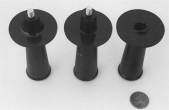
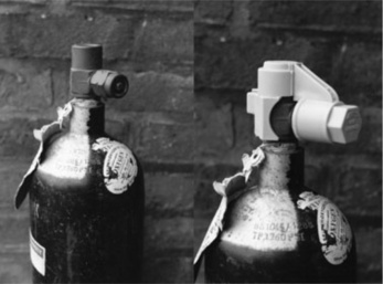
There have been many innovative ways in which polymers have been used to create new designs fulfilling unexpected functions, such as the development of security guards for gas cylinders used in hospitals. The product was designed to be fitted around the tops of gas cylinders to protect the valve as well as show the user what gas was present in the cylinder by colour coding the plastic (Fig. 8.20). Although not strictly a consumer product, the case study is included here because the way the problem was solved involved the same principles discussed in the cases of tool failure.
A problem was discovered in 1988 by the manufacturer, an injection moulder in Leicester, who found that caps were falling apart before ever being used on gas cylinders. The devices were made in talc-filled polypropylene in four colours and made with two flaps which are brought together in a secure joint around the top valve of the cylinder. The flaps are hinged at two points to allow rotation of the flaps (Fig. 8.21). The non-return parts of the joint can be seen at extreme left and right. The cap is removed at the hospital by applying a hexagonal spanner to the front of the fitted device. Although disposed of after removal from a cylinder, the unattached caps must be able to resist dropping and handling loads before fitment.

8.5.1 Storage failures
However, whole batches were found to be failing at the critical hinges when held in storage, and had to be returned to the moulders for scrapping. Indeed the warehouse at the factory was full of rejected products, a sight which horrified the owners and led to a panic phone call to help resolve the crisis.
There were several possible causes, poor material being the one favoured by the moulders, perhaps not unsurprsingly. Samples of material were thus cut from a selection of good and failed mouldings to test the theory using FTIR spectroscopy and DSC. However, no anomalies could be found at all using these methods, so poor material by degradation, for example, could be excluded. The spectroscopy showed a high ethylene content of about 10%, making the material both tough and very flexible. Attention turned to the way they were moulded, since this was now the likely source of the problem.
The device was moulded via no less than four gates: one at the centre of the hub of the cap (Fig. 8.21 shows the sprue remnant of this gate), two on each of the side flaps and one at the centre of the device diametrically opposite the first gate, as shown by the arrows in the photograph. There were a number of irregularities in the moulding parameters, especially the barrel temperatures of the moulding machine. The setting sheet showed the sequence:
while the thermostat set temperatures were:
These large differences could change the product in unexpected ways.
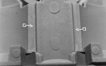
A large number of new devices were then examined for any defects, and were also tested by fitting on a cylinder head. A key observation came very quickly when considering the integrity of the device. The weakest parts were the hinges about which the flaps rotated to lock the device in place. They consisted of plastic only 0.5 mm thick and running the length of 20 mm along each side of the flaps at the base of the hub (HH in Fig. 8.21). The two lengths of polymer had to be strong enough to resist handling and bending to form the hinge, but yet weak enough to give way when the cylinder was needed. It was noticed that many samples that failed prematurely exhibited weld lines at or on the hinge, the weld lines having formed by impingement of the three streams of molten polymer entering opposite the hub of the device. Failed samples invariably possessed such weld lines in the hinge rather than in the bulk polymer (Fig. 8.22). And those weld lines varied erratically from sample to sample. Of sixteen samples tested, only five survived fitment to the oxygen cylinder (Fig. 8.20). The remainder showed splits or cracks in the hinges. A quantitative test was needed, as well as close attention to moulding conditions.
8.5.2 Development of torque test
What was needed was a simple objective test that could meet the needs of the end user and yet be easily applied in the factory. To develop the test, a mole wrench and spring balance were used under standard conditions to measure the torque strength of the fitted caps. The caps that showed hinge cracks gave very low failure torques, as might be expected, with values ranging from 0 to a maximum of 8.3 Nm, but the average result was only about 4 Nm. By contrast the five intact caps gave an average of 8 Nm with a maximum value of 19 Nm (but failed in the case rather than the hinge). The strength also varied depending on the colour. There was a linear relation between the length of weld line in the hinges and their torque strength, confirming that weld lines were indeed the cause of the problem of premature failure.
Such a spread of results was quite unacceptable for the customer, who needed a reliable guard cap that would fail only when a spanner was used on the device. Moreover, the failure torque needed to be relatively high to necessitate use of a spanner. The ergonomic literature gave some interesting results (Fig. 8.23) which showed that when the hand gripped cylinders of various surface textures and diameters, there was a maximum torque that the hand could exert. The maximum was lower for women, and the obvious choice was that for males, since it was greater (2,5). Using the data shown in the figure, and the diameter of the hub as 35 mm, then the maximum torque that can be exerted is about 0.8 kgf-m or 8 Nm for a knurled steel cylinder. So moulding conditions should be varied, first to move the weld lines away from the hinge, and second to give the hinges a torque strength of at least 8 Nm. This would mean that the hub could not be removed by hand action, requiring a spanner to twist the guard free.

Returning to the factory with the recommendation that moulding be stopped to reset the moulding machines, did indeed save the situation. The change in conditions moved the weld lines away from the hinges, and samples were again taken for testing. The strength of the new samples averaged 12 Nm and was much more consistent. Far from being a material problem, the moulders should have taken greater care in monitoring their moulding conditions and inspected their products to eliminate the damaging weld lines.
8.6 Failure of an ABS handle
Wherever the consumer frequently uses a product then handles are normally designed into the product. The low-level water closet is a case in point, and failures can be both dangerous and inconvenient. In one such case, the consumer cut her hand when using such a handle, and claimed damages from the manufacturer. She supported her claim by instructing two experts, both of whom concurred that the design was poor and the material (ABS plastic coated with chrome metal for a polished finish) suspect. They thought that it had failed by simple fatigue.
But the case was not as straightforward as the reports indicated. The investigation started with close inspection of the failed handle itself, showing that it had cracked across its major axis in a brittle way and so leaving sharp edges to the fracture (on which the user had been injured). Figure 8.24 compares an intact and the cracked handle, showing that it failed roughly halfway along its length, starting on the upper visible side. The fracture surface revealed numerous striations in the upper part, followed by a fast crack region (Fig. 8.25 with interpretation in the fracture map of Fig. 8.26). The handle must have failed progressively from a surface defect on the upper wing, the brittle crack growing slowly at every use until it reached a critical size and the handle suddenly broke into two parts. This must have been when the claimant was injured by the sharp edge of the cracked handle.


8.25 Fracture surface of handle with striations from origin in top wing and showing crack growth direction.

The key question now was why had the crack started and then grown slowly to completion. Further inspection of the failed device gave several clues as to the causes of failure. In the first case, there were several scratches near to the fracture surface, one of which was severe (Fig. 8.27), and from which the chrome had peeled back to reveal the white ABS plastic beneath. The second clue came when the underside was examined (Fig. 8.28). It showed numerous etch pits where the ABS polymer had been attacked by an aggressive chemical. The pits were globular in shape, indicating a chemical cleaner which had formed droplets at the bottom of the handle, from which attack of the underlying plastic had occurred. It was now possible to formulate an idea of how the crack had started. Constant and daily use of the handle had caused scratches to occur in the chrome protective layer, perhaps from a ring on the hand of the user. Regular cleaning with a powerful reagent such as bleach had then attacked the polymer below and caused a stress corrosion crack to develop and grow with every application of load by the hand of the user.

8.6.1 Scanning microscopy
The theory was confirmed by SEM and EDX analysis, large quantities of elemental chlorine being found on the fracture surface. Bleach is usually a strong aqueous solution of sodium hypochlorite, which liberates free chlorine when used, and indeed is the basis of the powerful cleaning action. However, it also attacks many plastic materials, and will promote brittle or SCC cracks on an unprotected polymer such as ABS. The case was withdrawn just before trial. It is interesting to observe that the initial investigations jumped to conclusions that were quite wrong, largely because the investigators failed to look further than the fracture surface itself. Damage elsewhere on the failed handle showed the collateral damage of the reagent which had actually caused the critical crack. There was one final point: the user will have seen the crack opening every time she used the handle, especially towards the end of its life, and it should have been a warning of a broken product in need of replacement. Unfortunately, she took no action until the handle broke and she was injured. But there could be no case against the manufacturer for making a faulty product.
8.7 Failure of chairs manufactured from polypropylene
Increasing confidence among designers has led to a veritable explosion in plastic products, among which furniture is notable, especially chairs. Their use has expanded greatly in recent times, both in public venues like cafes and restaurants as well as private homes. With their resistance to the weather, they have become a popular choice for garden furniture after initial problems with UV resistance. Manufacture of a complete product in one operation ensures costs are low, so they have been widely adopted for public venues involving large numbers of people. But there have been other problems with the choice of polymer and their intrinsic strength. When a plastic chair fractures suddenly under the weight of the user, he or she can be injured seriously. Problems can occur with choice of the material, the way it is moulded and the design of the product, especially at critical parts such as inner corners where the stress imposed by the user is concentrated.
Failures of chairs of any kind are not uncommon, owing to deterioration during continuing use. Wear at joints is an obvious failure mode, especially on old chairs where the screws have worked loose in the wooden frames. Glues will deteriorate and dowels can fail if rotten. But the cases described here involved new chairs, and specifically a plastic chair moulded in Italy. A woman in Lichfield in the Midlands was injured in 1996 when the back leg suddenly fractured, and she fell to the ground, in a case referred by the insurers. The chair had been bought new only a few days before the accident, so failure could not have been caused by ‘wear and tear’. The back legs had failed suddenly by brittle cracking (Fig. 8.29), one of the legs being completely detached from the rest of the chair. The other rear leg showed sub-critical brittle cracks from the rear upper corner. Closer inspection showed that there were two critical cracks which had intersected to form a cusp at the corner itself (Fig. 8.30). In the optical microscope, the material (chalk filled polypropylene) showed large internal voids from which the cracks had initiated (Fig. 8.31). The stress concentration at a void is about 2 for a spherical void, increasing as it becomes elongated. And since the corner itself also represented a serious stress raiser, there could be little doubt that the local stress had exceeded the tensile strength of the polymer.


8.7.1 Material analysis
Spectroscopic and calorimetric analysis confirmed the material as polypropylene, with a small carbonyl peak in the FTIR spectrum, showing that some degradation had occurred during processing. The existence of voids within thick moulded sections is caused either by degradation producing gas, or by an intrinsically weak polymer unable to resist depressurization at the end of the injection cycle. It is likely that a combination of both processes occurred in this instance, so the material was too weak to resist normal loads. The insurers suggested that the user was ‘a heavy lady’, a proposition which turned out to be false. Although she was pregnant at the time, her weight was only 11 st 13 lbs (or 74.4 kg) rather than 16 stones (or 102 kg) suggested by the insurers. In any case, the British Standard for chairs provides for a minimum supported weight of 1100 N or 112 kg for chairs of ‘careful domestic’ type. The same Standard (6) also suggests that such chairs be tested to such static loads, as well as resistance to fatigue and impact loads. It is possible that the failed chair was a maverick, although a later case involving the same design indicated a deeper problem.
8.7.2 Another failure
Following compensation to the injured woman from Lichfield, a not dissimilar failure occurred in August 1998 at a holiday camp. The female user was supervising her children in the swimming pool, and was sitting in the white plastic chair when the front leg suddenly fractured, and she was injured when she hit the concrete floor edging the pool. She sued the company running the camp and the manufacturer of the chair. It was very similar to that which had failed in 1996 (Fig. 8.32), differing only in the design of the drainage holes in the base. Inspection of the fragments showed that the fracture had started near the front corner (Fig. 8.33), while microscopy showed the origin had occurred from a void near the corner (Fig. 8.34). As in the previous case, there was no evidence of fatigue, surface damage or UV degradation.


A new chair of identical design was provided and failed in a similar way when the front leg was pulled by hand. It was estimated that the leg cracked with a pull of only about 12 kgf. Although the weight of the injured woman was unknown, such a low strength suggested that the chair was fundamentally flawed. This type of load would be generated by the woman leaning forward so putting all her weight at the front of the chair, with a heavy downward load tending to splay the front legs outwards.
8.7.3 Litigation
Because the injured woman had initiated a court action, the defendants asked for an independent report from another expert. He examined the same samples and re-measured the force needed to shear the front leg away at about 20 kgf. He analyzed the material and found a chalk content of 27–28%, a rather high level for a polymer. But he came to different conclusions because the design had been tested by official testing agencies in Italy and Germany, but of course, such testing will be misleading if moulding conditions varied from batch to batch (as seen in the security guard samples). Although he confirmed the presence of voids, he thought that they had not contributed to the failure. But lightning rarely strikes twice in the same spot, and the failure of a second chair in the same material to a very similar design suggested that the design was faulty. Despite requests to obtain moulding data (such as setting sheets and QC tests details), they were never produced, and the case settled with compensation for the injured woman.
It is surprising what little attention manufacturers give to the detail design of products, details which can weaken a product so much that it endangers users. Polymers are especially liable to degradation and it is often seen by the occurrence of voids in what should be solid material. They remain hidden within the bulk and so are truly patent rather than latent defects, waiting for a critical stress that will cause sudden fracture. Other sudden fractures were encountered during the same period in the author’s own garden, although happily without injury, and it is to be wondered how many failures go unreported. As with many other common low-cost products, failures are rarely reported if no injury has occurred, which is perhaps why many manufacturers claim no knowledge of premature failures of their products, despite circumstantial or hearsay evidence to the contrary.
8.8 Failure of swimming pool steps
But other safety-critical products can fail, too, such as steps beside swimming pools to allow access to the water (Fig. 8.35). A 12-year-old girl suffered leg cuts when a plastic step suddenly broke while she was ascending the ladder in June 1995. The step had only been installed for four weeks as new, so the failure was unusual, especially since the rest of the steps were made from the same material (ABS) and had been there several years. The step appeared to have broken from two points near the supporting tubes to which it was fixed, so as to give a large free fragment and two parts still attached (Fig. 8.36). Close inspection of the fracture surfaces showed that the larger attached part had broken first, the critical crack growing from near the support in the upper part of the step (Fig. 8.37). The step then cracked again to produce the final form. The exposed surfaces were covered with fine ‘crazy-paving’ cracks indicative of oxidative cracking, and there were also numerous weld lines in the moulding.

8.35 Swimming pool ladder with top step replaced after failure; lower steps of same design as failed step.


8.8.1 Fatigue crack
SEM showed the origin of the critical fracture with numerous striations below (Fig. 8.38). There appeared to be a series of pits or cracks on the upper surface from one of which the crack grew progressively every time the step was used. The user’s father weighed substantially more (16 stone, 100 kg) compared with the girl’s weight of only about 7 stone (45 kg), but when the cracks reached a critical state, only the smallest weight would have been needed for sudden fracture.

The step showed signs of extensive weld lines, and was probably moulded cold rather than when the machine had reached equilibrium temperatures. ABS is normally a tough and ductile polymer, and should not behave in a brittle way under moderate loading. Calorimetry showed a slightly lower glass transition temperature (Tg) than an intact step, and extra peaks detected in the FTIR spectrum pointed to degradation during moulding. There was a noticeable yellowing of the failed step when compared with an intact step. The crack had started at a weld line, a line of inherent weakness where the polymer has not fused correctly. Even though the load near the top of the step was lower than below, the stress was enough to cause an inherent defect to grow slowly to failure.
8.9 Failed polyamide fittings in ladders
Using polymers in safety-critical parts has become widespread in a range of consumer products, not just in special ladders such as that considered above, but in most extension ladders and stepladders of all kinds. Although most are made from aluminium alloy, key polymeric parts are often supplied for the feet and tips, as well as joints. But care is always needed in interpreting failed or broken components. In a previous case study, an extension ladder dropped suddenly and the user suffered severe injury (7). He blamed the plastic tips because they were found fractured after the event, but the incident was more complex. Analysis of the mechanics showed that the ladder fell because it had been leant at too shallow an angle against the wall of his house. The tips fractured as a result of the slip, and were not the cause of the accident, so his case could not proceed.
On the other hand, a painter fell from a ladder when it had been leant at the correct angle (about 75 degrees to the horizontal). Inspection of the skid marks left by the feet showed that one of the rubber feet was defective, and made the ladder unstable (Fig. 8.39). When the user put his weight on the ladder, it was pushed back into the hollow stile, so the aluminium stile end was resting directly on the tiled surface. The coefficient of friction was much lower, and when the user was near the top of the ladder, the bottom suddenly slipped away, and he fell about 20 feet (6 metres) to the ground and was severely injured. His employer was responsible for maintaining the ladder in good condition, and so he received compensation. Stepladders are also widely used both in the workplace and in the home, and although of limited height compared with extension ladders, users who fall can either suffer injury themselves or injure others standing nearby.
8.9.1 Failed stepladders
In another case, the joints suddenly failed and although the user himself was not hurt, his wife standing nearby was hit in the face and suffered injury. The investigation was made in 2007 following the earlier accident, not on behalf of the injured party, but on behalf of the ladder manufacturer, who wanted to determine the cause or causes. The device was a three-way combination ladder with two short aluminium ladders held together by two moulded nylon connectors (Fig. 8.40). The blue connectors were designed to allow movement of the ladders into different combinations, both as a conventional stepladder and as a short extension ladder. The two parts could then be locked together by means of two fittings in slotted composite plates (Figs 8.41 and 8.42). The upper fitting and the plate are separate mouldings held together by a rivet. Failure had occurred in the upper fixing, with two projecting knobs (or stubs) which abut above the aluminium steps, and so hold the ladders in position. One theory put forward by the manufacturers was that the user had incorrectly placed either one, or both stubs below the steps, so the ladders were insecure. When they slipped, the stubs impacted the rung below and they snapped.


8.42 Moulded composite connector riveted together (3) and sharp corner (arrow).
The failed ladder showed that both stubs had broken in the accident, so allowing the ladders to slip apart (Fig. 8.43). It was reasonable to suppose that the weakest one had broken first, and then the other failed by overload. But which stub had failed first and what design factors weakened either or both of them? Inspection of the fracture surfaces showed some defects, such as a void within one of them, and a band of dark blue within the other. The former might indicate degradation, the other poor mixing of the pigment with the matrix polymer, but neither were causes of premature failure since the fractures had actually started at the very sharp external corner where each stub met the parent fixing (Fig. 8.42 shows the sharp corner in section). Examination of intact stubs showed the abrasion damage where the stubs had rested against the metal steps of the ladder (Fig. 8.44). Considerable pressure must have been produced against the stubs as users ascended the ladders, and put them into bending, with stress concentrated at the sharp corners. An estimate of the stress raising effect of the corner was made using Peterson (8), and gave a value of Kt ~ 5 with a corner radius of 0.05 mm. The material was said to be a glass fibre filled nylon with about 30% filler content. The material is used widely where strength and some resistance to temperature is needed such as under-the-bonnet applications. A previous case study concerned a failed radiator tank, for example, where poor moulding produced weld lines which caused a leak, and eventual seizure of the engine (9,10) (Figs 2.8 and 2.9).

The corresponding corners of the metal steps also showed considerable distortion due to the localapplied loads transferred by the weight of the user standing on the ladder. Such an obvious interaction should have been considered during the design phase of the product and eliminated by reinforcement of those steps.
8.9.2 Scanning microscopy
The solution to the problem of tracing the weakness came by examining the fractures in ESEM. The remains of a serious weld line penetrating the corner was found at one point near the left-hand outer corner (at right in Fig. 8.43, ESEM image in Fig. 8.45). It can be recognized by the smooth areas leading from the surface from the corner into the fracture surface. The weld line represents polymer that has not fused, so a line of weakness occurs, and is in effect a proto-crack in the material. When such a feature occurs at a sharp corner, the stress raising effect is very high indeed, considerably greater than the estimate of 5 from the geometry of the corner itself.

The weld line represents poor moulding practice, since polymer should be hot enough during injection into the tool to fuse correctly. However, the gate of the part lies at the base of the part so polymer melt has a long path to the stub, and can cool down substantially before meeting other melt fronts. Such defects tend to occur at the start of a batch run, and must always be rejected, even though the part seems correct dimensionally and visually. The occurrence of poorly mixed polymer visible in one of the fracture surfaces tended to confirm the diagnosis (Fig. 8.43).
The theory that the user erected the steps incorrectly was not supported by the evidence, because the top step showed distortion downwards at the two corners to the stiles, and the damage could not have been produced by impact. Only lower steps could have been damaged like this, so the distortion to the top step must have been made by steady pressure during use.
8.9.3 Another accident
As the failure was being researched, another failure of the same design was reported, and although the plastic parts were of black polymer, the failure mode was very similar. The failure of another new ladder had been experienced by a man trimming his 1.8 m high hedge, and he was injured when the stepladder collapsed. The stiles slid back and he fell through the rungs with the trimmer still working. Fortunately, he was not injured seriously, but his legs were bruised by the fall. Judging by the traces of white paint on the stubs and elsewhere, he had been using the ladder for other jobs before the failure (Fig. 8.46). The white paint traces also show contact abrasion when the ladder was used after painting. Both stubs had failed where they joined the major part of the fixing, breaking from the sharp corner as before. Comparison of the failed with a tested ladder showed that the materialappeared rather less intensely black in the failed material, so scanning microscopy was used to examine the fracture directly.

8.9.4 Scanning microscopy
The inspection proved interesting in showing that areas of the composite appeared depleted in polymer with gaps and voids between the exposed glass fibres (Fig. 8.47). Such a condition could be caused by degradation, a problem possible in nylons by inadequately dried polymer prior to moulding. The hot nylon in the barrel of the moulding machine degrades by hydrolysis. Such voids present at a sharp corner increase the stress there since stress raisers are multiplicative rather than additive. So if a spherical void (Kt = 2) is present at a corner, the net effect is to double the stress concentration at the corner (11), from Kt ~ 5 to ~ 10.
Once again, the evidence pointed to faulty mouldings rather than user abuse, since the same distortion of the top step corners had occurred. If the stubs had been placed below rather than above the top step, the slip occurs very quickly and should be obvious to the user. Placing just one stub above and the other below was not only difficult but also easy to spot and rectify.
8.9.5 Product design, quality and testing
The two failures thus had a common cause: faulty mouldings that were insufficient to bear expected loads. They raised serious questions about the way the product had been introduced into the consumer market, especially in terms of the original design, the extent of testing of prototypes, the monitoring of moulding conditions, and the quality control of the new composite connections. And there had been other failures, like the brittle fracture along one edge holding the connector to the ladder stile (Fig. 8.48). In this case, brittle fracture had occurred along an edge of the large plate moulding which was attached to the stile of the ladder. The entire length of plastic had fractured, so releasing the fixing entirely. Another rib has also fractured (at lower left in the picture), and a large and deep weld line could be seen running from the top into the side of the moulding. It is likely that another weld line also caused the long fracture at right.

The product was withdrawn from the market following these failures. Even though the majority of the products may have been strong enough for regular use, the risk of only a small number failing suddenly was too difficult for the company to face. Much more serious injuries could have occurred and a subsequent court case would have been expensive to fight. The negative publicity would also have damaged the reputation of the company. Traditional designs of stepladder continue to be made and sold, but they normally rely on a folding table at the top of the two ladders which gives a very firm anchor to the device. Alternatively, a set of sliding supports links the two ladders together near the base.
Accidents still occur since ladders are so widely used in both domestic and work environments, and can give rise to serious injury. Users can be quick to blame the ladder, but often they have over-reached sideways during painting, for example, and the stepladders have toppled. Sometimes, the user lands heavily on one leg, which becomes distorted. They then say that the leg has buckled due to faulty metal or joints, but the damage in many such cases has occurred after the event rather than during the accident and so cannot be blamed for the accident (12).
8.10 Conclusions
The growth of the Far East as a manufacturing centre has been remarkable over the last decade, with the price of tools falling dramatically from imports into Europe and the USA. It has been a positive benefit to business and domestic users, but should not mask the often poor quality of some tools. In the worst cases they led to severe personal injury, and in less serious cases to loss of function or loss of product. In the cases of the plastic handled knives, the design was so poor as to beggar the question how such products could have been made in the first place. Then there are products like the handles to angle grinders which are badly moulded, but when made correctly, perform well in service. That the designer realized the error in the sharp outer corner of one of the devices became obvious when other handles of the same model were compared. The consequences of failure when in use are horrendous because a grinding wheel can cut deep into soft tissue of the body, and is almost impossible to stop before damage has been done.
The safety guard for oxygen cylinders was an important advance for easy recognition by hospital staff of the correct grade of gas to be delivered to patients, but failed through poor monitoring of moulding conditions, allowing weld lines to enter the critical hinge on which the design was based. The moulders quickly jumped to the wrong conclusion by blaming the material, when they should have been keeping a closer eye on their own machines. They were faced with a total loss of credibility, but the solution lay in their hands. They should also have been testing their products, but a simple test was devised so they could monitor production very easily.
A handle fitted to a low level WC failed and cut the user, but the failure was more complex than initially met the eye. Inspection showed that the chromium layer protecting the surface had been deeply scratched, possibly by a ring on the hand of the user, and allowed stress corrosion cracking of the underlying plastic, ABS resin. A brittle crack grew over a period of time, by attack from a chlorine-based chemical such as bleach, and would have been visible to the user every time she used the device. She should have replaced the handle before it finally failed. The case against the maker of the handle could not be sustained. Consumers should be aware that cracked products are more likely to fail suddenly than those without visible cracks, and they should be discarded and replaced before any final fracture.
Chairs are commonly available in thermoplastics, especially for external use, and can also fail suddenly, but often without any prior warning of imminent failure. Even a fall from 30 inches (0.76 m) or so can cause serious injury to the back, and a particular design of polypropylene chair made in Italy failed suddenly shortly after purchase. The material of construction was poorly processed to shape, and numerous voids were evident inside the material at and near to the fracture. The strength of the chair was lowered further by geometric stress raisers, and would have failed the standard tests available (if it had been tested). Then another chair of similar design and material failed, again injuring the user, but this time became a court action. The chair design had been tested and approved by independent test houses, but investigation showed similar defects as before led to premature brittle fracture. The case was settled before trial.
Like many hand tools, ladders of all kinds are potentially lethal instruments if they fail when the consumer is using the device. Falls from ladders are one of the most common causes of death and serious injury in the home, especially among older people. Extension ladders cause the most injuries owing to their intrinsic instability, especially if the user is near or at the top. They should be tied at the top, or footed and certainly leant at 75 degrees to provide some security against slippage or toppling. Stepladders seem more stable but can still fail by toppling, although few expect the device itself to fail. But that is just what happened in several recent accidents when key connectors holding the ladder parts together suddenly fractured, all on one specific design which had recently been introduced onto the market. The parts had been injection moulded in GF nylon, and early unexpected failure was caused by moulding defects, either weld lines or porosity, within the polymer at a very sharp corner in the design. It should be a routine exercise to eliminate all sharp corners in polymer mouldings by polishing the tools before, rather than after processing to shape. But quality control also failed the company and allowed defective products to enter the market and endanger users. The hard lessons learnt in other products should be circulated more widely, which is one of the objects of the present book.
8.11References
(1) Pheasant, S., O’Neill, D. Performance in gripping and turning: a study in hand/handle effectiveness. Applied Ergonomics. 1975; 6(4):205.
(2) Drury, C.G. Handles for manual materials handling. Applied Ergonomics. 1980; 11(1):35.
(3) Pilkey, W., Peterson’s Stress concentration factors. Wiley-Interscience. 2nd edn, 1997. [Chart 3.10].
(4) BS EN 50144–1:1996, Safety of hand-held electric motor operated tools; Part 1 General Requirements.
(5) Pheasant, S. Body space-anthropometry, ergonomics and design. Taylor and Francis, Chapter. 1986; 16:231.
(6) BS4875 Part I: 1985, The strength and stability of furniture.
(7) Lewis, Rhys, Peter, Reynolds, Ken, Gagg, Colin, Forensic Material Engineering: Case Studies. CRC Press. 2004:273. [Chapter 8,].
(8) Peterson, R.E., Stress Concentration Factors. Wiley-Interscience. 1974:98. [Figure 73].
(9) Lewis, Reynolds and Gagg, op cit, Chapter 7 p 218 ff.
(10) Lewis, P.R. Premature Fracture of a composite nylon radiator. Engineering Failure Analysis. 1999; 6:181–195.
(11) Walker, P., Lewis, Reynolds, et al, Chambers Materials Science and Technology Dictionary. 1993:303.