
Project 2: 3D-Modeling an RC Helicopter Model
SOLIDWORKS is a 3D design tool. Just like all tools, the more you use it, the better you become at it. In this project chapter, you will be provided with project work that you can do to hone your skills. In this project, you will be 3D-modeling and assembling a helicopter toy model from a set of engineering drawings.
This project chapter will cover the following topics:
- Understanding the project
- 3D-modeling the individual parts
- Creating the assembly
By the end of this chapter, you will have more confidence in using the different SOLIDWORKS tools for practical projects.
Technical requirements
You will need to have access to SOLIDWORKS to complete the project.
Understanding the project
Understanding what the project entails is essential before starting the work. This will allow you to draw a plan and manage your work expectations towards completing the project. For this exercise project, you will be 3D-modeling a Remote Control (RC) helicopter toy, as shown in the following figure:
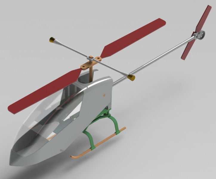
Figure P2.1 – The RC helicopter you will 3D-model in this project
The model consists of 16 parts, 12 of which are unique. The following figure highlights the bill of materials, showing the names of the parts, their quantity, and position in the assembly:

Figure P2.2 – The RC helicopter and its bill of materials
At this point, you already have an idea of the project's outcome and the complexity of the needed parts and assembly. In the following section, we will provide you with the engineering drawings needed to replicate all the parts and assembly. Now that we have an idea about the project's final output, we can discuss how you can tackle it in the context of this writing.
Important Note
The drawings and 3D models presented in this project are for practice purposes rather than for manufacturing purposes.
There are two ways in which you can tackle this project, depending on your 3D-modeling level. They are as follows:
- Moderate level: Take a look at the drawings and the provided sample procedure to complete the project.
- Advanced level: Only take a look at the drawings without using the sample procedure.
Other than the two suggested approaches, you can also follow your own way to 3D-model the RC helicopter without utilizing the provided drawings and sample procedures. Keep in mind that the sample 3D-modeling procedures provided are meant as a sample guide. They are not meant to present an optimal procedure, rather, you can look at them as one possible procedure to generate the models and assemblies. To grow your own 3D-modeling style, you can experiment with modeling the project using different modeling procedures.
Tip
You can treat the project as your own and customize the provided RC helicopter to end up with your unique design.
In this project, we will first explore the individual parts, then move into the assembly. So, let's get started with the parts. We will also provide you with hints that can assist you with your work.
3D-modeling the individual parts
In this section, we will explore the different part drawings that represent the RC helicopter. The provided drawings have enough information for you to replicate all the parts to end up with an identical result to the one shown in Figure P2.1. Thus, one option for handling the project is to create an exact replica of the given drawings. However, you can also choose to customize and adjust different elements of the design to make it your own. Keep in mind that this is your project, so feel free to treat it as such.
Exploring the individual parts
The provided RC helicopter consists of 16 parts. However, 12 of those are unique, which you will need to 3D-model, as highlighted in Figure P2.2. The parts you will need to 3D-model are as follows:
- Landing leg
- Landing arm
- Chassis
- Support
- Shaft
- Tail support
- Tail
- Blade Support
- Body
- Blade
- Tail blade
- Blade stabilizer
Important Note
The names of the parts presented in the bill of materials might be different than practiced names in the industry.
Your task is to use the presented drawings to 3D-model the individual parts. As you are 3D-modeling the different parts, keep in mind that there is no one correct way of 3D-modeling any of the parts. However, we will provide you with some hints for one approach that can push you forward if you find yourself getting stuck. You can also feel free to customize your design using the given drawings as a base of inspiration. The order in which the following drawings are presented is arbitrary.
Important Note
All engineering drawings are presented using the third angle projection.
Let's start exploring the drawings one after the other. The first drawing is for the landing leg:
Figure P2.3 – Detailed drawing for landing leg
Here is a sample procedure for 3D-modeling the landing leg:
- You can start with a swept boss to create the main shape, as shown in the following figure:
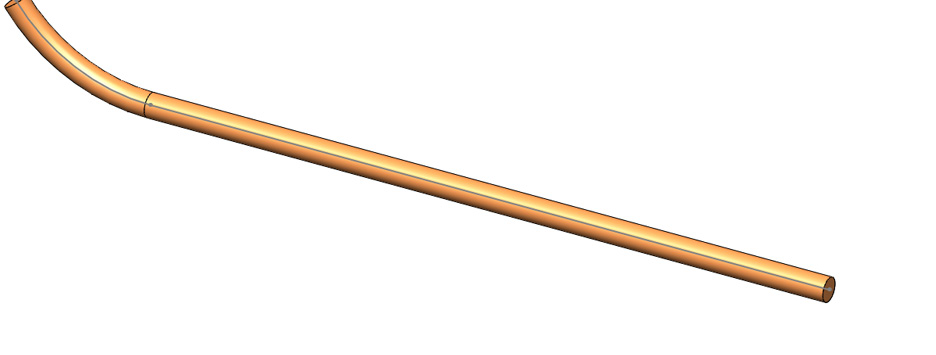
Figure P2.4 – Swept boss be used to start the landing leg
- Apply fillets to get the rounded edge.
Next, we can look at the landing arm:
Figure P2.5 – Detailed drawing for the landing arm
Here is a sample procedure for 3D-modeling the landing arm:
- Create a sketch highlighting the entire shape of the arm. Then, use an extruded boss with selected contours to extrude the long-connected shape:

Figure P2.6 – A possible first step in creating the landing arm is using an extruded boss
- Reuse the sketch from step 1 to extrude-boss the rings to get the final shape shown as follows:

Figure P2.7 – One sketch can be used for more than one feature
After the landing arm, we can explore the chassis:

Figure P2.8 – Detailed drawing for the chassis
Here is a sample procedure for 3D-modeling the chassis:
- Use an extruded boss to create the mainframe of the chassis, as shown in the following figure:

Figure P2.9 – An extruded boss can be used to create the mainframe of the chassis
- Use the fillet feature to round corners. Then, use an extruded boss and extruded cut to create the extensions and holes on the corners. You will get the following final shape:

P2.10 – The chassis can be finalized with fillets, an extruded boss, and an extruded cut
Tip
In general, it is a good practice to add fillets and chamfers at the end of the modeling process.
After the Chassis, we can take a look at the Blades. There are two blades in the RC helicopter, top blades, and tail blades. We can utilize configurations or design tables to create both blades in one part file. This is because both blades have similar design features. We will first create the top blade and then generate the tail blade out of it. The drawing shows the default (top) blade:

Figure P2.11 – Detailed drawing for the blade
Note the drawing has many variables without numerical values. The numerical values for both the default and tail configurations are presented in the following drawing:

Figure P2.12 – The two configurations for the blade
Here is a sample procedure for 3D-modeling the two blades:
- Use an extruded boss with the sketch shown in the following figure to create the main blade:
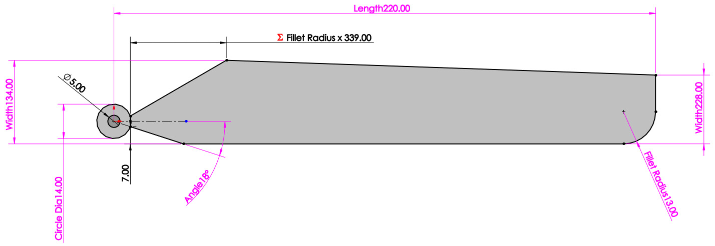
Figure P2.13 – step 2 An extruded boss can create the bulk of the blade
- Introduce a design table, as shown in Figure P2.14, to create the tail blade. Use the variables named in Figure P2.13:
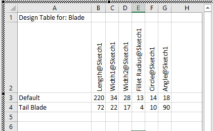
Figure P2.14 – step 3 A design table can be used to create the tail blade
- After introducing the design table, double-check on the generated configurations for the default top blade and the tail blade.
Next, we can look into the Shaft, which will connect most of the helicopter parts:
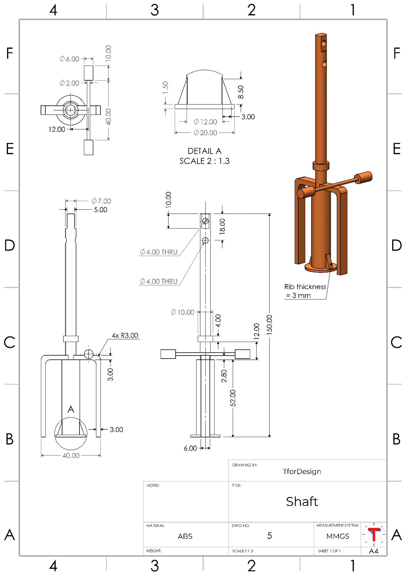
Figure P2.15 – Detailed drawing for the shaft
Here is a sample procedure for 3D-modeling the shaft:
- Use revolved boss to create the long part of the shaft, as shown in the following figure:
Figure P2.16 – Revolved boss can generate the long rod of the shaft
- Use the extruded boss and fillet commands to create the two legs on the sides of the shaft. You can create one side and then mirror the other side:
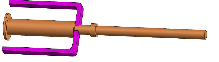
Figure P2.17 – Extruded boss, fillet, and mirror features can create the two leg-shaped figures
- You can create the sideway-looking antenna using a revolved boss. You might need to generate a new plane for that, as shown in the following figure below. You can get the exact shape using multiple applications of the extruded boss feature as well:

Figure P2.18 – A new plane was used as a base for a revolved boss
- Using extruded cuts, you can create a straight surface on top of the shaft and the two holes, as shown in the following figure:
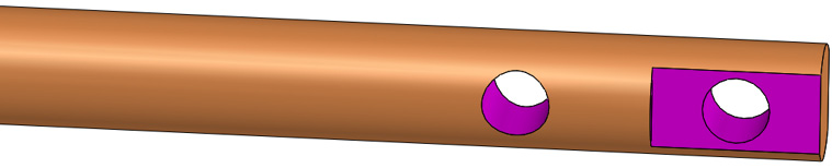
Figure P2.19 – The holes and straight surface can be made with an extruded cut
- Using the rib feature, you can create the two ribs on the lower part of the shaft. You can apply the feature twice or apply it once and mirror the result to the other side:

Figure P2.20 – The rib feature can be used to create the ribs
After the shaft, we can start working on the blade support, which will connect the blades with the shaft. The details of the blade support are highlighted in the following figure:
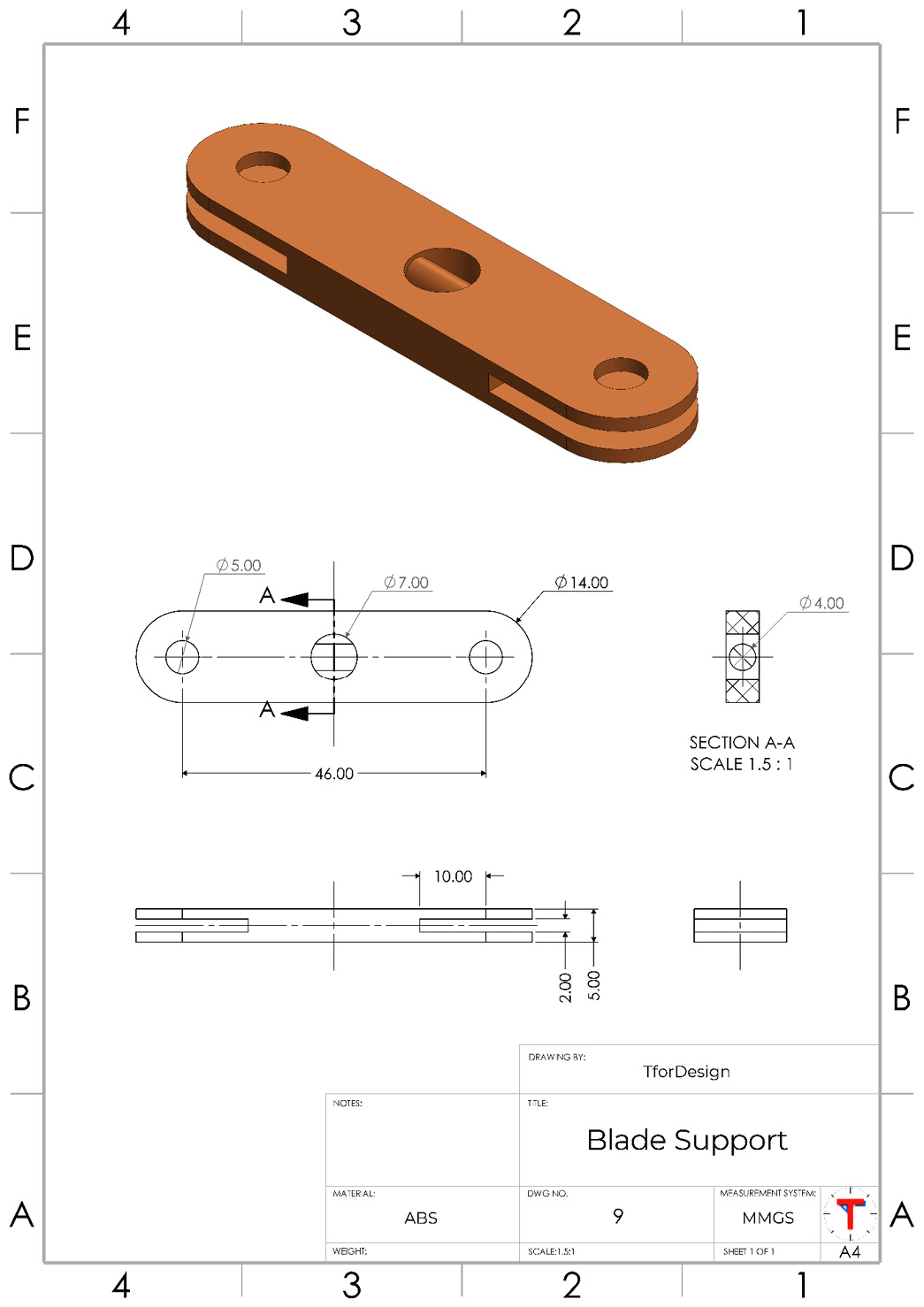
Figure P2.21 – Detailed drawing for the blade support
Here is a sample procedure for 3D-modeling the blade support:
- Use the extruded boss feature to create the following shape. When doing so, the Mid Plane end condition might make it easier to do the cuts in step 2:
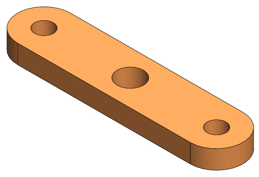
Figure P2.22 – One extruded boss application can generate most of the shape
- Use an extruded cut to make the slot in the middle of the shape:
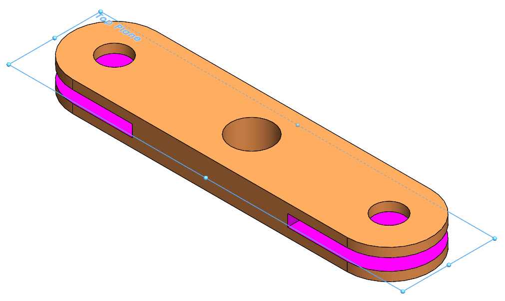
Figure P2.23 – The middle cut can be made with an extruded cut
- Apply another extruded boss to create the cylindrical rod located in the middle hole. You can use the Up To Next end condition to have the circular extrusion bounded by the surface:

Figure P2:24 – The 90 mm-long cylindrical part can be created with an extruded boss
Next, we can start looking at tail support, which will connect the tail to the support:

Figure P2.25 – Detailed drawing for the tail support
Here is a sample procedure for 3D-modeling the tail support:
- We can start by creating the bulky hollow part shown in the following figure. This can be made with the extruded boss, shell, and extruded cut features, in that order. Note that the bottom surface is removed using the shell feature. Also, note that the circular cut goes through both sides of the tail support:

Figure P2.26 – The hollow part of the tail support can be made with the shell feature
- The leg part of the support can be made with a lofted boss, as shown in the figure. Note that even though both ends are rectangular, they have different sizes, with the lower end not aligned with the side of the boxy area:

Figure P2.27 – Lofted boss can be used to create the long leg
- Use an extruded boss to create the lower straight foot indicated in the figure. Note that the foot is drafted. You can toggle the draft within the extruded boss feature or apply the draft as a separate feature:
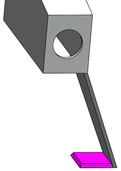
Figure P2.28 – A drafted extruded boss can be used to create the foot
- Use the feature mirror to mirror the lofted and extruded boss to the other side to get the shape shown in the following figure:
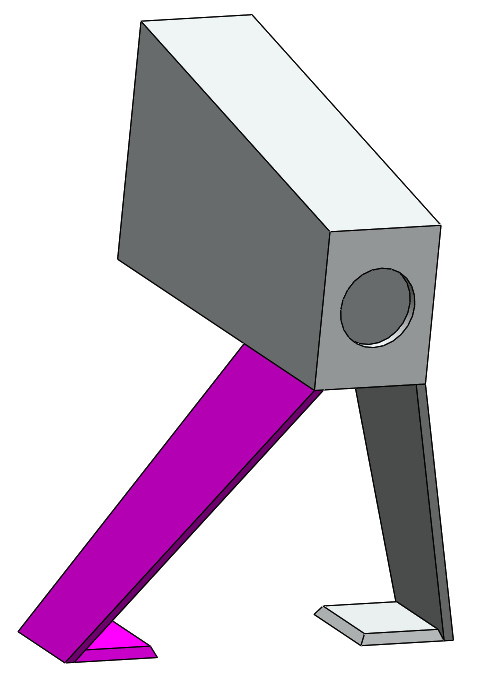
Figure P2.29 – The feature mirror command can quickly replicate features
Next, we can have a closer look at the tail, which will connect to the tail support at one end and the tail blades at the other end:

Figure P2.30 – Detailed drawing for the tail
Here is a sample procedure for 3D-modeling the tail:
- Use two extruded bosses to create the base of the tail, getting the shown result. To make sketching simpler, you can create one sketch and use it for the extruded bosses:
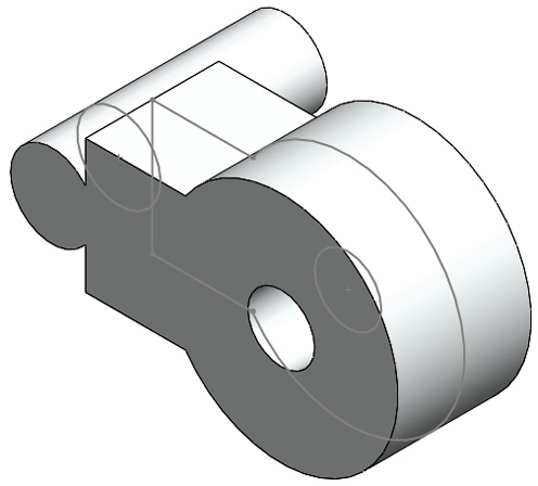
Figure P2.31 – The same sketch can be used twice for different features
- Use two other extruded boss features to create the disk-shaped part and its boundary. We can also use one sketch two times for two extruded boss applications:
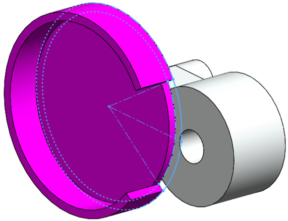
Figure P2.32 – Two extruded bosses with the same sketch can be used to create the disk
- Use the extruded cut feature to create the five cuts shown in the following figure. Note the cuts follow a circular pattern of six instances, with the one on the far right being skipped:
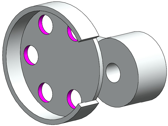
Figure P2.33 – The cuts on the disk follow a circular pattern
- Use an extruded boss to create the long part of the tail. As shown in the following figure, you might need to create a new plane as a base for the extruded boss:

Figure P2.34 – An extruded boss with a new reference plane used to create the long rod
Next, we will take a look at the support, highlighted in the following figure. Note that this can be a multi-body part:
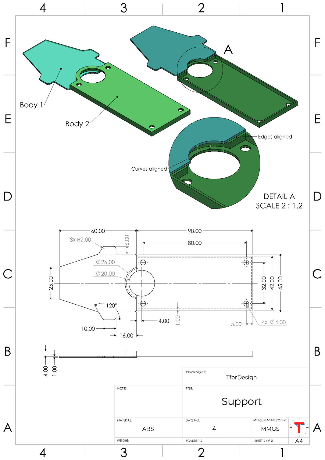
Figure P2.35 – Detailed drawing of the support
Here is a sample procedure for 3D-modeling the support:
- Use an extruded boss to create the flat part of the support, as shown in the following figure. We can include the fillets in the sketch or apply them separately as a feature.
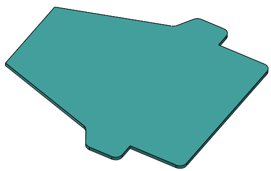
Figure P2.36 – Extruded boss can be used to create the shown body
- Use another extruded boss to create the second body, as shown in the figure. Make sure that the bodies are not merged by unchecking the merge result option. Note the first body was made transparent for clarity only:

Figure P2.37 – Extruded boss can be used to create another body
- Use the shell feature to shell the second body, as shown in the following figure:

Figure P2.38 – Shell can be used to shell only one body
- Use the extruded cut feature to create the final cuts. Note the larger cut applies to both bodies. Thus, we have to make sure both bodies are included in the scope of the cut. This should conclude the part, giving us the result shown in the following figure:
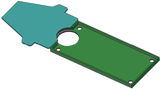
Figure P2.39 – An extruded cut applied to more than one body at once
Now, we can work on the blade stabilizer, as shown in the following figure:
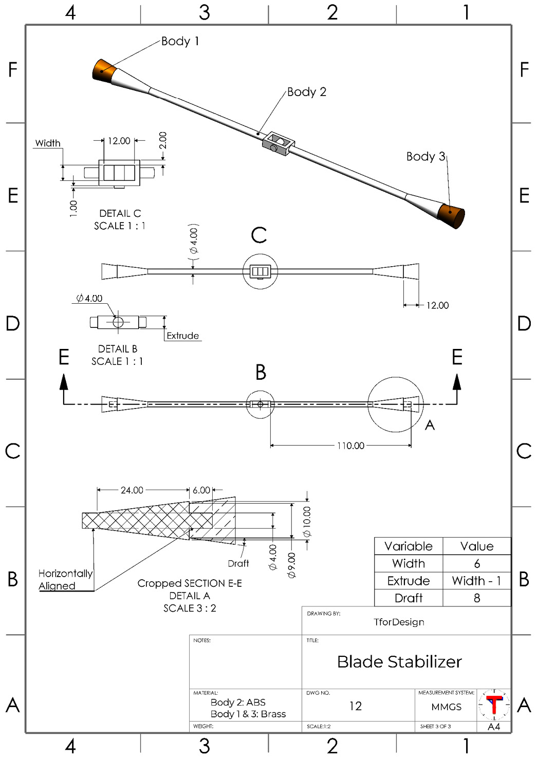
Figure P2.40 – Detailed drawing for the blade stabilizer
The Blade Stabilizer consists of three different bodies, two of which are identical. Also, some of the dimension of the indicated Extrude is related to the dimension indicated with Width. Here is a sample procedure for 3D-modeling the Blade Stabilizer:
- Use two extruded boss features to create the middle part of the blade stabilizer, as shown in the following figure:

Figure P2.41 – The extruded boss can be used to create the middle part of the blade stabilizer
- Use revolved boss to create the rod-like part, as shown in the following figure:

Figure P2.42 – Revolved boss can create the long rod with one application
- Create the brass part toward the tip of the stabilizer. Note that the part is drafted by 8 degrees, as shown in the drawing in Figure P2.40. We can set the draft angle from the PropertyManager of the extrude boss feature. Since the tip is a different body, we can uncheck the Merge result option when applying the extruded boss:

Figure P.43 – A drafted extruded boss can be used to create the tip body
- Create the hole on the tip part, as indicated in the figure below:

Figure P2.44 – The hole applied to a specific body
The location of the hole is covered by the main rod. To access the hidden location, you right-click on the body listed in the design tree and then select Isolate, as highlighted in the following figure. Alternatively, we can change the transparency of the other body:

Figure P2.45 – We can isolate bodies to make them easier to work with
- Mirror the revolved boss feature and the tip body to the other side to get the final result, as shown in the following figure. To do this, we will have to apply the mirror feature twice – once to mirror the revolved boss feature and once to mirror the body at the tip. This should conclude the part, giving the result shown in the following figure:
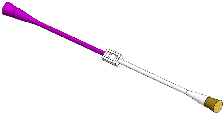
Figure P2.46 – Mirroring features and bodies can make modeling the part faster
After the Blade Stabilizer, we can move to 3D-modeling the last part of the RC helicopter, the body. The detailed drawing of the body is shown in the following drawing.

Figure P2.47 – Detailed drawing of the body
Note that the body part is a multi-body part with two bodies. One is transparent while the other is not. To 3D-model this part, we will 3D-model it as one part. Then, we are going to split the part into two. Here is a sample procedure for 3D-modeling this part:

Figure P2.48 – The bulk of the body can be made with an extruded boss
- We can make the tip of the body using an extruded cut, as shown in the following figure. The sketch used for the extruded cut is shown in the following figure as well. We can then use the fillet feature to round the long top edges to a 10 mm radius, as indicated in Figure P2.47:

Figure P2.49 – The tip of the body can be made with an extruded cut
- Use the shell feature to hollow the shape to 1 mm. Make sure to remove selected faces to end with the shape shown in the following figure:

Figure P2.50 – The shell feature can both hollow the body and remove unwanted faces at the same time

Figure P.51 – Extruded cuts can cut the holes and the top slot
At this point, we have created all the overall design features for the body. We are left with splitting the body into two to end up with the front window and the back solid body part. Next, we will explore how to split our body.
Splitting a body into two
To split a body, we will first create a sketch that highlights where the split is happening. Then, we will use the Split command to split the body. Let's do this by following these steps:
- Create the cut sketch, as shown in the following figure:
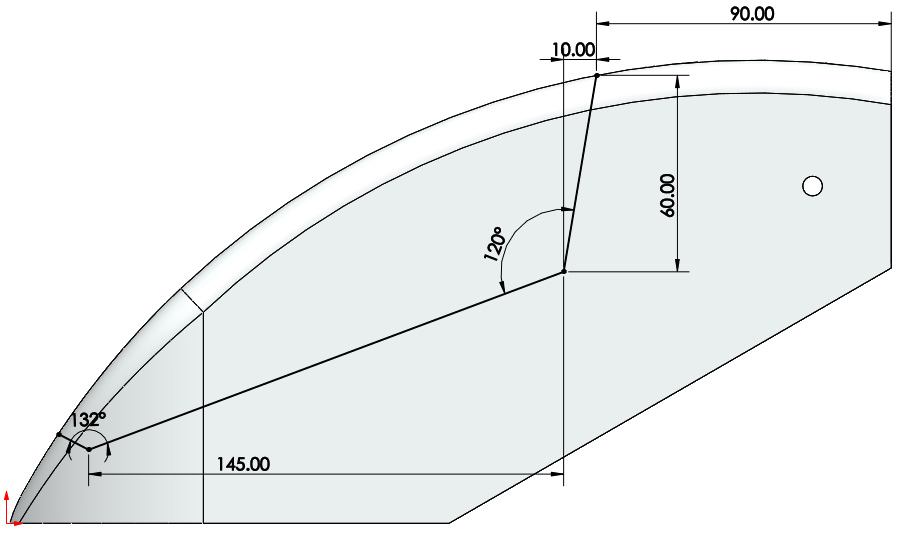
Figure P2.52 – A sketch can be used to split bodies

Figure P2.53 – The location of the split command
- Under the Trim Tools file, select the cut sketch we created in step 1, and then click on Cut Part. This will create two Resulting Bodies under that title. Check the two bodies, and then click on the green check mark. The sequence is highlighted in the figure below:
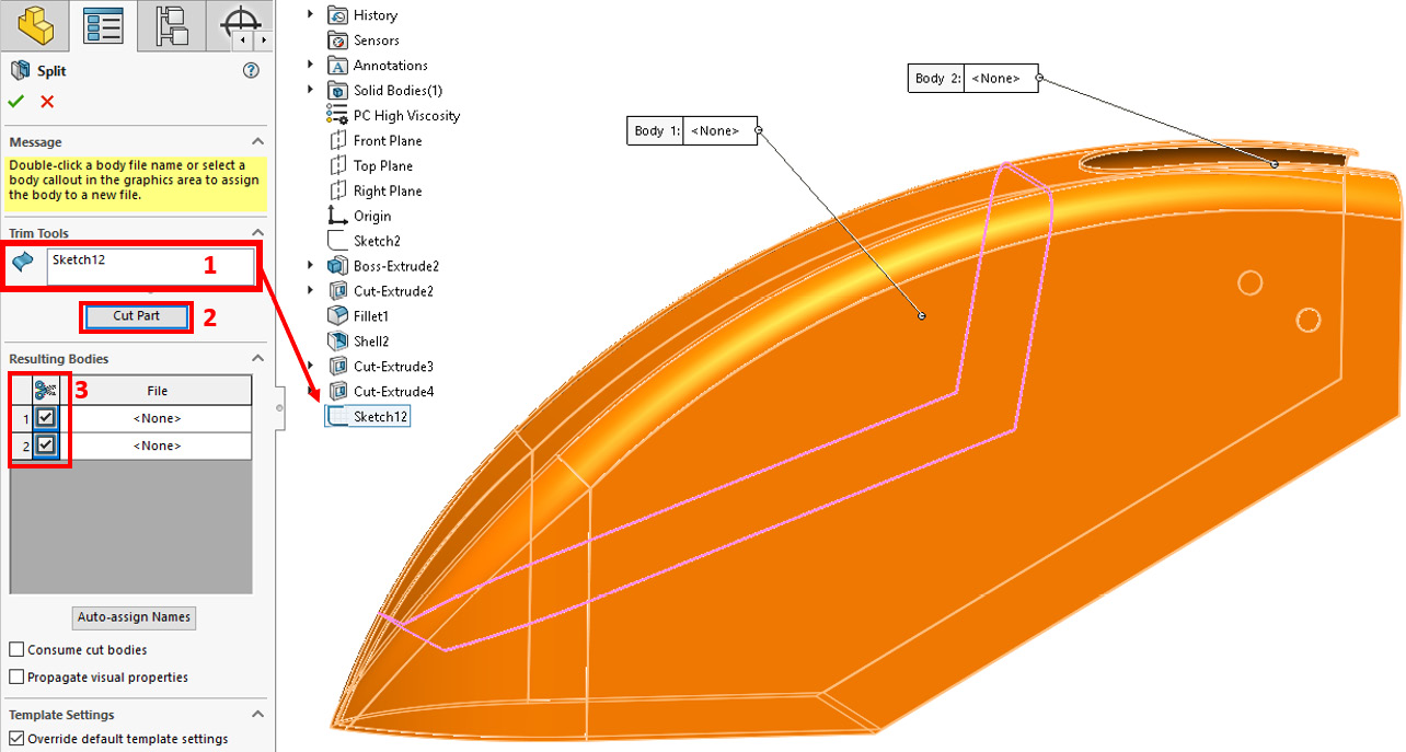
Figure P2.54 – The settings used for the Split command
Important Note
Giving names to the files in the PropertyManager, as shown in Figure P2.54, will save the named body in a separate part file.
At this point, we should have the body part complete like the one shown in the following figure. We can assign different materials and appearances to each body as we see fit:
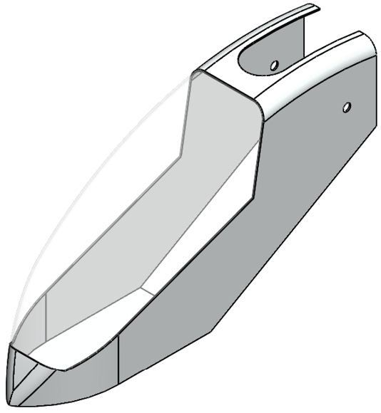
Figure P2.55 – The final body part
At this point, we are done 3D-modeling all the unique parts required for our RC helicopter model. Next, we will work on assembling the parts.
Creating the assembly
Now that we have all the parts 3D modeled, we can start exploring the assembly and start joining all the parts together. We will do that in this section. The following drawings highlight the fully assembled RC helicopter model:
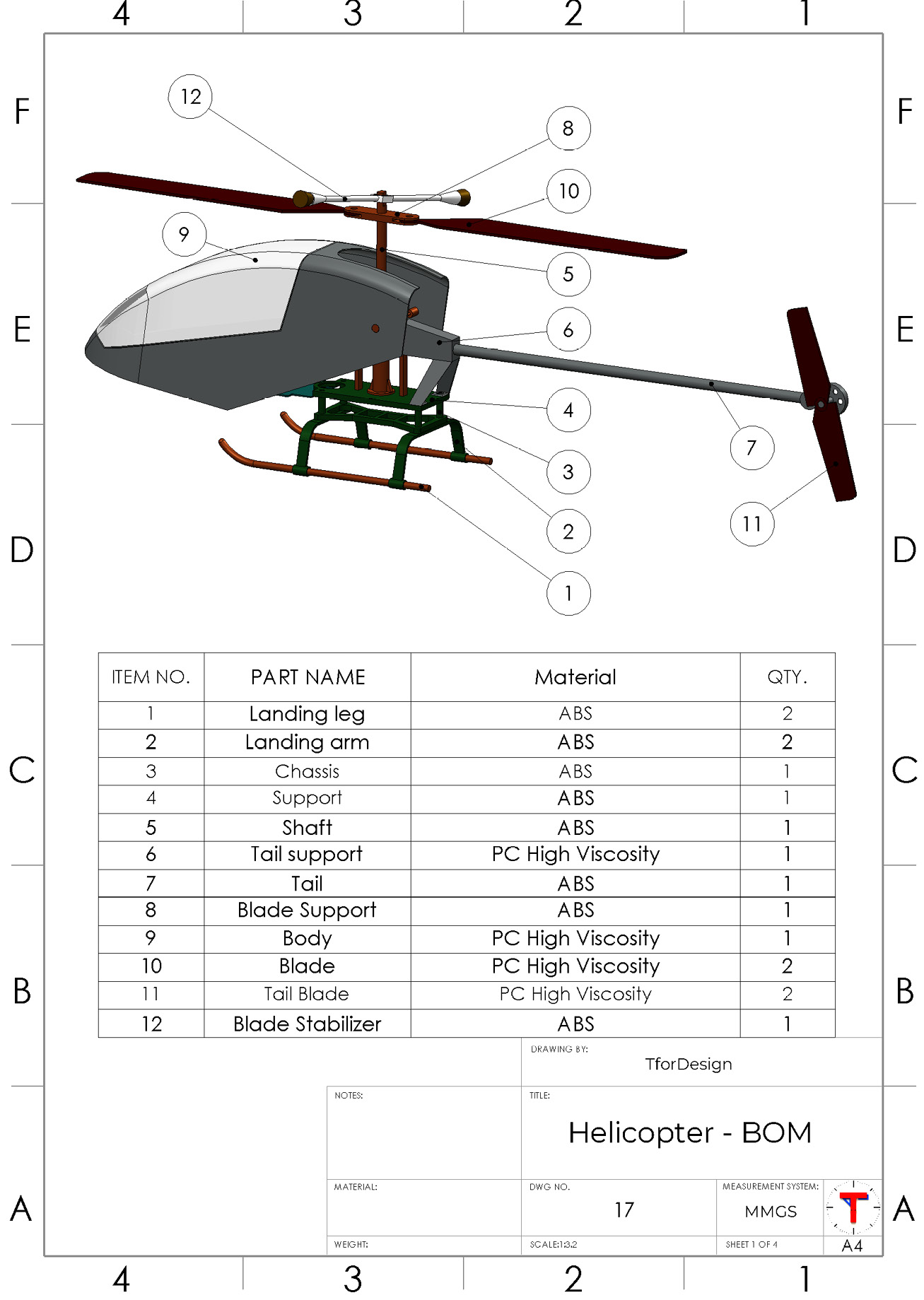
Figure P2.56 – The fully assembled RC helicopter model with all the parts
Let's explore more drawings that showcase different mates within the assembly. The following drawing highlighted the connections between the shaft and the support. It also shows the relation between the tail support and the support parts. Note that it also highlights an additional hole created in the context of the assembly:

Figure P.57 – Drawing showing the specific mates in the assembly
The following drawing shows an exploded view of the RC helicopter as well as the selected mates. It also highlights an additional cut in the landing arm that was made in the assembly context:
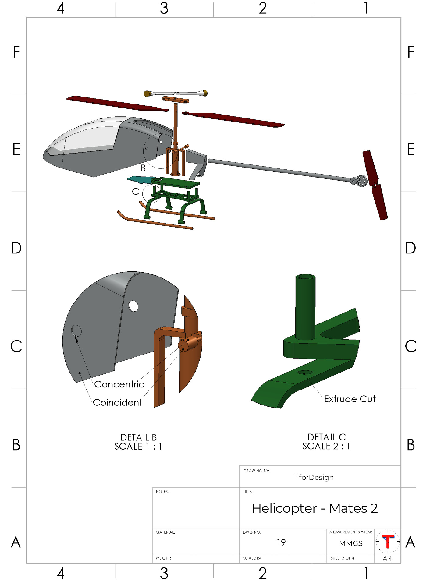
Figure P2.58 – An exploded view of the assembly
The following figure shows how the body part is angled with the chassis:

Figure P.59 – The body has an 8-degree angle with the chassis
The assembly figures explored previously contain all the major information needed to build the assembly. Note that not all the mates are specifically mentioned. Many of the mates can be concluded from the graphics of the overall assemblies. There are two different ways we can create the assembly, as follows:
- Adding all the parts in one assembly file
- Creating multiple subassemblies of fewer parts and then joining them together to form the larger assembly
In this text, we will follow the second approach. Let's explore some hints of one approach that can be adapted to build the assembly. Keep in mind that there is no one correct approach to generating an assembly such as this. Thus, treat the information presented as hints and food for thought. Feel free to adapt different approaches or experiment with them.
In the approach we are adapting, we will first build four smaller subassemblies, then join them to form the larger assembly. Each of the subassemblies we are building will consist of four or fewer unique parts. Building smaller subassemblies and then joining them to a larger one can help make them more manageable and easier to work with.
Important Note
A subassembly is an assembly file that is inserted into another larger assembly file.
The first subassembly consists of the landing leg and the landing arm, as indicated in the following figure. Overall, this subassembly consists of four parts, two of which are unique. The following figure also highlights the major mates used to build the subassembly:
Tip
You can experiment with using the linear pattern to build the shown subassembly.

Figure P.60 – The landing gear subassembly
The next subassembly consists of the support and the chassis, as shown in the following figure:

Figure P2.61 – The chassis subassembly
The next subassembly consists of the shaft, blade stabilizer, blade support, and blades, as shown in the following figure. We can set the shaft as the fixed part for this subassembly, as it is not a dynamic part in the final assembly. The following figure also highlights the selected mates that we can apply in the assembly:

Figure P2.62 – The blades subassembly
The last subassembly consists of the tail support, tail, and tail blade, as indicated in the following figure. Overall, this subassembly consists of four parts, three of which are unique. The following figure also highlights the major mates used to build the subassembly. We can pick the tail support as the fixed part for this subassembly, as it is a non-moving part in the final assembly:

Figure P2.63 – The tail subassembly
At this point, we can create a new subassembly that will join the four subassemblies together with the body. The following figure highlights the major mates connecting the different subassemblies with the main RC helicopter body. You can revisit Figure P2.56 to Figure P2.59 explored earlier for more information about how the different parts in the assembly interact with each other:

Figure P2.64 – The body connecting with the other subassemblies
By completing the assembly, you have completed the project work of 3D-modeling an RC helicopter. As additional activities, you can use different evaluation tools such as interference detection to find undesirable interferences and adjust the design as applicable. You can also further customize the RC helicopter model to make it your own.
Summary
In this project chapter, you worked to 3D-model an RC helicopter toy model. To achieve that, you had to interpret engineering drawings, 3D-model different parts, and then join them together in an assembly. The skills you used to construct this project include many advanced features often used by professional users; those include working with multibody parts, building configurations, using design tables, advanced mates, and assembly features. In the process, you have also constructed a project that can be included in your personal portfolio to highlight your 3D-modeling skills.
Congratulations on making it to the end of this book! This book was meant as a journey to build you a strong foundation in using SOLIDWORKS for 3D modeling. This foundation is the beginning of a new journey, whether you use the tools we explored in your next project or continue learning in more specialized areas such as surfacing, molding, weldments, drawings, sheet metals, or simulation. 3D modeling is a skill, just like any other; the more you use it, the better you will get at it, and the more you will develop your own style and a set of preferred tricks and shortcuts in the process. So, keep practicing, keep growing, and keep having fun in the process.