
Chapter 13: Equations, Configurations, and Design Tables
In this chapter, we will cover how to use equations, configurations, and design tables. These functionalities are not used to directly add or remove materials or features, such as an extruded boss, ribs, and sweeps. Rather, we will cover how to link different lengths with equations and how to generate multiple versions of a part using configurations and design tables. Mastering these functionalities will enable us to generate more interlinked models that are more robust and easier to modify. Also, it will enable us to generate multiple model versions for testing and evaluation.
The following topics will be covered in this chapter:
- Understanding and applying equations in parts
- Understanding and utilizing configurations
- Understanding and utilizing design tables
By the end of this chapter, we will be able to link different dimensions with equations and create multiple variations of a part within one SOLIDWORKS file. This will enable you to both optimize and accelerate your design process. Note that, in this chapter, we will focus on applications within part files. Similar functions are also available within assemblies.
Technical requirements
This chapter will require access to SOLIDWORKS and Microsoft Excel software on the same computer.
Check out the following video to see the code in action: https://bit.ly/3ytbT7j
Understanding and applying equations in parts
When creating 3D models, we often use a variety of dimensions to define sketch entities, such as squares and arcs. We also use dimensions to define features such as an extruded boss, an extruded cut, a revolved boss, and a revolved cut. In many applications, these dimensions are not isolated from each other. Rather, they are connected with mathematical relations. For example, the length of a rectangle should be 75% of its width or the height of a cylinder should be double the length.
In this part, we will learn how to set up these relations with equations. First, we will explain the equations, and then we will apply equations in the modeling of a SOLIDWORKS part.
Understanding equations
Equations within parts allow us to both define and link different dimensions together within the parts. By defining variables and equations, we will be able to build a more interconnected 3D model. This will give us certain advantages, such as the following:
- There will be ease in accessing specific defined dimensions, making them easier to adjust, as we can access those dimensions from the equations panel rather than by looking up the dimension from the design tree.
- There will be ease in modifying connected dimensions as equations will enable us to modify one dimension and have all other linked dimensions updated accordingly rather than modifying each dimension separately.
To theoretically demonstrate equations in the SOLIDWORKS part context, we will look at the rectangular cuboid scenario highlighted in Figure 13.1. Let's assume we were required to model a rectangular cuboid with the following specifications:
- A width equal to 5 millimeters
- A depth that is double the width (which equals 10 millimeters)
- A height that is 3 millimeters longer than the width (which equals 8 millimeters)
According to the given specifications, we can look at defining the rectangular cuboid dimensions in two different ways. The first is what we did previously using numerical values, and the other is using equations. The following screenshot highlights both methods; the rectangular cuboid on the left highlights directly inputting Numerical Values, while the one on the right highlights inputting Equations:
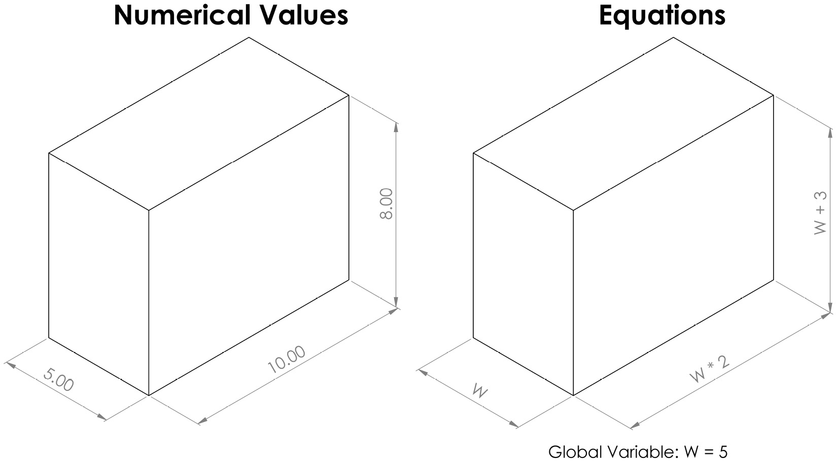
Figure 13.1 – A rectangular cuboid built in two methods
The initial final result of both methods gives the exact same cuboid. However, the way the dimensions are defined is different. Let's assume that, after creating this cuboid, we were required to adjust the width from 5 mm to 8 mm. With equations, all we will need to do is to change the W global variable from 5 to 8, and then all of the other dimensions for depth and height will change accordingly. However, if we input numerical values, we will have to change all three dimensions individually. This is why mastering equations is key when building more connected models.
Now that we know what equations are in a part modeling context, their advantages, and how they work, we can start learning how to use equations to enhance our 3D-modeling process.
Applying equations in parts
To demonstrate how to use equations when modeling parts, we will create the following simple rectangular cuboid with the variables shown in the screenshot:

Figure 13.2 – The rectangular cuboid we will create in this exercise
To start, we will define our global variables. To do this, follow these steps:
- Open the equations manager by right-clicking on the part name on the top of the design tree, and then choose Hidden Tree Items | Equations | Manage Equations..., as highlighted in the screenshot:

Figure 13.3 – The location of the equations manager
Tip
You can also go to equations by going to Tools and then Equations.
- Input the W and H variables under Global Variables and input the values, as highlighted in the screenshot. Click OK after defining the variables:
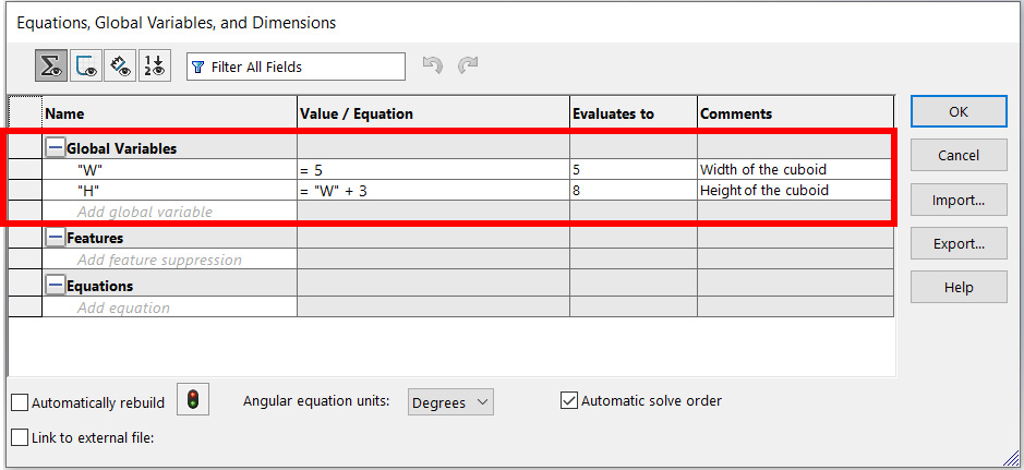
Figure 13.4 – Global variables are active through the model
- Verify that the variables are already defined by checking the new folder in the design tree under the Equations name, which will show all of our variables. The following screenshot highlights the new Equations folder:

Figure 13.5 – The defined variables are listed in the design tree
- Start creating our rectangular cuboid by inputting the variables instead of the lengths. When dimensioning the width, we can input ="W" instead of the number 5, as shown in the screenshot. Note that the dimension will then show as ∑ 5.00 to indicate the involvement of the function of the equation:
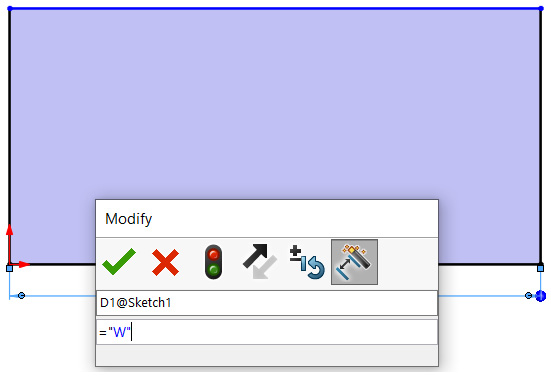
Figure 13.6 – Inputting the variable in the smart dimension field instead of the dimension
- Dimension the depth by inputting ="W"*2, as shown in the screenshot. Similar to the width, the depth dimension will be displayed as ∑ 10 to indicate the involvement of the equation function:
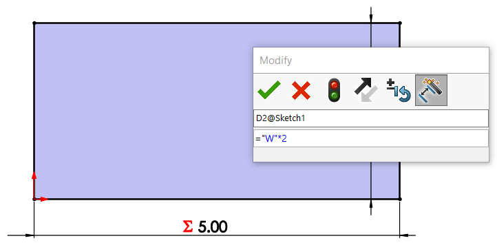
Figure 13.7 – Inputting the multiplication with a variable in place of the dimension value
- Apply the extruded boss feature; we can follow the same technique. When specifying the dimension, we can input ="H", which will result in the value 8, as highlighted in the screenshot:
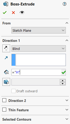
Figure 13.8 – Inputting the defined variable in the PropertyManager feature instead of the value
After applying the Extruded Boss feature, we will have the complete rectangular cuboid, as shown in the following screenshot:

Figure 13.9 – The resulting rectangular cuboid
Note that we can define our variables using any term we want. It can be a single letter or a word. A good practice is to use a term that would make it easier for us to recall while creating the model.
Now that we know how to apply equations, let's examine how easy this will make implementing modifications.
Modifying dimensions with equations
To illustrate how to modify dimensions, let's change the width (W) from 5 millimetres to 8 millimetres. To do this, we can follow these steps:
- Open the Equations Manager, which we will be able to find by right-clicking on the Equations folder in the design tree.
- Change the value of the W global variable from 5 to 8, as shown in the following screenshot, and then click OK:
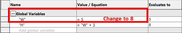
Figure 13.10: Changing the variable's value from the Equations Manager
After implementing this change, we will notice that all of the dimensions linked to the W variable have changed as well. In this, the height, H, changed from 8 to 11 and the depth changed from 10 to 16. Not only do equations allow us to change our dimensions faster, but they also allow us to keep the design intent while doing so.
Before we cover more in the next topic, let's examine a couple of more notes when dealing with equations. One is regarding the Equations Manager and the other is regarding design intents with equations.
Equations within the Equations Manager
If we go back to the Equations Manager, we will notice a tab at the bottom titled Equations, as highlighted in the following screenshot:
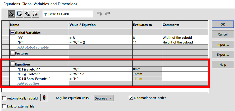
Figure 13.11 – Used equations are listed in the Equations Manager
This shows all of the equation applications we have in the model. It also gives us quick access to all of them in case we need to apply any change without needing to look up the actual feature in the design tree. The first column shows the names of the dimensions. For example, D1@Sketch1 refers to dimension 1 from Sketch1, which is listed in the design tree.
You may think that it is not convenient for us to recognize these codes (for example, D1@Sketch1), especially when we build models that contain many different measurements and sketches. To make this process easier, we can change these names as we are inputting the dimensions. The following screenshot shows the dialog box we get when we enter a specific dimension, highlighting where we can change the name of that specific dimension. The following highlighted box will enable us to change D1. To change @Sketch1, we can rename the sketch entry found in the design tree:

Figure 13.12 – We can change the name of the dimension as we are inputting it
Now, let's elaborate a bit more about design intent when using equations.
Design intent with equations
One important note to keep in mind when working with equations is the design intent. Whenever we 3D-model anything in SOLIDWORKS, we have to keep in mind the design intent we are aiming for. For example, if we are to sketch a rectangle with a width of 5 mm and a length of 10 mm, one question is, should we link the two dimensions with an equation?
To answer this, we have to ask ourselves what is important. If we intend to always have the length of the rectangle double the width, then applying an equation stating that would be the better practice. However, if we intend to have the length as 10 mm regardless of the width's value, then entering a direct numerical value would be the better practice. Referring to Figure 13.13, the rectangle on the left shows the dimensions input if our priority is to keep the length as double the width, while the rectangle on the right shows the dimensions input if our priority is to keep the length as a constant value:
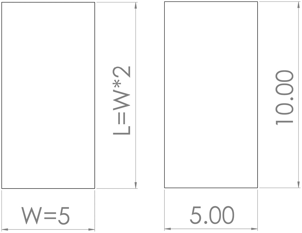
Figure 13.13 – Equations can help us preserve design intent
The rectangle example is a very simple one. However, the same principle is applicable for more complex parts or multiple parts linked together.
This concludes the topic of equations. We learned what equations are, how to apply and modify them, and, finally, important considerations with design intent and equations. Now, we can move on to exploring what configurations are within SOLIDWORKS parts modeling.
Understanding and utilizing configurations
Oftentimes, when creating a product, we will create multiple versions of it, with each of the versions having a slight variation from the others. SOLIDWORKS provides special tools for such configurations. In this part, we will learn all about configurations and how to use them to create different variations of a certain product or object.
What are configurations?
Configurations are different variations of a particular product or object. These variations would have small differences when compared to each other. For example, the four drawings in the following figure show different configurations of the same object:
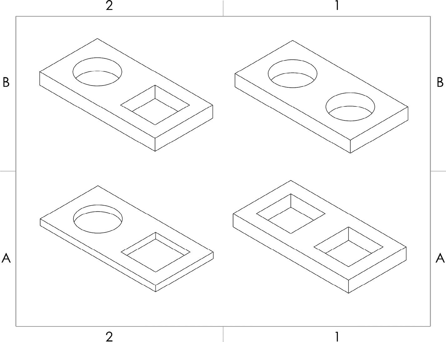
Figure 13.14 – Different configurations of the same object
Note that the four configurations do not have major differences from each other. Because of this similarity, it is an advantage for us to be able to create all of the different configurations in one SOLIDWORKS file rather than having a separate file for each configuration.
Now that we have a better idea of configurations, let's start applying them in SOLIDWORKS.
Applying configurations
Whenever dealing with configurations, we can start by creating a base model, and then we can create configurations of the base model. To highlight the application of configurations, we will create the model and the configurations highlighted in Figure 13.15. To make the exercise easier to follow, the dimensions in bold refer to dimensions that are different from one configuration to another:

Figure 13.15 – The 3D model we are creating in this exercise
To complete this exercise, we will follow these steps:
- Create a model titled Default Configuration, as highlighted in the preceding drawing. You can follow the procedure highlighted in the following screenshot for your first extrusion. Note that the circle is at the center of the rectangular face:
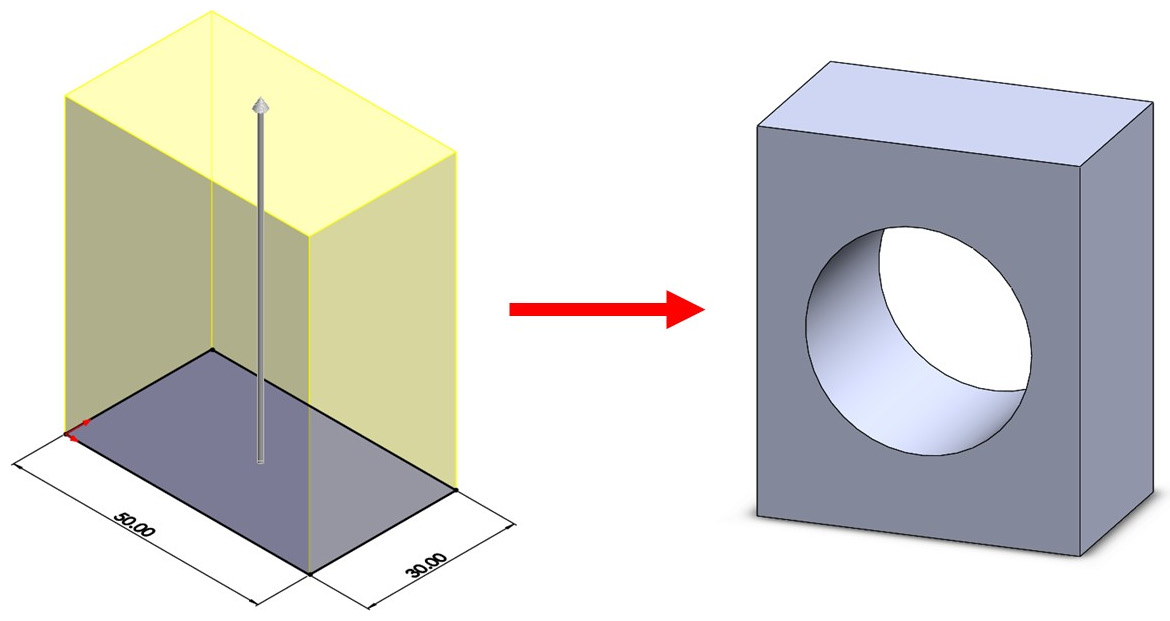
Figure 13.16 – The steps for creating the default configuration
- To start creating the first configuration, we have to add it by going to the ConfigurationsManager at the top of the design tree, and then right-clicking on Configurations and selecting Add Configuration..., as shown in the following screenshot:
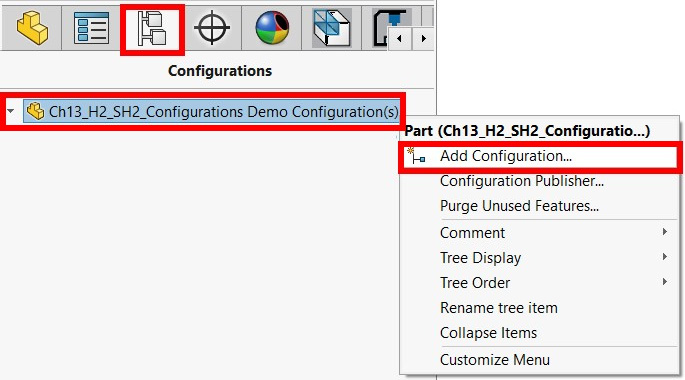
Figure 13.17 – The location of the Add Configuration… command
- After doing that, we will be prompted to enter a name in the Configuration name field as well as a small description in the Description field, as highlighted in the screenshot. We are free to choose a name and description that would help us to identify the configuration. Click on the green check mark to introduce the configuration:
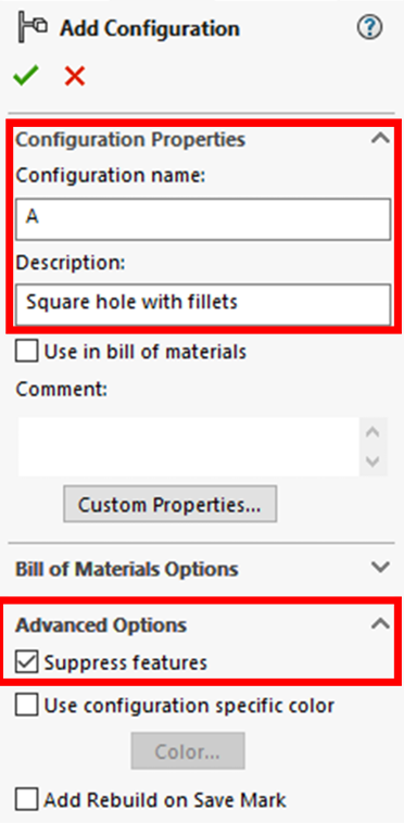
Figure 13.18 – Naming and describing the configuration can help us identify it later on
Important Note
The indicated Suppress features advanced option will have all-new features in the selected configuration that are suppressed in all other configurations.
- Note the different coloring on the Configurations list in the ConfigurationsManager. The active configuration will not be grayed out, as shown in the screenshot. Double-check that you are working in the A configuration. Then, go back to the design tree by clicking on the icon indicated with a square, as shown in the following screenshot:

Figure 13.19 – Available configurations are listed in the ConfigurationsManager
- Now, we can modify our model to match the A configuration given on the initial drawing. To do that, we will do the following:
- Suppress the Extruded Cut feature by right-clicking on the feature from the design tree and selecting Suppress.
- Implement a new extruded cut and the Fillet features to create the square extruded cut, as highlighted in Figure 13.15. Note that the square is at the center of the rectangular face. We should have the model shown in the following screenshot, which presents the A configuration:

Figure 13.20 – The 3D model for the A configuration
Tip
After creating new configurations, a good practice is to go back to the Configuration Manager and double-check the status of other configurations. In this case, in the ConfigurationManager, double-click on the Default configuration to check the difference and ensure that we created the new configuration successfully.
- Repeat steps 2–4 to generate the B configuration.
- Modify the model to match the B configuration, given in the initial drawing. To do that, we can do the following:
- Suppress the Fillet feature that we applied previously from the design tree.
- Edit the Extruded Boss feature (height) by changing the dimension to 40 mm. Also, ensure the change is applied only to This configuration by selecting the option from the PropertyManager, as shown in the screenshot:

Figure 13.21 – Specifying the related configuration when changing an existing feature's dimension
- Modify the depth by modifying the dimension in the initial sketch from 30.00 mm to 20.00 mm. Make sure this modification only applies to This Configuration, as shown in the following screenshot:

Figure 13.22 – Specifying the applicable configuration when adjusting a sketch dimension
- Go back to the ConfigurationManager and double-click on each of the configurations to double-check that they were applied correctly. At this point, our three configurations should be as they were in the initial drawing.
Important Note
When editing a dimension within an existing feature or a sketch, SOLIDWORKS allows us to pick which configuration this change should apply to. For example, in the exercise, we applied all of our edits to only the active configuration by selecting the This Configuration option. We can also choose to apply the edits to All Configurations or specify which configurations we want the edits to apply to.
This concludes this exercise in creating different configurations for a specific model. Remember that it is a good practice to go back to the ConfigurationManager and double-check that all of our configurations are accurate by double-clicking on each of them. Here are some important takeaways from this section:
- We can suppress and un-suppress features to set them to different configurations.
- When modifying dimensions on existing features or sketches, we have to select the scope in terms of which configuration(s) the adjustment will apply to.
Now, we can start working with design tables, which is another method that will enable us to create different configurations.
Understanding and utilizing design tables
Through configurations, we were able to create different variations of a particular 3D model. Design tables will also allow us to create different variations of a 3D model. However, unlike directly setting up configurations, design tables will enable us to generate more than one variation at the same time instead of generating them one after the other. In this section, we will cover how to set up design tables and some scenarios in which design tables will give us an advantage over directly setting up configurations.
What are design tables?
Design tables are one method that will enable us to create multiple variations of a specific 3D model at once. Design tables make it easy and efficient to set up different dimensions for lengths and angles. They also allow easy manipulation for suppressing certain features in specific model variations or configurations. The following drawing highlights a simple application of a design table with the multiple configurations it generates. Note that, with design tables, we do not enter the dimensions for the different configurations manually one by one.
Rather, we just enter a table highlighting how the different configurations will differ, and SOLIDWORKS will then generate all of the configurations at once. In the following screenshot, all the configurations are different, based on the three Length, Width, and Thickness parameters only:

Figure 13.23 – Design tables enable us to quickly create different variations of a model
When working with design tables, a good practice is to start by creating a base model that includes all of the dimensions and features we will vary on other configurations. It is also a good practice to make custom names for all of the dimensions and features we want to vary for easy identification. Now that we have an idea of design tables, we can start applying them when creating models.
Setting up a design table
When dealing with design tables, we can start by creating a base model. After that, we can use a design table to create multiple configurations. This will be the process we follow in this exercise: creating the base model and using the configurations highlighted in the following diagram. SOLIDWORKS uses Microsoft Excel to generate design tables, so you must have Microsoft Excel installed on your computer to use design tables:
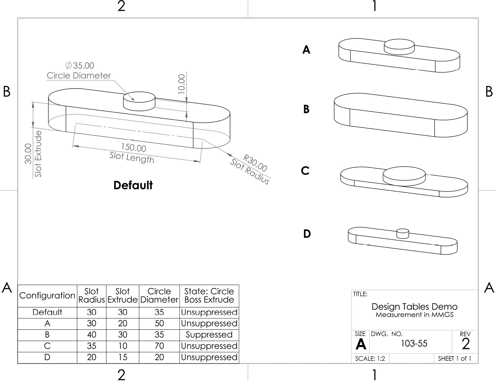
Figure 13.24 – The drawing for the design table's exercise
To create the following model utilizing design tables, follow these steps:
- Create the base model, as highlighted in Figure 13.25. When doing that, you can use the following good practices. They will minimize confusion when generating and using a design table:
- Give names to your dimensions as you are inputting them. The following screenshot shows inputting the name for Slot Radius. You can follow the naming, as shown in Figure 13.26:

Figure 13.25 – Naming the dimensions can help identify them easie
- Rename your features and sketches listed in the design tree to make them easy to identify. The following screenshot highlights a sample of renamed features and sketches for use in this exercise. Note the names are as shown in Figure 13.27:

Figure 13.26 – Naming the features can make them easier to identify
- To add a design table, go to Insert, then Tables, and select Design Table..., as highlighted in the following screenshot:

Figure 13.27 – Inserting a design table
- Select the source as Auto-create, as in the following screenshot. Edit Control is set by default to Allow model edits to update the design table; we will leave that selected. We will discuss this option later in this section. Click on the green check mark to initiate the design table:
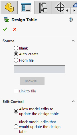
Figure 13.28 – The initial options for generating a design table
- Select the dimensions we want to vary, as shown in the following screenshot. Note that this selection only includes dimensions related to sketches and features, not whether a feature is applied or suppressed. Also, note how naming the dimensions and features make them easier to identify:

Figure 13.29 – We can select the dimensions to be inserted into the design tree
- Fill in the design table, as highlighted in the following screenshot. The first column in the table shows the name of the configuration, while the others show dimensions unique to that particular configuration. Note that empty cells will automatically take the values of the active default configuration:

Figure 13.30 – We can input all our variations directly in the design table
- The table only has dimensions so far. However, the B configuration has the Circle-Extruded Boss features suppressed. To add the state of the feature to the design table, select the first empty title cell, and then double-click on the feature on the design tree, as highlighted in Figure 13.32. This will automatically add the state of the feature to the design table.
- To adjust the status of the feature, we can type the letter U for unsuppressed or the letter S for suppressed. Alternatively, we can type the full words (unsuppressed or suppressed) or 0 and 1, which stand for unsuppressed and suppressed respectively. Adjust the feature status, as shown in the following screenshot:

Figure 13.31 – We can indicate the state of a feature in the design tree
Tip
We can also add any dimension to the design table by directly clicking on it from the sketch on the canvas, similar to adding the feature status.
- Click anywhere on the canvas outside of the table to confirm the table. We will see the following message, confirming the new configurations:
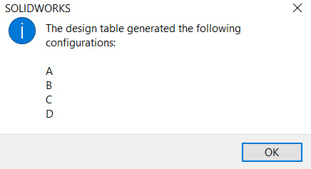
Figure 13.32 – A conformation message after generating the design table
After generating the different configurations, it is a good practice to double-check them. So, go to the ConfigurationManager and check all of the configurations that we just generated, and note how they are different from each other.
This concludes our coverage of how to generate a design table to create multiple configurations. However, now that we know how to initiate a design table, we will also learn how to edit it.
Editing a design table
There are two ways in which we can edit or update our design table. The first one is through the design table itself and the other is through directly modifying the dimensions in the model. We will examine both ways.
Editing directly from the design table
To edit the design table, we can find it on the ConfigurationManager. Then, right-click on the table and select Edit Table, as shown in the following screenshot:
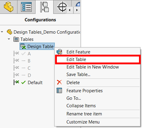
Figure 13.33 – The edit table command for design tables
After selecting the Edit Table command, the table will open for us to modify as we see fit. After modification, we can simply click anywhere on the canvas for all of the modifications to be applied.
Editing the design table by modifying the model
Another way of editing the design table is by directly editing the model by editing sketches or features from the design tree. This will update the corresponding cells in the design tree. However, this will only happen if we select the Allow model edits to update the design table option for Edit Control, as shown in Figure 13.35. Recall that we selected this option when we were creating the table. We can adjust this option by right-clicking on the design table from the ConfigurationManager and then selecting Edit Feature:
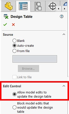
Figure 13.34 – Manual 3D model edits can automatically update the design table
Note that applying a design table does not prevent us from adding additional configurations, as we explored in a previous section when discussing configurations. We can use both methods together as we see fit.
This concludes this section about design tables. We covered what design tables are and how to apply and edit them. Design tables are a very efficient method that enables us to generate multiple configurations at once and are an essential tool for SOLIDWORKS professionals.
Summary
In this chapter, we learned skills that will enable us to create more robust and agile models. We covered equations that will enable us to create more connected models to help us to deliver our design intents. We also learned how to create different configurations of a specific model. We learned how to do that by directly and manually adding and adjusting configuration, or by using design tables to accomplish a similar objective.
The new skills in this chapter will enable us to generate more connected models. They will also enable us to generate many different variations of a model in a single SOLIDWORKS file. These will enable us to more efficiently conduct variation testing and quicker adjustments, which were the goals of this chapter.
In the next chapter, we will cover advanced mates within assemblies, which will help us to create assemblies with parts that have more complex interactions between each other.
Questions
The following questions will help to emphasize the main points we have learned in this chapter. However, in terms of practical exercises, do not limit yourself to what we provide you with here. Try modeling random objects around you or come up with your own innovative mode to increase your fluency using the software:
- What are the equations when modeling parts? Why do we use them?
- What are the configurations for a specific part?
- What are design tables?
- Create the model shown in the following screenshot, utilizing global variables and equations:
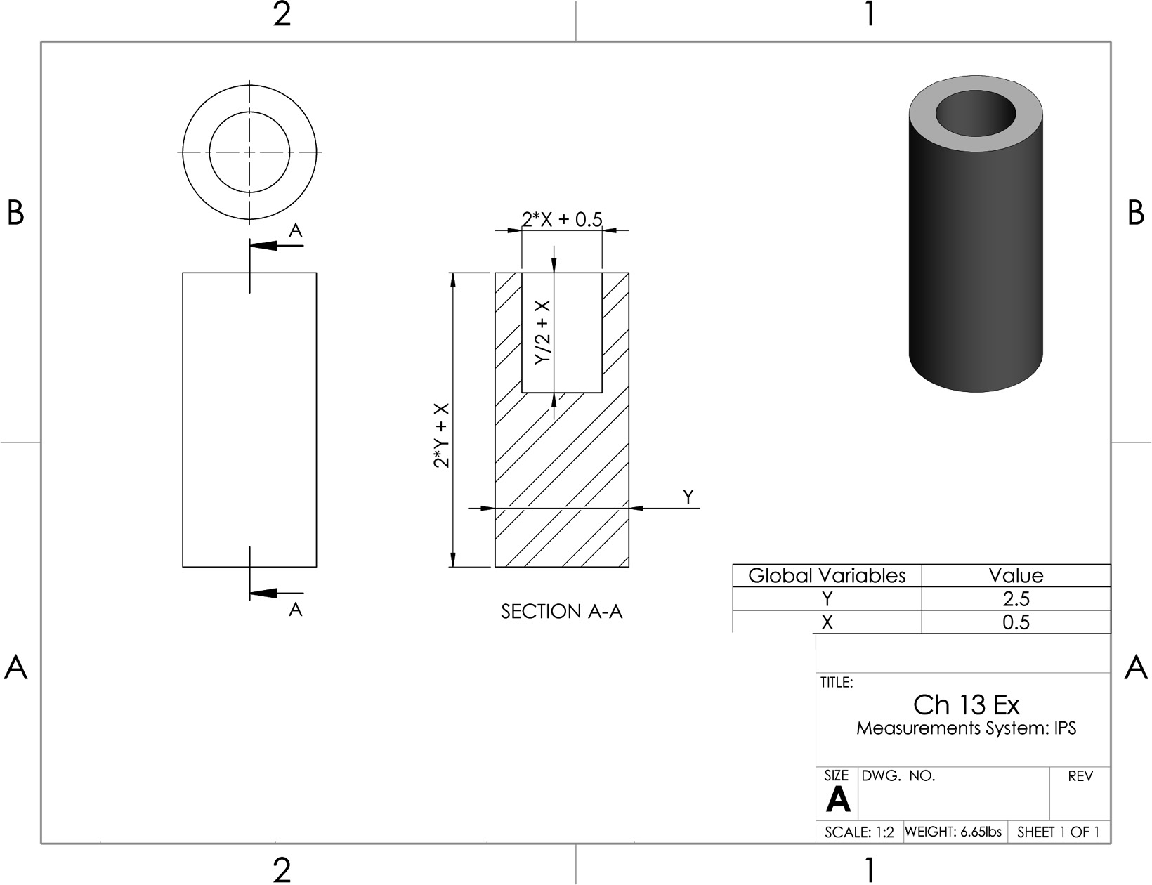
Figure 13.35 – The drawing for question 4
- Create the base model shown, including the different configurations it highlights. Note that the two squares and the two circles in the A and B configurations are mirrors of each other:

Figure 13.36 – The drawing for question 5
- Create the following model and the different configurations shown using design tables. Use the MMGS measurement system when completing this exercise:

Figure 13.37 – The drawing for question 6
- Create the following model and the different highlighted configurations. The model is displayed in two different screenshots to cover all of the requirements. Hint – use the mass values to double-check your model's accuracy:
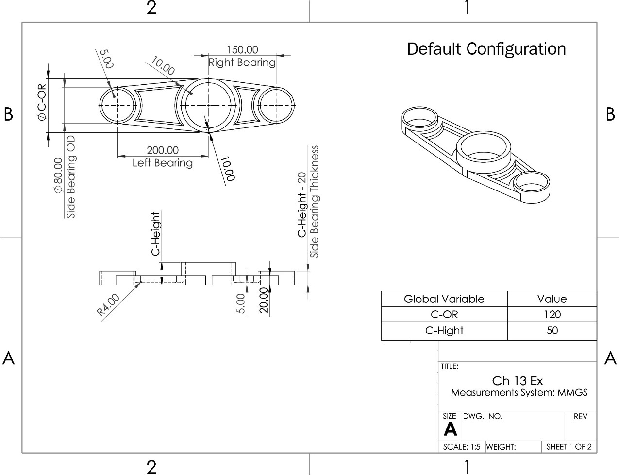
Figure 13.38 – The first drawing for question 7
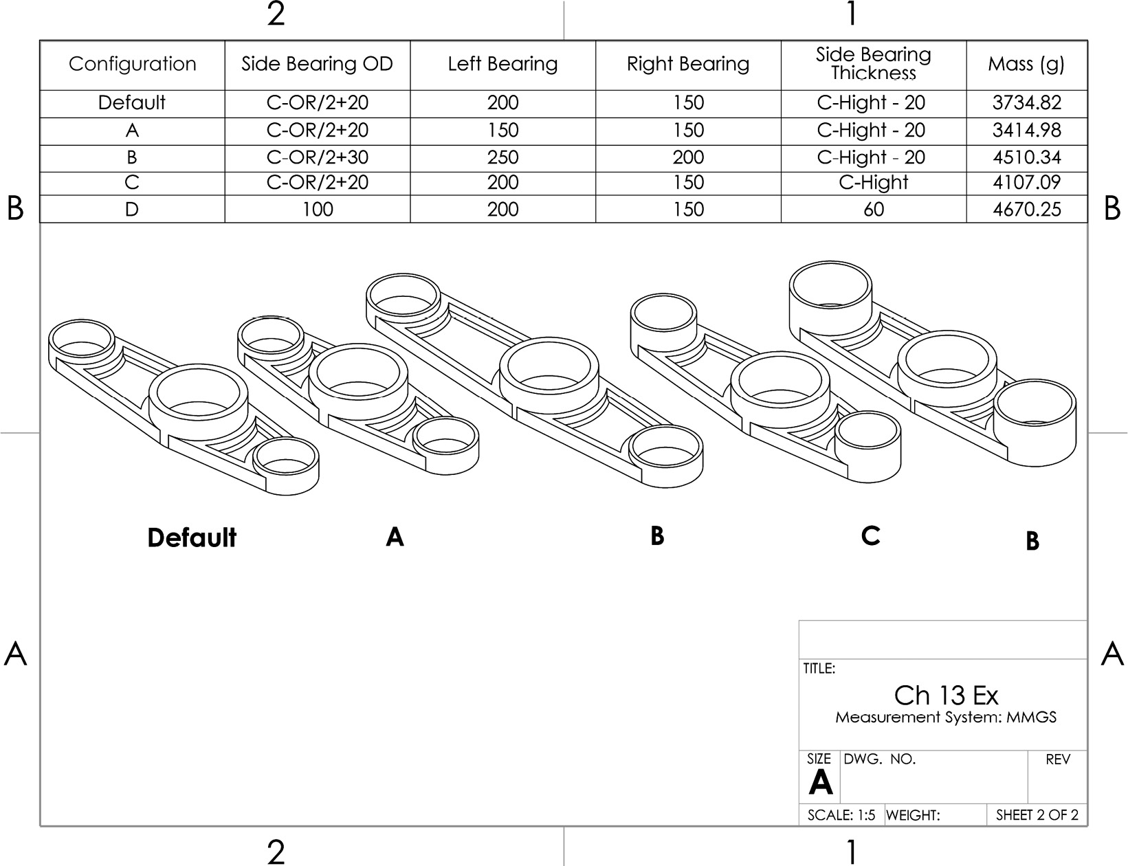
Figure 13.39 – The second drawing for question 7
Important Note
The answers to the preceding questions can be found at the end of this book.