
Chapter 12: Advanced SOLIDWORKS Mechanical Core Features
In this chapter, we will cover more advanced and less commonly used features in SOLIDWORKS mechanical modeling. These features include the draft feature, the shell feature, the Hole Wizard, features mirroring, and the rib feature. We will use these features to build models, while also covering multi-body parts. These features will greatly enhance your SOLIDWORKS skills to an advanced level by further simplifying complex model creation and manipulation. They are also essential for passing the SOLIDWORKS professional certification exam.
The following topics will be covered in this chapter:
- Understanding and applying the draft feature
- Understanding and applying the shell feature
- Understanding and utilizing the Hole Wizard
- Understanding and applying features mirroring
- Understanding and applying the rib feature
- Understanding and utilizing multi-body parts
- Understanding and applying the linear, circular, and fill feature patterns
By the end of this chapter, you will be able to generate more complex models with features matching international standards with holes. Also, the draft, shell, mirror, rib, and multi-body parts features will provide us with more means to meet specific design requirements.
Technical requirements
This chapter will require that you have access to the SOLIDWORKS software. The project files for this chapter can be found in this book's GitHub repository: https://github.com/PacktPublishing/Learn-SOLIDWORKS-Second-Edition/tree/main/Chapter12.
Check out the following video to see the code in action: https://bit.ly/323CkEt
Understanding and applying the draft feature
Drafting refers to changing sharp steps in parts into chamfered ones. Drafting primarily comes from the casting and plastic injection molding industry to make it easier to release parts out of molds. As SOLIDWORKS professionals, we will be expected to apply drafts to a variety of applications where necessary. In this section, we will explore what drafting is and how to use the draft feature.
What are drafts?
Drafts are commonly applied to parts that are made with injection molding. It is a slight tilt between two different surfaces at different levels. In practice, drafts help make parts fit better with the mold and make the parts easier to remove from the mold compared to without it. Also, drafts help increase the success rate of the mold taking effect.
The following diagrams highlight the effect of the draft feature. The first diagram shows the model at hand, as well as the Cross-section area we are applying to show the effect of the draft:

Figure 12.1 – An example of a draft
The second diagram shows the cross-section of the model With Draft and Without Draft. Note that the draft looks similar to a chamfer:

Figure 12.2 – Examples of a design with and without draft
Now that we know what drafts are, we can apply them to create a particular 3D model.
Applying drafts
In this section, we will cover how to apply the draft feature. We will apply a draft to the following model. You can download this model from the package provided for this chapter.
Alternatively, you can create the model from scratch. All of the lengths are in millimeters. Note that the draft is measured by the angle shown in the Draft DETAIL D view:

Figure 12.3 – The 3D model we will build in this exercise
To create the draft, do the following:
- First, download and open the model for this exercise. The model is as follows:

Figure 12.4 – The model to be downloaded for this section
- Select the Features command category, then select the Draft command, as highlighted in the following screenshot:
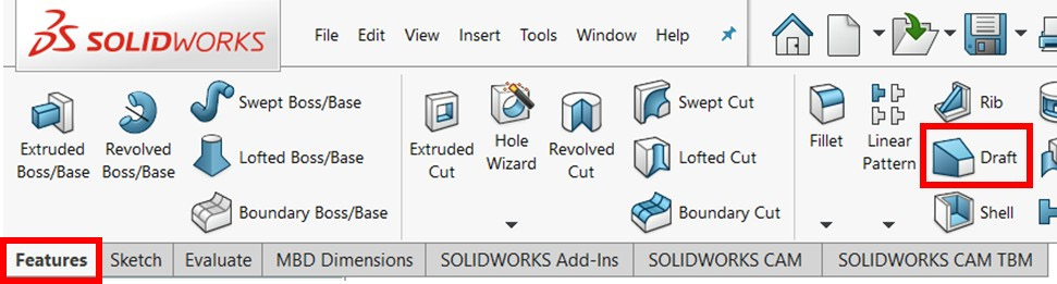
Figure 12.5 – The location of the Draft command
- Adjust the PropertyManager options and selections so that they match those shown in the following screenshot. Here is a brief description of some of the options:
- Neutral plane: Here, we can select a surface that will be adjacent to the draft. This neutral surface will remain unchanged during the creation of the draft. Hence, the other adjacent surface will be affected.
- Faces to Draft: Here, we can select all of the faces to be drafted. We can select more than one surface as we see fit. In this exercise, we are selecting all four inside faces:

Figure 12.6 – The settings for the draft feature
- Click on the green checkmark to apply the draft. The resultant draft will be as shown in the screenshot. In the applied draft, note the following:
- The position of the angle of the draft. In many instances, we might be given the complementary angle in a drawing instead of the draft angle. The complementary angle is 90 minus the given angle.
- The neutral surface and its surface area remained unchanged compared to all of the other surfaces related to the draft:

Figure 12.7 – The selected neutral surface remains unchanged once the draft has been applied
Note that, in this exercise, we used the Neutral plane draft type. Other types of drafts are available, including Parting line and Step draft, which can be created similarly. The following diagram highlights an example of a parting line draft application:

Figure 12.8 – A demo application of the parting line draft
The following diagram highlights an example of a step draft application:

Figure 12.9 – A demo application of a step draft
Both draft options can be found in the draft feature's PropertyManager. This concludes our coverage of the draft feature. We learned what the feature is and how to generate and define it.
Next, we will cover another feature known as the shell feature.
Understanding and applying the shell feature
In this section, we will cover the shell feature. As its name suggests, the shell feature enables us to create a shell out of an existing shape without much effort. In our everyday lives, we interact with shells in multiple products such as cans, laptops, and phone exteriors. In this section, we will explore what the shell feature is and how to apply it.
What is a shell?
The shell feature enables us to make a shell of an existing model. It makes it easy to create objects such as cans and containers. The following screenshot shows a box with the effect of the Shell command implemented:
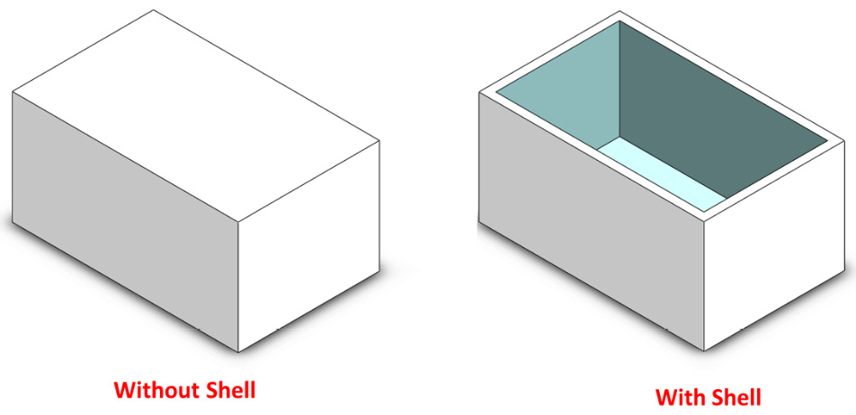
Figure 12.10 – The impact of the shell feature
Now that we know what the shell feature does, we can apply it to create a specific model, which we will do next.
Applying a shell
In this section, we will cover how to apply the shell feature. We will apply the Shell command to create the following model. You can download this model from the package provided for this chapter. Alternatively, you can create the model from scratch. Note that this is a continuation of the previous model. The thickness of the wall is 3 mm, as highlighted in the review cloud in the diagram:
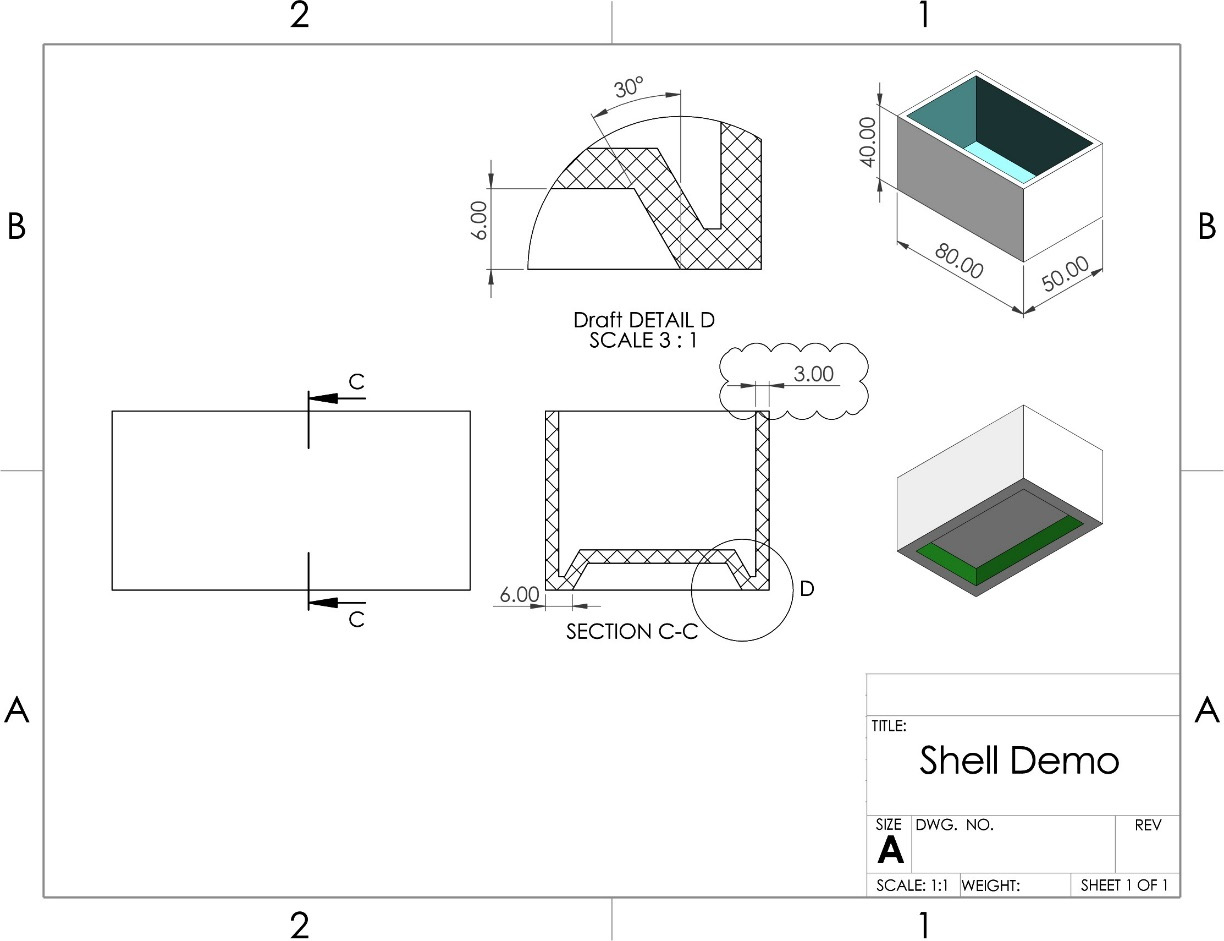
Figure 12.11 – The 3D model we will build in this exercise
To create the highlighted shell, follow these steps:
- First, download and open the model for this exercise. The model is as follows:
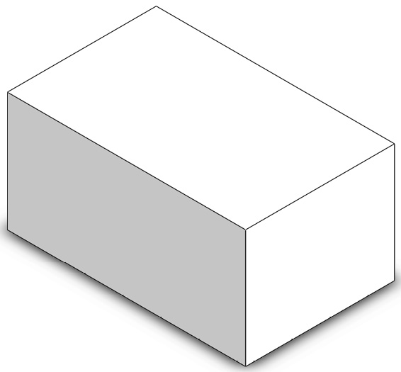
Figure 12.12 – The model that is included with the downloads for this section
- Select the Features command category, then select the Shell command, as highlighted in the following screenshot:
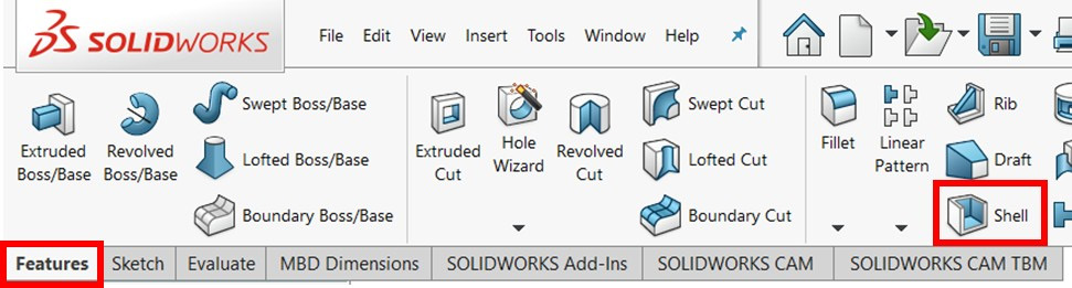
Figure 12.13 – The location of the Shell command
- Adjust the PropertyManager options and selections so that they match the parameters highlighted in the following screenshot:

Figure 12.14 – The selected face parameters will be removed after applying the shell
Here is a brief description of some of the options:
- Faces to Remove: This is the field below the thickness of the draft. The faces we select here will be removed after we apply the shell. If we leave this field empty, the model will still be shelled from the inside; however, the outer surface will remain unchanged.
- Shell outward: This will flip over the shell direction. In other words, the current model will be removed and replaced by a shell starting from its outer surface. You can give it a try to figure out the effect.
- Multi-thickness Settings: This allows us to have different wall thicknesses on different sides. We will look at this in more detail in this section.
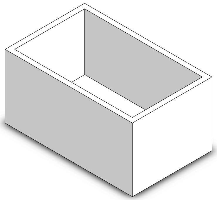
Figure 12.15 – The resulting 3D model after applying the shell feature
This concludes this section on applying a unified shell using the shell feature. Next, we will cover a special condition where we can specify different thicknesses for different sides.
Multi-thickness Settings
In the shell's PropertyManager, we have the option of making a shell with different thicknesses for different walls. To explore this option, we will go back to our model and modify it. This modification is highlighted by the review cloud in the following diagram:

Figure 12.16 – The multi-thickness shell we will apply
Note that the model is still shelled in the same way; however, two of the walls have different thicknesses than the others.
To apply this modification, we can do the following:
- Right-click on the Shell feature from the design tree and select Edit Feature.
- Via PropertyManager, we will adjust the fields under Multi-thickness Settings by doing the following. The following screenshot highlights Multi-thickness Settings:
- Under the Multi-thickness Settings face selection, select one of the faces we want to make thicker. Then, adjust the thickness from 3 mm to 6 mm.
- Select the other face and adjust the thickness again from 3 mm to 6 mm. Note that we have to adjust the thickness of each side separately. The rest of the faces will keep the default thickness we set at top of PropertyManager:

Figure 12.17 – The multi-thickness setting allows us to apply different thicknesses to the walls
- Click on the green checkmark to apply these Multi-thickness Settings. The result of the model will be as follows. Note that two of the side walls are thicker than the others:

Figure 12.18 – The resulting shell with multiple wall thicknesses
This concludes this exercise on using the shell feature. We covered the shell feature and how to apply it, as well as how to apply both shell thickness and a multi-thickness shell. In the next section, we will cover the Hole Wizard, which will enable us to create different types of holes.
Understanding and utilizing the Hole Wizard
Holes are very common features in most products. If we look at any project, we will likely see screws that hold different parts together. In essence, these are different holes. Usually, these holes are made according to common international standards. The Hole Wizard allows us to create holes as per those standards. In this section, we will explore the Hole Wizard and how to utilize it to create holes.
What is the Hole Wizard and why use it?
The Hole Wizard in SOLIDWORKS enables us to create holes in our model that match international standards for holes. This includes drilling and threading the holes as well. The Hole Wizard makes it easy and convenient to make those holes by selecting the hole standard and type and placing the hole directly on the part.
Identifying a hole in SOLIDWORKS
To identify a hole in the SOLIDWORKS Hole Wizard, we must have the following information about the software:
- Hole type: This includes the following:
- Overall shape: Nine shapes are supported by the Hole Wizard; these include counterbore holes, countersink holes, tapered tap holes, slots, and others. We have a graphical presentation of each hole shape in the SOLIDWORKS interface.
- Standard: This includes internationally recognized standards for defining holes. The most commonly used standards are the ones from the International Standard Organization (ISO) and the American National Standard Institute (ANSI). The Hole Wizard also includes more standards such as those from the British Standard Institute (BSI), the Japanese Industrial Standards (JIS), Korean Standards (KS), and many others. These standards mainly differ in holes sizes, hole fittings, and referencing.
- Type: The type of the hole depends on the preceding two options. Each combination of the overall shape and standard will have a different set of types to choose from.
- Hole specifications: This includes the following:
- Size: This allows us to specify the diameter of the hole, as per the standard and type we pick. Note that each standard references sizing differently in terms of naming.
- Fit: For selected hole shapes, we will be able to specify whether we would like to have a normal, loose, or close fit for our hole.
- Custom sizing: This allows us to further customize the size of the hole from the standard size if needed.
- End condition: Similar to the end conditions for the common features we used previously, this allows us to specify the depth of the hole. This will also allow us to specify the depth of the thread if the hole involves that.
We have just learned what the Hole Wizard is and what specifications we need to know about to identify and call out a hole. Next, we will learn how to put all of that into practice by using the Hole Wizard to create holes.
Utilizing the Hole Wizard
In this section, we will use the Hole Wizard to create multiple holes in a box, as shown in the following diagram. You can download the basic box from the models for this chapter. Alternatively, you can create it from scratch. Note that each of the holes is identified with all of the information we need to create it. All of the lengths in the following diagram are in millimeters.
The following diagram highlights the two holes that we will be creating:

Figure 12.19 – The 3D model we will build in this exercise
To make this, we will create Hole 1 and then Hole 2. Follow these steps to do so:
Note
The preceding diagram shows multiple holes that have been made with different standards. When working with a realistic project, we will only use one standard for the whole product. However, as this is an exercise for demonstration and learning purposes, we are using different standards.
- First, download and open the model linked to this section.
- Select the Hole Wizard command, as shown in the following screenshot:

Figure 12.20 – The location of the Hole Wizard command
- Making Hole 1: At this point, we will be making Hole 1, which will be in three stages – choosing the hole specifications, choosing the hole's position, and confirming the hole's position:
- Hole Specification: We can fill out the information shown in the preceding diagram. The settings will be as shown in the following screenshot. After deciding on the hole specifications, we can choose the hole's position. The hole's shape is only shown with figures; however, if we hover our cursor over the icons, the names will appear:

Figure 12.21 – The hole specifications can be applied to match the industry standards
- Hole Position: To start working on the positioning of the hole, we can select the Positions tap in PropertyManager. This will prompt us to select which surface we want the hole on. Select the bluish top surface, as highlighted in the following screenshot:

Figure 12.22 – Holes can be positioned on an existing surface
Then, we can place a dot, which will be the center of the hole. This hole is in the center of the shape, which coincides with the origin. Hence, we can place the dot so that it coincides with the origin, as highlighted in the following screenshot. Note that we can see a preview of the hole:
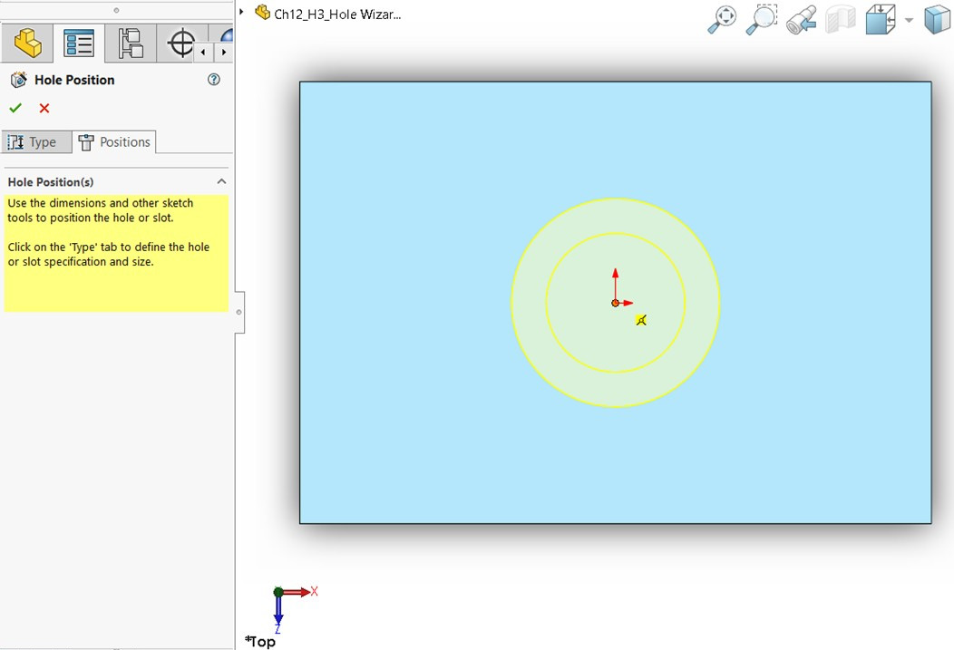
Figure 12.23 – A hole can be positioned using sketching commands
Note
If you don't select any surface for the Hole Wizard, a 3D sketch will be started to locate the hole. You can also click on the 3D Sketch option shown in Figure 12.22 if you intend to use a 3D sketch for positioning.
Tip
You can pre-select a surface to use with the Hole Wizard.
- Confirmation: If we are happy with the hole preview, we can click on the green checkmark to implement the hole. The hole will be added, as shown in the following diagram:

Figure 12.24 – The hole that matches the specified standards will be applied after confirmation
- Making Hole 2: To make the other holes, we will follow the same procedure we did for the first one. However, the specifications, the positions, and the number of holes are different:
- Hole Specification: The specifications for the second hole can be set like so:

Figure 12.25 – The specifications of the second hole's types
- Hole Position: Now that we have two holes, we can place two dots for each hole. Positioning a hole follows the same sketching commands we used previously. The only exception is that any point we place will be interpreted as a center of a hole. Hence, we can position our holes using the Smart Dimension command to match what's shown in the following diagram:

Figure 12.26 – Dimensions can be used to locate a hole
- Confirmation: Click on the green checkmark to apply the two holes. The final shape will look as follows:
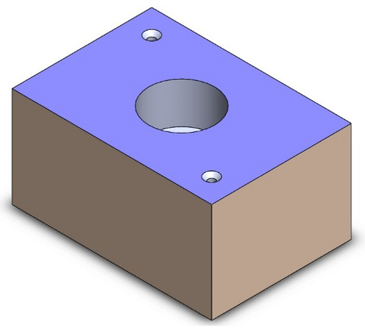
Figure 12.27 – The final 3D model after confirming the holes
This concludes how to utilize the Hole Wizard. In this section, we learned what the Hole Wizard is and how to identify details for the Hole Wizard. Then, we learned how to use the Hole Wizard's functions in SOLIDWORKS to generate a hole based on different industry standards and identifications. Next, we will cover how to mirror any feature we apply in SOLIDWORKS.
Understanding and applying features mirroring
Sometimes, we need to create a feature or a set of features and then try to duplicate them on the other side of the model. We can accomplish this by mirroring the features. In this section, we will discuss what mirroring is from a feature perspective. We will also learn how to use this feature to mirror other features.
What is mirroring for features?
Mirroring features works the same way as mirroring the entities of a sketch. It enables us to duplicate a feature or a set of features by reflecting them on a plane.
The following diagram highlights the effect of mirroring features. The model on the left highlights a model with a set of features, while the model on the right highlights the model after mirroring selected features:
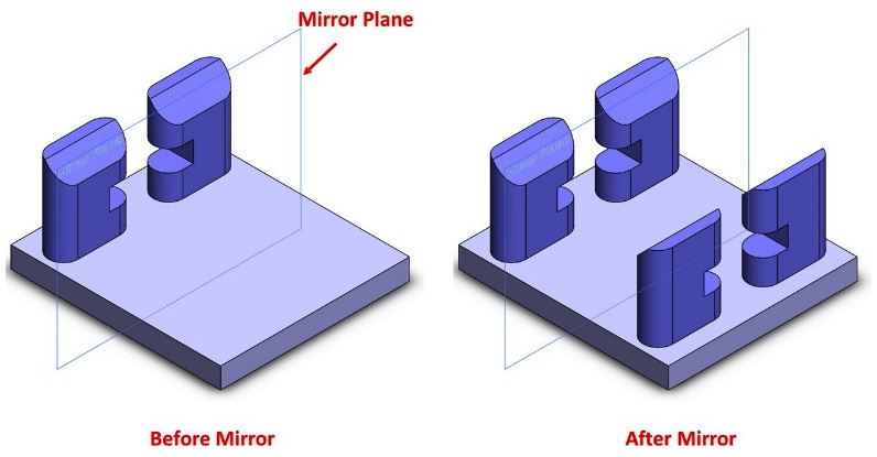
Figure 12.28 – The impact of the mirror feature
Now that we know what is meant by mirroring features, we can start learning how to apply the feature to 3D model creation.
Note
The mirror plane could be an existing plane or an existing surface. Also, it can be a plane that we create for mirroring purposes.
Utilizing the Mirror command to mirror features
In this section, we will learn how to use the Mirror command to mirror features. We will create the model shown in the following diagram. Note that the pillars in the model are mirrors of each other:

Figure 12.29 – The 3D model we will build in this exercise
To use the Mirror command, follow these steps:
- Download and open the part linked to this section. The model looks as follows. Alternatively, you can create the model from scratch using the information provided in the preceding diagram:

Figure 12.30 – Our starting model, which you can download with this section
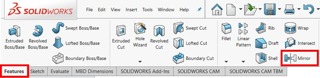
Figure 12.31 – The location of the Mirror command
- The mirror PropertyManager will be shown on the left. We can make the following selections:
- The Mirror Face/Plane, in this case, is the same as the default Right Plane. Hence, we can select Right Plane from the design tree, as shown in the following screenshot:
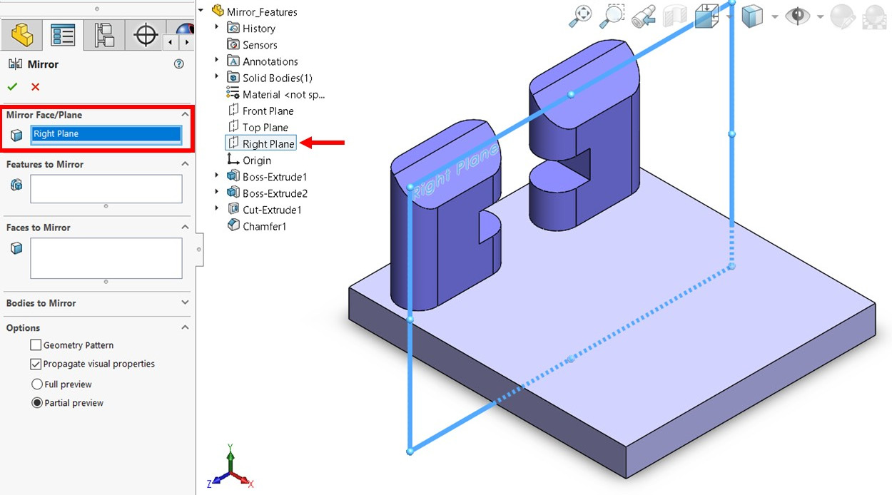
Figure 12.32 – A plane is used to reflect the features
Tip
You can preselect the mirror plane before clicking the Mirror command.
- For Features to Mirror, we want to mirror a total of three features, which are Boss-Extrude, Cut-Extrude, and Chamfer. We can select all of these features from the design tree, as shown in the following screenshot. Alternatively, we can select the features directly by selecting them from the 3D model shown in the canvas:

Figure 12.33 – We can select features to mirror from the design tree
- After confirming the preview, click on the green checkmark to apply the mirror. The final model will look as follows:

Figure 12.34 – The final 3D model after mirroring the specified features
In this exercise, Mirror Face/Plane happened to be the same as the default Right Plane. However, it can be any straight face or surface from the model itself. It can also be a new plane that we generate ourselves using reference geometries. We can also mirror any number of features in one go. Note that, similar to mirroring sketches, any modifications we apply to the original features will be reflected in the mirrored features. Before we conclude our discussion of the Mirror command, let's explain two notable options shown in Figure 12.33 – Geometry Pattern and Propagate visual properties:
- Geometry Pattern: Checking this option will mirror a geometrical replica of the original shape while disregarding any logical arrangements that were used, such as features end conditions, if any.
- Propagate visual properties: Checking this option will copy the visual textures and colors of the original shape to the mirrored shape.
Tip
Mirroring features is mostly more convenient than mirroring sketches. This is because, with features, we can mirror a combination of features that inherently include sketches. Hence, mirroring end features often results in less modeling time and less time when modifying the model afterward.
This concludes this section on mirroring features. We learned what the features mirroring function is, in addition to how to apply it. Next, we will cover another feature, known as the rib feature.
Understanding and applying the rib feature
Ribs are reinforcement structures that are used to help fix two sides together. In this section, we will learn what ribs are and how to create them using the SOLIDWORKS rib feature. We will also learn how SOLIDWORKS interprets the creation of ribs using the rib feature.
Understanding ribs
Ribs are often welded support structures that are added to link different components or parts together. It is common to find ribs within plastic objects such as toys. They are also commonly found in building structures. The following diagram shows two models, one Without Ribs and one With Ribs:
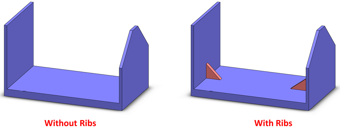
Figure 12.35 – 3D models with and without ribs
Note that we can create ribs out of other features, such as extruded boss and extruded cuts. However, the rib feature provides us with an easier method to both build and define a rib. Now that we know what ribs are and what the rib feature does, we will start learning how to apply it to a SOLIDWORKS model.
Applying the Rib command
In this section, we will learn how to use the Rib command to generate ribs in our models. We will create the model shown in the following diagram. The base model we will use can be downloaded from this book's GitHub repository. Note that the ribs are highlighted in detail views A and B, which we will generate in this exercise:
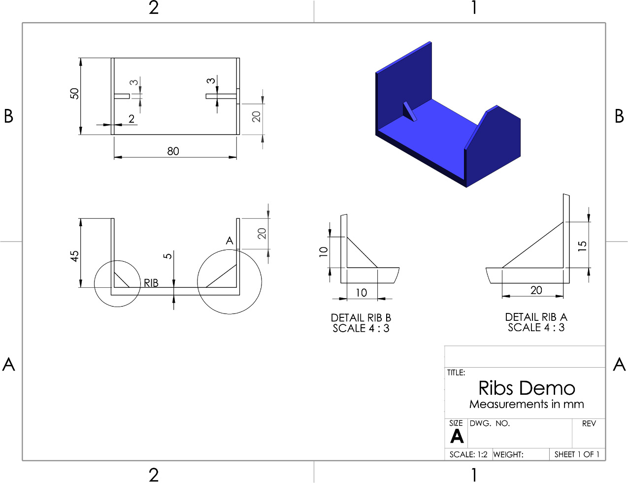
Figure 12.36 – The 3D model we will build in this exercise
To use the rib feature for this exercise, we can follow these steps:
- First, download and open the SOLIDWORKS part linked to this section concerning ribs. The model will look as follows. Alternatively, you can create the model from scratch using the information provided in the preceding diagram:

Figure 12.37 – You can download the following model with this section
- Select Front Plane from the design tree. The front plane is shown in Figure 12.35.
- In the Features tab, select the Rib command, as highlighted in the following screenshot:
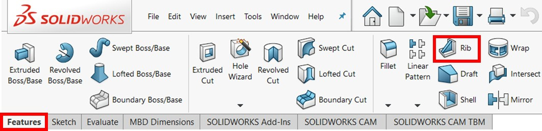
Figure 12.38 – The location of the Rib command
- Sketch a line that outlines the outer boundary of rib A, as follows. This sketch matches the DETAIL RIB A view on the drawing. Note that Steps 2 to 4 are interchangeable; we can choose the feature first, then select the plane and sketch. We can also sketch, then select the Feature command:

Figure 12.39 – The rib can be built with a single line sketch
- After we exit the sketch, we will notice the Rib command's PropertyManager window on the left. For rib A, the options and the preview can be set as shown in the following screenshot. These options will allow us to define our rib in terms of the following:
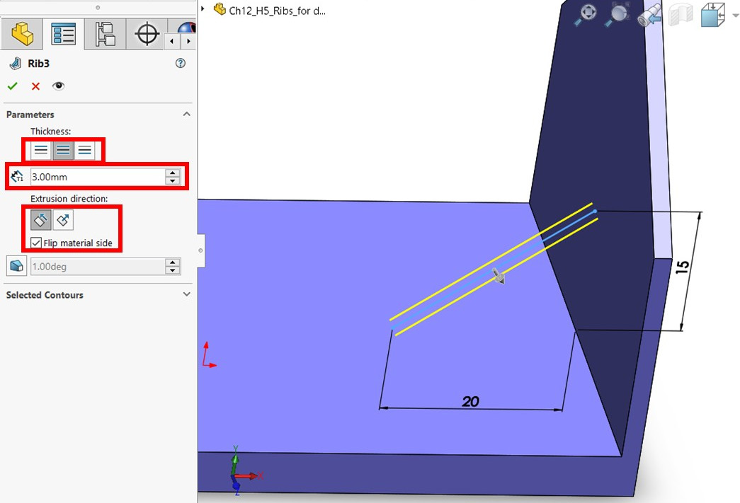
Figure 12.40 – The Rib command's PropertyManager window and its settings
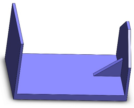
Figure 12.41 – The resulting rib after its application
- Follow Steps 2 to 6 again to create rib B. Make sure that you use the dimensions shown in the DETAIL RIB B diagram. The final model will look as follows:

Figure 12.42 – The final 3D model after applying both ribs
We likely have identical rib dimensions in products that we interact with within our day-to-day lives. However, we created ribs with different dimensions to practice how to use the tools.
Drafted rib
One of the key options we can utilize with ribs is adding a draft to them. This option can be used by enabling the Draft outward option shown in the feature's PropertyManager window, as highlighted in the following screenshot:

Figure 12.43 – The rib feature allows us to make a drafted rib
A drafted rib will have the same look as the drafts we covered in the Understanding and applying the draft feature.
This concludes how to use the Rib command. We covered what the rib feature is and how to apply it. All of the features we covered earlier in this chapter can be used to construct models directly. Next, we will cover multi-body parts, which is a method for creating parts rather than a feature.
Understanding and utilizing multi-body parts
In all of the applications we have explored in this book, each part file we made consisted of one body. We used assembly files to combine the different parts. In this section, we will explore a different approach with multi-body parts. We will cover what multi-body parts are, how they are created, and what the advantages of multi-body parts are.
Defining multi-body parts and their advantages
Multi-body parts are models made within a SOLIDWORKS part file that contain more than one separate body. Hence, they are called multi-body parts. The following diagram shows the contents of one SOLIDWORKS part file. However, the diagram on the left consists of one solid body, while the one on the right consists of two solid bodies. Note that the difference between these two diagrams is that the right-hand one has an extrusion cut that separates the large triangle (one solid body) into two triangles (two solid bodies):
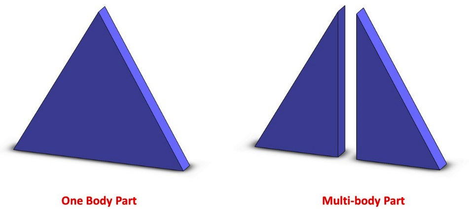
Figure 12.44 – A single body part and a multi-body part
However, we should not confuse multi-body parts with assemblies. The different bodies in multi-body parts are not dynamic, as is the case with the different parts in an assembly. This makes multi-body parts appropriate for certain applications that involve static interactions such as frames. This is due to the following advantages:
- The frame and other static elements will all be contained in one file, making them easier to access and modify.
- The work process is faster as we won't need to use more than one SOLIDWORKS file. Also, we won't need to create mates to ensure the different parts fit together, as is the case with assemblies.
However, assemblies also have other advantages over multi-body parts. These include the following:
- We can showcase the moving dynamics within a product.
- There's more flexibility in reusing parts in different assemblies. Also, we have more flexibility in exchanging an independent part.
- Creating separate drawings for each component is more convenient as the parts are set up in different files.
- Having parts in different files makes it easier to have separate part names and numbers for archiving or for inventory references.
There is no right or wrong answer to what approach to choose between assemblies and multi-body parts. As designers and practitioners, we will have to make the choice, weighing up the advantages of both approaches. To do that, we have to be familiar with both approaches. Next, we will create a multi-body frame to put what we just learned into practice.
Generating and dealing with a multi-body part
In this section, we will learn how to generate a part with multiple bodies. To demonstrate this, we will create the frame shown in the following diagram:

Figure 12.45 – The 3D model we will build in this exercise
Note that each element of the frame is indicated with a different number in the drawing, and the frame consists of four different bodies. To model this frame, we will follow these steps:
- Create body 1 as per the dimensions shown in the preceding diagram using the extruded boss feature. It should look as follows:
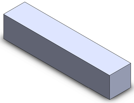
Figure 12.46 – A one-body part of body 1
- We will create the three additional bodies with one more extruded boss feature. To do this, we will follow steps similar to those that we have followed previously. However, before applying the extruded boss feature, we will uncheck the Merge result box, as highlighted in the following screenshot, which also highlights the sketch we used:

Figure 12.47 – Unchecking the Merge result option will build the extrusions as separate bodies
- Click on the green checkmark to apply the extrusion. After doing that, we will see two differences compared to our usual extrusion. They are as follows:
- We will notice a line separating the different frames, as indicated in the following diagram. These lines indicate a separation between the different bodies in our part:

Figure 12.48 – The lines indicating separate bodies
- In the design tree, we will notice a tab with the title Solid Bodies, as shown in the highlighted design tree diagram. If we expand this, we will see a list of all of the different bodies we have in our part; clicking on any of them will highlight the body in the canvas. From this list, we can selectively hide, delete, or change the display or assign materials to a specific body by right-clicking on the listing and choosing from the different options:

Figure 12.49 – The design tree will show different bodies
This concludes one of the common ways to generate a multi-body part. We can also intentionally create separate bodies in the canvas, which will automatically result in multi-body parts. Also, whenever we apply features such as an extruded cut, which would result in physically separating bodies, we will have a multi-body part.
Note
One important aspect to note is that SOLIDWORKS, by default, will tend to merge bodies as that is a more common practice. Hence, any feature we apply that physically connects separate bodies will merge them unless we specify otherwise by unchecking the Merge result option.
Two important and useful elements concerning multi-body parts are the feature scope and being able to save bodies in different SOLIDWORKS part files. We will cover these two aspects next and apply them to our model.
Feature scope applications
The feature scope refers to the extent to which a feature is applied. For example, in a multi-body part, we can apply a feature such as an extruded cut and specify which body can be included in the cut and which body should not be included. In our exercise, notice in the drawing provided that there is a hole that goes through bodies 2 and 4 and skips body 3.
To utilize the feature scope, we can follow the same steps that we followed for an extruded cut. However, we will notice that the options under the Feature Scope tile in our cut extrude PropertyManager. We can see some options highlighted in the following screenshot with both the sketch and the other options for the extruded cut feature. Under the Feature Scope options, we can select the Selected bodies option and uncheck Auto-select.
Then, we can manually select bodies 2 and 4, as highlighted in the following screenshot:

Figure 12.50 – Feature Scope allows us to select which body a feature will affect
As usual, click on the green checkmark to apply the extruded cut feature. Note that the resultant hole is only applied to only the selected bodies, as shown in the following diagram:

Figure 12.51 – The final multibody 3D model
Being able to scope features enables us to apply our design intent faster and more efficiently as it reduces the number of features we need to apply to reach the same result.
Separating different bodies into different parts
Now that we have the frames, we can face a situation in which we need to have each frame element or body in a separate SOLIDWORKS file. This could be needed for purposes such as generating separate drawings, inputting the separate files into a rapid prototyping machine, or other applications. SOLIDWORKS enables us to separate the different bodies into separate SOLIDWORKS part files. To do this, follow these steps:
- Go to Insert | Features | Save Bodies..., as highlighted in the following screenshot:

Figure 12.52 – Different bodies can be saved in different SOLIDWORKS part files
- This will prompt you to select which bodies you want to save separately. You can select the bodies directly from the canvas or the list by checking the box under the save icon. Once you approve the Save Bodies command, a new file will be generated for each body. By default, the new files will be located in the same folder as the original file. These command options are shown in the following screenshot:

Figure 12.53 – The Save Bodies command allows us to pick which specific bodies we want to save
After applying the Save Bodies command, we will notice that this command is listed in the design tree, as highlighted in the following screenshot. The separate files will only reflect the shape from before that feature's listing. Hence, applying more features after using the Save Bodies command will not update the already saved bodies. We can drag the features we want to be reflected above the Save Bodies command in the design tree:

Figure 12.54 – The Save Bodies command will appear in the design tree after its application
This concludes our coverage of multi-body parts. In this section, we learned about the following:
- What multi-body parts are
- The difference between multi-body parts and assemblies and the advantages of each
- How to create a multi-body part
- How to utilize the features scope function
- How to save different bodies into different SOLIDWORKS part files
Knowing how to utilize multi-body parts to our advantage will enable us to optimize the software when targeting different applications, such as static furniture design or beam structure design.
Understanding and applying linear, circular, and fill feature patterns
Feature patterns allow us to duplicate features quickly according to a certain pattern. In this section, we will learn about the linear, circular, and fill patterns. In addition, we will learn how to apply them using the available SOLIDWORKS tools.
Understanding feature patterns
Feature patterns allow us to duplicate features quickly according to a certain pattern. They are similar to sketching patterns, which we covered in Chapter 4, Special Sketching Commands. However, with feature patterns, we can build patterns of features and bodies rather than patterns of sketch entities. In this section, we will cover three types of patterns, as follows:
- Linear pattern: Duplicates features or bodies in a linear fashion.
- Circular pattern: Duplicates features or bodies in a circular fashion.
- Fill pattern: Duplicates features within a set boundary by following a specific pattern. Possible patterns include perforation, circular, square, and polygon.
The following table highlights the difference between the three types of patterns:
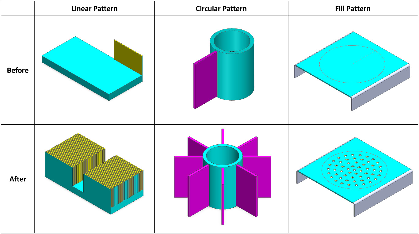
Figure 12.55 – The different types of patterns
Now that we know what to expect of each type of pattern, we can start applying them in the software. Let's get started with linear patterns.
Applying a linear pattern
In this section, we will learn how to use the Linear Pattern command to create pattern features. We will create the heat sink shown in the following diagram. The base model we will use can be downloaded from this chapter's GitHub repository. In the following diagram, note the repeated fins, which we will utilize linear patterns to generate:
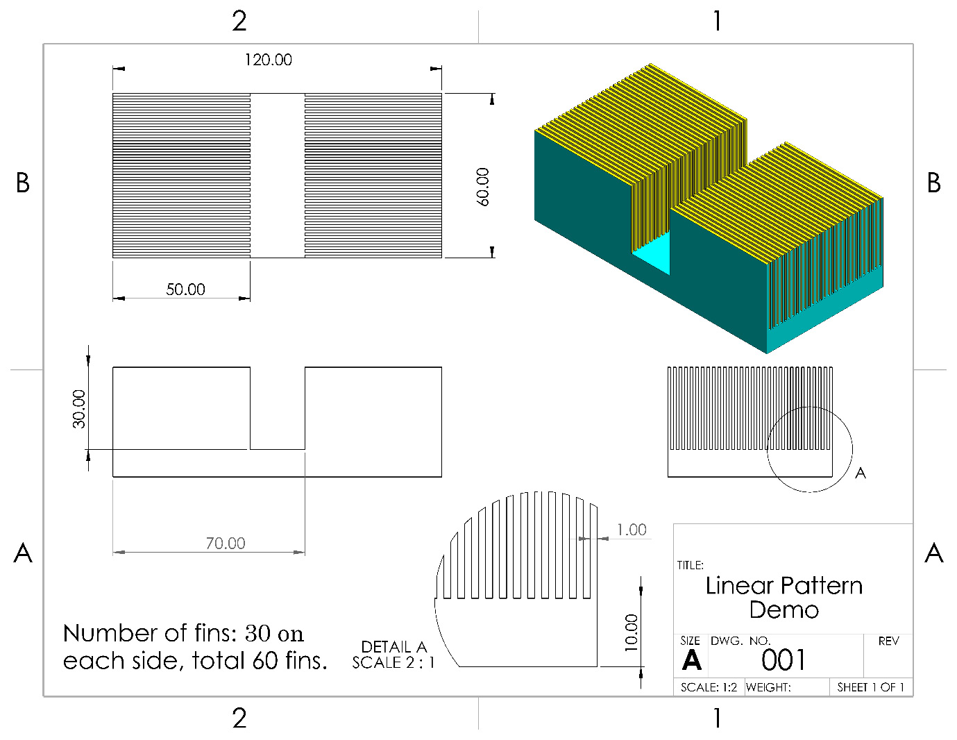
Figure 12.56 – The heat sink we will build in this exercise
To create the linear pattern, follow those steps:
- First, download and open the SOLIDWORKS part linked to this section concerning feature patterns. The model will look as follows. Alternatively, you can create the model from scratch by using the preceding diagram:

Figure 12.57 – The 3D model that's available for this exercise

Figure 12.58 – The location of the Linear Pattern command
- Check the Features and Faces box and select the fin, as shown in the following screenshot:

Figure 12.59 – The Features and Faces section of the linear pattern
Hint
You can use the canvas design tree to select features as well.
- For Direction 1, select the smaller side edge, as highlighted in the following screenshot. A preview will then show the projected pattern:

Figure 12.60 – The selection for Direction 1 using an edge
Hint
To indicate the direction of the pattern, we can also select lines from sketches, planes, planar surfaces, axes, and temporary axes.
- For the end condition, do the following:
- Select Up to reference, then select the end surface of the heat sink base for the first reference geometry, as shown in the following screenshot.
- Select the Selected reference option, then select the indicated face of the fin for the second seed reference, as shown in the following screenshot.
- Define the pattern by the number of instances and input 30 for that, as shown in the following screenshot:
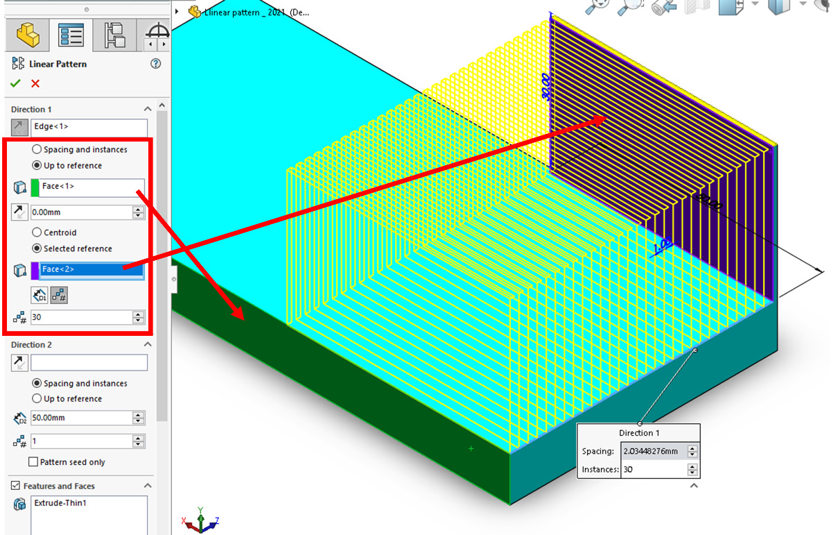
Figure 12.61 – Defining Direction 1 for the linear pattern
With that, we have defined one direction, as you will see from the preview on your screen. This whole pattern is repeated one more time for Direction 2. So, let's start defining the second direction in the same way.
- Repeat Steps 4 to 5 for Direction 2, as follows:
- Select the long edge of the base for the direction, as shown in the following screenshot.
- Select Up to reference, then select the end surface of the heat sink base for the first reference geometry, as shown in the following screenshot.
- Select the Selected reference option, then select the indicated face of the fin for the second seed reference, as shown in the following screenshot.
- Define the pattern by the number of instances and input 2 for that, as shown in the following screenshot:

Figure 12.62 – Defining Direction 2 for the linear pattern
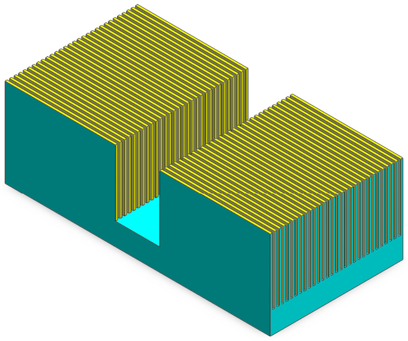
Figure 12.63 – The final 3D model after applying the linear pattern
With that, we have applied the linear pattern. Now, let's define two more important options we did not use in this exercise – Bodies and Instances to Skip. We can find these options in the linear pattern PropertyManager window, as shown in the following screenshot:
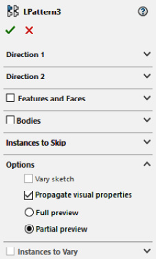
Figure 12.64 – The different options available for a linear pattern
Let's look at these options in more detail:
- Bodies: This allows to build a pattern of bodies instead of features. This option can be used when we're working with multi-body parts.
- Instances to Skip: This allows us to exclude some of the duplicates that are generated by the pattern manually. This works similarly to the sketch patterns we covered in Chapter 4, Special Sketching Commands.
With that, we can conclude our discussion on linear patterns. Next, we will take a closer look at circular patterns.
Applying a circular pattern
In this section, we will learn how to use the Circular Pattern command to pattern features. Note that setting up a circular pattern follows a similar procedure to setting up a linear pattern. We will create a simple waterwheel design, as shown in the following diagram. Note the repeated blades that we will use the circular pattern to generate:

Figure 12.65 – The water wheel we will create in this exercise
To complete the exercise, follow those steps:
- First, download and open the SOLIDWORKS part linked to this section regarding feature patterns. The model looks as follows. Alternatively, you can create the model from scratch using the preceding diagram:

Figure 12.66 – The 3D model for this exercise
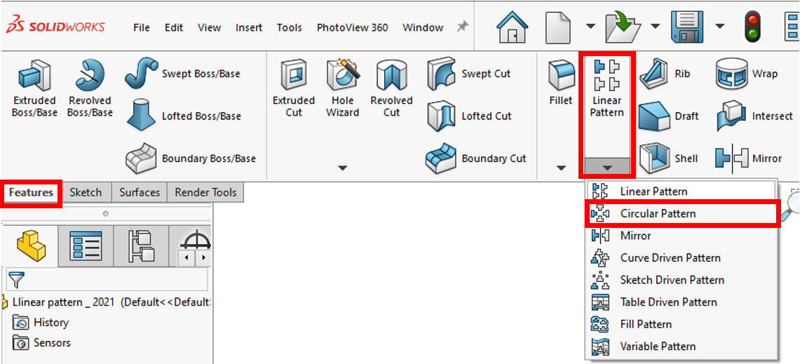
Figure 12.67 – The location of the Circular Pattern command
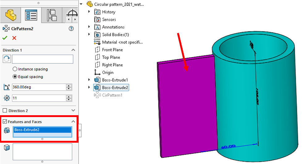
Figure 12.68 – Features section for the linear pattern
Hint
You can use the canvas design tree to select features as well.
- For Direction 1, select the circular face, as shown here. Also, set the pattern to equal spacing, the angle to 360, and the instances to 8. Note that the number of instances includes the base feature:

Figure 12.69 – The selection for Direction 1 using a circular face
Tip
For the direction, we can use faces, circular edges, axes, and temporary axes.

Figure 12.70 – The final 3D model after applying the linear pattern
With that, we can conclude our application of the circular pattern. Other options, such as Bodies and Instances to Skip, have the same functionality as their counterparts for linear patterns. Next, we will discuss the fill pattern feature.
Applying a fill pattern
In this section, we will learn how to use the Fill Pattern command to pattern features. We will create the simple holes grill shown in the following diagram. Note the repeated square holes on the top surface; we will use these to the fill pattern feature to generate. Fill patterns are commonly used for grills that are used in sound systems, in ventilation for electronics, and for weight reduction purposes:

Figure 12.71 – The 3D model we will create in this exercise
Before applying the fill pattern, we must know that a fill pattern requires a boundary and a direction to be applied. Thus, we will be defining them before applying the pattern.
To complete this exercise, follow those steps:
- First, download and open the SOLIDWORKS part linked to this section regarding feature patterns. The model looks as follows. Alternatively, you can create the model from scratch by using the preceding diagram:

Figure 12.72 – The base model for this exercise
- Sketch the 80 mm circular boundary on the top surface using a solid line. Then, sketch a construction line for the direction, as shown in the following screenshot:

Figure 12.73 – The fill pattern requires a boundary and direction to apply
Tip
The boundary and direction do not have to be sketched separately. The existing linear surface can be used as a boundary, and existing edges can be used for direction. However, making new sketches allows us to build custom boundaries.
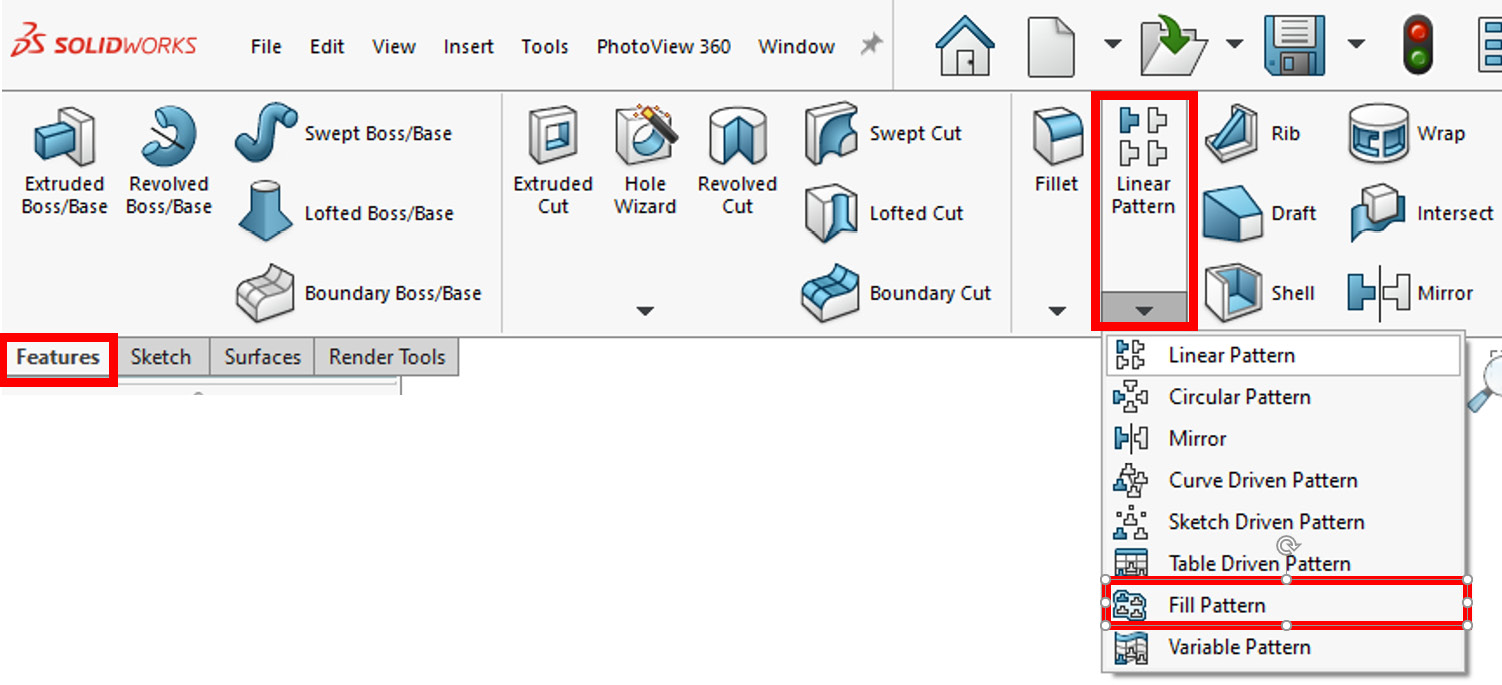
Figure 12.74 – The location of the Fill Pattern command

Figure 12.75 – A fill boundary is required for the fill pattern
- For Pattern Layout, select the Circular pattern and select the construction line for the direction, as shown in the following screenshot:

Figure 12.76 – Selecting the layout and direction
- Check the Features and Faces box, select Create seed cut, and pick the square option. We can specify 3 mm as the side length. The Vertex selection indicates the origin point of the pattern. For example, for a circular pattern layout, the vertex will indicate the center of the square. These settings are highlighted in the following screenshot:

Figure 12.77 – The settings for the feature cut
Note
The Create seed cut option allows us to create common cuts that are associated with fill patterns. However, we can create fill patterns for any other feature as well.
- Now, we can fine-tune the pattern. Make sure that the Target spacing option is selected. Then, set Loop Spacing to 8 mm, Instance Spacing to 10 mm, and Margins to 3 mm. Note that the on-screen preview will change as we are adjusting those parameters. Also, note that Instance Count will change according to the number of repeated instances. The following screenshot highlights these settings:

Figure 12.78 – The pattern layout instance's settings
Tip
It is common to keep adjusting the instance settings in a trial-and-error fashion until we get the desired result.
- Click on the green checkmark to apply the fill pattern. The resulting 3D model will look as follows:

Figure 12.79 – The final 3D model after applying the fill pattern
With that, we have implemented the fill pattern feature. In this exercise, we applied the fill pattern within one boundary. However, it is also possible to apply a fill pattern that covers more than one boundary at a time. We'll look at this in the next section.
Applying the fill pattern to more than one boundary
In the previous exercise, we applied a simple fill pattern to one boundary area. However, the feature can apply one pattern that extends more than one boundary. This allows us to create harmonious-looking patterns with an elegant look and feel. To highlight this, let's look at the following pattern:

Figure 12.80 – Mutiboundary circular fill pattern with a central vertex
This fill pattern follows a circular pattern originating from the rectangular piece's center, as indicated by the Vertex. Here, we can see the formation of the circular fill pattern with the selected vertex as its center.
Note
The different boundaries can be in one sketch, or they can be in more than one sketch.
The vertex can also be located outside the areas of the boundaries as we see fit for our design. For example, the following circular fill boundary has the same specifications as the preceding one, with the vertex located differently. Here, the overall circular alignment of the pattern is preserved. However, the center of the base circle is located differently:

Figure 12.81 – Mutiboundary circular fill pattern with a corner vertex
With that, we have finished looking at the major types of feature patterns. We covered the linear, circular, and fill patterns. The linear and circular feature patterns are very similar to the patterns available for sketching, while the fill pattern allows us to apply patterns within selected boundaries easily. All these feature boundaries allow us to build patterns for specific features or whole bodies.
Summary
In this chapter, we learned about a variety of relatively advanced features for building more complex models. We covered the draft, shell, and rib features for creating specific geometries faster. We also learned about using the Hole Wizard to create industry-standard holes and covered how to mirror features to save us time that would otherwise be spent remaking features. We also learned about multi-body parts, their advantages, and how to utilize them. At the end of this chapter, we learned how to apply linear, circular, and fill patterns for features and bodies, which allow us to duplicate features or bodies in specific formations.
Knowing about the topics that were covered in this chapter is what separates professional users of SOLIDWORKS from amateurs. Mastering this chapter's topics will help you save time and create complex shapes faster while capturing more specific design intents.
In the next chapter, we will cover equations, configurations, and design tables. These skills will allow us to create more connected models and allow us to have multiple variations of a part within one part file.
Questions
Answer the following questions to test your knowledge of this chapter:
Note
The following questions will reinforce the main topics we learned in this chapter. However, it is also good practice to pick random objects and model them in SOLIDWORKS to improve your skills.
- Describe the functions of the draft, shell, and rib features.
- What is the Hole Wizard, and why is it useful?
- Create the following part in SOLIDWORKS. Hint: Use the draft and shell features:
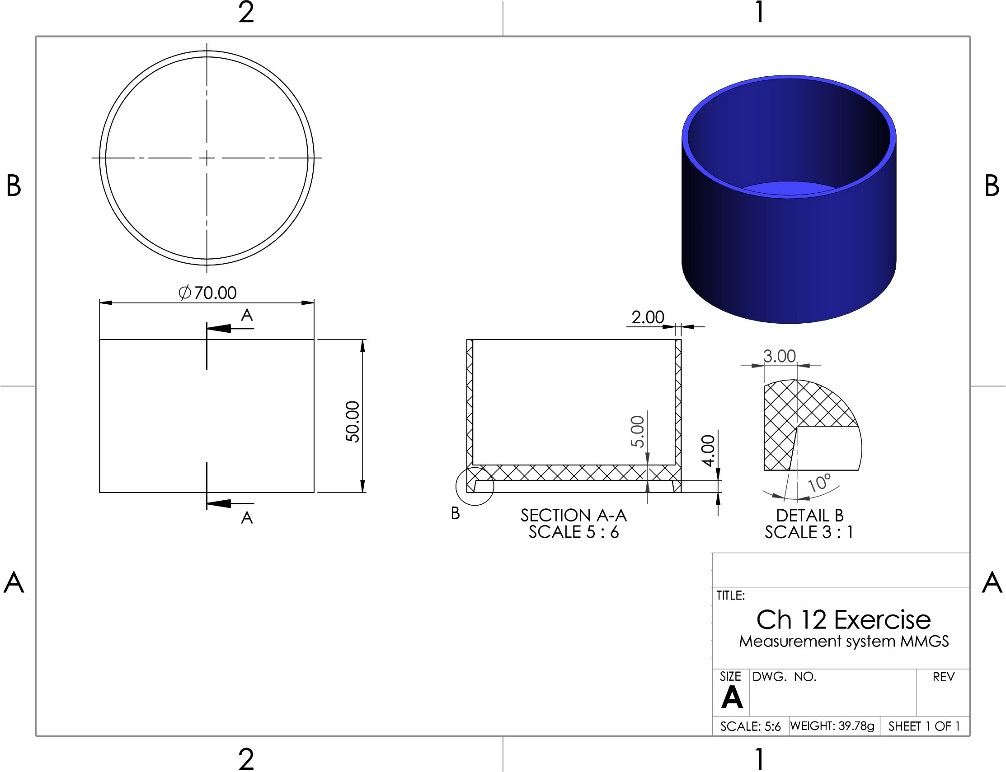
Figure 12.82 – The drawing for Question 3
- Create the following part in SOLIDWORKS. Hint: Use the rib feature and the Hole Wizard:
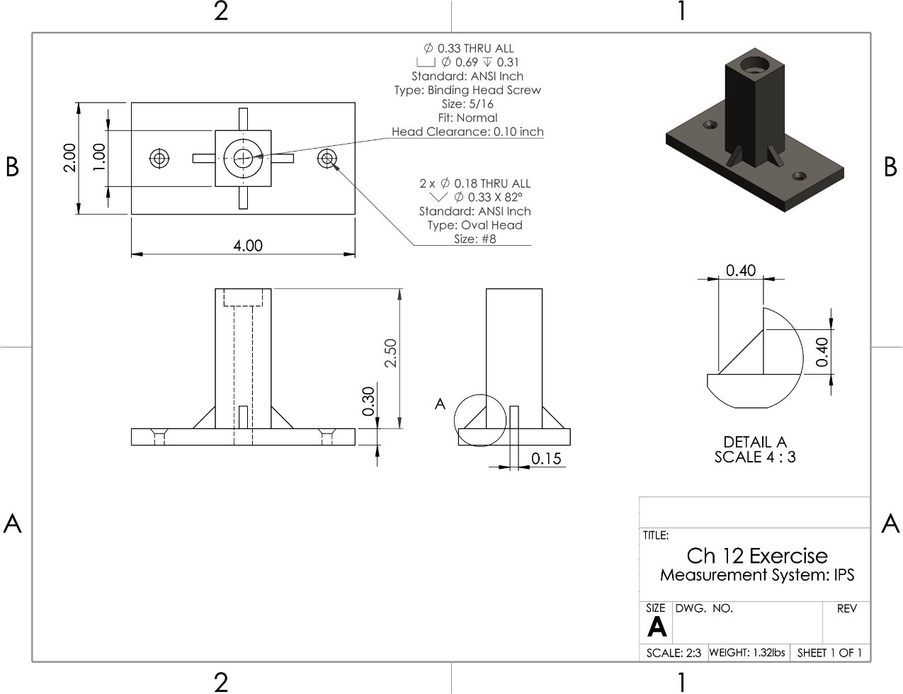
Figure 12.83 – The drawing for Question 4
- Create the following part in SOLIDWORKS. Hint: Use the rib and draft features and the Hole Wizard. You may also use reference geometries and the swept boss. Due to the amount of information that this part contains, the drawing has been split into two diagrams. Both diagrams are for this one question:
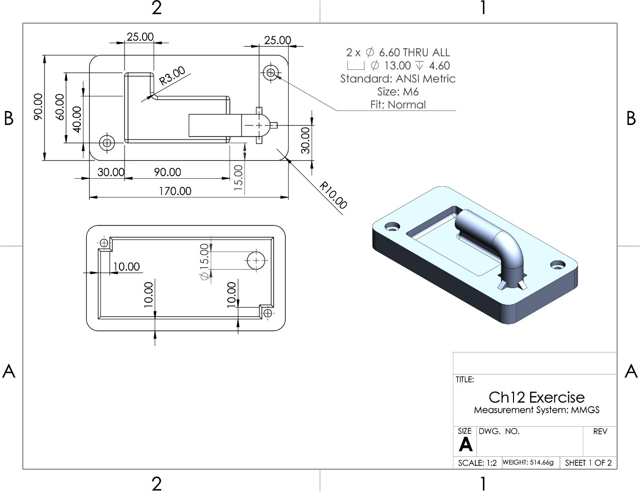
Figure 12.84 – The first drawing for Question 5

Figure 12.85 – The second drawing for Question 5
- What are multi-body parts, and what are some advantages of using them?
- Create the following frame in a multi-body format. Use the annotations in the drawing for the different bodies. Hint: Use features scope to extrude cut the slot shown on bodies 2 and 4:
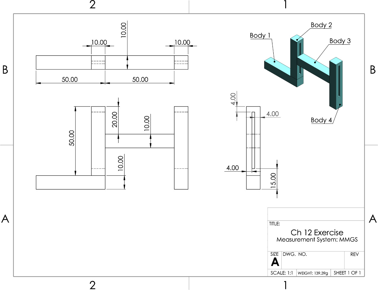
Figure 12.86 – The drawing for Question 7
Important Note
The answers to the preceding questions can be found at the end of this book.