
Chapter 11: Bill of Materials
Most assemblies usually consist of multiple parts. For example, a simple coffee table would have four legs, a top, and perhaps some screws. Other more complex assemblies, such as engines, would contain hundreds of different parts. A Bill of Materials (BOM) can help us list and communicate those different assembly parts. Apart from the list of parts, it also helps communicate any other desired information, such as cost, materials, and part numbers. This chapter will enable us to create standard BOMs. It will also enable us to modify and utilize equations in our BOMs.
The following topics will be covered in this chapter:
- Understanding BOMs
- Generating a standard BOM
- Adjusting information in the BOMs
- Utilizing equations with BOMs
- Utilizing parts callouts
By the end of the chapter, we will be able to generate a standard communicative BOM that goes with our drawings. We will also be able to fine-tune the information displayed to fully match our needs.
Technical requirements
This chapter will require access to SOLIDWORKS software.
The project files for this chapter can be found in the following GitHub repository: https://github.com/PacktPublishing/Learn-SOLIDWORKS-Second-Edition/tree/main/Chapter11.
Check out the following video to see the code in action: https://bit.ly/3s6sZXy
Understanding BOMs
A BOM is an essential part of any engineering drawing representing an assembly. This is because it shows relevant information about the different parts that are present in our final product. Before we make BOMs, we need to understand what they are and their purpose. In this section, we will learn about BOMs and introduce the BOMs we will create in this chapter. Let's start.
Understanding a BOM
BOMs are often part of engineering drawings, specifically with drawing sheets of assemblies. They show more specific information about the product we are working on. For example, a typical list of materials might contain the following information:
- Names of the parts in the assembly
- Part numbers
- Quantity of each part
- Sequential listing of each entry
However, they are not limited to this information. BOMs are customizable, depending on the established practices and the application needs. Other information that can often be found in BOMs is cost, manufacturer, materials, store locations, reference numbers, and so on. The following are two examples of assembly drawings with BOMs. Note that each table is considered a BOM. The drawing shown in Figure 11.1 is for a mechanical cap. The BOM there includes PART NAME, PartNo, DESCRIPTION, QTY., Cost per part, and Total Cost per part. It also highlights the Total Cost sum for all the parts and the Highest Cost value for one part, and also includes a subassembly and its parts, noted under Damper Assembly:
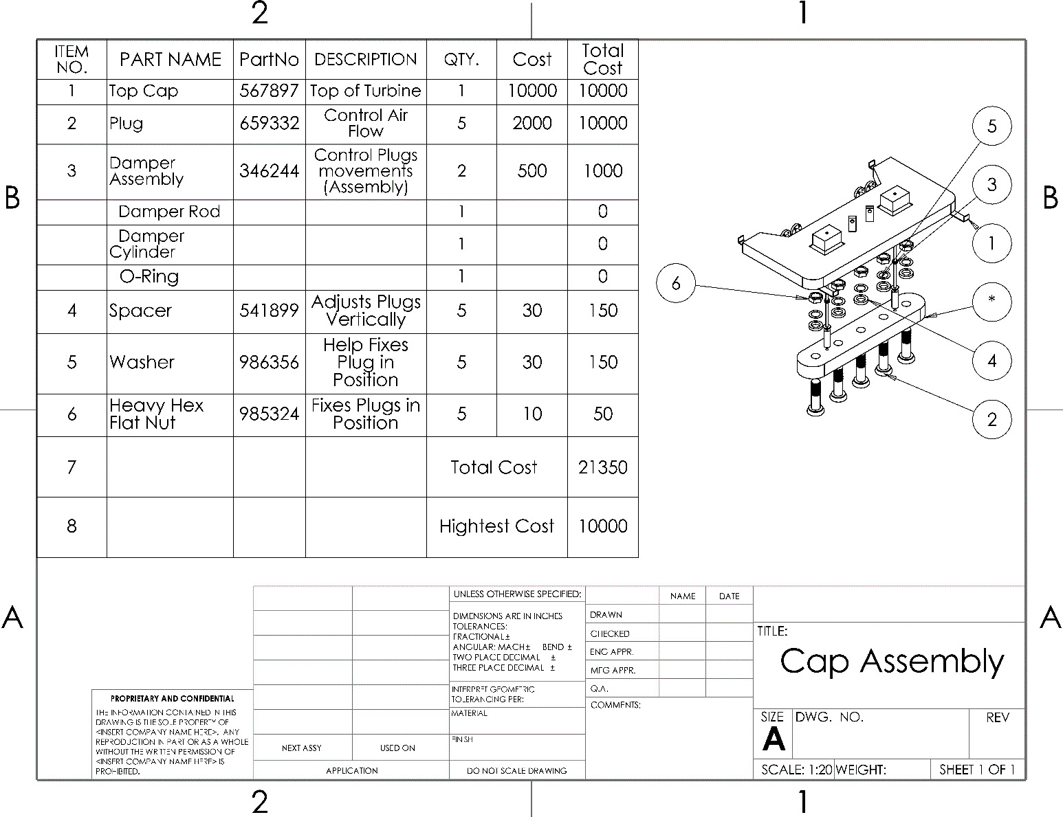
Figure 11.1 – A drawing with a BOM of a cap assembly
The following diagram and BOM are of a simple coffee table. The bill includes PART NAME, COST PER PART (USD), QTY., and TOTAL COST PER PART (USD). Note that the information in this bill is different than the one shown previously:

Figure 11.2 – An assembly drawing with a BOM for a coffee table
Throughout this chapter, we will be working to create the preceding drawing sheet and BOM from scratch. You can download all of the parts and assembly files for this chapter. Our first step will be to generate a standard BOM, which we will do next.
Generating a standard BOM
In this section, we will learn how to generate a standard BOM using the tools provided by SOLIDWORKS drawings. We will start by inserting views of our model into the drawing and then generate a BOM. A standard BOM is our starting point when generating those bills within SOLIDWORKS drawing tools. After generating the standard bill, we will be able to modify it further so that it matches our specifications.
Inserting an assembly into a drawing sheet
A BOM often accompanies assemblies. This is because the BOMs will indicate the parts that exist in the assembly. Hence, we will start by adding a drawing of the assembly to our sheet. Inserting an assembly works the same way as inserting a part. We can use the following steps:
- Open a new drawing file and pick the A (ANSI) landscape sheet format.
- Go to View Palette, browse for the assembly file we downloaded with this chapter, and select it:
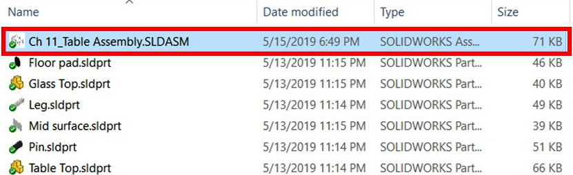
Figure 11.3 – Inserting the assembly file into the drawing
- In View Palette, select the two views, that is, the *Isometric view and Bottom View, and insert them into the sheet, as shown in the following screenshot:

Figure 11.4 – Inserting the Isometric and Bottom View into the drawing
- Change the scale to 1:15 and the display to Shaded With Edges for both views. Our drawing sheet should look as follows:

Figure 11.5 – The drawing sheet with the coffee table assembly
This concludes this section on adding an assembly to a drawing sheet. Note that it follows the same rules as inserting parts. Next, we will generate our standard BOMs for this assembly.
Creating a standard BOM
Now that we have inserted the assembly file into the drawing sheet, we can generate a standard BOM for the assembly. To generate that, we can follow these steps:
- From the Annotation tab, select the Tables drop-down menu and select Bill of Materials, as shown in the following screenshot:
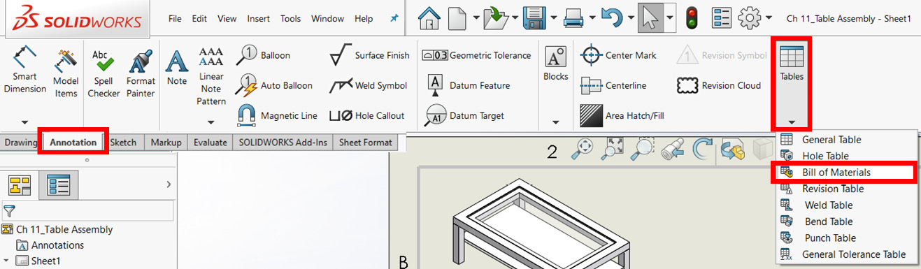
Figure 11.6 – The command to insert a BOM
Important Note
You can also insert a BOM by right-clicking on a drawing view, and then going to Tables and selecting Bill of Materials.
- Then, select the view for the model that you want to create the BOM for. Since both the drawing views are the same, we can click on either of them.
- This will show the Bill of Materials PropertyManager toward the left of the screen. As we are creating a standard default bill, we can simply leave all of the default options as they are, as highlighted in the following screenshot. Click on the green check mark to confirm the table:
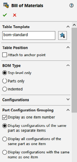
Figure 11.7 – Initial options for inserting a BOM
- After that, a standard BOM will be generated and displayed in our drawing sheet. We can place the bill on the sheet to get the drawing sheet shown in the following figure. We can adjust the table location by dragging it:

Figure 11.8 – The initial BOM after being inserted
This concludes how to generate a standard BOM. This will be our usual first step whenever we generate a BOM. Next, we will be working on adjusting the information in our bill to match the bill that was shown earlier in this chapter.
Adjusting information in the BOMs
Often, the information in the standard BOM doesn't exactly match our requirements. Hence, we need to be able to adjust the information shown to match our needs and requirements. In this section, we will learn how to adjust the table by changing information and adding information. By the end of this section, our drawing will look as follows. Note that the headings and information are different from how they were previously:
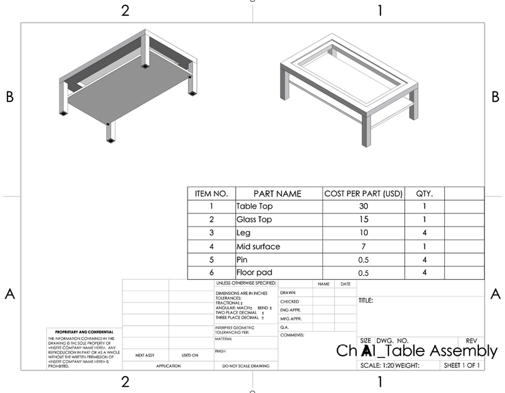
Figure 11.9 – The drawing by the end of this section
We will start by adjusting our bill's titles and information category.
Adjusting listed information in the BOM
Here, we will learn how to change information that is already listed in the table by making the following adjustments:
Changing a title in the BOM
Here, we will change the title of PART NUMBER to PART NAME, as highlighted in the following figure:

Figure 11.10 – Double-clicking on the cell title allows us to edit it
To do that, we can follow these steps:
- Double-click on the title cell. This will open up the title for editing.
- Change the title from PART NUMBER to PART NAME.
- Click anywhere outside the table to confirm the adjusted information.
When it comes to editing information, we can think of the table in a similar way to tables in Microsoft Excel.
Changing a column category
When generating a BOM, usually, each column is linked to a series of information that is gathered from the model itself; for example, column quantity (QTY.) automatically links to the number of parts that are present in the assembly. This will then display the quantity without us manually inputting it. We can still add more columns that are not linked with more manual information if needed. We can also adjust the information category for a specific column. In this section, we will change the DESCRIPTION column to COST PER PART (USD), as highlighted in the following figure. This new column will automatically be filled with linked cost information:
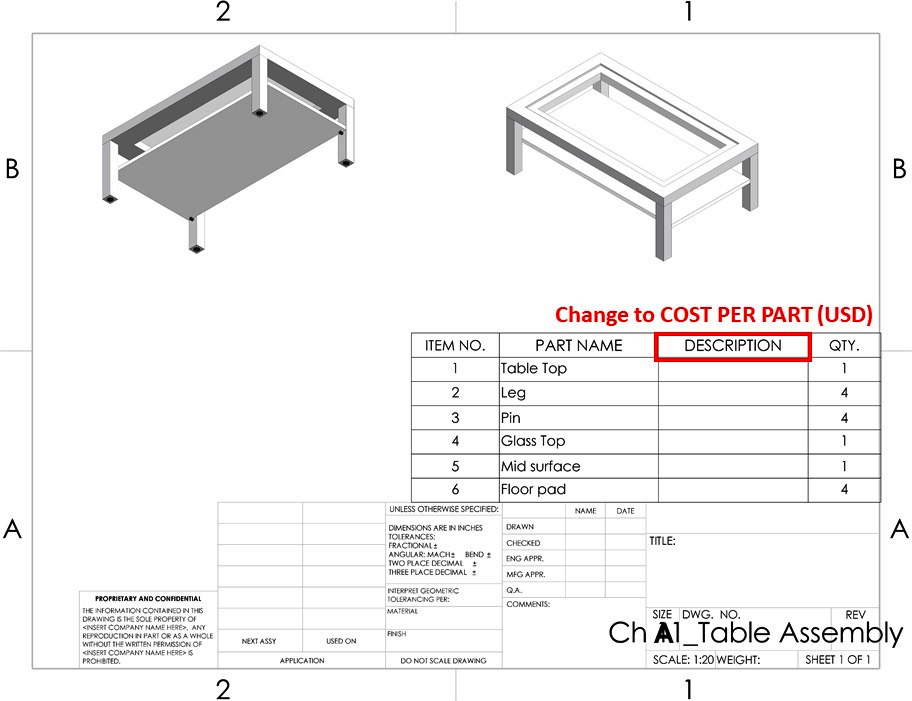
Figure 11.11 – We will adjust the DESCRIPTION column to COST PER PART (USD)
To adjust the column from DESCRIPTION to COST PER PART (USD), we can follow the following steps:
- Hover the mouse cursor over the table, and then select the letter C at the top of DESCRIPTION to select the whole column. Then, click on the column property, as highlighted in the following screenshot:

Figure 11.12 – The column property allows us to link the table to different information
- From the shown options, make the following selections:
- Column type | CUSTOM PROPERTY
- Property name | COST PER PART (USD)
This is highlighted in the following screenshot:

Figure 11.13 – The COST PER PART (USD) as found under the custom property
- Once we select that, the whole column will change, as well as all of the values in it. It will be filled with assigned values for the costs of each part. The BOM will look as follows:
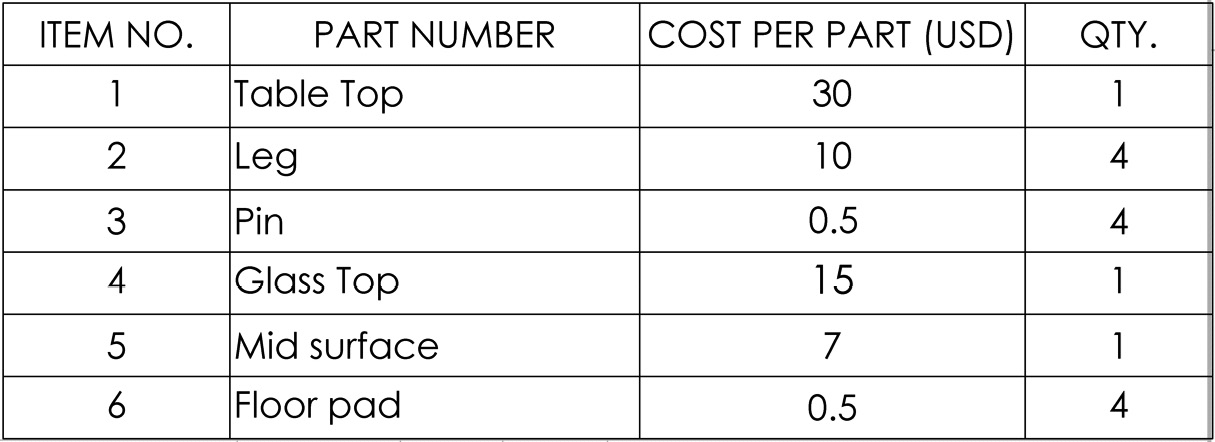
Figure 11.14 – Values are automatically filled for COST PER PART (USD)
Important Note
The values for the cost per part are not automatically generated by SOLIDWORKS. Rather, they are inputted manually into each part during the design process. The custom property function can then auto-call those values in the BOM.
This concludes how to adjust the column category for a specific column in our BOMs. Being able to adjust categories is a necessary skill that will allow us to extract information linked to our models and put it into our BOMs. Next, we will start changing the order of listed information in our bill by sorting it.
Sorting information in our BOMs
We can also re-sort the information in our BOMs to put it in a specific order. In our case, we will order the information based on COST PER PART (USD) in descending order. To do this, we can follow these steps:
- Right-click anywhere in the table and select Sort:
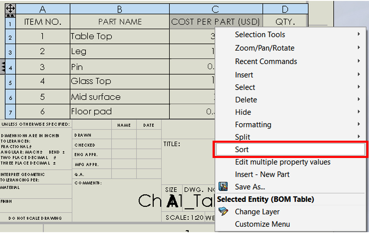
Figure 11.15 – The location of the Sort command
- We will get the following window. We can adjust the first Sort by option to COST PER PART (USD), and then select the Descending option next to it. Method should be selected as Numeric. Click OK after that:
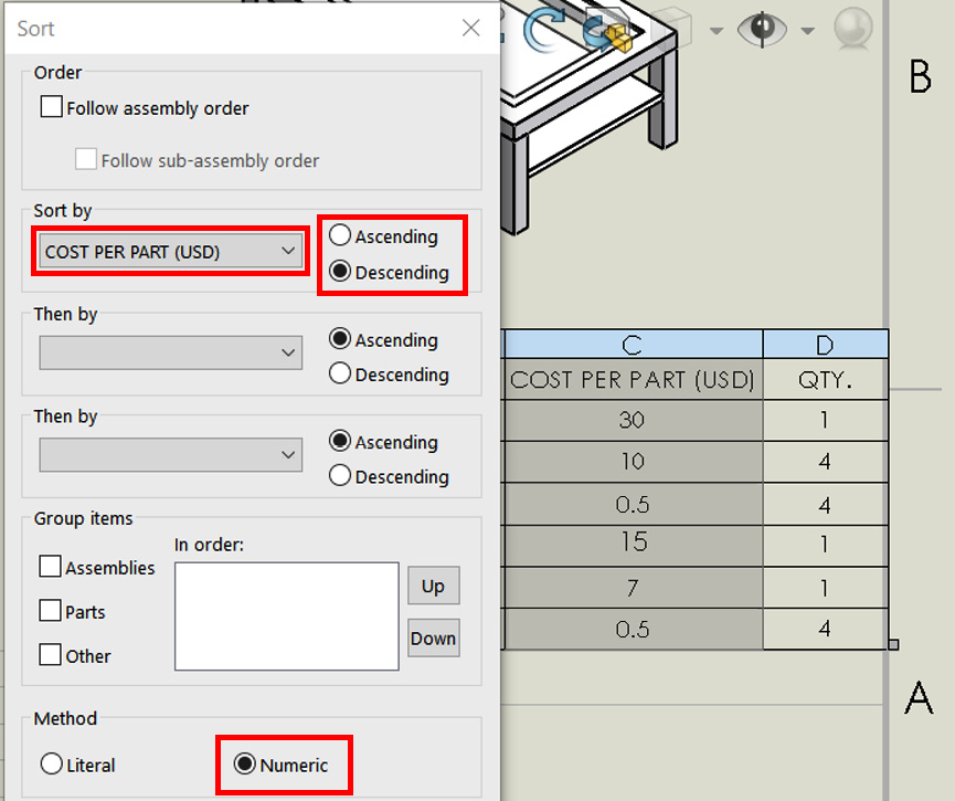
Figure 11.16 – The adapted setting for the Sort function
This will automatically re-sort the order of the whole table so that it's in descending order based on COST PER PART (USD). Finally, our BOM will be as follows:

Figure 11.17 – The Sort function allows you to order the BOM from most to least expensive
This concludes how to sort BOMs according to a specific order. We will often end up sorting our bills for a variety of reasons that will make it easier for us to find information. For example, we would want to sort a bill by cost per part to make it easier to identify the most and least costly parts. In an alternative scenario, we might sort the part names by alphabetical order to make finding a part easier by name. Next, we will learn how to add new columns to our table to accommodate new information.
Adding new columns
In this section, we will add a new column to our BOMs. The new row will be used to display the total cost for materials. The new column will be located after the QTY. column. To add a new column, we can follow these steps:
- Right-click anywhere in the QTY. column or in any cell in that column.
- Select Insert and then Column Right, as highlighted in the following screenshot:

Figure 11.18 – Inserting a new column
This will insert a new empty column to the far right so that we get the following table:

Figure 11.19 – We can insert new columns into our BOM for more information
This concludes how to add a new column to our BOMs table. Note that to add a new row, we can follow the same procedure for adding a column. When we insert a new BOM, the number of columns and rows is limited. Hence, it will be important for us to add rows and columns to include more information. In the next section, we will fill out the new column we added using equation functions.
Utilizing equations with BOMs
Equations in SOLIDWORKS drawings allow us to create simple calculations within our BOMs. This will allow us to perform operations such as addition, subtraction, division, and multiplication. In this section, we will learn more about what can we do with drawing equations. We will also use this feature for additional calculations in our BOMs.
What are equations in SOLIDWORKS drawings?
Equations allow us to perform several mathematical equations in our BOMs without leaving the SOLIDWORKS drawing interface. With equations, we can think of our BOMs as simple Excel sheets. With the equations function, we can perform two types of operations, functions and mathematical operations. Here, we will learn what these include.
Functions
Functions are limited programmed calculations that we can directly use to find specific information and display it in our bill of materials. They include the following:
- If: This opens an if statement that will allow us to apply a condition.
- Average: This finds the average between different values.
- Count: This counts the number of cells, regardless of whether the cell is empty or filled.
- Max: This finds the maximum value within the selected cells.
- Min: This finds the minimum value within the selected cells.
- Sum: This finds the sum of values with the selected cells.
- Total: This totals all of the values in the column that are located above the selected cell.
Next, we will learn about mathematical operations.
Mathematical operations
In addition to functions, we can also utilize different mathematical operations that are found in a basic calculator. These include the four main operations: addition, subtraction, multiplication, and division. We can use these operations by inputting them using the +, -, *, and / signs from the keyboard.
Now that we know about functions and mathematical operations, we will start using them in our bill.
Inputting equations in a table
Here, we will demonstrate how to add equations in a BOM. We will do this by revisiting our previous BOM. We will add TOTAL COST PER PART (USD) and TOTAL COST for a full product (a coffee table, in this case). To do this, we will start by applying the mathematical operation known as multiplication. Then, we will apply the total function.
Applying a mathematical operation
For this, we will fill the last column of our table with TOTAL COST PER PART (USD), as indicated in the following table. This will show the total cost of purchasing the quantity needed for each part. To calculate the value, we can multiply COST PER PART (USD) by QTY.:

Figure 11.20 – We will fill the new column with calculated values for the cost
To do this, we can follow these steps:
- Highlight the empty column at the far right by clicking the letter E at the top. Then, click on the Equation (Σ) command, as highlighted in the following screenshot:
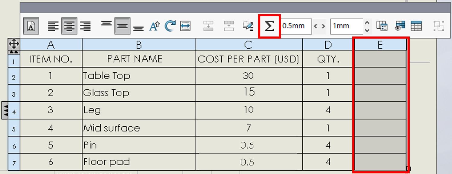
Figure 11.21 – The Equation command allows us to input mathematical operations in the BOM
- This will open the equation function, as shown in the following screenshot. In the equation space, we need to input the following – COST PER PART (USD)*QTY. Instead of typing all of this in the equation space, we can use the Columns drop-down menu. From there, we can select COST PER PART (USD). Then, we will notice that the column name was input in the equation space. After that, we can type * and select QTY. from the Columns drop-down menu:

Figure 11.22 – We can input equations to calculate values in the BOM
- Click on the green check mark to apply the equation. We will notice that the column was filled with numbers that are equal to the number under COST PER PART (USD), multiplied by QTY.. To make the table fuller, we can add a title to the column. The title can be TOTAL COST PER PART (USD). The final table will look as follows:
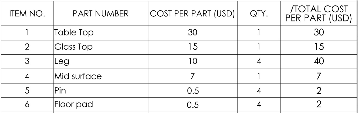
Figure 11.23 – The TOTAL COST column is auto-calculated using a simple multiplication
This concludes using multiplication. All the other operations, such as addition and subtraction, can be applied in the same way. Next, we will learn how to apply a function.
Applying an equation function
Here, we will apply the Total function in our BOM. Using this function, we will add all of the values under TOTAL COST PER PART (USD), which we just created. This will give us the total cost per coffee table. To do this, we can follow these steps:
- Add a new empty row at the bottom of the table. We can do that by right-clicking any cell at the bottom and inserting a row.
- Select the cell bottom cell under the TOTAL COST PER PART (USD) column and select Equation (Σ).
- In the equations panel, select TOTAL under the Functions drop-down menu, as highlighted in the following screenshot. Once we select that, the word TOTAL will appear in the equation space:

Figure 11.24 – The TOTAL function adds all the values on top of it
- Click on the green check mark. Then, the value of the last cell (E8) will change to 96, which is the sum of all of the numbers in that column. To make the table clearer, we can add the word TOTAL in cell D8. The resulting BOM will be as follows. Note that when editing cell D8, SOLIDWORKS will ask us whether we want to break the link in the cell and continue editing it; click Yes to edit:
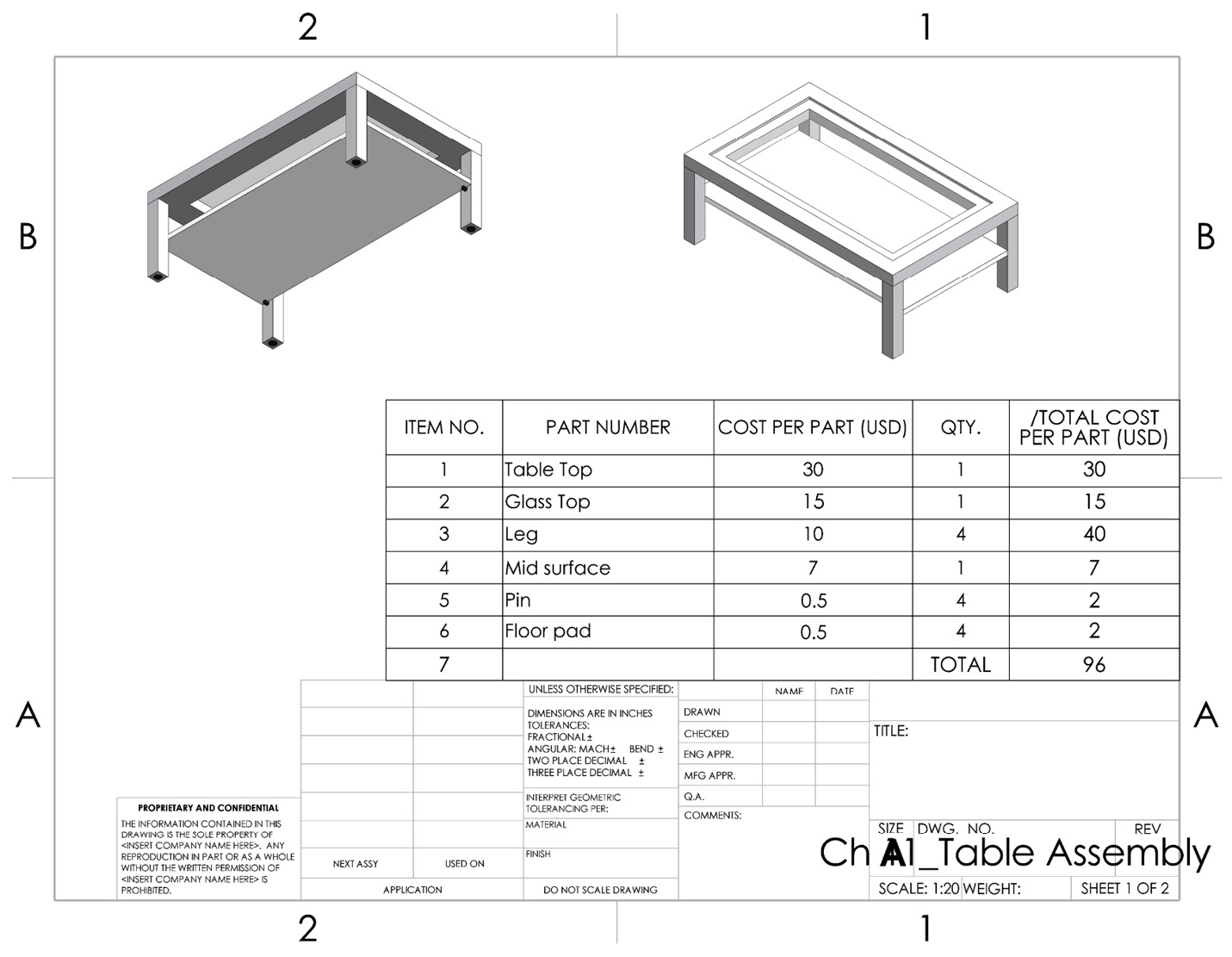
Figure 11.25 – Our new BOM after calculating the total cost
- It is good practice to try cleaning our bill as much as possible. For example, in the preceding bill, we can remove item number 7, as that row only has the total and does not include an item. To hide that item number, we can right-click on that cell and select Hide Item Number, as highlighted in the following screenshot:

Figure 11.26 – Hiding the last item number can get us a cleaner BOM
This concludes our work with equations within BOMs. Using equations will allow us to generate new numerical information in our table that is not linked to a particular part. A common application of equations is in relation to the costs of parts. Next, we will learn how to add callouts to the assembly for easier referencing between our bill and the visual display of the assembly.
Utilizing parts callouts
In this section, we will cover how to add callouts to the parts in our BOM. These can help us identify the location of the items in the drawing itself. Here, we will cover auto balloon callouts. To create these callouts, we can do the following:
- From the Annotation tab, select the Auto Balloon command, as highlighted in the following screenshot:

Figure 11.27 – The location of the Auto Balloon command
- Click on the two views we have on the drawing, one after another. You will notice balloons popping up with numbers and arrows pointing toward different parts, as shown in the following screenshot. Note that each number in a balloon matches the number in the BOM:

Figure 11.28 – Balloons indicate the item numbers matching the BOM
- In the PropertyManager, we have multiple options to adjust the callout. For this exercise, adjust the options highlighted in the following screenshot. After adjusting these settings, click on the green check mark to apply the balloon callouts:

Figure 11.29 – The Auto Balloon command PropertyManager
The final result of our drawing would look as follows. Note that we can manually drag the balloons to change their position as we see fit:

Figure 11.30 – The final drawing with a clean and communicative BOM
Other than the item numbers displayed in Figure 11.30, we can adjust the type of information we want to display. We can see those options in the Auto Balloon PropertyManager, as indicated in the following figure:

Figure 11.31 – The balloons can display different information other than the item number
This concludes how to create auto balloons for display purposes in our drawing. Note that these balloons will enable anyone who views the drawing to link the information in the BOMs to the displayed assembly.
Manual Balloon command
The Auto Balloon command enables us to quickly display related information to more than one part. However, if we want to include a few balloons with specific information, such as written text notes or any other custom property, then manually adding a balloon can be a more efficient option. Let's examine this by adding a box-shaped balloon linking to the tabletop with the Cut First text. To do this, follow these step:
- Select the Balloon command, as shown in the following figure:

Figure 11.32 – The location of the Balloon command
- Under Settings in the PropertyManager, select the Box and Tight Fit options, as shown in the following figure:

Figure 11.33 – We can set up the shape and text of the balloon per our needs
- Under Balloon text:, select the Text option and type Cut First, as shown in Figure 11.33.
- Using the cursor, go back to the drawing canvas and attach the box-shaped balloon to the tabletop. We will end up with the following figure:

Figure 11.34 – The resulting drawing with a box-shaped balloon
Other than the custom text we did in the previous example, the balloon can also link to the parts' properties and extract information from there in the same way that custom properties work in the BOM. At this point, we can conclude our discussion on utilizing the ballooning options to display specific communicative information.
Summary
Most of the products we work with include more than one part put together. To easily show these parts alongside related details, such as cost, part numbers, materials, and weights, we can use a BOM. Including a BOM is a very common practice when communicating drawings of assemblies. In this chapter, we learned what BOMs are and how to generate a standard one. We then learned how to adjust the information in a standard bill by adding, removing, and regenerating information, rows, and columns. We also learned how to use equations to generate numerical values from our bills. Finally, we learned how to generate callouts to create visual links between the information in our bill and the visual representation of our assembly in the drawing sheet.
Being able to create a BOM is an essential skill in order to communicate products consisting of many different parts. It is also an expected skill of a SOLIDWORKS professional.
In the next chapter, we will start learning about and using another set of advanced features that will enable us to generate more complex 3D models than what we've learned about already. These features will include draft, shell, hole wizard, features mirror, and multi-body parts.
Questions
Answer the following questions to test your knowledge of this chapter:
- What is a BOM?
- What information can be found in BOMs?
- What is linked information in BOMs in SOLIDWORKS?
- Download the parts and assembly linked to this exercise and generate the following standard BOM:

Figure 11.35 – The drawing for question 4
- Modify the BOM from the previous question by adding and filling up the cost column (note – cost numbers are not automatically generated; input them manually, as shown in the following screenshot). Also, change the PART NUMBER and DESCRIPTION columns to PartNo and Vendor. Your bill will look similar to the one shown here:
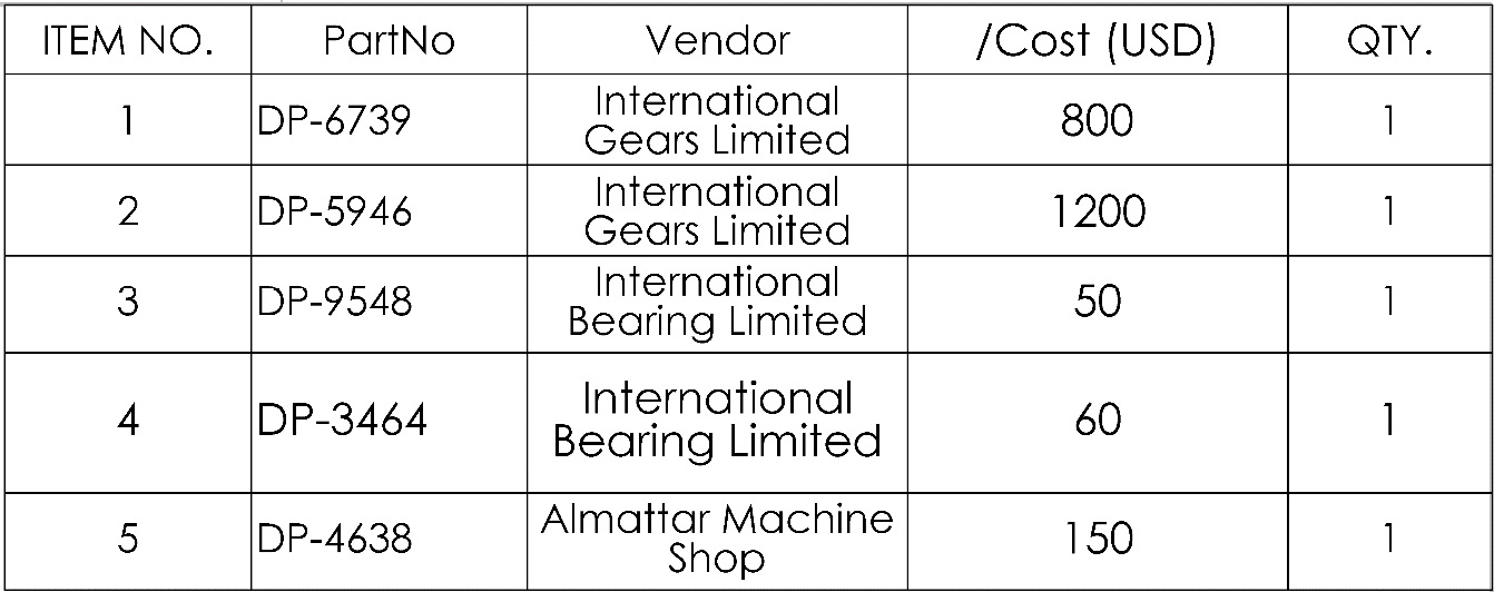
Figure 11.36 – The BOM for question 5
- Use equations to calculate the total cost for all the parts. You will end up with the following bill:

Figure 11.37 – The BOM for question 6
- Use the Auto Balloon command to link the item numbers in the drawing views. Your result will look similar to the following figure:

Figure 11.38 – The drawing and BOM for question 7
Important Note
The answers to the preceding questions can be found at the end of this book.