
Chapter 9: Introduction to Engineering Drawings
Whenever we want to communicate a specific design to others, for example, makers, manufacturers, or evaluators, a 2D engineering drawing is often required. Such drawings usually communicate the shape, materials, and dimensions of any product. This chapter will cover basic knowledge of engineering drawings and how to interpret different layouts found in them. Interpreting drawings is an essential skill for us to be able to generate our own drawings and to collaborate with other people by interpreting their drawings.
The following topics will be covered in this chapter:
- Understanding engineering drawings
- Interpreting engineering drawings
By the end of this chapter, you will have gained knowledge about different engineering drawing concepts. In addition, you will be able to interpret the different types of lines and views often found in engineering drawings.
Understanding engineering drawings
Engineering drawings are what we use to communicate designs to other entities. Whenever we produce a design for a specific product, we are often required to present an engineering drawing with it to communicate the design. Within an engineering drawing, we can communicate the shape of the design, the materials, the suppliers, and any other information we want to communicate.
Also, when engineers and technicians maintain a certain plant or a facility, they interact with engineering drawings in their day-to-day jobs. This is to identify what the machine comprises, how to maintain it, and the materials required for that. A couple of examples of engineering drawings are as follows. The following figure is of a simple part, communicating only the shape and overall dimensions of the part:

Figure 9.1 – A drawing communicating a simple part
The following figure is of a more complex assembly. Note that this drawing does not communicate dimensions; rather, it communicates the different parts included in the assembly. In other words, it communicates the bill of materials:

Figure 9.2 – A drawing showing an assembly and its bill of materials
Engineering drawings vary in complexity according to what they communicate. Also, the information displayed on a drawing sheet can vary from one organization to another. However, all drawings follow the same standards in terms of communicating different aspects of the drawing. Engineering drawings became an essential tool for communication due to their flexible distribution. They can be printed on paper or sent as images or PDFs for viewing with common software, such as an image viewer or a PDF reader.
One major element of SOLIDWORKS is drawings. These enable us to create engineering drawings for our parts and assemblies. To be able to create drawings in SOLIDWORKS, it is important for us to have some understanding of basic drawing standards and communication practices.
In this section, we have learned about engineering drawings and their purpose. Now, we can start learning about some key standards used when creating drawings to help us interpret them.
Interpreting engineering drawings
Being able to interpret engineering drawings is an essential part of creating them. In this section, we will cover essential drawing competencies, including how to interpret different types of lines and different types of drawing views. We will start by understanding lines, then views, and then projections. Interpreting drawings is a skill that grows with time as we are exposed to more drawings. We will learn about some key standards that are followed when generating drawings. Those common standards will help us interpret drawings regardless of their source.
So first, we will start by interpreting the most essential drawing element – lines.
Interpreting lines
In simple terms, we can look at drawings as different lines connected. However, the shape of a line gives it a different meaning. The following figure shows the most common types of lines found in engineering drawings:

Figure 9.3 – Common different lines found in engineering drawings
The following figure highlights a model and its 2D drawing. All the lines in the table are highlighted in the following drawing for easy reference:
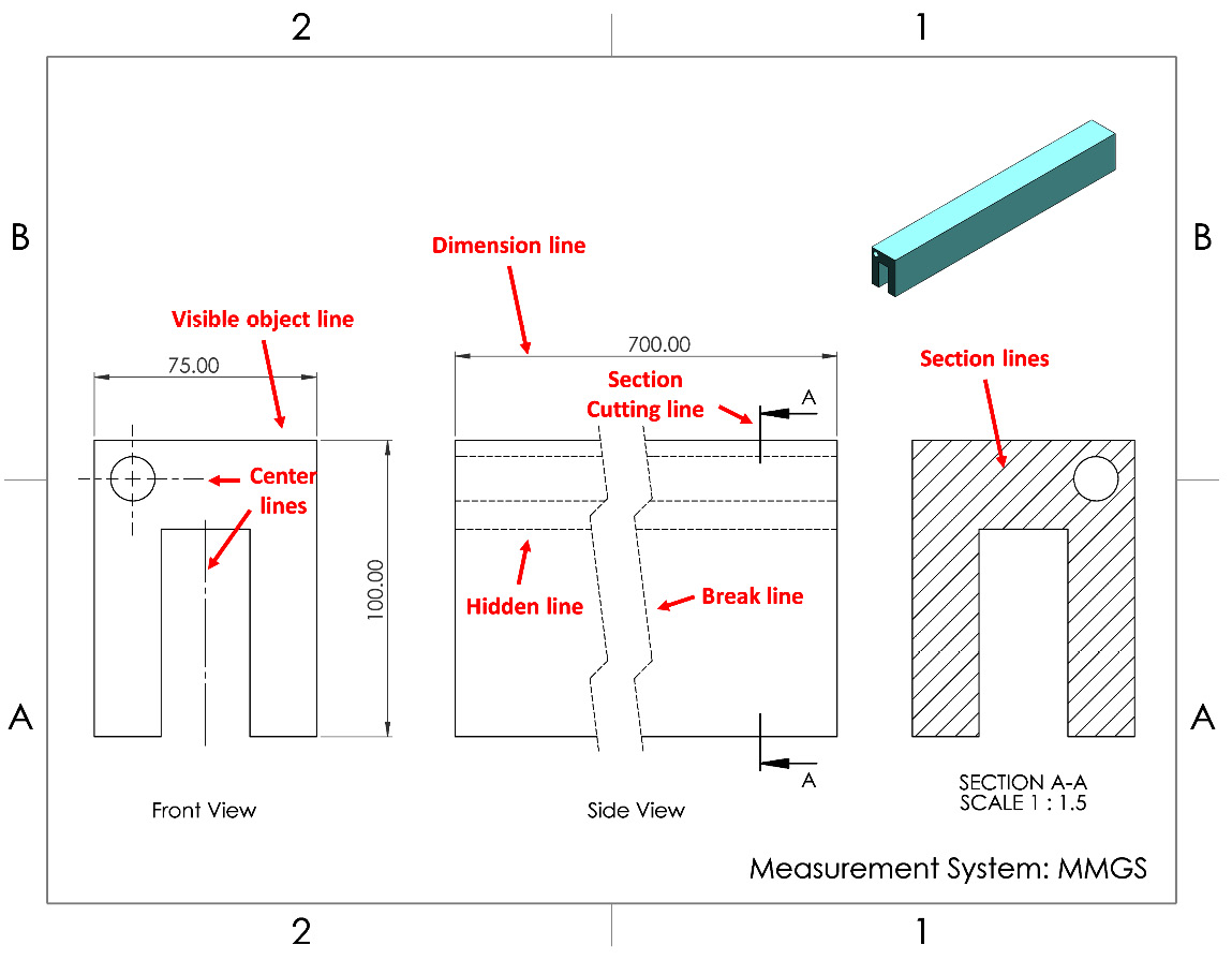
Figure 9.4 – An engineering drawing utilizing different types of lines
Note that when we create drawings with SOLIDWORKS, the software will generate all those lines according to the international standard. However, it is important for us to be able to identify the different types of lines when we see them. Now that we know how to interpret lines, we can start learning how to interpret views.
Interpreting views
In a general sense, a drawing consists of different views of a specific object. Each of the views can give us a deep insight into the shape of the object. As views are also indicated with lines, there is a lot of common knowledge between lines and views. We will look at the most common views at this level and how we can interpret them. We will briefly discuss auxiliary views, section views, detail views, broken-out section views, and crop views.
To investigate all the views, we will examine them using the following model:

Figure 9.5 – We will use this part to demonstrate the different drawing views
Using the model in Figure 9.5, we will explore the following views:
- Orthogonal views
- Auxiliary views
- Section views
- Detail views
- Broken-out section views
- Crop views
For each view, we will define its purpose and highlight how it looks in relation to the preceding model.
Orthogonal views
Orthogonal views are the most common views we will come across in engineering drawings. They are basically a combination of the front, side, top, bottom, and back views. There are two common standards in constructing orthogonal views. They are First Angle projections and Third Angle projections. Both standards are different, based on the interpretation of the top, right, left, and bottom views surrounding the base front view. The following figure shows the orthogonal view for our model on the third angle projection:
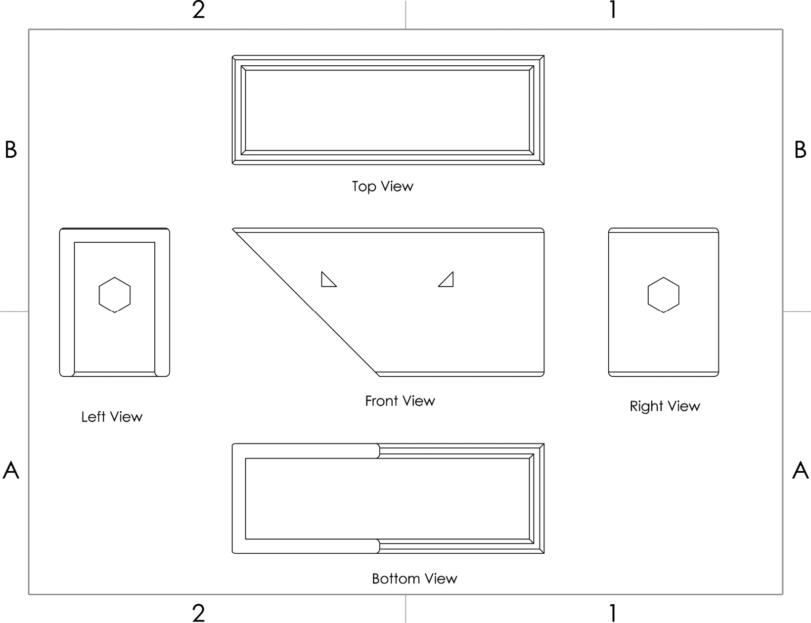
Figure 9.6 – A drawing with a third angle orthogonal view projection
The following figure shows the same orthogonal views following the first angle projection standard:
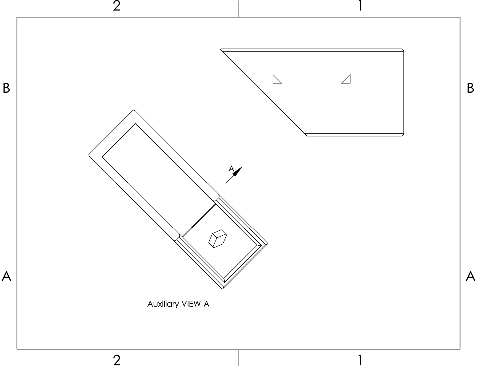
Figure 9.7 – A drawing with a first angle orthogonal view projection
The two standards are more prominent in different countries. For example, first angle projections are more common in Europe and India, while the third angle projections are more prominent in the United States of America and Japan. You can follow the link in the Further reading section at the end of the chapter for more information about those standards.
Auxiliary view
The auxiliary view shows the view of the model if we look at it from a selected surface or edge, that is, a perpendicular projection of a surface. The following figure highlights the front view of the model as well as the auxiliary view from a tilted angle. Note that the indicated arrow shows the view angle of the auxiliary view. Auxiliary views are often used to show the true size of a specific angle or to communicate specific details that are not clear enough from basic orthographic views:

Figure 9.8 – A drawing with an auxiliary view
Section views
Section views allow us to see cross sections of our models on a selected plane. This type of view allows us to see details that otherwise would be hidden from normal orthogonal views. The following figure shows the front view as well as a section view of our model.
The section line in the front view indicates where the cut was made, while the arrow indicates which side we are looking at:
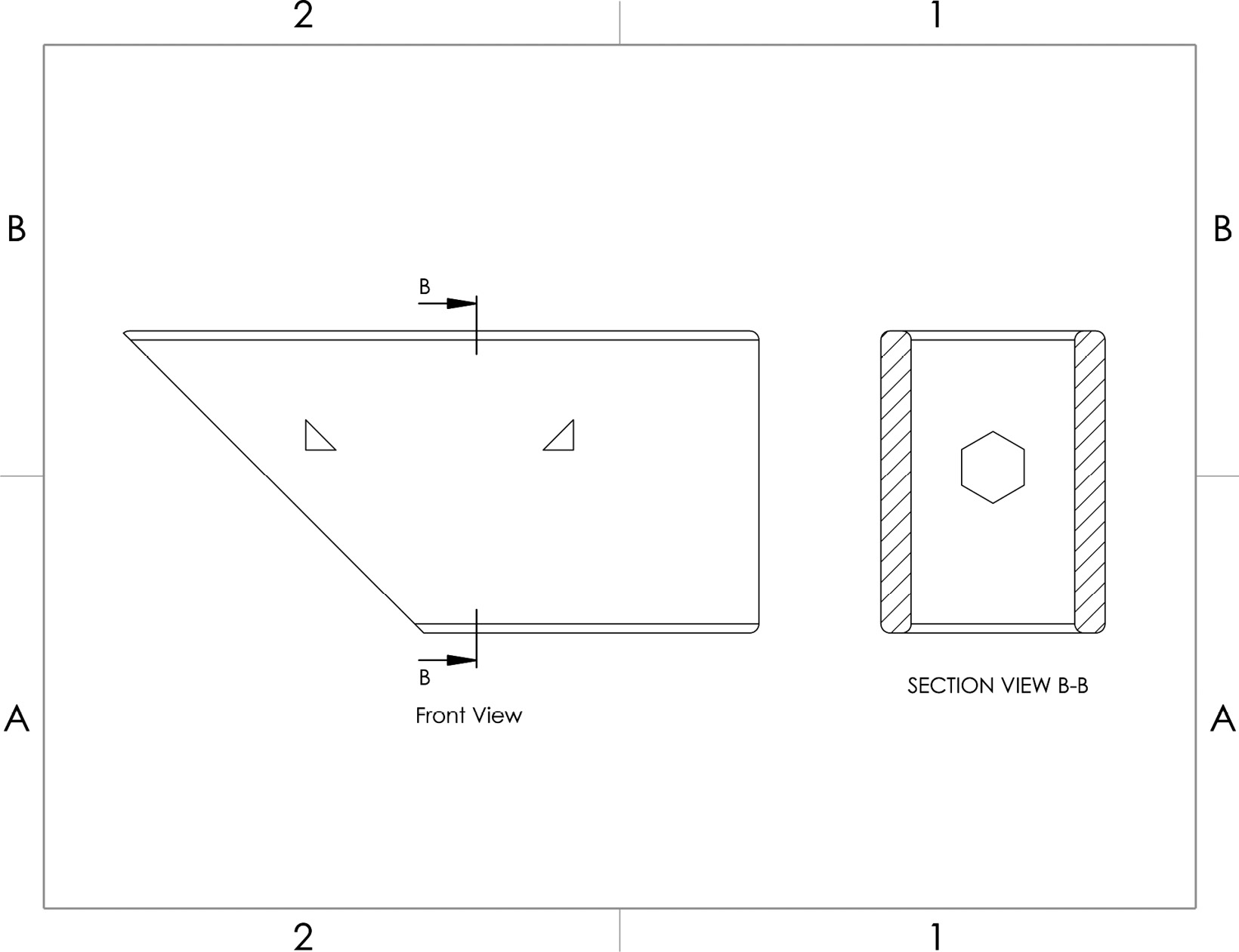
Figure 9.9 – A drawing with a section view
Detail views
Detail views allow us to see and note small details that are otherwise hard to notice. Figure 9.10 shows the front view as well as a detailed view of the small triangle:

Figure 9.10 – A drawing with a detail view
Note that the front view has a circle indicated by C to show the area/zone from where the view is taken. The same letter is used to name the view; thus, our detail view is also named C. Also, note that the detail view has its own scale to show how big it is. Generally, the detail view would have a larger scale compared to the original view.
Broken-out section views
Broken-out section views are local section views that do not require a section line. They allow us to see what is behind a specific surface. The following figure highlights the front view with and without a broken-out section.
Broken-out section views allow us to see details that are hidden from view:

Figure 9.11 – A drawing with a broken-out section view
Crop views
In a cropped view, we can crop a specific part of a drawing and show it as a standalone view. The following figure highlights the full right view of our model as well as a cropped view of it:

Figure 9.12 – A drawing with a crop view
Now that we have learned the major types of views that we will get exposed to when working with SOLIDWORKS, or when interpreting drawings provided to us, next, we will learn about axonometric projections.
Axonometric projections
Simply put, we can understand axonometric projections as 3D views of the model we are creating the drawing for – in other words, the object tilted to a certain degree in comparison to the plane of projection, which is our drawing sheet. There are three common types of axonometric projections: isometric, dimetric, and trimetric. To understand the difference between the three projections, we will examine them in relation to a simple cube. The drawings illustrate the same cube, showing the three types of projection:
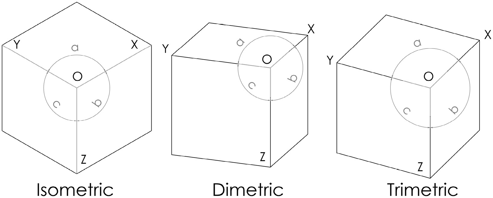
Figure 9.13 – A cube shown in isometric, dimetric, and trimetric views
Here are short descriptions illustrating the difference between the three types of axonometric projection:
- Isometric: Here, angles a, b, and c are equal. Also, lines O–X, O–Y, and O–Z are equal. This projection is the most common projection we will see and use.
- Dimetric: Here, angles a and b are equal. Also, lines O–Y and O–Z are equal.
- Trimetric: All the indicated angles and lines are unequal.
This concludes our brief introduction to axonometric projections. At the level of this book, we will not learn how to generate all of the highlighted views and projections we have covered. However, it is important for us to be able to interpret them.
Summary
Engineering drawings are essential to communicate our designs to manufacturers, maintenance teams, or any other entity. Engineering drawings not only communicate dimensions; they can also communicate materials, part specifications, tolerances, and whatever an organization/individual takes as a practice or a standard to follow. In this chapter, we learned what engineering drawings are and their purpose. We also learned how to interpret different standards related to lines and drawing views. Being able to interpret drawings is a fundamental skill for working with SOLIDWORKS. However, as with other skills, it takes time and practice to master.
Next, we will work on a 3D-modeling project to create a pair of glasses. The project will provide you with comprehensive practice of all the topics covered from the beginning of the book to this chapter.
Questions
Answer the following questions to test your knowledge of this chapter:
- What are 2D engineering drawings?
- What does the following line indicate?
Figure 9.14 – The line referred to in question 2
- What is the difference between visible object lines and dimension lines?
- What are hidden lines, what do they indicate, and what do they look like?
- What are detail views and when do we use them?
- What is a cropped view?
- In the following figure, what is the name of the view shown on the right? What is its purpose?

Figure 9.15 – The drawing view referred to in question 7
Important Note
The answers to the preceding questions can be found at the end of this book.
Further Reading
More information about the first and third angle projections in orthogonal views can be found here: https://en.wikipedia.org/wiki/Multiview_orthographic_projection.