
Chapter 7: Materials and Mass Properties
Whenever we design or model an object, we have to consider the structural materials to work with. In other words, should the object be made of steel, iron, plastic, wood, or any other materials? SOLIDWORKS provides a library with a variety of materials that we can choose from. It also provides tools that we can use to find mass properties of the object, such as the volume, mass, or center of mass of the modeled object.
The following topics will be covered in this chapter:
- Reference geometries – defining a new coordinate system
- Assigning materials and evaluating and overriding mass properties
By the end of this chapter, you will be able to assign materials to your parts and evaluate different associated mass properties. This will include finding the mass and the volume of a 3D model. We will also cover how to introduce a new coordinate system to your model. These skills will help your teams decide on what materials to choose for the products you are designing. It will also help you estimate different costs associated with materials and their related aspects, such as transportation and storage.
Technical requirements
This chapter will require that you have access to the SOLIDWORKS software.
Check out the following video to see the code in action: https://bit.ly/3dSLQNG
Reference geometries – defining a new coordinate system
By default, SOLIDWORKS provides us with one coordinate system. This system is centered on the origin. The origin is also the starting point of the three axes: X, Y, and Z. In certain cases, we require another base of a coordinate system. In this section, we will explore why we need new coordinate systems and how to define them. This will help us calculate different properties, such as the center of mass from a different perspective, which is a key skill that's required for collaborative work and a SOLIDWORKS professional.
What is a reference coordinate system and why are new ones needed?
In SOLIDWORKS, we can understand reference geometries as ones we can use as a base or as a reference for something else. For example, a plane is considered a reference geometry that we use as a base for sketches. A coordinate system is a reference geometry since we can use it as a base to determine specific locations within the canvas. In this section, we will learn what makes a coordinate system and how to define a new one in SOLIDWORKS.
In our sketch creation process, we always link our sketch to the origin. The origin is the base point for our coordinate system, which extends through the three axes: X, Y, and Z. In the lower-left corner of the SOLIDWORKS canvas, we can see the direction of the three axes:

Figure 7.1 – The indication of the axis that was found in the canvas
Using the coordinate system, we can locate any point in the canvas according to its X, Y, and Z coordinates. When in sketch mode, the lower-right corner of the canvas will show us the location of the cursor according to the X, Y, and Z locations. The following screenshot highlights where we can find these coordinates:

Figure 7.2 – The location of the cursor is indicated according to the axes below the canvas
Note
The order of the X, Y, and Z coordinates, as shown in Figure 7.2, will change according to the sketch plane.
Since SOLIDWORKS already provides us with a default coordinate system, why do we need additional ones? Here are two reasons why we may need a new coordinate system:
- To determine the coordinates according to a different coordinate system with different orientations: For example, if we measure the center of mass of an object, the measurement will be relative in the X, Y, and Z locations for the default coordinate system. With additional coordinates systems, we can determine the center of mass according to a different coordinates system of our choosing. We will explore this later in this chapter.
- To switch our views of directions: In certain applications, we may need to redefine our axes to change our sense of direction as we are creating a model. Additional coordinate systems can help us accomplish that. Also, when working with different people in a specific design, pointing toward different coordinate systems can ease communication.
We have just covered reference coordinate systems and why we may need additional ones for certain applications. Now, we will start learning how to define a new coordinate system within SOLIDWORKS.
How to create a new coordinate system
In this section, we will learn how to introduce a new coordinate system. To highlight this, we will create a simple triangular prism and introduce a New Coordinate System, as shown in the following diagram:
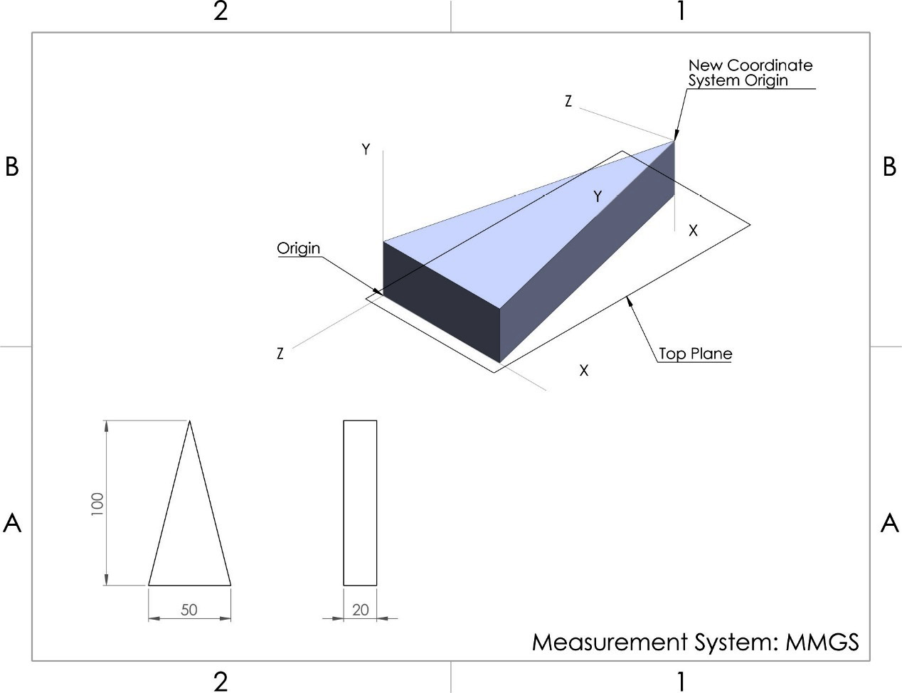
Figure 7.3 – The drawing we will build in this exercise
We will start creating this model by planning, sketching, and applying features. However, note that since we are familiar with the steps and with creating various shapes already, we will only explain this process in brief. Our plan for this model will be to start by creating the overall simple shape first and then introduce the new coordinate system. Follow these steps:
- Sketch the isosceles triangular base using the top plane and apply extruded boss with the dimensions indicated in the preceding diagram. We should have the shape shown in the following screenshot:
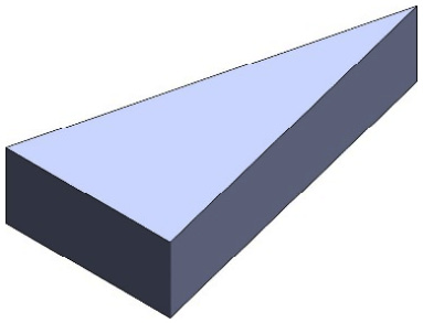
Figure 7.4 – The first step is to build the 3D model
- Under the Features tab, select Coordinate System under Reference Geometries, as shown in the following screenshot:
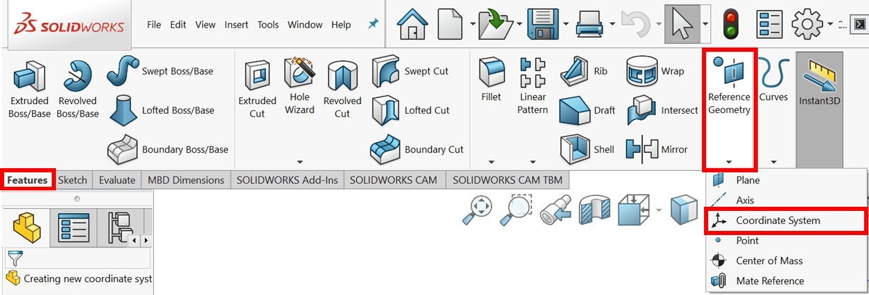
Figure 7.5 – The location of the new Coordinate System command
- PropertyManager will appear on the left, showing the options that we need to define our new Coordinate System. To define a new coordinate system, we have to specify the origin and two axes. Set the origin by selecting the indicated vertex, as shown in the following screenshot.
- We can do the same thing with X axis and Y axis by selecting edges. Note the arrows next to each axis selection of PropertyManager; they allow us to switch the direction of the axis. We can flip the direction of the axis until we get the right orientation, as shown in the following screenshot:
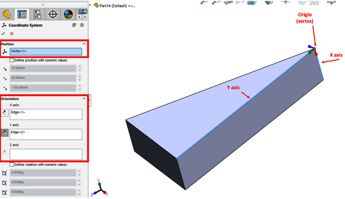
Figure 7.6 – The preview of the new coordinate system and its PropertyManager
- Click on the green checkmark to approve the new coordinate system. Once we apply the new system, it will be shown on the model as Coordinate System 1, as follows:

Figure 7.7 – The new coordinate system will be shown in the canvas after being applied
This concludes this exercise of creating the new coordinate system we needed. We will use this model again in the next part of this chapter to study mass properties. However, before moving on, let's explain the Define position with numeric values and Define rotation with numeric values options shown in PropertyManager in Figure 7.6:
- Define position with numeric values: Checking this option allows us to position the origin of our new coordinate system using numerical distance values in the X, Y, and Z axes as they relate to the absolute origin and axes. In contrast, the example we followed earlier positioned the new origin using an existing vertex.
- Define rotation with numeric values: Checking this option allows us to rotate the axes of the new coordinate system by inputting angular values concerning the absolute axes.
Both of these options can be helpful when we're looking to define a new coordinate system that is independent of the existing geometries of the part. With that, we can conclude our discussion on defining new coordinate systems. Next, we will start assigning a structural material and evaluate the mass property of our model.
Assigning materials and evaluating and overriding mass properties
Whenever we design physical objects, we have to think about what materials we will choose to build that object. These objects can be made out of plastic, steel, iron, and so on. SOLIDWORKS provides us with an array of different materials to choose from. It also provides us with the properties of each of those materials, such as their density, strength, thermal conductivity, and other properties related to the specific material. Also, once we assign a material to our model, we can evaluate the different mass properties of our objects, such as the mass and the center of mass.
In this section, we will learn how to assign materials and how to evaluate the mass properties of our models. We will also learn how to override the evaluated mass properties.
Assigning materials to parts
In this section, we will discuss how to assign specific materials to our parts. To do that, we will assign the Steel: AISI 304 material to the model shown in the following diagram. Note that we created this model earlier in this chapter, as shown in Figure 7.4.
Figure 7.8 – The 3D model we will use for material assignment
To assign materials to our model, follow these steps:
- On the design tree, right-click on the Material <not specified> entry. Then, click on the Edit Material option, as follows:
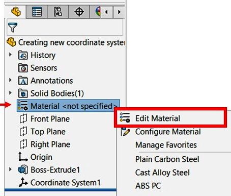
Figure 7.9 – The location of the Edit Material command
- We will see a new window containing different options, as shown in the following screenshot. On the left, we have different categories of materials to choose from. Since our material is Steel, expand that option. Note that the Steel menu may be expanded by default when you get to the following window:

Figure 7.10 – The material library with a selection of different materials to choose from
Tip
At the top of the materials list, there is a search box that can help you find the required material faster.
- Click on AISI 304. Our window will look as follows. Note the highlighted options, which show Unit of Measurement and Material Properties:

Figure 7.11 – We can choose the unit of measurement to view the material properties
Note
We can change the display unit to other units such as Imperial and Metric. This will change the unit that's displayed for the rest of the properties. The listed material properties include Mass Density, Tensile Strength, and Poisson's Ratio. We can click on other materials to find out what their properties are.
After applying the material, we will notice that the color of the part in the canvas will change to match the assigned material. For example, when assigning AISI 304 stainless steel, the visual part in the canvas will change color to light gray. We can choose not to apply the material appearance from the Appearance tab before clicking Apply.
Tip
We can add our frequently used materials to the favorite tab by right-clicking on the material and adding it to our favorites.
This concludes this section on assigning materials to our parts. We learned about the following topics:
- How to assign different materials to an existing part
- How to find different material properties for each material
At this point, we have a material assigned to our part. Next, we will learn how to view the mass of the other mass properties of our part.
Viewing the mass properties of parts
In this section, we will learn how to view the different mass properties of our existing model. To demonstrate this, we will complete the tasks shown in the following diagram. Note that this is the model from the previous section:

Figure 7.12 – The 3D model we will use to view the mass properties
In this exercise, we will complete the following four tasks:
- Find the mass of the model in grams
- Find the center of mass concerning the origin in millimeters
- Find the center of mass concerning the new coordinate system indicated in the diagram in millimeters
- Find the mass of the model in pounds
Note that all these tasks involve finding different mass properties, such as the mass and the center of mass. Hence, before we can accomplish these tasks, we need to discuss how to view the mass properties.
Viewing mass properties
To view mass properties, we can click on Mass Properties from the Evaluate tab, as highlighted in the following screenshot:

Figure 7.13 – The location of the Mass Properties command
This will show us the following window, which contains different Mass Properties related to our object. These include Density, Mass, Center of mass, Volume, Moments of inertia, and other properties. If you cannot find the Mass Properties option that's shown in the preceding screenshot, you can click on the Tools menu, and then go to Evaluate, where you will also find the Mass Properties option.
Note
The unit of measurement for the mass properties is the same as the units of measurements for the document. We will learn how to change that when we tackle the fourth task.
We will be able to find most of the information we need to resolve these tasks in the Mass Properties window. We will cover these tasks one by one:
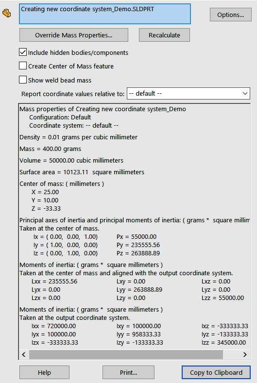
Figure 7.14 – The Mass Properties window will display different properties for the 3D model
Now, we can start accomplishing our four tasks by finding the mass of the model in grams.
Finding the mass of the model in grams
We can find the mass of the model in grams directly from the list of mass properties. Since the unit of measurement for the document is MMGS, the displayed mass is in grams. As shown in the following screenshot of the Mass Properties window, Mass is listed as 400 grams:
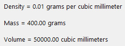
Figure 7.15 – Density, mass, and volume are among the displayed mass properties
Now, let's find the center of mass concerning the origin in millimeters.
Finding the center of mass concerning the origin in millimeters
From the Mass Properties window, we can find Center of mass: (millimeters), as shown in the following screenshot:

Figure 7.16 – Center of mass, as shown in the Mass Properties window
Note that Center of mass is a relational value. In other words, the X, Y, and Z coordinates are concerned with the origin and the default coordinate system. By default, SOLIDWORKS calculates all of the relational values concerning the default coordinate system. We can adjust that to another coordinate system, which we'll do in the next task.
Next, we will find the center of mass concerning the new coordinate system.
Finding the center of mass concerning the new coordinate system in millimeters
In this task, we need to find the same information that we found in the second task, but concerning a different coordinate system. We created the new coordinate system for the model earlier in this chapter. To change the calculations so that they relate to the new coordinate system, you can change the field next to Report coordinate values relative to to the other coordinate system, as shown in the following screenshot:

Figure 7.17 – We can evaluate the mass properties according to different coordinate systems
After selecting the new coordinate system, we will notice that the relational values, including Center of mass, will change, as shown in the following screenshot. The absolute values such as Mass and Volume are the same. Note that the new Center of mass (millimeters) is X = 10.00, Y = 64.68, and Z = 16.17, as shown in the following screenshot:

Figure 7.18 – Location-based values can change according to the coordinate system being used
Lastly, we will find the mass of the model in pounds.
Finding the mass of the model in pounds
For this task, we need to change the units of measurement for mass from grams to pounds. To do this, we can follow these steps:
- Click on Options... in the Mass Properties window, as follows:

Figure 7.19 – The location of the Options… button
- We will be taken to the Mass/Section Property Options menu, which will allow us to customize the measurement units for our mass properties. To change the mass unit, click on Use custom settings. Then, under Mass, select pounds, as shown in the following screenshot:
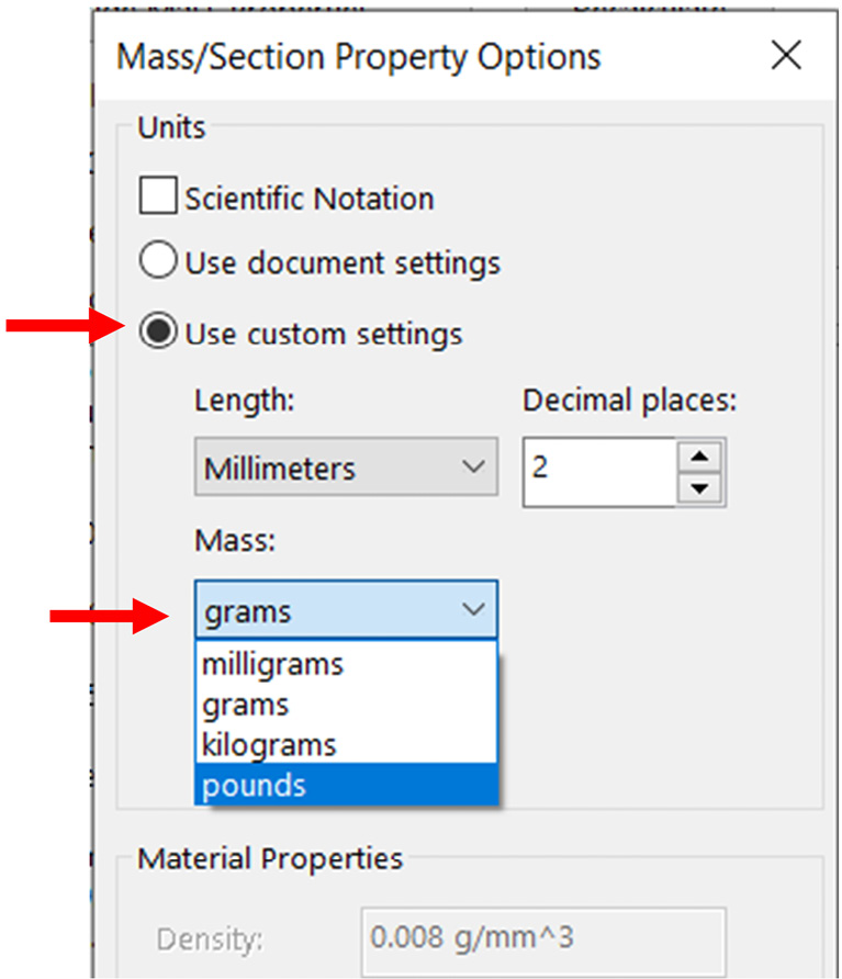
Figure 7.20 – We can change the unit of measurement that's used for the mass properties
- Click OK to confirm our unit selection. This will apply the new mass unit to the Mass Properties window, as shown in the following screenshot:
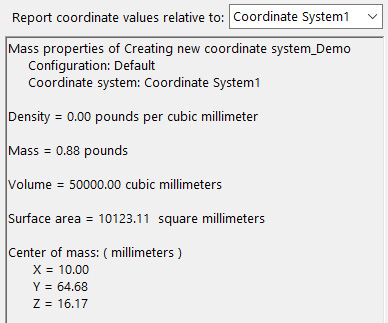
Figure 7.21 – Displayed units for mass and density switched to pounds
Note that the mass is now calculated in pounds with a value of 0.88 pounds.
Note
You can change the displayed decimal places using the same Options… window.
This concludes this section on viewing mass properties for existing models. We learned about the following topics:
- How to view the mass properties for a model
- How to adjust mass properties calculations for a new coordinate system
- How to customize the unit of measurement for mass properties evaluation
So far, we have learned how to view the actual mass properties of our parts. These are based on calculations that SOLIDWORKS does based on the geometry and the material of our part. However, we also have the option to override those values with manual entries. We will learn about this in the next section.
Overriding mass properties
In this section, we will learn how to override mass property values. By default, SOLIDWORKS calculates the mass properties based on the material that's assigned, as well as the design itself. However, in some instances, we might want to override those calculated values. For example, we might have a part in an assembly where we know its final mass but not the exact design that will result in the mass. In this case, we can simply override the mass to our required value.
To demonstrate this, we will override the mass of our model from 400 grams to 500 grams. To accomplish this, follow these steps:
- Open the Mass Properties window and click on Override Mass Properties..., as shown in the following screenshot:

Figure 7.22 – The location of the Override Mass Properties… command

Figure 7.23 – We can change the mass properties values by overriding them
This will redefine the mass as 500 grams. When viewing the mass properties, SOLIDWORKS will note the mass with the words user-overridden, as shown in the following screenshot:
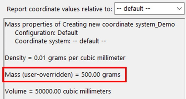
Figure 7.24 – The overridden mass will be indicated as such in the Mass Properties window
To change the mass back, we can go back to the Override Mass Properties… command and uncheck the box for Override mass. If we do this, our mass will go back to 400 grams as a calculated value. In addition to overriding the mass, we can also override the values for the center of mass and moments of inertia.
In practice, overriding the mass properties is more common when we're working with assemblies rather than parts. We do this if we want to keep a certain effect of a part in its interaction with other parts in an assembly. This is especially the case if our parts are not fully refined yet.
This concludes this section on assigning materials and evaluating mass properties. Being able to assign materials and evaluate mass properties for our model is essential in deciding what material we should use. Also, it plays an important role in calculating the cost of production, materials, transportation, and other applications that can relate to the evaluated mass properties.
Summary
In this chapter, we discussed reference coordinate systems and mass properties. We started by defining what a reference coordinate system is, why we need new ones, and how to define new ones in SOLIDWORKS. Then, we learned about mass properties.
First, we learned how to access the materials library we have in SOLIDWORKS and how to assign a particular material to our parts. Then, we learned how to find properties such as mass and volume for our models. Being able to determine mass properties will help us decide on what structural materials we can pick for the products we design. It will also help us to determine the costs associated with production, transportation, and so on.
In the next chapter, we will start working with assemblies. Assemblies are more than one part that's joined together in one file. Most of the products we use in our everyday lives, such as laptops, cars, and pens, consist of multiple parts that have been put together to form the final product or assembly. This makes these tools key to designing products that are used in our everyday lives.
Questions
Answer the following questions to test your knowledge of this chapter:
- What are coordinate systems?
- What parameters do we need to define a new coordinate system in SOLIDWORKS?
- What information do we get by evaluating the mass properties of a part?
- Create the following model and define the indicated Coordinate System 1:
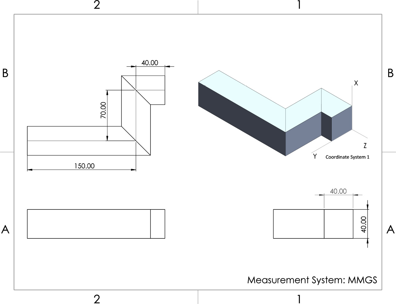
Figure 7.25 – The drawing for Question 4
- Assign the Aluminium Alloy: 1060 Alloy material to the model we created in Question 4. What is the mass in grams? What is the center of mass (in millimeters) concerning Coordinate System 1, as indicated in the preceding diagram?
- Create the following model and define the indicated coordinate system:
Figure 7.26 – The drawing for Question 6
- Assign the Plain Carbon Steel material to the model we created in Question 4. What is the mass in pounds? What is the center of mass (in inches) concerning Coordinate System 1, as indicated in the preceding diagram?
Important Note
The answers to the preceding questions can be found at the end of this book.