
Chapter 6: Basic Secondary Multi-Sketch Features
While the most basic SOLIDWORKS features require that only one sketch is made, others require more than that so that more complex shapes can be modeled. In this chapter, we will cover essential multi-sketch features, such as swept boss and swept cut, and lofted boss and lofted cut. In addition to that, we will define some new planes that are completely different than the default ones.
In this chapter, we will cover the following topics:
- Reference geometries – additional planes
- Understanding and applying swept boss and swept cut
- Understanding and applying lofted boss and lofted cut
By the end of this chapter, we will be able to create complex-looking 3D models compared to what we have built already. They will also enable us to create irregular shapes compared to the previous chapter.
Technical requirements
In this chapter, you will need to have access to SOLIDWORKS software.
Check out the following video to see the code in action: https://bit.ly/3pZxvo2
Reference geometries – additional planes
By default, SOLIDWORKS provides us with three planes that we can start sketching on. In addition, we can use any other straight surface as a plane. However, sometimes, we need planes that are different. In this case, we need to introduce our own planes. In this section, we will discuss how we can create additional planes in our 3D space. We will also introduce reference geometries.
Understanding planes, reference geometries, and why we need them
Reference geometries are like the origin points we need for the different planes that we use for sketching. They are used as a base for sketches, features, and coordinate locations. In SOLIDWORKS, reference geometries include planes, coordinate systems, axes, and points. In this section, we will focus on planes.
Whenever we create a sketch, we start by selecting a sketch plane to base our sketch on. Previously, we used the default planes and the surfaces resulting from features. However, in some cases, we may need additional planes that do not exist. To illustrate this, take a look at the following example model.
The following model consists of a cube and a cylinder that intersect. The cube is a normal cube, just like the ones we've made in the previous chapters. However, the cylindrical part has been created with an angle. In the following diagram, we used a new plane (shown as Plane 1) to sketch and create that cylinder. Note that the plane is different than the default planes and different than all of the other surfaces.

Figure 6.1 – An illustration of the default planes and an additional one
In this section, we will learn how to introduce new planes, such as the one shown in the preceding diagram. But first, we will learn about some of the geometrical principles that define a plane.
Defining planes in geometry
When defining planes in a three-dimensional space, we need to take geometrical principles into account. Hence, before we get practical with SOLIDWORKS, we need to review some of the basic geometrical principles that define a plane. As you may recall, a plane can be understood as infinity and can extend surfaces in all directions. To define a plane, we only need to define a piece of it. There are eight common ways that a plane can be defined in space. The following are the ways in which they can be defined, along with an example of each:
- Three points: Any three points in a space can be connected to define a plane, as shown in the image below:
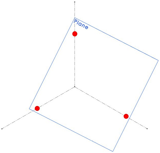
Figure 6.2 – Defining a plane using three points
- One point and a line: Linking a line to a point in space will define a plane, as shown in the image below:

Figure 6.3 – Defining a plane using a point and a line
- Two parallel lines: Any two parallel lines in a space can define a plane, as shown in the image below:
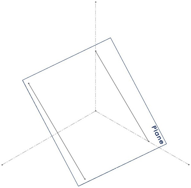
Figure 6.4 – Defining a plane using two parallel lines
- Two intersecting lines: Any two intersecting lines can define a plane, as shown in the image below:
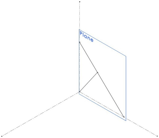
Figure 6.5 – Defining a plane using two intersecting lines
- Other planes: Any existing plane or flat surface can be used to define new planes if we offset it by a certain distance. We can also make the new plane related to the other two. For example, the new plane can be midway between two parallel planes or flat surfaces. The image below highlights a base plane and another plane defined by an offset:
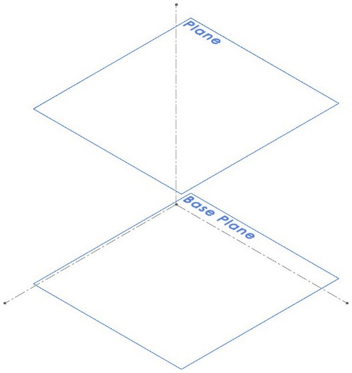
Figure 6.6 – Defining a plane using another plane
- A plane and a line: Mixing an existing plane and a line can result in a new plane. This is done by defining a relationship between the existing plane and a line. These relations can be parallel, perpendicular, or coincident. We can also place an angle or distance between them, as shown in the image below:
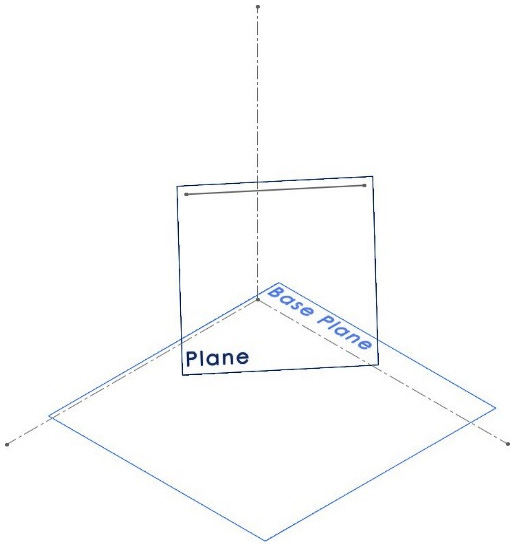
Figure 6.7 – Defining a plane using another plane and a line
- A plane and a point: A plane can define another plane if we offset it. A point can be used to define the offset, as shown in the image below:
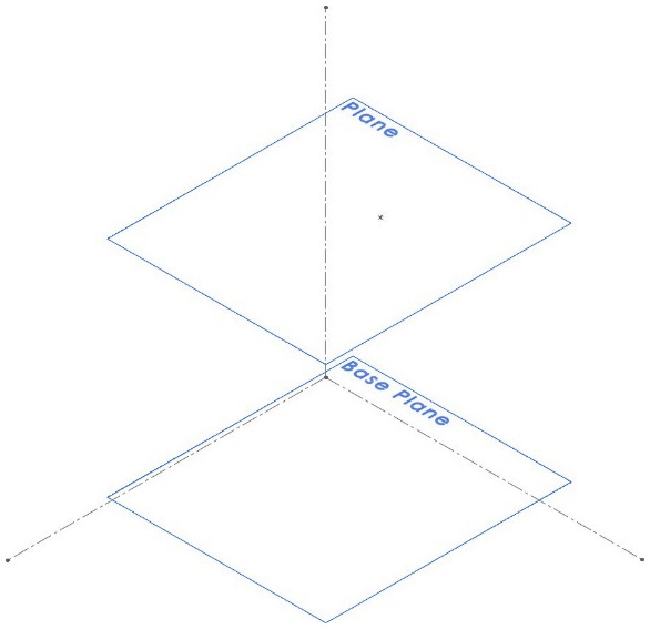
Figure 6.8 – Defining a plane using another plane and a point
- A plane and a curve: Curve tangents can be used to define planes when we wish to relate the new plane to an existing one, as shown in the image below:
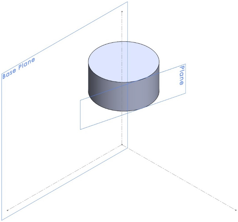
Figure 6.9 – Defining a plane using another plane and a curved surface
Note that these are just the basic ways of defining planes in a space. In most cases, we can manipulate angles, distance, and geometric relations further to generate more diverse planes.
Once we are familiar with how to define a plane from a geometrical perspective, we can easily define a plane in SOLIDWORKS by selecting the different components to define it with. Now, we will learn how to define new planes in SOLIDWORKS.
Defining a new plane in SOLIDWORKS
Now that we know how to define planes in different ways in terms of geometry, we can start learning how to define new planes in SOLIDWORKS. To illustrate this, we will create the following model:
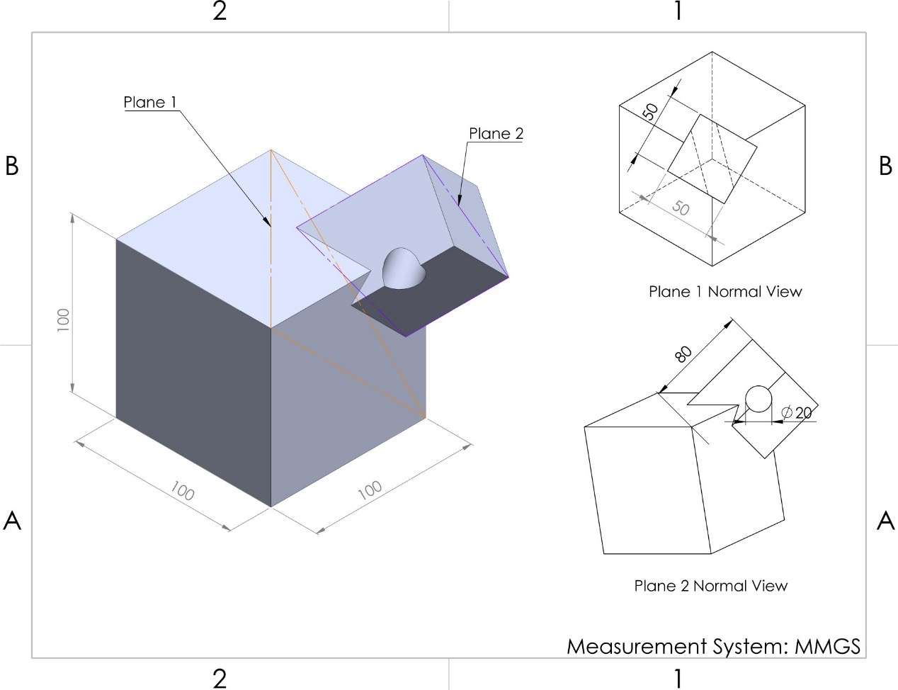
Figure 6.10 – The 3D model we will make in this exercise
Note that, in the preceding model, we have used two additional planes: Plane 1, which is in orange, and Plane 2, which is in purple. They are defined as follows:
- Plane 1: Three points (vertexes)
- Plane 2: Two parallel lines (edges) that come from the side extrusion
To create this model, we need to plan, sketch, and apply features. However, we will also create additional reference planes.
Our plan is to create the base cube first and then create a new reference plane. After that, we'll create the side extrusion using the new plane. Then, we'll create the second reference plane. Finally, we'll create a circular hole. Let's start applying this plan by following these steps:
- Create the base 100 mm cube. We will get the following model by doing so:
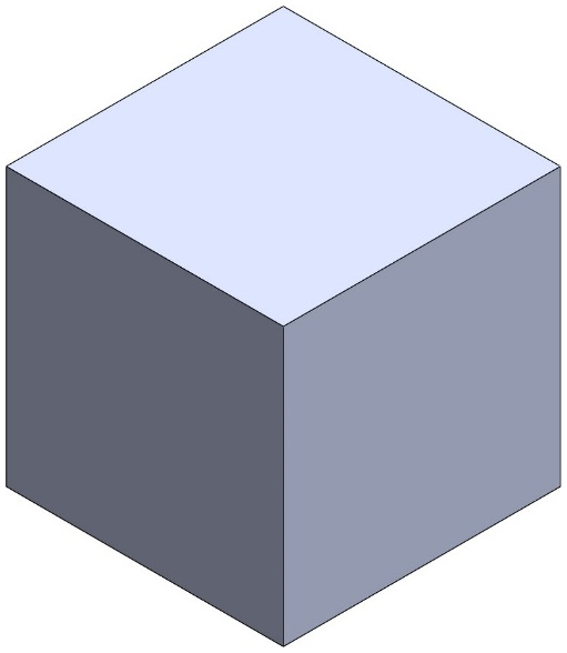
Figure 6.11 – The first step will be to create a 100 cube
- Now, we can start creating the first reference plane for our model. With the Features tab selected, click on the Reference Geometry tab and select Plane, as follows:
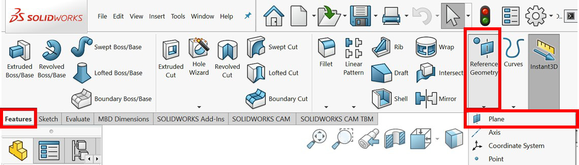
Figure 6.12 – The location of the Reference Geometry command
- The PropertyManager panel will appear on the left-hand side so that we can select our references. Select three points (vertexes), as shown in the following screenshot. Also, you may need to check the last box under Options, that is, Flip normal, since we want the normal dimension to be outward, as indicated by the blue arrow. We will get the following preview:
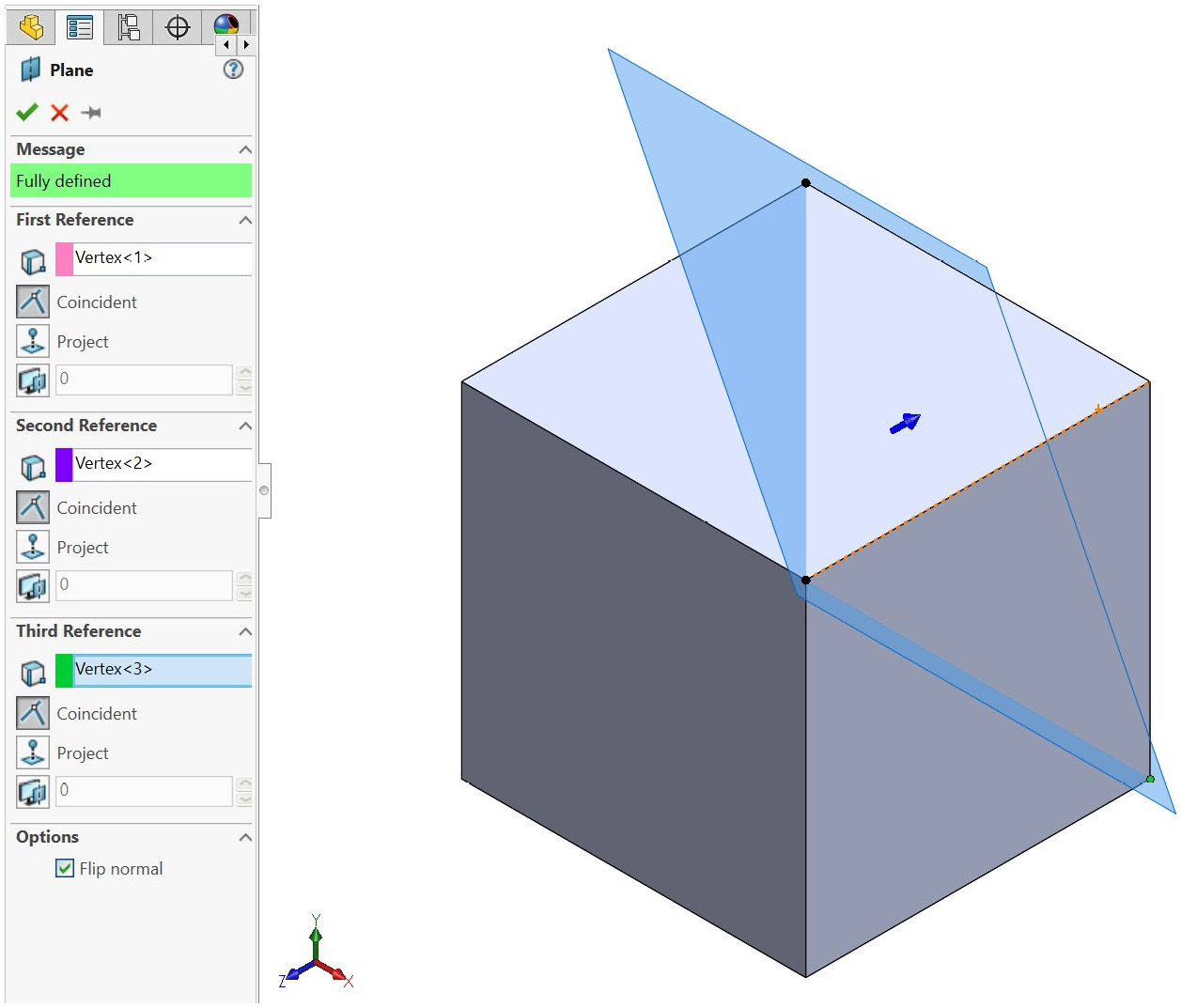
Figure 6.13 – PropertyManager and the plane preview
The options for reference planes are simple. First, we need to select a reference. The reference could be a point, a plane, or a straight or curved surface. Then, we can select the relation of our new plane to that reference.
In the case of the plane we are creating, the first, second, and third references are all points. Also, the relation of these points to the new plane is that they are all coincident.
Note
We do not always need three references; the number of references depends on how we define the plane, as we explained in the Defining planes in geometry section. On top of these options, we will be told whether the plane is fully defined.
- Click on the green checkmark to approve the plane.
- We can now start sketching on top of the new plane we just created. In terms of sketching, we can treat the new plane just like the other default planes we have. Select the new plane from the design tree and sketch a 50 mm square that's centered on the edge of the cube, as follows:
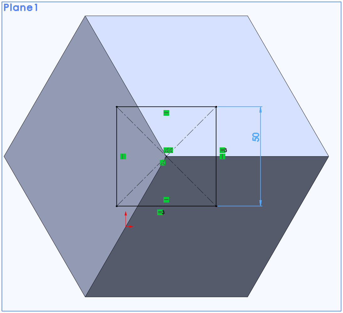
Figure 6.14 – Using the new plane to create new sketches
- Apply a feature based on the new sketch. We can apply features to new sketches in the same way we apply features to other sketches: based on default or surface planes.
- Apply the extruded boss tool by extruding the shape by 80 mm. We will get the following shape:

Figure 6.15 – Features can be applied based on sketches from the new planes
- Now, we will create the second reference plane, which is based on two parallel lines. Select the geometries and select the two parallel edges, as shown in the following screenshot. Then, click on the green checkmark to generate the new plane.

Figure 6.16 – The PropertyManager and preview for our second plane
- Sketch the new circle with a diameter of 20 mm, as shown in the following screenshot. Note that the center of the circle is located mid-point on the edge.
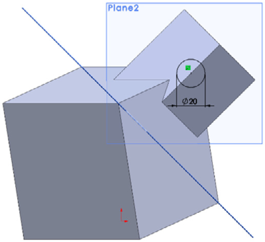
Figure 6.17 – A new circle sketch applied on a new plane
- Apply the extruded cut feature by setting the end condition to be Through all- both. We are doing this since the hole goes through the whole model and in both directions. We will get the following shape:

Figure 6.18 – The final shape of our 3D model
This concludes the process of creating the model.
Note that, in our resulting model, we can see that the two planes we introduced are visible. To make the model look cleaner, we can hide the new planes after they have fulfilled our needs. We can do this by right or left-clicking on the plane listing in the design tree and selecting the eye-shaped option, as shown in the following screenshot:
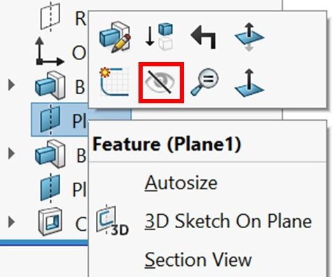
Figure 6.19 – The hide option to hide planes from view
Once we've hidden the visible planes, our cleaner model will look as follows:

Figure 6.20 – A clean-looking 3D model after hiding the new planes
In this exercise, we created a reference plane with three points and two parallel lines. If we were to create a new plane based on any of the other six methods, we looked at earlier, for example, another plane, or two intersecting lines, we can simply follow the same steps. The only difference will be the reference selection and the available selected reference relations.
This concludes how to create planes as additional reference geometries in SOLIDWORKS. In this section, we covered the following topics:
- How to access the command for creating new reference planes
- How to create a reference plane based on three points
- How to create a reference plane based on two parallel lines
- How to use a new reference plane to create sketches and features
Now that we know how to generate new plane reference geometries, we can start learning about our next set of features: swept boss and swept cut.
Understanding and applying swept boss and swept cut
Swept boss and swept cut allow us to create shapes by sweeping a profile along a path. In this section, we will discuss swept boss and swept cut in detail. These features are opposites and require more than one sketch if we wish to apply them. We will learn about their definitions, how to apply them, and how to modify them.
What are swept boss and swept cut?
Swept boss and swept cut are opposing features; one adds materials, while the other removes materials. Let's talk about them in more detail:
- Swept boss: This adds materials by sweeping a profile shape on a designated path.
- Swept cut: This removes materials by sweeping a profile shape on a designated path.
The following diagrams highlight the effect of the swept boss and swept cut features in a better way:

Figure 6.21 – An illustration of what the Swept Boss feature does
The preceding diagram shows Swept Boss, while the following diagram shows Swept Cut. Note that both features require two sketches before they can be applied:
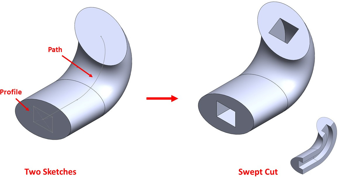
Figure 6.22 – An illustration of what the Swept Cut feature does
Compared to the extruded boss and extruded cut, swept boss and swept cut provide us with more flexibility when it comes to extruding a shape. While extruded boss and extruded cut add and remove materials directly perpendicular to the sketch plane, swept boss and swept cut allow us to guide the extrusion as we see fit. Let's start applying them, beginning with swept boss.
Applying swept boss
In this section, we will demonstrate how to apply the swept boss feature. To do this, we will create the model shown in the following diagram:
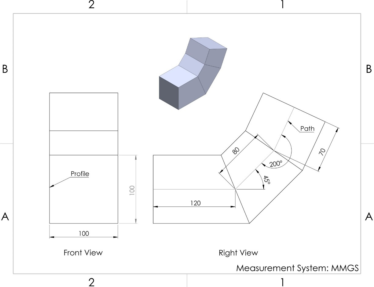
Figure 6.23 – The 3D model we will build for this exercise
To model this shape, we will go through the stages of planning, sketching, and applying features. Our plan will be to create a rectangular profile and then the path. After that, we will apply the swept boss feature. Follow these steps to do so:
- Select front plane and draw a square centered at the origin. This will represent the profile. Set the side length to 100 mm, as shown in the following diagram. Then, exit sketch mode.
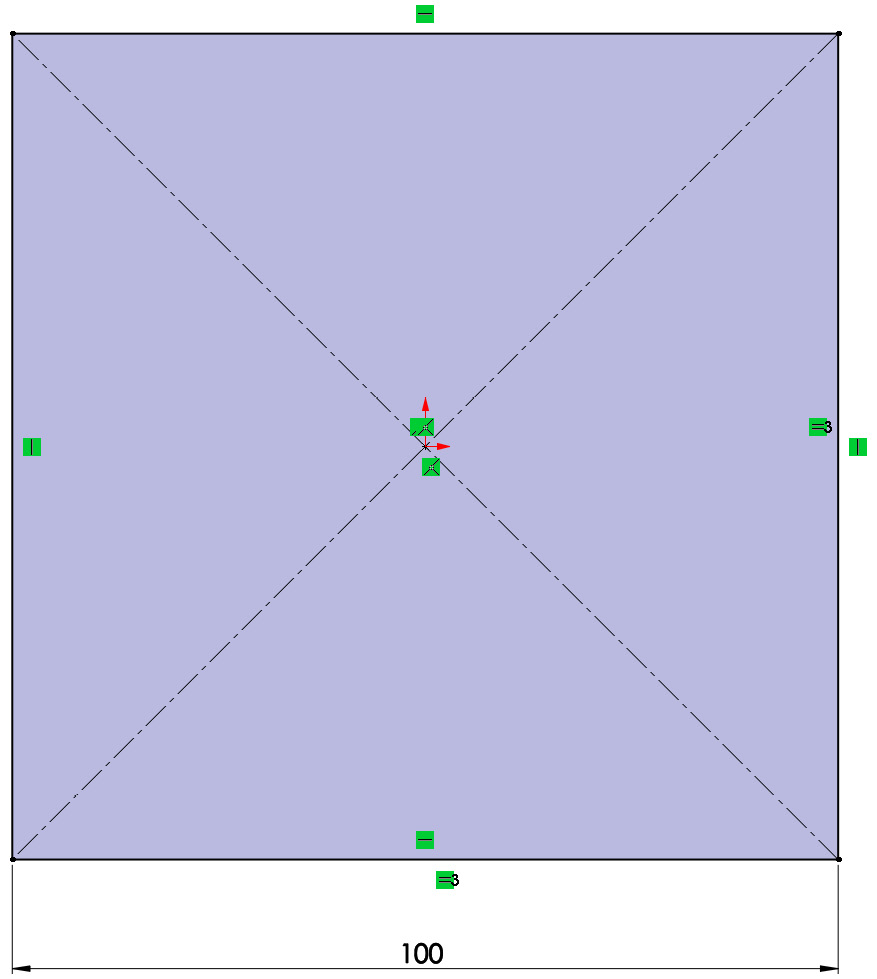
Figure 6.24 – The profile sketch of a 100 mm square
- Select right plane and draw the path that's shown in the right-hand view of our diagram. We can make the start of the path the origin. Our sketch should look as follows. Exit sketch mode after that.

Figure 6.25 – The path sketch
- Now, we will apply the swept boss feature. Go to the Features tab in the command bar and select the Swept Boss/Base command, as highlighted in the following screenshot:

Figure 6.26 – The location of the swept features
- PropertyManager will appear on the left-hand side so that we can select Profile and Path. We can then make the following selections:
a) Profile: Select the first rectangle we drew in step 1. We can select it by clicking on it on the canvas.
b) Path: Select the curve we sketched in step 2.
Once we've selected Profile and Path, we will see a preview of our shape, as shown in the following screenshot:

Figure 6.27 – PropertyManager and a preview of the swept boss feature
- Click on the green checkmark to approve this feature. This will give us the final shape, as shown in the following screenshot:

Figure 6.28 – The resulting 3D model after applying swept boss
This concludes using the swept boss feature. Before we move forward with swept cut, let's talk about one of the aspects of the path and explain some of the other options that are available for the swept boss feature.
Note that for basic sweeps, the path must either intersect the profile itself or its extension so that it's captured by the feature. In the following screenshot, we have highlighted different types of acceptable and unacceptable paths. The unacceptable paths are indicated with an X sign.
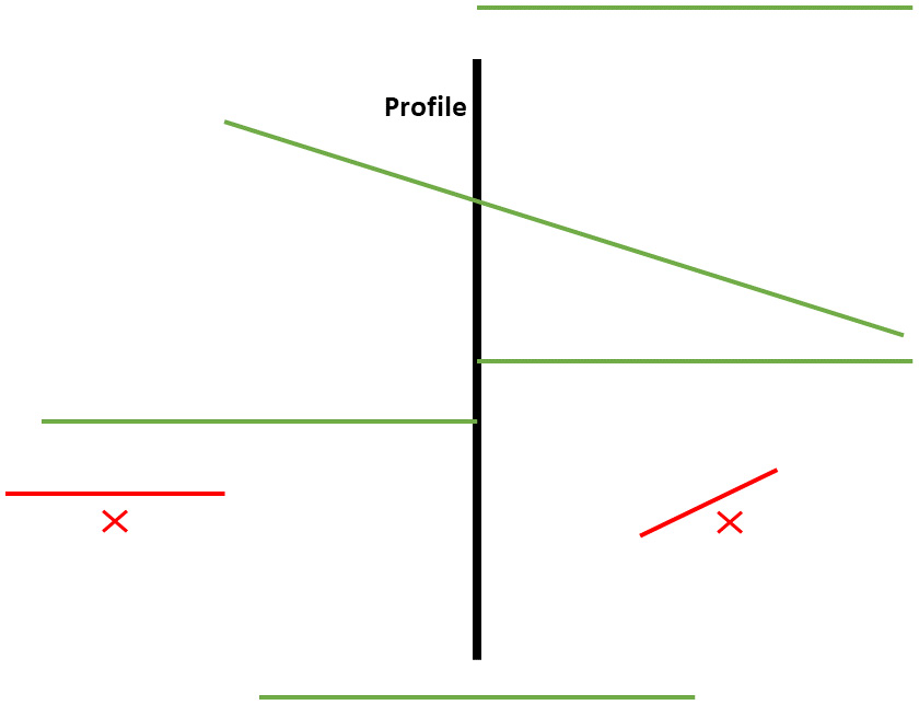
Figure 6.29 – An illustration of the acceptable paths location for the swept features
Now that we know how to create a basic swept boss, we can discuss the different options we can use to create more complex swept boss applications.
Swept boss feature options
Now, let's examine some of the other options that are available with the swept boss feature that we didn't utilize in the previous exercise. We will cover the options we missed from top to bottom, as shown in the following screenshot:

Figure 6.30 – The PropertyManager swept feature showing many options
The following is a brief explanation of these options:
- Circular Profile: Under Profile and Path, we can select the Circular Profile option. This makes it easier for us to create the swept feature when the profile is circular and goes through the middle of the path. When selecting the circular profile option, a profile sketch will not be needed.
- Guide Curves: With this option, we can add more sketches to help to guide our swept boss feature. This is helpful when the swept boss feature does not have a regular shape that matches the profile. However, it is an advanced feature that we will not use at this level.
- Profile orientation: This helps us to determine how the profile moves with the path. There are two options available here:
a) Follow Path: This will make the profile tilt along with the path.
b) Keep Normal Constant: This will keep the profile facing the same direction as it moves on the path.
- Profile Twist: This can be used to create shapes such as spiral springs or any type of twisted shape since it will allow the profile to twist around the path. The following screenshots are examples of using Profile Twist in two different ways. One was done by twisting a square by 90 degrees, as follows:

Figure 6.31 – A resulting sweep with the profile twist option
The other was done by twisting a circle by three revolutions around the path, as shown in the following screenshot:

Figure 6.32 – The Profile Twist option can also be used to create spirals
- Start and End Tangency: This ensures that the sweep is normal for the path toward the start or endpoint.
- Thin Feature: This will allow us to only sweep boss a thin layer around the profile instead of the whole enclosure. This is similar to the thin feature option in the extruded boss feature.
- Curvature Display: This option allows us to analyze the curvature of our swept feature better. This is done by adding visual elements such as mesh preview, zebra stripes, and curvature combs.
This concludes this exercise, which was all about applying the swept boss feature. We covered the following topics in this section:
- How to create sketches that can use swept boss
- How to apply the swept boss feature
- The acceptable paths that can be used with the swept boss feature
- The different options that can be used with the swept boss feature
Now, we can start learning about the opposite of swept boss, that is, swept cut.
Applying swept cut
In this section, we will demonstrate how to use the swept cut feature. To do this, we will create the model shown in the following diagram by adding a swept cut to the model we created earlier:
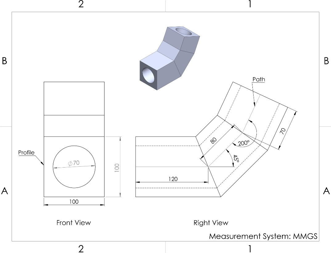
Figure 6.33 – The 3D model we will build in this exercise
To model this shape, we will go through the procedure of planning, sketching, and applying the feature. Our plan will be to create the profile on our existing swept boss. After that, we will apply the swept cut feature by following the same path we had for the swept boss. To act on this plan, we will follow these steps:
- Select the face shown in the front view as a sketch surface. Then, sketch a circle with a diameter of 70 mm, as shown in the preceding diagram. The sketch will look as follows. Exit sketch mode afterward.
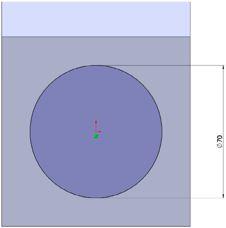
Figure 6.34 – The profile sketch
Note
The path for this cut is the same path that we used to apply the swept boss feature. Hence, we don't need to create another path. Instead, we can reuse the one we already have. A reused sketch will be indicated in the design tree with a small icon of an open hand.
- Now, let's apply the swept cut feature. From the Features tab, select the Swept Cut command, as shown in the following screenshot:

Figure 6.35 – The location of the Swept Cut feature
- Select the appropriate profile by selecting it from the canvas, just like we did with the swept boss feature.
- We can select the path from the design tree that appears on the canvas. Expand that Design Tree and look for the Sketch we used for the Path under the Sweep feature. Then, select the sketch that corresponds to the path, as shown in the following screenshot. We will see a preview of the swept cut feature.
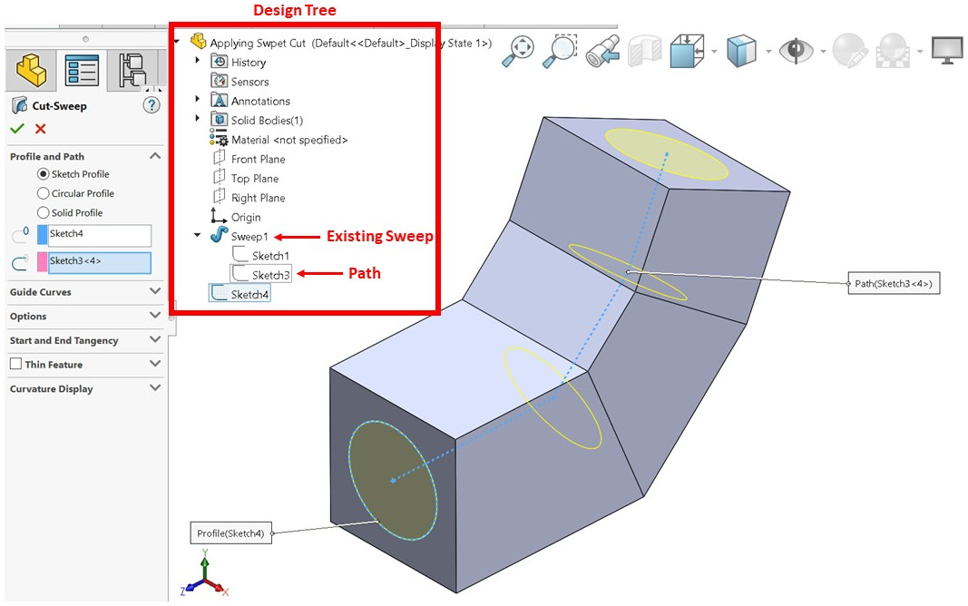
Figure 6.36 – The design tree can be used to select sketches for the path or profile
- Click on the green checkmark to apply the swept cut feature. This will result in the following model:
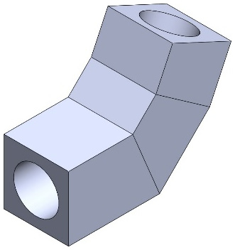
Figure 6.37 – The final 3D model after applying the swept cut
This concludes this exercise, which was all about applying the swept cut feature. The additional options that are available for the swept cut feature are the same as those for the swept boss festure. We covered the following topics in this section:
- How to apply the swept cut feature
- How to reuse a sketch in more than one feature
Now that we know how to apply the swept boss and swept cut features, we need to know how we can modify them.
Modifying swept boss and swept cut
Modifying features in SOLIDWORKS is done in the same way that it's done for all features; that is, by right- or left-clicking on the feature in the design tree and selecting Edit Feature. In addition to editing the feature, we can also edit the sketches that are guiding the feature. In the case of the swept boss and swept cut features, this includes the profile and path sketches. To demonstrate this, we will modify our previous model so that it looks as follows. These modifications have been annotated.
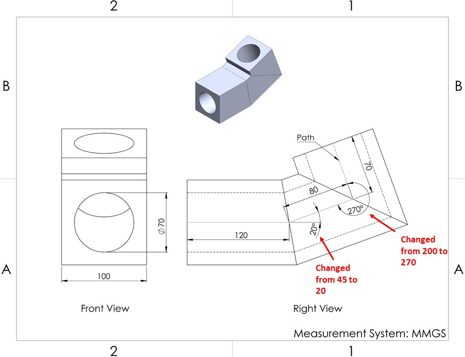
Figure 6.38 – The modifications we will apply for this exercise
Note that this model is very similar to the one we created in the previous exercise. The only difference is the path. Hence, we will only modify the sketch we used for the path. To do that, follow these steps:
- Find the sketch path in the design tree by expanding the design tree listing of the sweep boss feature. Right-click on the path sketch and select Edit Sketch, as highlighted in the following screenshot. Note that if a sketch is being used in more than one sketch, a small hand icon will appear next to it.

Figure 6.39 – We can edit sketches from the design tree
- Adjust the sketch by double-clicking on the angle values and changing them so that they read as follows:
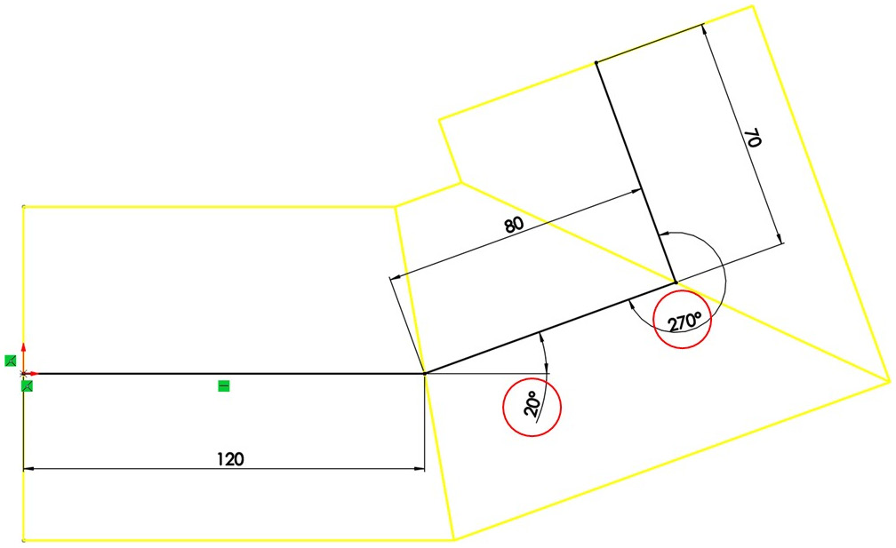
Figure 6.40 – We can adjust the sketches in the canvas once selected from the design tree
- Exit sketch mode. You will see that the model now looks as follows. Note that, by editing the sketch, we ended up editing the swept boss and swept cut features since both are utilizing the same sketch.
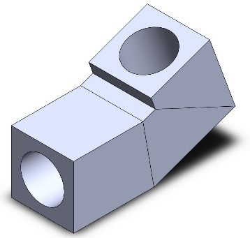
Figure 6.41 – The final 3D model after modifying the path sketch
Tip
A shortcut to edit the dimension is to double-click on the sketch from the design tree and then adjust the displayed dimensions directly without getting into edit mode.
This concludes our exercise on editing swept boss and swept cut. In this section, we covered the following topics:
- How to edit sketches that are being used for the swept paths
- How to identify sketches in the design tree that are being used in more than one feature
In this section, we covered how to apply and modify the swept boss and swept cut features. Next, we will cover another set of features: lofted boss and lofted cut.
Understanding and applying lofted boss and lofted cut
Lofted boss and lofted cut allow us to create a shape by sketching sections of it. In this section, we will discuss the features of the lofted boss and lofted cut. These features are opposites, and so we require more than one sketch if we wish to apply them. We will learn about their definitions, how to apply them, and how to modify them.
What are lofted boss and lofted cut?
With lofted boss and lofted cut, we are able to add or remove materials based on multiple cross sections. Let's talk about them in more detail:
- Lofted boss: This adds materials by linking different cross sections together. This includes the start and end of the shape. If we choose to, we can link these cross- sections with guide curves.
- Lofted cut: This removes materials by linking different cross sections together. This includes the start and end of the cut shape. If we choose to, we can link these cross sections with guide curves.
These features are polar opposites: one adds materials, while the other removes materials in the same way. The following diagrams illustrate these features:
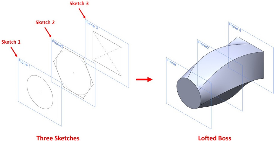
Figure 6.42 – An illustration highlighting the Lofted Boss feature
The preceding diagram shows Lofted Boss, while the following diagram shows Lofted Cut. Note that both features require at least two sketches if we wish to apply them. We can add as many sketches as we wish in order to define the sections:
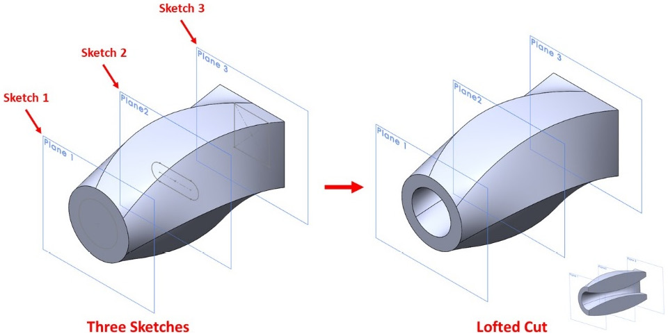
Figure 6.43 – An illustration highlighting the Lofted Cut feature
Lofted boss and cut can provide us with a unique way of controlling how we add or remove materials compared to other features, such as swept boss and swept cut and extruded boss and extruded cut. Now that we know what lofted boss and lofted cut are used for, we can start applying them. Let's start by applying a lofted boss.
Applying lofted boss
In this section, we will cover how to apply the lofted boss feature. To illustrate this, we will create the model shown in the following diagram:
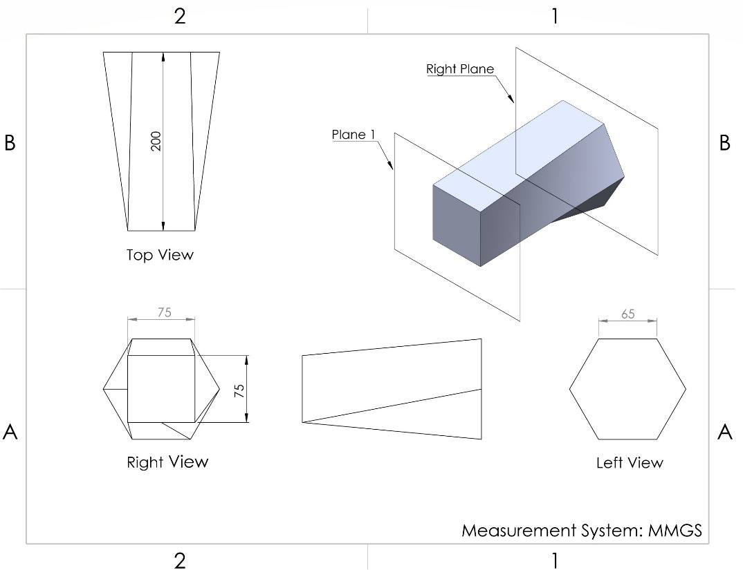
Figure 6.44 – The 3D model we will build in this exercise
To create this model, we will go through the steps of planning, sketching, and applying features. Our plan will be to utilize two planes to create two sketches and then apply the lofted boss feature. In this exercise, we'll have to create one additional reference plane based on the default right plane. Let's start by following these steps:
- The first step is to define our new reference planes. Select the Plane sub-command, which can be found under Reference Geometries. Then, create Plane 1 by offsetting a distance of 200 mm from Right Plane, as shown in the top view of the diagram. The option for plane creation is shown in the following screenshot, and can be found alongside the final shape of the two planes:

Figure 6.45 – PropertyManager for our new plane
After approving the new plane, it will appear parallel to Right Plane, as shown in the following diagram:

Figure 6.46 – The new plane after being defined
- Since we are using the lofted boss feature, we will create two different sketches in the two planes. Select Plane1, which we created previously, and sketch a square whose sides are equal to 75 mm, as shown in the right-hand view of the preceding drawing. The resulting sketch will look as follows. Exit sketch mode after that.

Figure 6.47 – A 75 mm square sketched on plane1 representing our first profile
Tip
You can show Right Plane in the canvas by right- or left-clicking on it in the design tree and selecting Show.
- Select the right plane and sketch a hexagon whose sides are equal to 65 mm, as shown in the left view of the diagram. The resulting sketch will look as follows. Exit sketch mode after that.

Figure 6.48 – A hexagon sketched on the right plane representing our second profile
- Now, we will apply the lofted boss feature to connect the two sketches. Select the Lofted Boss/Base command from the Features tab, as shown in the following screenshot:

Figure 6.49 – The location of the Lofted Boss feature
- After selecting the command, we will get the command's PropertyManager options on the left-hand side, as shown in the following screenshot:
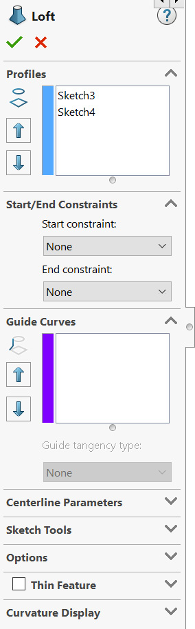
Figure 6.50 – PropertyManager showing the profile selection
For the profiles, select the square first, then the hexagon. Note that the selection is order-sensitive. Once we do that, we will get the following review on the canvas. Note that there is one guideline in the preview to help us to define our loft. This line is controlled by the two green endpoints. To adjust it, we can drag the point to another location. This will change the shape of the loft. Take your time and adjust the guideline so that it looks as follows:
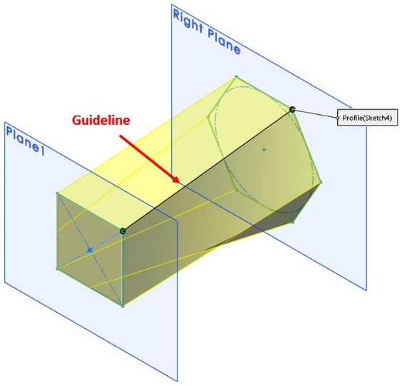
Figure 6.51 – A preview of the lofted boss showing a guideline
Note
The initial positioning of the guideline is determined by where you click on the sketch to select the profile.
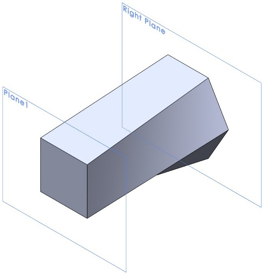
Figure 6.52 – The final resulting shape after applying the lofted boss
This concludes our exercise on the lofted boss feature. In this exercise, we only covered the most basic lofted shape. However, this feature has many advanced options that we did not get around to using. We will explore these options next.
Lofted boss feature options
In the feature's PropertyManager, we will be able to find all of the feature's options. The following screenshot highlights PropertyManager for the lofted boss feature:

Figure 6.53 – The Lofted Boss PropertyManager showing the available feature options
The following is a brief explanation of these options:
- Start/End Constraints: This gives us more control over the areas that are close to the profile sketches. Under each, we have the following options:
a) Direction vector: This pushes the loft toward a specific direction, as per an existing vector. To apply this, we may need to create additional lines to push the loft.
b) Normal to profile: This pushes the loft in a direction that's normal/perpendicular to the existing profile we used to build the loft.
- Guide Curves: This gives much more flexibility in terms of how the loft is constructed. However, we still need to create more curves from different sides to guide the loft. The following screenshot shows our previous loft with multiple guiding curves:

Figure 6.54 – An illustration of the guide curves function
- Thin Feature: This changes the loft so that it's only lofting the shell rather than the whole shape.
This concludes the various options of the lofted boss feature. In this section, we covered the following topics:
- How to create different profiles with the lofted boss feature
- How to apply the lofted boss feature
- The different options for the lofted boss feature
Now that we know how to apply the lofted boss feature, we can start learning how to apply the lofted cut feature.
Applying lofted cut
The lofted cut feature works the same as the lofted boss feature, except that it has the opposite effect. To show you how this feature works, we will build on the previous model and create the model shown in the following diagram:

Figure 6.55 – The 3D model we will build in this exercise
Note that, for this model, we will only create an internal cut from the previous model. This cut is governed by two circles on each end. Like we did previously, we will create the model by planning, sketching, and then applying features. We will use the existing end faces for our shape to sketch two circles. Then, we will apply the lofted cut feature. Follow these steps to implement this plan:
Tip
Since both of our sketches are located on existing faces, we can hide the two visible planes and sketch on the faces that have been formed from the features instead. To hide a plane, we can right-click on it from the design tree and select the Hide option, which is the small eye icon.
- Select the square face as a sketch plane and sketch a 50 mm circle, as shown in the following diagram. Use the origin as the center of the circle. Exit sketch mode after that.
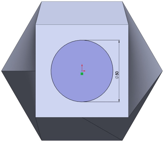
Figure 6.56 – The sketch of our first profile
- Select the hexagonal face as a sketch plane and sketch a 100 mm circle, as shown in the following diagram. Use the origin as the center of the circle. Exit sketch mode after that.
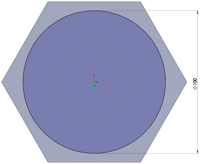
Figure 6.57 – The sketch of our second profile

Figure 6.58 – The location of the Lofted Cut command
- The PropertyManager options for the lofted cut are the same as they are for the lofted boss feature. Under Profiles, select the two circles we sketched earlier. We will get the following preview. Note that since our two profile sketches are circles, the guideline provided will not have an effect.
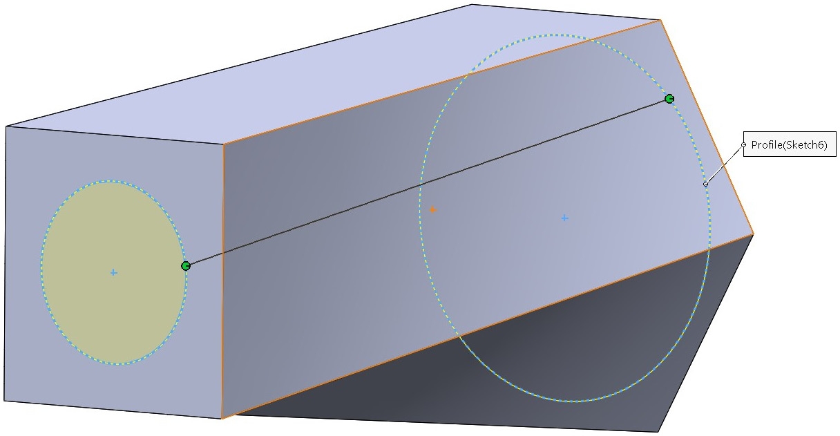
Figure 6.59 – The preview of the lofted cut
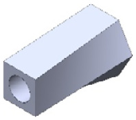
Figure 6.60 – The final 3D model after applying the lofted cut
We can use the cross-section viewing feature at the top of the canvas to view the shape from the inside as well. The result of doing this is shown in the following screenshot:

Figure 6.61 – A cross section of the model showing the cut
- To create a section view, click on the icon shown in the following screenshot. Then, adjust the Section View cross in PropertyManager.

Figure 6.62 – The Section View command on top of the canvas
This concludes our exercise of applying the lofted cut feature. In this section, we covered the following topics:
- How to apply the lofted cut feature
- The effects that the provided guidelines have on circular profiles
- How to make a section view
Now that we know how to apply these two features, we need to know how we can modify them.
Modifying lofted boss and cut
Modifying the lofted boss and lofted cut features follows the same procedure that we follow to modify any other feature. We can right-click on the feature to modify its options. We can also modify the sketches of the profile to adjust the shape of the loft.
Before we conclude this section, let's cover a key aspect of the lofted boss and lofted cut features: guide curves.
Guide curves
Guide curves provide us with much more flexibility when it comes to lofted features that we lack when applying the feature without them. Because of that, we will create the shape shown in the following diagram to learn about one way of using Guide Curves:

Figure 6.63 – The 3D model we are building in this exercise
Let's go through our usual procedure of creating models: planning, sketching, and applying features. Our plan will be to create the two profiles and then create the two guidelines. After that, we will apply the lofted boss feature. Follow these steps to implement this plan:
- Create an extra plane by offsetting the front plane by 50 mm. Then, create the two circle profiles that are shown in the following diagram. The smaller diameter is 40 mm, while the larger one is 60 mm.
Tip
We can hide Front Plane and Plane 1 to make our canvas clearer and less crowded.
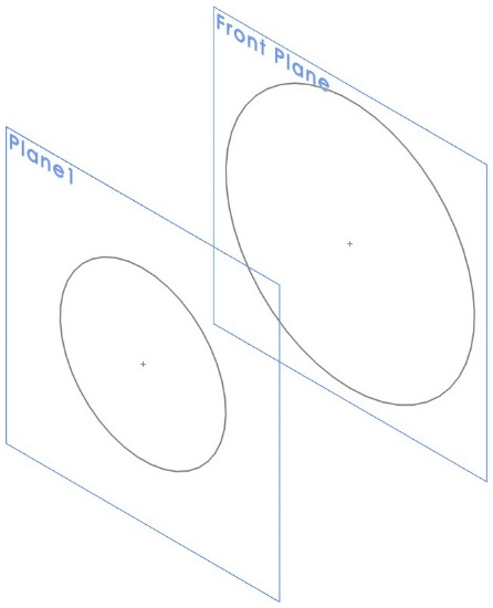
Figure 6.64 – The sketches of the two profiles
- Using the right plane as a sketch plane, sketch the upper guide curve, as shown in the following diagram. Note that to fully define the sketch, the endpoints of the guide curve should have a Pierce Relation with the profile, as highlighted in the following diagram:
Note
The guide curves must intersect with the profiles.
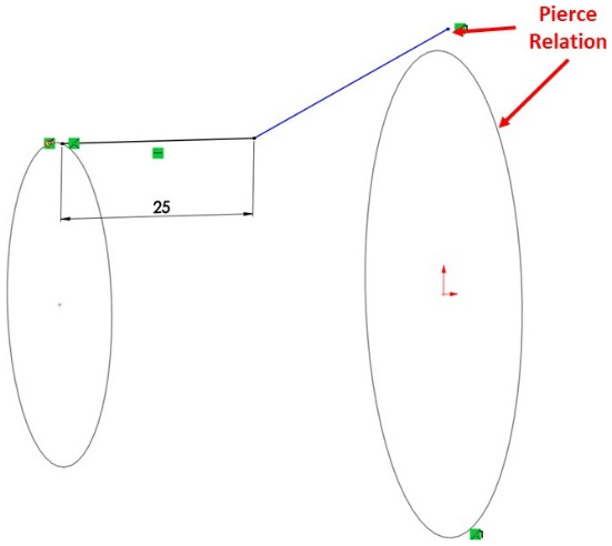
Figure 6.65 – The sketch of the guide curve
- Mirror the first guide curve for the other side, as shown in the following diagram. We are doing this because the lower part of the curve is the same as the top one. Then, exit sketch mode.

Figure 6.66 – The final two guide curves required for the 3D model
- Now, let's apply the lofted boss feature. We will use all of the profiles and the guide sketches to apply it. Select the Lofted Boss command. Then, select the two circular profiles.
- In the Guide Curves section, select the two guide curves we created. Note that we created the two guide curves under one sketch. Hence, when selecting one curve from the canvas, we will see the window that's shown in the following screenshot. As we can see, we can select the Open Loop option and then click on the green checkmark to apply it.

Figure 6.67 – Preview and selection procedure of one guide curve
Note
Our loft will shift toward the guide curve.
- Following the same procedure that we completed in step 5, select the other guide curve. After that, our preview will look as follows:
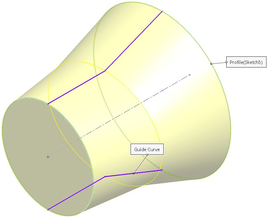
Figure 6.68 – The final preview after both guide curves are applied
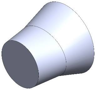
Figure 6.69 – The final resulting shape
Note that we have only applied two guide curves to govern the loft from the upper and lower sides. Hence, from the unguided side, we'll notice that the resulting shape is more elliptical. If we need more guidance when it comes to shape, we can increase the number of guide curves as we see fit. There is no limit to the number of profiles and guide curves we can have.
This concludes this section on lofted guide curves. We covered the following topics in this section:
- How to apply guide curves to control our loft
- How to select a part of a sketch and make it a guide curve
In this section, we covered the lofted boss and lofted cut features, how to apply them, and how to modify them. We also learned about guide curves.
Summary
In this chapter, we learned about a set of features that allow us to create more complex 3D models than what we were able to create in the previous chapters. We learned about plane reference geometries, which allow us to add new reference planes in addition to the default ones. We also covered the swept boss and swept cut and lofted boss and lofted cut features. Each feature set requires more than one sketch if we wish to apply them. For each, we learned their definition, how to apply them, and how to modify them. The features that we covered in this chapter allow us to generate 3D models, such as flexible tubing and irregularly shaped casings.
In the next chapter, we will learn about mass properties, which allow us to assign materials and calculate different properties, such as the mass of our 3D models.
Questions
Answer the following questions to test your knowledge of this chapter:
- What are the eight methods of defining new planes?
- Why do we need to define new planes?
- What are swept boss and swept cut?
- What are lofted boss and lofted cut?
- Create the following model:

Figure 6.70 – The 3D model for question 5
- Create the following model:
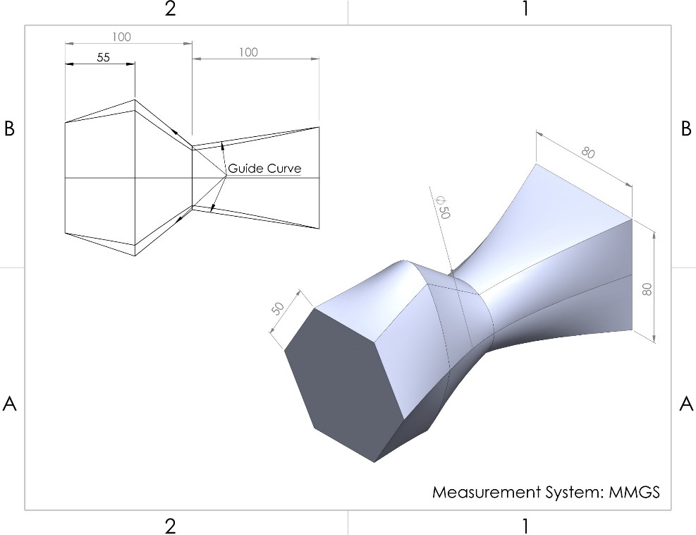
Figure 6.71 – The 3D model for question 6
- Create the following model:

Figure 6.72 – The 3D model for question 7
Important Note
The answers to the preceding questions can be found at the end of this book.