
CONTENTS OF THIS CHAPTER
This chapter covers the following topics:
- the objectives and constraints of systems design;
- systems design in the development lifecycle;
- the scope of design;
- input and output design, technologies and their application;
- the objectives and principles of process design.
OBJECTIVE OF SYSTEMS DESIGN
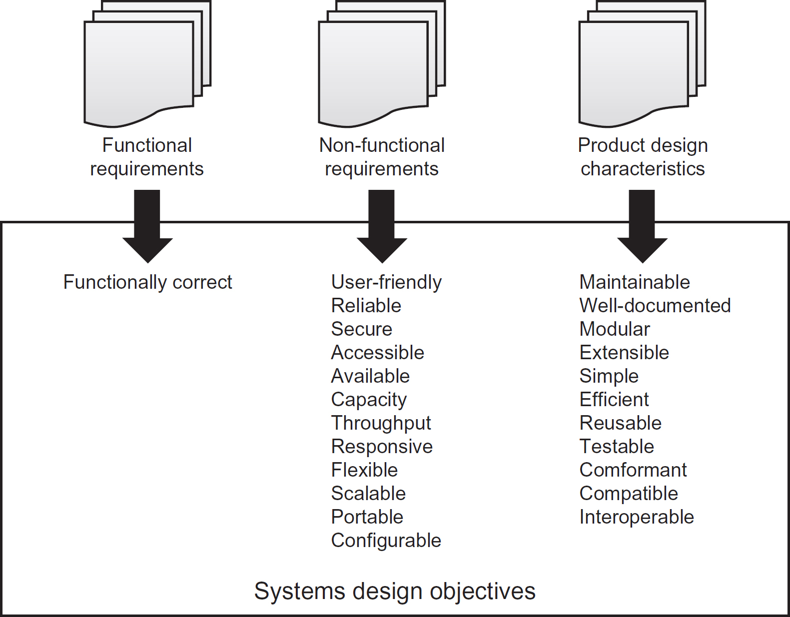
The objective of systems design is to formulate a solution to realise the system requirements. These requirements will typically be categorised as functional or nonfunctional (as explained in Chapter 5). However, there are several additional objectives identified by the manufacturer (in this case, the system developers). Figure 8.1 summarises these objectives.
Functional requirements
Functionally correct
The design provides the functionality specified in functional system requirements, including data maintenance, transactional processes (such as raise invoice, despatch order, renew policy), generation of reports and other outputs.
Non-functional requirements
User-friendly
Delivers the functional requirements in a consistent, intuitive way to support the relative experience of the intended users.
Reliable
Ensures that the system is robust and available at all times when needed. See also available.
Figure 8.1 Objectives of systems design
Secure
Provides adequate controls to restrict access to the system and its data, often for the sake of commercial sensitivity or to satisfy privacy legislation and similar regulations.
Accessible
Ensures that the system is accessible to all potential users regardless of the limitations of disability, their native language or other similar considerations.
Available
Ensures that the system is available when required to fulfil its purpose, often determined by business working hours.
Capacity
Supports transaction and other data volumes as necessary to provide continuous operation into the foreseeable future.
Throughput
Similar to capacity but relates to data/transactional volumes within a specific timeframe, such as the ability to capture 1,000 orders per hour or to support 100,000 simultaneous accesses to a specific internet site.
Responsive
Ensures that the system provides a response to a particular request within a pre-determined timeframe.
Provides the ability to adapt to changing business situations. This is a difficult objective to achieve, and is impossible to guarantee. The objectives of scalability, portability and configurability essentially break this objective down into more specific, testable system features.
Scalable
Provides the ability to up- or down-scale the number of transactions and/or users, to support changing business requirements.
Portable
Provides the ability to ‘port’ the design to different technology platforms and devices.
Configurable
Provides the ability to change the system’s behaviour by setting configuration options or defining system parameters.
Product design characteristics
Maintainable
This objective is essentially covered by the sub-objectives of simple, flexible and well-documented.
Well-documented
Provides documentation to enable the support and maintenance of the system once it passes into operational use.
Modular
This means that the design is based upon the principles of loose (or low) coupling and high cohesion. These concepts will be explored later in this chapter.
Extensible
This is synonymous with flexible.
Simple
The design is not unnecessarily complex. Some developers try to make their programs as complex as they can as a sort of intellectual challenge to other developers, leading to code that is difficult to maintain or error-prone.
Efficient
Makes efficient use of computing resources such as power, processor capacity, memory and storage. This is particularly important for software that will need to be running whilst other software is also sharing the same computing resources.
Re-usable
The design makes use of existing functionality, where available. This may take the form of generic functions, components or web services provided by third-party providers, or even standardised functions, components and services developed in-house.
Testable
Enables system testers to develop test cases and scripts directly from the design deliverables (artefacts), for example, the use of system models such as use cases, class diagrams and state machine diagrams (introduced in Chapter 7) that incorporate business rules and constraints.
The design adheres to standards such as modelling notation and industry-wide, user-interface standards as well as complying with architectural principles and policies, such as modularity and simplicity.
Compatible
Uses a standard data file or message format that can be shared with another system. For example, many independent software products provide the ability to read and/or generate files that can be used by Microsoft Office™ applications.
Interoperable
This literally means the ability to work (operate) with other systems. In practice this may refer to the ability for a system to share data with another system (through the use of a common database, or a data file that is exported by one system and imported into another) or through the consumption of services provided by another system.
In addition to these overarching objectives, individual design activities, such as input design, have their own objectives, which we shall look at in the relevant sections later in this chapter.
CONSTRAINTS UPON SYSTEMS DESIGN
The system designer has a number of constraints placed upon their work. Some common constraints are shown in Figure 8.2.
Figure 8.2 Constraints upon systems design

Project constraints
These represent limitations imposed by project stakeholders and agreed during project initiation.
Money (budget)
It is very rare for a project to proceed without a pre-defined budget. Systems development projects are no exception and this may restrict the scope of features that can be delivered. However, more specifically, the impact may be that the designer has to reduce not just the number of features that the project will deliver, but the way those features are delivered. This may also lead to trade-offs between design objectives. For example, reusability may be a desirable objective, but it is often more costly to build a software component in such a way that it could be reused in other projects.
Timescale
Generally imposes similar restrictions to budget as the two are intricately linked.
Skills/resources
Projects rarely have unlimited resources at their disposal, generally as a consequence of a fixed budget. Although resources are broader than just people, it is the people restrictions that have the most impact on the design stage of development, in terms of a lack of skills in a particular technology. A lack of access to the latest technology (in terms of hardware and software) may also be a constraining factor. These factors often steer the design of a system down the tried and tested path that an organisation is familiar with rather than attempting to break new ground.
Technical constraints
Similarly to project constraints, technical constraints are often identified during project initiation. However, unlike the project constraints, they tend to relate to more strategic issues often defined within enterprise-wide architectural policies, standards and principles that govern a range of or all projects.
Hardware and software
We have already touched on this, but organisational standards may also dictate that only certain hardware or software may be used. This is especially true of organisations that have introduced enterprise architecture teams to define and govern the use of IT.
Legacy systems
If the system under development needs to interface to legacy systems (those perhaps built using old technologies that the organisation no longer uses for new systems development), then the system may need to use specific protocols that are perhaps no longer supported, or specific file formats that are no longer used for new developments. This may require proprietary development languages to develop interfaces with the legacy systems. One way to deal with these situations is to build a layer of software called a ‘wrapper’ that acts as an adapter, translating between old and new formats and protocols.
Programming language
Organisations often have enterprise-wide standards regarding the programming languages and development tools to be used during systems development. This may constrain the designer as not all languages provide the same features. Furthermore, the more traditional languages, such as COBOL, do not provide support for object-oriented design – discussed later.
Standards
Typical industry-wide technical standards that must be complied with when designing a new computer system include:
- User-interface style guides – such as those defined by Apple.
- Data formats – such as the use of open standards like XML.
- Protocols – such as SOAP (Simple Object Access Protocol) and REST (Representational State Transfer), used for passing messages in a service-oriented architecture.
- Security – such as ISO 27001 (the international standard describing best practice for an Information Security Management System), ISO/IEC 7498 (Open Systems Interconnect (OSI) security model), ISO/IEC 13335 (IT security management), ISO/IEC 27005 (Information technology – Security techniques – Information security risk management).
- Application specific standards – such as PCI DSS (Payment Card Industry Data Security Standard).
- Modelling standards – such as the use of the Unified Modeling Language (UML) notation when producing design models.
Organisational constraints
The development organisation, or even the customer organisation if the developers are a third-party provider, often imposes constraints that must be adhered to by the designer. Some of these have been covered under technical standards, but other constraints include:
Politics
Sometimes, for seemingly unfathomable reasons, an organisation chooses to follow an inappropriate project approach or to use an unsuitable technology or software tool. This may be as a consequence of a new CIO (Chief Information Officer) or IT Manager wishing to make their mark or introduce technology, standards or processes that they are more familiar with, even though they may not be suitable within their new organisation.
Stakeholders
There are typically three key issues relating to stakeholders that constrain the designers ability to complete their work:
- Availability – perhaps the greatest constraining factor regarding stakeholders is their availability for providing clarification regarding their requirements. Even accepting that the requirements provided to the designer are of good quality, they often change during the development process;
- Authority – sometimes the ability to obtain authorisation for changes is restricted due to the stakeholders requesting them having insufficient authority;
- Sign-off – the ability of stakeholders to approve and sign-off the design before software construction commences is highly-questionable in many system development projects, mainly down to the use of esoteric notations and models during the design process. Consequently, design specifications are rarely approved and signed off by business stakeholders.
Standards
Every organisation tends to define its own standards, in addition to industry-wide standards adopted for achieving ‘best practice’. Some typical examples of organisation specific standards include:
- User-interface style guides – prescribing consistent use of fonts and corporate colours, positioning of logos, use of standard terminology, for example;
- Reporting standards – similar to user-interface guidelines, but governing the look and feel, layout, sorting, filtering and totalling on reports generated by computer systems;
- Module design guidelines – some organisations define standards that must be met during process design regarding the coupling, cohesion and simplicity of system processes/modules/components. These standards also form the basis for static testing of programs once written.
Legislation
The most prevalent legislation affecting computer systems is data protection legislation, for example the UK Data Protection Act 1998 (DPA). However, each sector has its own legislation to contend with, which typically places restrictions on the designer, who needs to ensure compliance within the solution.
Often, systems need to work in different environments, in different countries, which have different ways of working and different languages or currencies. This may restrict the way a solution is designed or may require a particular approach that conflicts with design objectives such as simplicity and maintainability.
Quality of requirements
Perhaps the factor most commonly attributed to the failure (or success) of a systems development project, is the quality of requirements. Requirements engineering (the subject of Chapter 5) strives to produce high-quality requirements, but unfortunately it is still commonplace to see requirements that do not meet such stringent quality criteria. This leaves some system features open to interpretation, which, ultimately, requires more of the designer’s time through seeking clarification, or worse, having to re-work the design later in the Systems Development Lifecycle (SDLC).
SYSTEMS DESIGN IN THE DEVELOPMENT LIFECYCLE
Systems design is a critical stage within systems development, but the extent of the design and approach taken varies considerably depending on the approach to development taken. For example, with defined approaches to development, the emphasis is on producing a complete design up-front (often referred to as ‘big design up front’) that comprehensively supports (realises) the entire set of requirements. Alternatively, with Agile approaches, the emphasis is on a ‘divide and conquer’ approach, whereby an agreed subset of system features is explored and built within a short development lifecycle, that repeats (iterates) a number of times until a complete set of functionality has been delivered.
Chapter 2 considered four fundamental systems development lifecycle (SDLC) models that provide the framework for systems development:
- Waterfall
- ‘V’ model
- Incremental
- Iterative
Within the first three, there is a dedicated stage or stages for design, whereas the Iterative model does not have a dedicated design stage.
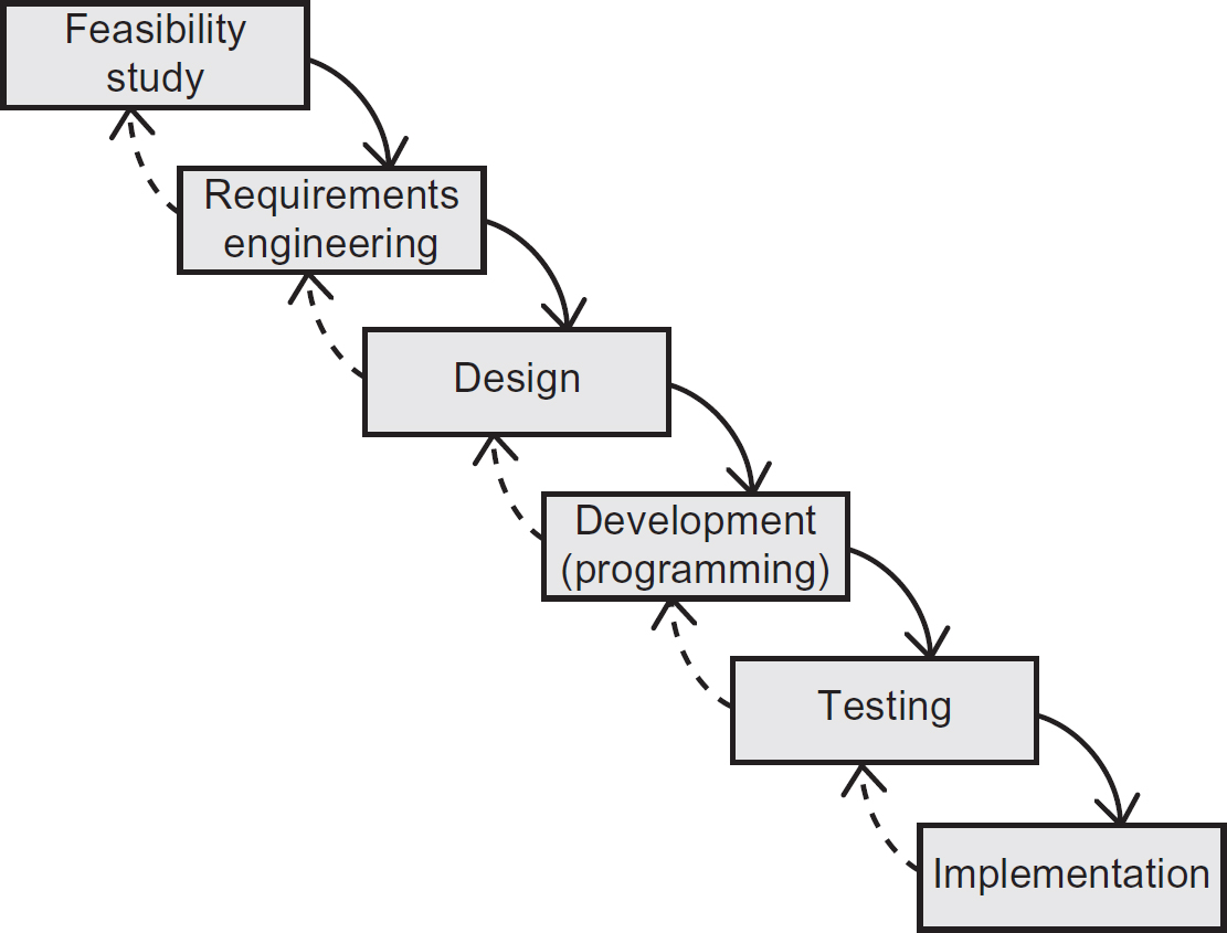
Waterfall
The position of design in the Waterfall lifecycle (Figure 8.3) is clearly defined and follows requirements engineering. Consequently, design commences only after a definitive set of requirements have been validated and signed-off by the project sponsor.
This approach has advantages and disadvantages. First, it means that a comprehensive design can be undertaken in one stage, providing a robust set of blueprints as a basis for programming. However, if any of the requirements change after design approval, this necessitates that the design be re-evaluated, modified and re-validated.
Figure 8.3 The place of design in the Waterfall SDLC
‘V’ model
The ‘V’ model is very similar when it comes to the approach to systems design. However, as a consequence of aligning the stages of specification to explicit test stages later in the lifecycle, design is split into high-level system design and individual unit or component design (also referred to as module design), as shown in Figure 8.4.
Figure 8.4 The place of design in the ‘V’ model SDLC

The high-level system design stage identifies (but does not define in detail) the components (modules or units) required to realise the requirements and the required interfaces between them. The unit/component design stage provides a detailed specification for each component identified in the high-level design to enable a systems developer to write the code. This is also referred to as a program specification.
The ‘V’ model, in addition to showing the discrete stages of design, also shows explicitly the outputs from the design stages (interface and program specifications) that drive the corresponding integration and unit testing stages.
Incremental
Similarly to the ‘V’ model, the Incremental model (Figure 8.5) effectively splits design into both high-level and module design. The high-level design is performed ‘up-front’ to ensure a coherent solution that fits together robustly but the module design is deferred to the individual incremental development stages, where a subset of features is designed in detail, built, tested and deployed (implemented).
Figure 8.5 The place of design in the Incremental SDLC

Iterative
Design is an explicit step in the original Spiral lifecycle model (the original basis for modern iterative lifecycles) that takes place after an operational prototype is produced in the final iteration. More recent interpretations of the Iterative lifecycle do not explicitly show design as a stage or step, however, that is not to say that approaches based on the Iterative lifecycle do not recognise design as a key activity within systems development.
Figure 8.6 shows a typical Iterative SDLC used as a foundation for Agile systems development (introduced in Chapters 2 and 6). Agile approaches focus on developing and delivering working software without reliance on formal specifications produced early in the lifecycle. Key design decisions are still made, but they are reflected in the development of evolutionary prototypes rather than documented as a specification for developers to use. It is only at the end of an Iterative development cycle when a production-ready version is completed that the key design decisions are documented, to provide an important reference for ongoing support and maintenance. Consequently, the overall system design evolves throughout a series of Iterative development cycles, where each cycle explores and builds a new set of system features.
Figure 8.6 The place of design in an Iterative SDLC

THE SCOPE OF DESIGN
Although each systems development project is different, a good place to start considering the scope of design is to identify the key elements of a computer system, as shown in Figure 8.7, which has been reproduced by permission of Assist Knowledge Development Ltd.
Figure 8.7 Key elements of a computer system

Figure 8.7 identifies four key elements: inputs, outputs, processes and data. However, it also includes system controls, such as verification, validation, security and encryption. Hence, the key activities of the designer’s work can be summarised as:
- input and output design (often referred to as I/O design or external design);
- process design;
- data design;
- security and control design.
These design activities are typically driven by the products (or deliverables) of the analysis stage that precedes systems design, depending upon which SDLC approach is taken. These products of analysis generally include a requirements document (containing functional, non-functional, general and technical requirements) and supporting documents, including models of the functional and data requirements, such as a UML use case diagram with supporting use case descriptions (functional) and an analysis class diagram (data).
The next four subsections explore each of these activities in more detail.
Input and output design
Input requirements are defined during requirements engineering and specified in either a requirements catalogue, a functional specification, or both. Therefore, the start point for I/O design is the requirements catalogue and some form of functional specification, the latter generally comprising a function model with supporting descriptions. A de-facto standard these days is a use case diagram and associated use case descriptions (from UML); however, a data flow diagram (DFD) and associated elementary process descriptions are also commonly used. The functional specification and requirements catalogue are often supplemented by prototypes of example screens and reports.
Figure 8.8 shows an example of a use case diagram for a sales order processing system. The inputs and outputs requiring design are clearly identified from the points where associations between actors and use cases cross the system boundary. Hence, we can identify the following potential inputs and outputs:
- order details;
- picking details;
- despatch details;
- delivery details;
- invoice details.
Figure 8.8 Use case diagram for a sales order processing system
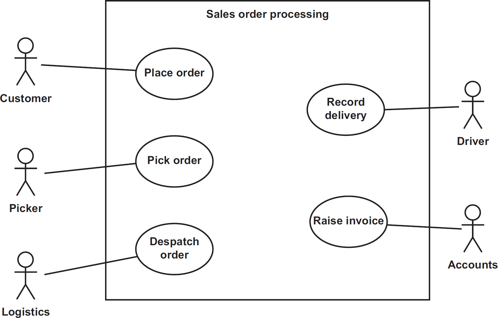
It is not possible to determine from the diagram alone whether each of these associations are actually inputs, outputs or two-way dialogues. This is where the supporting use case descriptions come in, to clarify the nature and content of the interaction between the user (the actor on the use case diagram) and the system being designed.
I/O design has two distinct areas that we refer to as macro design and micro design. At the macro level, the designer considers the overall mechanism for achieving the inputs and outputs, including the use of appropriate technologies. At the micro level, the designer focuses on the detailed design of the user interface, including content and layout of forms, reports and interface files.
User interface design
To the end user, the user-interface (UI) is the system. They do not have visibility of the internal workings of the system; the way it stores and manipulates its data. Consequently, the design of the UI is arguably the most critical part of the work of the designer, except for batch processing systems, where the UI is minimal.
The purpose of the UI is to make the computer system usable by the end user, a quality often referred to as ‘user-friendly’. Hence, the most critical aspect of a UI is its usability – adapting a computer system to the humans who use it. If a UI is difficult to learn or confusing/tedious to use, then the system will become an obstruction to the user rather than a helpful tool. In the case of web-based systems, this may even result in a customer deciding to visit a competitor’s site to make their purchase!
Usability is subjective and can only be determined (and measured) with specific reference to the type of user, the task they are performing and the environment within which they are using the system. Some of these considerations will have been captured within explicit usability requirements during requirements engineering.
What constitutes ‘user-friendly’ is sometimes difficult to quantify, which is why designers often use prototypes (storyboards and wireframes), checklists and style guides to assist them when undertaking detailed UI design. A usability checklist includes:
- consistency (consistent look and feel, use of terminology, and so on);
- following the logical workflow;
- logical tab sequence;
- meaningful field descriptions and formats (for example, ‘Enter order date (dd/mm/yyyy)’);
- identification of mandatory values;
- default values;
- confirmation messages;
- clear error messages;
- progress indicators;
- facilities to undo/back out;
- context-sensitive help;
- alternative data entry mechanisms (such as keyboard shortcuts);
- limited entry options (such as drop-down lists and tick boxes);
- use of jargon-free language;
- simplicity (uncluttered screens, reports with only relevant information, and so on).
User considerations
In addition to specific considerations for users with disabilities, the designer should also consider each user’s level of IT expertise. An infrequent or inexperienced user may need a UI that guides them through a process step by step, whereas an experienced, frequent user may need shortcuts to enable them to achieve a task quickly.
With the advent of the internet, more uses of computers are via websites, where it is impossible for the developers to provide training to the users in the same way that they would with office-based systems. Hence, the challenge is to make the UI intuitive, whereby the user requires little or no guidance in terms of how to use it, and what guidance is provided is usually in the form of tool-tips or context-sensitive help to access a help-screen that provides explanation about the screen that they are currently using, or the feature that they have selected.
Input design
The principal objective of input design is to specify how the system will collect data in its raw form (for example a paper-based form or a third-party system’s database) and convert that data into an internal format (all computers use a binary code internally, which uses only the two binary digits 0 and 1) that the system can understand. In addition to ensuring that the functional requirements are met, the designer must also take into account a number of other considerations:
- Efficiency – to ensure that the input mechanism makes efficient use of resources, such as mains power, processor and memory usage.
- Reliability – to ensure that the input mechanism is available whenever it is needed.
- Timing – to minimise any delay during the data collection and translation process.
- Accuracy – to minimise the introduction of errors in the captured data.
- Usability – to ensure that the approach taken is easy for the user to perform and supports their level of ability.
- Cost – the cost should not outweigh the benefits derived from using a particular approach/mechanism.
To understand the decisions that the designer makes during input design, it is necessary to understand how the input process works. Figure 8.9, which has been reproduced by permission of Assist Knowledge Development Ltd, shows the various stages involved.
Figure 8.9 Stages during data input
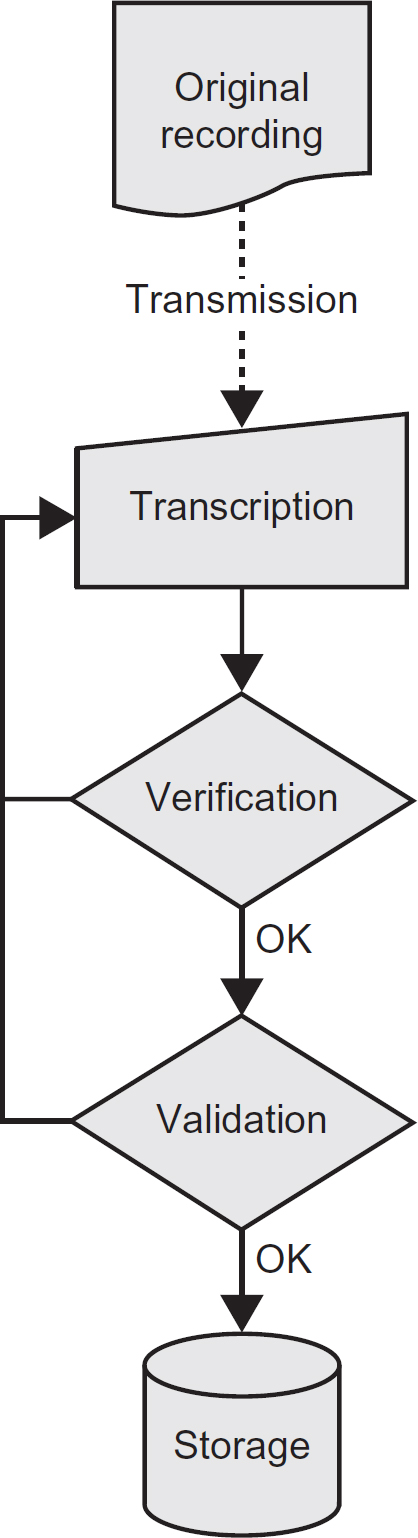
Original recording
Data is created or captured at its source. In the early days of computerisation this was achieved using a hand-written data capture form, although modern computer systems may capture data using a number of different mechanisms, as explored later in this chapter.
Transmission
The captured data is sent to some location, where it is converted into an internal format understandable by the system. Modern computer systems tend to achieve the transmission electronically.
Transcription
The captured data is converted (transcribed) into the internal format used by the computer system. Historically this would have been achieved by a data entry operator ‘keying’ the data using a keyboard, but, again, modern systems have a number of options available, discussed later.
Verification
Whilst the data transcription process is being performed, the transcribed data is checked to ensure that no errors are introduced, most commonly, that the data entry operator has mis-keyed some of the data. Such errors are referred to as transcription errors. Being a form of system control, verification is considered later in the section on controls and security.
Validation
The transcribed data is subjected to further checks to ensure that it complies with pre-defined data integrity principles and business rules defined by the business stakeholders. Again, validation is considered under the section on controls and security later.
Storage
The final stage is to store the data in a permanent or semipermanent storage system for future use.
The designer needs to make decisions covering the above stages to ensure that the approach taken meets the objectives identified above, most notably to minimise delay and cost whilst maximising accuracy and usability. These guidelines should be borne in mind when deciding how to achieve these objectives:
- Minimise the amount of data recorded. The more data to be captured, the greater the effort required (cost and time) to collect, transmit and transcribe the data, and the higher the likelihood of error.
- Minimise data transmission. Each transmission of data incurs cost, has the potential to delay the input process and increases the chance of errors being introduced.
- Minimise data transcription. Transcribing data from one form into another increases the chance of error and incurs cost and delay.
- Verify and validate to ensure accuracy. Choose appropriate checks based upon the nature of the data involved and the data capture environment. This is discussed further later in the chapter.
- Choose appropriate input technologies. The chosen technology should support the needs of the intended user whilst being appropriate to the application (timing requirements, data volumes and so on) and target data capture environment, whilst providing value for money.
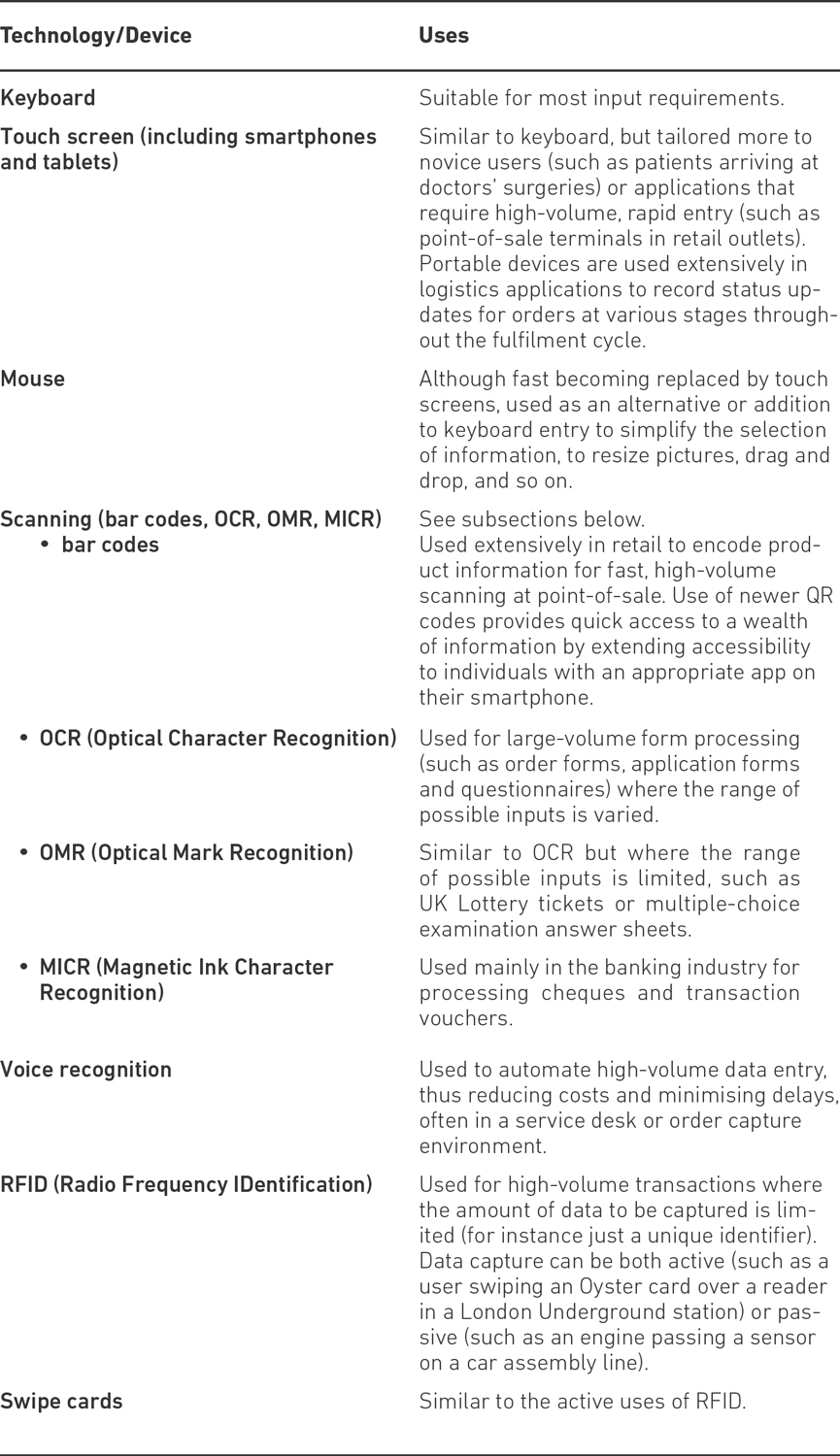
As the last point suggests, designers must be familiar with a wide range of technologies so as to select those appropriate to support the system requirements. Different technologies score differently in terms of the considerations we identified earlier (efficiency, reliability, timeliness, accuracy, usability and cost). Table 8.1 provides a list of the most common technologies and typical uses, but a detailed explanation of these technologies is outside the scope of this book.
Input devices can be classified as direct or indirect. Indirect input devices require a human user to interpret the source data and translate it into key presses or some other form of interaction with the system. Direct input devices enable capture and transcription into a computer-readable format without the need for a human user to undertake any translation, thus eliminating transcription errors almost completely.
A further consideration during input design is whether the input must be undertaken in real time (often referred to as ‘online’) or whether it can be batched up and processed at a later time (for instance, overnight). Key factors in deciding whether a batch input approach may be more practical are the volumes of data being captured/processed, the timing constraints of the application and the costs involved. Online data input is more desirable from a business perspective but it is sometimes difficult to justify the costs involved and hence batch input becomes a more practical solution.
Table 8.1 Common input technologies
The detailed design of input interfaces depends upon the mechanism and technology the designer has selected to achieve a particular input. Consideration of all options is outside the scope of this book, but we consider here the most common options available to the designer when designing interfaces for use with standard desktop computers and laptops.
User interfaces are often referred to as ‘dialogues’, which can cover both input and output. UML use cases provide a useful start point for designing a dialogue because they define the required flow of input and output responses needed. The structure of the dialogue will control the interaction between the user and computer and determine how information is presented and received. Dialogues vary in this degree of control from user-initiated (where the user is in command) to computer-initiated (where the user simply responds to the requests of the system).
To be effective, a dialogue has to be functional and usable. Functionality is concerned with ensuring that all the required data has a mechanism for input and output. Usability means that the users of the system should be given a dialogue that is ‘user-friendly’, as described above.
The most common types of dialogue structure used in modern computer systems are explained below:
Menus
Menus present a selection of the possible options for users to select from, typically by clicking on the option using a mouse or similar device. A distinction can be made between a dropdown menu, where the menu option appears in the menu bar of the application window and a pop-up menu, that appears when specifically invoked by the user, typically by right-clicking a specific element on the screen. The items displayed on a pop-up menu depend on where the pointer was located when the button was pressed. Menus may also have sub-menus (cascading menus).
Form filling
Input data is entered onto screens that resemble a form. Areas of the screen are protected from input and the cursor is placed at relevant points to indicate where and in what order the data is to be entered.
Command language
With menus and form-filling, the dialogue is initiated by the system. However, command language dialogues are user-initiated. The system waits for an instruction and the user initiates the dialogue by entering pre-defined commands or codes, known to the system, and the system then responds accordingly.
Question and answer
The system guides the user through the dialogue in the form of a series of questions to respond to. A variant of the Q and A dialogue was originally called a ‘wizard’ and this style of dialogue is now combined with form-filling on modern web-based systems.
Selection of appropriate dialogues depends on a number of factors, not least the experience of the target user.
Output design
The principal objective of output design is to define how data that is stored and/or manipulated by the system will be extracted and presented in a format that can be interpreted and used to meet certain functional requirements that would have been defined during requirements engineering. The recipient of outputs is either the system end user or another system. In addition to ensuring that the functional requirements are met, the designer must also take into account a number of other considerations, many of which are also common to input design:
- Efficiency – to ensure that the output makes efficient use of resources, such as mains power, processor and memory usage and consumables like paper and toner/ink.
- Reliability and timing – to ensure that the outputs are available when they are needed.
- Accuracy – to ensure that any data output from the system is correct and up to date.
- Usability – to ensure that the outputs are easy for the user to obtain and interpret.
- Clarity – (arguably a subset of usability) to ensure that the format and content of the output can be clearly understood by its intended recipient, ideally without separate instructions to clarify.
- Relevance – to ensure that the output provides only the data that is required to fulfil its purpose. Any data beyond this will detract from its purpose and compromise its effectiveness.
- Quality – the required quality of the output will often be determined by whether the output is intended for personal or public use, for internal use or distribution to external stakeholders, such as customers. There may also be regulatory or legal requirements governing the precise specification of certain outputs.
- Cost – the cost of generating the output in the chosen format and using the selected technology should not outweigh the benefits derived from the use of the output.
One of the key decisions that a designer must make when undertaking output design is the choice of technology to use and different technologies score differently in terms of the above considerations. Table 8.2 provides a summary of the most common output technologies and their potential uses.
Table 8.2 Common output technologies
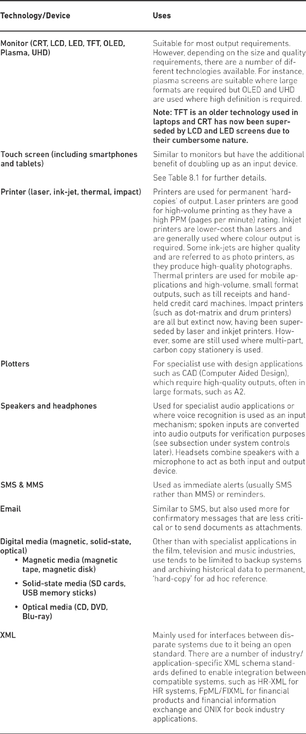
When choosing appropriate output technologies, the designer must pay particular attention to the following:
- The application itself. For example, the production of payslips for a payroll bureau will impose quality, volumetric and timing constraints necessitating the deployment of high-quality printer technology. A simple, screen-based enquiry showing the status of an order to assist a despatch clerk with the scheduling of deliveries may only require a basic monitor, whereas the scoreboard at a major sporting stadium will require large-scale plasma technology to enable spectators to read from a significant distance.
- Circumstances. User and environmental constraints also influence the selection of the output device. Sight-impaired people will require special consideration and audio or touch devices may be needed. The location of the information requirement may demand output devices that have certain security features, are tolerant to dirt and dust or which are mobile and can be handheld.
- Cost. Budgets are usually a constraint on system development projects, so the designer must be careful to select technologies that are justified and deliver benefits that outweigh their cost. Whilst business stakeholders may want to use the latest, state-of-the-art devices, their cost is often difficult to justify, as they may not deliver any additional benefits over and above more established, cheaper devices.
Output user-interfaces
The most common output interfaces are screen-based enquiries (including graphical dashboards), printed reports and documents (such as invoices or payslips), although reports and documents are increasingly being generated in electronic form, such as Adobe’s Portable Document Format (PDF). Often the precise content, and even the layout, will be pre-defined within the system requirements documentation, frequently as prototypes. Sometimes the content and format may even be determined by legislation, such as key documents produced by payroll systems.
When considering reporting requirements, the designer needs to consider the most appropriate format to use, unless this has already been pre-empted in the requirements. The most common options are:
On demand
These are usually produced to satisfy ad hoc queries about data stored in the system. Ad hoc reports are often executed on extracted data that perhaps reflect figures as at a point in time, such as end of previous day.
Summary
These only provide totals from a set of more detailed data records. Often produced at specific intervals such as end of day, month end, end of financial year. Again, most summary reports are produced from extracted data.
Exception
These reports highlight exceptional or extraordinary situations to prompt investigation or action. For example, a list of orders that have not been fulfilled at the end of the day, to prompt immediate action to deal with them as a priority at the start of the next day.
Data dumps
Often data is output as a file for use by a software-based reporting or analysis tool (such as a spreadsheet), for subsequent manipulation and analysis.
Archive
Some reports are produced when the appropriate data is no longer required on the system. For example the details of a dead person’s medical records may be output on paper or microfiche1 for research purposes. Similarly, reports of historical financial transactions may be required for company taxation purposes.
Increasingly, organisations are looking for flexible reporting options, as it is not cost-effective to continually produce ‘built-in’ reports within their systems as new information requirements are identified. Consequently, a popular option available to the designer might be to recommend a dedicated reporting tool that can be used by business stakeholders to create their own reports as and when the need arises. These reporting tools often access data stored in a data warehouse, which contains extracted data from operational systems that are optimised for flexible, read-only analysis and reporting, often referred to as OLAP (OnLine Analytical Processing). The use of dedicated reporting databases (data warehouses) ensures that the use of reporting and OLAP tools does not affect the performance of the ‘live’ operational systems.
System to system data interchange
So far, we have considered I/O design in the context of communications between humans and computers. However, as more and more source data is being shared between systems, the I/O design task often needs to consider how the data will be extracted from a source system and be transmitted to a destination system, and then converted into a form that can be used by the system.
The functional model for the new system (such as the use case diagram in Figure 8.8) should identify the system boundary and define any interfaces with other systems. The ability for systems to interface with each other is referred to as interoperability and, traditionally, systems exchanged data using a mechanism known as EDI (Electronic Data Interchange). However, more recent developments use standard protocols to effect a point-to-point exchange of data using XML data files and schemas, often with the aid of a specialist piece of software referred to as middleware.
PROCESS DESIGN
The principal objective of process design is to specify how the functional requirements defined during requirements engineering will be realised using a series of individual programs or software components that will be built and will interact with each other in order to deliver the required system behaviour. Process design is often sub-divided into two discrete activities:
- High-level system design. This is concerned with identifying the discrete components needed to realise the functional requirements, and the interfaces necessary to enable them to communicate with each other.
- Detailed program specification. This defines how each component identified in the high-level design is to be internally built. This activity corresponds to the unit/component design stage in the ‘V’ model lifecycle in Figure 8.4 and is also referred to as module design or component engineering.
Furthermore, the objectives identified earlier come into play here, such as the need to produce reusable code and the desire for an efficient, reliable, expandable, maintainable solution.
As with I/O design, the start point for process design is the requirements catalogue and some form of functional specification. If we take the UML use case model in Figure 8.8, then this would identify five key system processes to be specified, one for each use case:
- Place order;
- Pick order;
- Despatch order;
- Record delivery;
- Raise invoice.
The approach that the designer takes from here depends on the target environment that the new system will be deployed in. For instance, if the system is for a stand-alone PC with a single user, then the design can be relatively straightforward, but if the target environment is a series of networked workstations that are geographically dispersed, with mobile users requiring access from their laptops, smartphones and tablet devices, then the task becomes significantly more complex.
High-level system design
If we consider a very simple environment like a stand-alone, single-user PC, then the high-level design may determine that the system can be developed as a single executable component. Hence, the design may focus on a set of sub-modules (often referred to as sub-routines or functions) that are linked together to form a single executable program, as shown in the form of a simple module chart in Figure 8.10.
Figure 8.10 Simple module chart for a stand-alone system
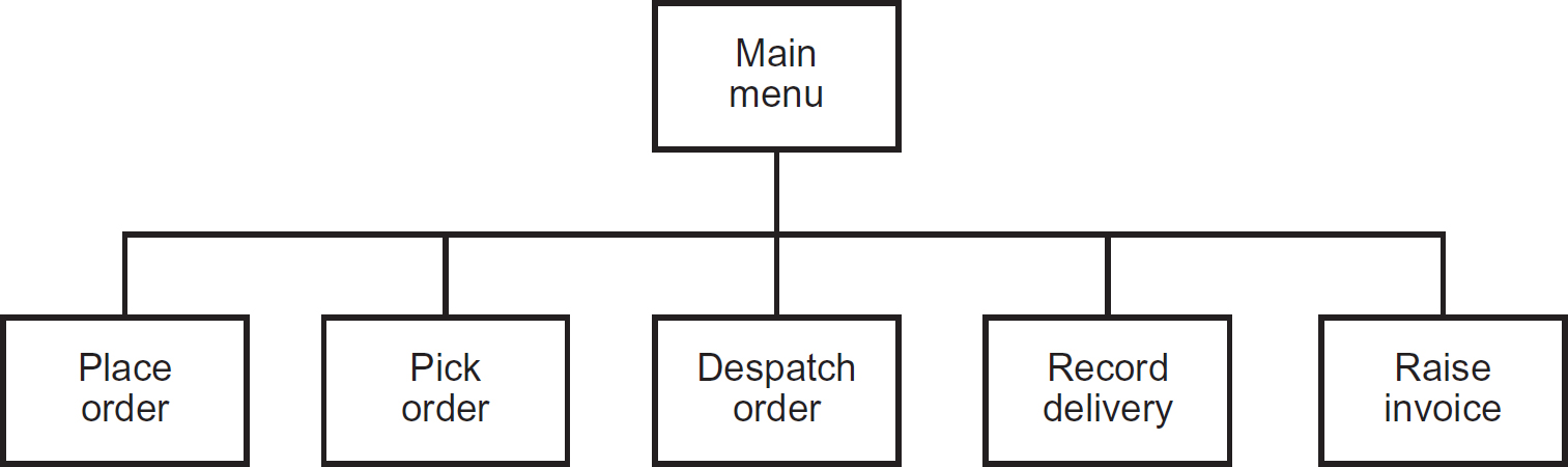
Having identified each of the high-level program modules, the designer would continue to specify each in more detail, using a technique known as stepwise refinement, which we shall consider later.
In contrast, we shall consider an example where the designer has identified a need to divide the functionality into a set of stand-alone components that can be deployed separately (for instance, on different servers within a local-area network), and where some common functionality is shared between components, as shown in the UML component diagram in Figure 8.11.
Figure 8.11 High-level design showing separate components and their interfaces
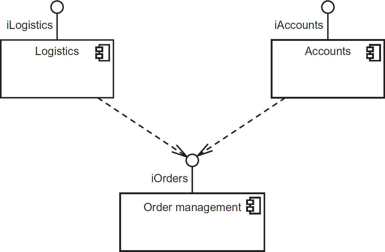
In Figure 8.11, we can see three separate components (Logistics, Accounts and Order Management), each providing a set of services defined in an interface (shown by the ball joint). Hence, iLogistics is the interface provided by the Logistics component, iAccounts is the interface provided by the Accounts component and iOrders is the interface provided by the OrderManagement component. Figure 8.11 also shows that the Logistics and Accounts components both have a dependency on the iOrders interface provided by the OrderManagement component, denoted by the dashed arrows.
Figure 8.11 does not include any indication of the technologies that will be used to build and deploy the components; it just shows, logically, which components will be needed and the required interfaces between them.
Figure 8.12 shows a UML class diagram that is being used to define the iOrders interface in more detail, by explicitly showing which services the interface will provide.
Figure 8.12 UML class diagram showing a detailed definition of an interface
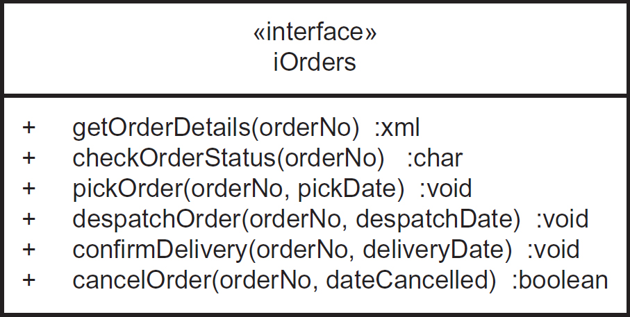
As can be seen from Figure 8.12, iOrders provides six services that can be invoked by the Logistics and Accounts components:
- getOrderDetaiis;
- checkOrderStatus;
- pickOrder;
- despatchOrder;
- confirmDelivery;
- cancelOrder.
Notice also that each service takes parameters that pass information (such as the order number in question and the pick/despatch/delivery/cancellation date) from the Logistics and Accounts components to the OrderManagement component, and returns information back to the component that invokes the service in the form of return values (such as an XML message containing the order details), returned by the getOrderDetails service or a boolean (true/false) value indicating whether the order has been successfully cancelled, returned by the cancelOrder service.
Stepwise refinement
From a high-level view of the design, such as the module chart in Figure 8.10, the designer gradually breaks down each module into more detail, elaborating the requirements into a form detailed enough to enable a developer to produce a solution. This process is referred to as stepwise refinement. There are two common approaches:
- Top-down. An overview of the system is first formulated, specifying but not detailing any first-level sub-processes or sub-systems. Each sub-process/sub-system is then refined in yet greater detail, sometimes in many additional levels, until the entire specification is reduced to base elements.
- Bottom-up. The individual base elements of the system are first specified in great detail and these elements are then linked together to form larger subsystems, which in turn are then linked, sometimes in many levels, until a complete top-level system is formed.
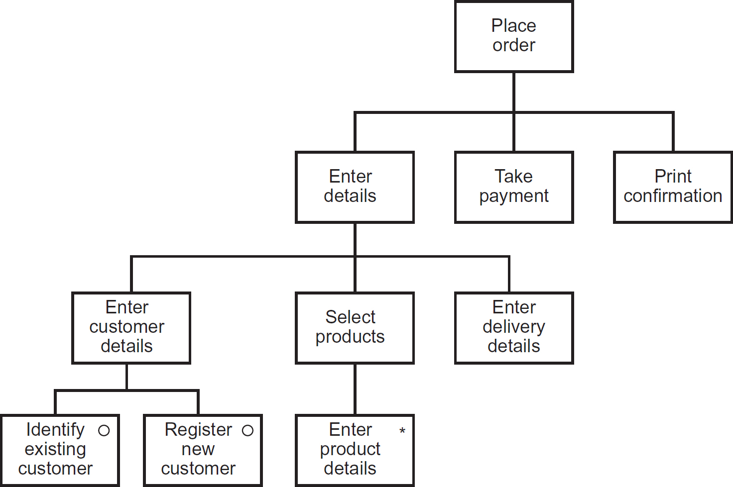
Figure 8.13 provides a de-composed view of the Place Order module from Figure 8.10 using a notation called a structure chart, as used with the Jackson Structured Programming (JSP) methodology.
In the example in Figure 8.13, the high-level module Place Order from the module chart in Figure 8.10 becomes the top-level driving module, which is then decomposed into three further modules: Enter Details, Take Payment and Print Confirmation. The Enter Details module is then de-composed into three further, more cohesive modules (the concepts of coupling and cohesion in process design are discussed later): Enter Customer Details, Select Products and Enter Delivery Details, and so on. The modules Take Payment, Print Confirmation, Enter Delivery Details, Identify Existing Customer, Register New Customer and Enter Product Details are at a base level, where further de-composition within the same diagram would render the diagram unusable. These base level modules are best de-composed using a simple flow chart (such as a UML activity diagram) or a textual notation such as Structured English (also referred to as pseudocode). The module/structure charts, as the name implies, define the structural elements of the system processing, whilst the flow charts and pseudocode define the detailed behaviour of the modules.
Figure 8.13 Structure chart showing the de-composition of the Place Order module
Programming constructs
The JSP structure chart in Figure 8.13, as well as showing the de-composition of the high-level module Place Order also explicitly identifies the three fundamental constructs supported by all programming languages: sequence, selection and iteration.
- Sequence. Steps in a process (or program source code statements) are executed in sequence. The sequence never changes and all steps are executed every time the process runs. In Figure 8.13 the modules Enter Details, Take Payment and Print Confirmation form a sequence construct, as do Enter Customer Details, Select Products and Enter Delivery Details.
- Selection. Steps in a process are selectively executed dependent on certain conditions. In Figure 8.13 the modules Identify Existing Customer and Register New Customer form a selection construct, as only one of those modules will be executed (not both) dependent on some condition, which would be evaluated in the module Enter Customer Details. In JSP, a selection is denoted by using the symbol ° inside the module box.
- Iteration. Steps in a process are executed a number of times, dependent on some condition. In Figure 8.13 the module Enter Product Details is an example of an iteration, as it would be repeated for each product being ordered. In JSP a selection is denoted by using the symbol ° inside the module box.
When identifying and defining the high-level modules of a system the designer must take into account the principles of good modular design, such as reusability and maintainability. Both of these principles are addressed by two design concepts: coupling and cohesion; these place constraints upon the modules by requiring them to be loosely coupled and cohesive.
Coupling is effectively a measure of the independence of the modules. Loosely coupled modules are relatively independent of one another, so that one module can be modified with little or no impact on the other. However, there must always be coupling, and hence, dependency, between two modules if one uses the services provided by the other, as in the example in Figure 8.11. We have already considered the concept of an interface (as shown in Figures 8.11 and 8.12), which is the mechanism designers use to achieve loose coupling.
Cohesion is a measure of how closely related all the aspects of a module are to each other. A module should have a well-defined role within the system and carry out a single, problem-related function. Hence, the designer breaks down a module that is not cohesive (in other words, covers more than one function), into a set of more ‘single-minded’ sub-modules, as shown in Figure 8.13, until all of the lowest level modules perform only one, well-defined function.
In general, loosely-coupled, cohesive modules can be more easily reused, as is the case of the Take Payment module in Figure 8.13, which could potentially be used in a number of systems. Furthermore, the designer may decide to use a ready-made component that provides payment functionality, or even a web service such as PayPalTM.
Unit/component design
The high-level design effectively treats the modules as ‘black-boxes’, where the internal workings are not visible but only the observable behaviour and any interfaces are determined. Once the high-level modular design is complete, the designer can turn their attention to specifying the detailed workings of each module. These specifications are often referred to as program specifications, as they effectively specify the work that the programmer needs to undertake. The most commonly used techniques for specifying these program units are flow charts (such as the UML activity diagram) and pseudocode (also called Structured English).
Figure 8.14 shows the Enter Customer Details module from Figure 8.13 de-composed into an activity diagram (flow chart) to show how the programmer should determine which of the lower-level modules Identify Existing Customer and Register New Customer should be invoked. On the diagram the solid circle denotes the start of the flow and the circle with a cross in it denotes the end. The actions performed are shown in rounded rectangles and the logical flow is shown by the arrows. The diamond symbol denotes that a decision is made at that point and which branch is followed is determined by the guard conditions shown in square brackets on their respective lines. The spectacle symbols shown in the two actions Identify Existing Customer and Register New Customer denote that these actions are de-composed in separate diagrams.
Figure 8.14 Activity diagram specification of the Enter Customer Details module

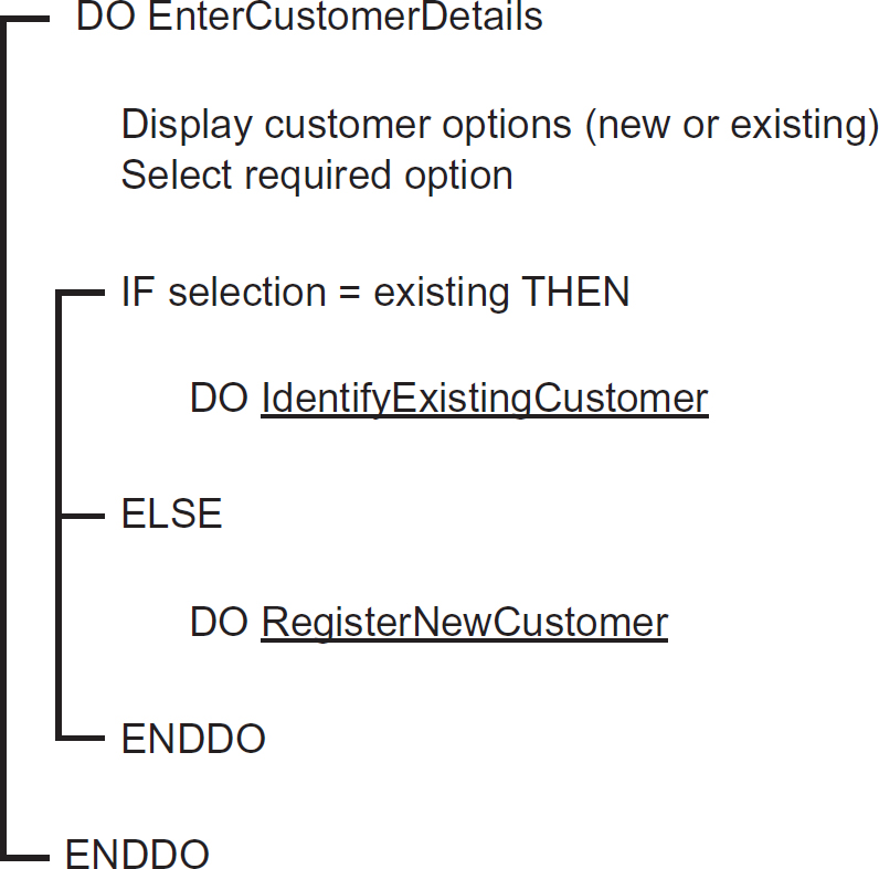
Figure 8.15 shows the same module specified using Structured English/pseudocode. Some of the words are in upper case, which denotes the key elements of structure. The DO and ENDDO at the beginning and end of the code denote the start and end of a sequence construct. The IF, ELSE and ENDIF define the key elements of a selection construct. The use of lines ties together key elements of the same construct. The underlining indicates that the items underlined refer to names of other modules that are defined using separate pseudocode.
Object-oriented design
Object-oriented development (OOD) was introduced briefly in Chapter 6 as a programming paradigm (theoretical framework) based around the concept of an object. Objects are defined by their properties or characteristics (attributes) and their behaviour (the services that they provide to other objects). In object-oriented (OO) systems, the system requirements are realised by the interaction of objects, whereby an object invokes a service from another object in order to provide its own services and realise the required functionality of the system.
In software terms, an object is a discrete package of data and processes (operations), that typically relates to a particular real-world thing (such as a product), a conceptual idea (such as a skill that a person possesses) or an event that has (or will) taken place (such as a training course).
Figure 8.15 Pseudocode specification of the Enter Customer Details module
Sticking with our theme of a sales order processing system, Figure 8.16 shows the definition of an order object, using UML class diagram notation. In OO theory, a class is a template for a kind of object.
Figure 8.16 Definition of an order object
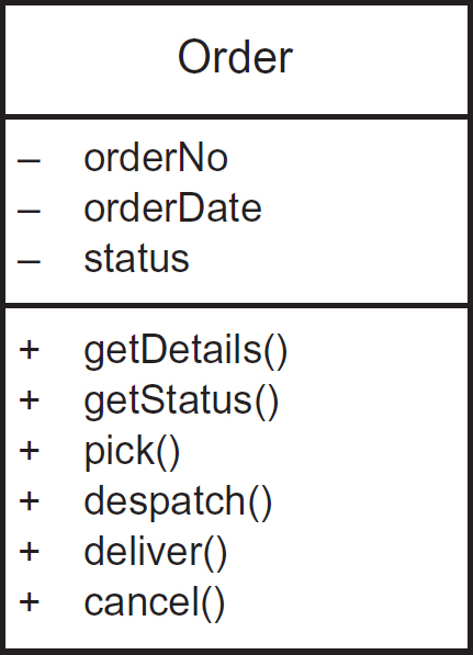
In this simple class definition there are three attributes (in practice there are likely to be more) and six operations (again, in practice there may be more). The attributes are prefixed with a minus sign and the operations a plus sign. This highlights a fundamental concept within OO design: encapsulation. This means that the inner workings of an object are invisible to outsiders, in other words, other objects. In UML the plus symbol (meaning public) and minus symbol (meaning private) are referred to as adornments and indicate the visibility of the elements that they prefix. Hence, the attributes of the object are said to be private (not visible to other objects) whilst the operations are public (visible to other objects).
An object can only access another object by sending a message to it. The message invokes the operation in the receiving object with the same name as the message. Consequently, when specifying OO processes, the designer produces some form of interaction diagram showing the explicit messages being sent between objects in order to realise the required functionality defined in a use case. Isolating objects in this way makes software easier to manage, more robust and reusable.
Other key concepts within OO design are abstraction, generalisation and polymorphism. These are all demonstrated within Figure 8.17, which shows a partial class model for an insurance policy administration system.
Figure 8.17 Class model showing abstraction (generalisation) and polymorphism

Abstraction captures only those details about an object that are relevant to the current perspective, as with abstract art, which hides irrelevant details. For example, when considering the vehicle insured by a Motor policy, as in Figure 8.17, although the vehicle has a colour, number of doors, engine capacity and gearbox type, none of these details is relevant to the policy administration system, and hence, they are not included in the class diagram.
Generalisation is a form of abstraction, whereby the common elements of a number of different types of ‘thing’ (such as a policy, as shown above) are grouped together into a super-class (called the generalisation) and the elements that are specific to each subtype are shown as sub-classes (called specialisations). Hence, in Figure 8.17, Policy is the generalisation and Household, Motor and Life are the specialisations.
In OO design, sub-classes inherit characteristics (attributes, operations and associations) from their parent super-class. Hence, Household, Motor and Life, as well as having their own specific attributes, also inherit policyNo, startDate and renewalDate from the Policy class. The attributes of the Policy class are shown with the hash visibility adornment (#). This denotes that the attributes of the generalised class are visible to the sub-classes as well.
Similarly, the sub-classes also inherit the operations getDetails(), checkStatus(), makeClaim(), renew() and cancel() from the Policy class. Furthermore, although not immediately obvious from the class diagram, they also have an association with the PolicyHolder class, although the Life class also has its own association with Medical, which is not shared with any of the other types of policy.
Polymorphism (meaning literally ‘many forms’) is a technique used by OO designers and programmers to override the functionality defined at the super-class level within specific sub-classes. So in Figure 8.17 we can see that the operation renew() defined within the Policy super-class is overridden with a different implementation for the sub-class Life. This reflects the fact that the renewal process for life policies differs from all other policies, perhaps as a consequence of requiring a new medical each time.
REFERENCES AND FURTHER READING
For References and Further Reading, please see the end of Chapter 9.